LG LC370WXN-SAB1-621液晶屏维修手册(电路原理图)
 "LG LC370WXN-SAB1-621液晶屏维修手册(电路原理图)-0")
 "LG LC370WXN-SAB1-621液晶屏维修手册(电路原理图)-1")
 "LG LC370WXN-SAB1-621液晶屏维修手册(电路原理图)-2")
 "LG LC370WXN-SAB1-621液晶屏维修手册(电路原理图)-3")
 "LG LC370WXN-SAB1-621液晶屏维修手册(电路原理图)-4")
 "LG LC370WXN-SAB1-621液晶屏维修手册(电路原理图)-5")
 "LG LC370WXN-SAB1-621液晶屏维修手册(电路原理图)-6")
 "LG LC370WXN-SAB1-621液晶屏维修手册(电路原理图)-7")
 "LG LC370WXN-SAB1-621液晶屏维修手册(电路原理图)-8")
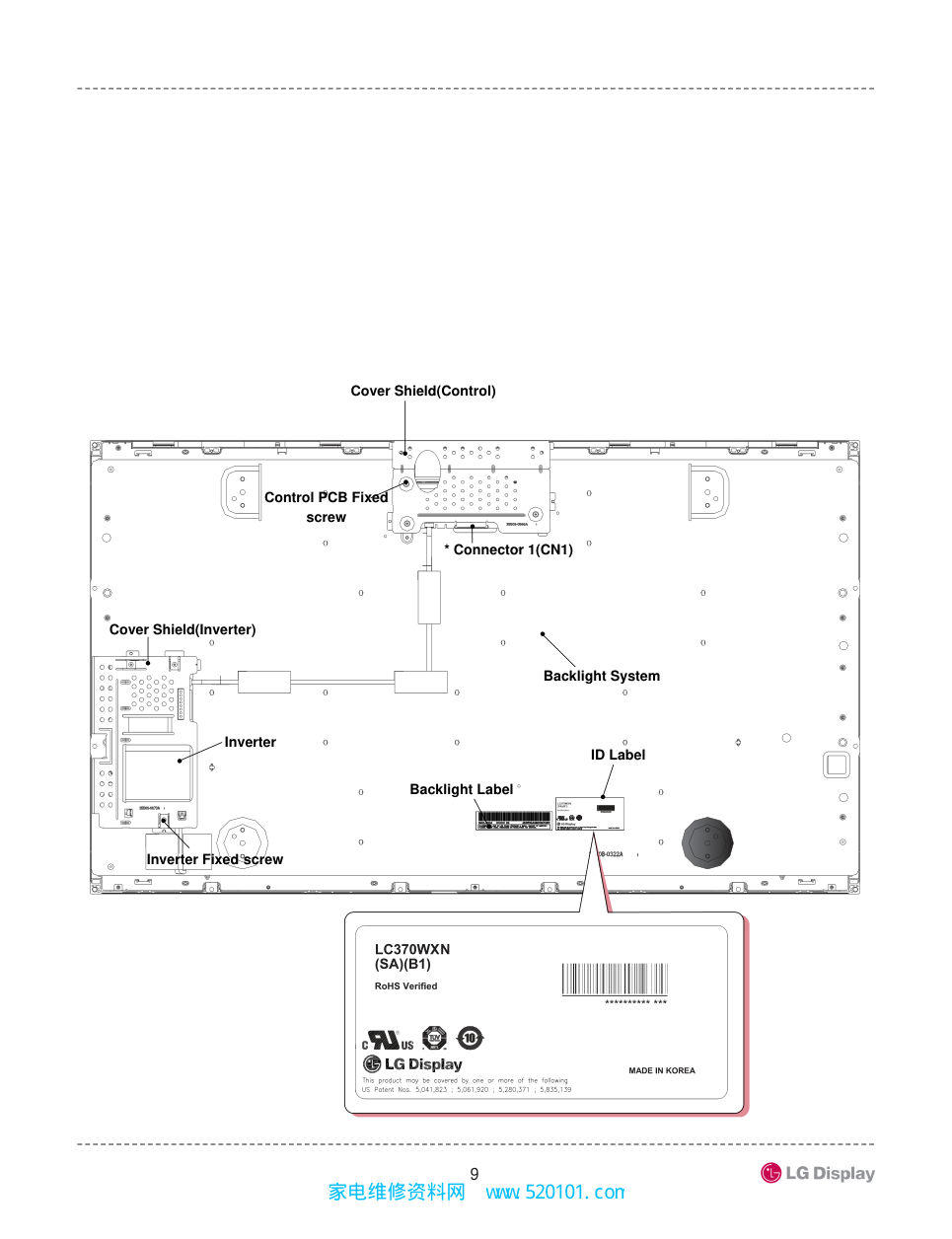
 "LG LC370WXN-SAB1-621液晶屏维修手册(电路原理图)-9")
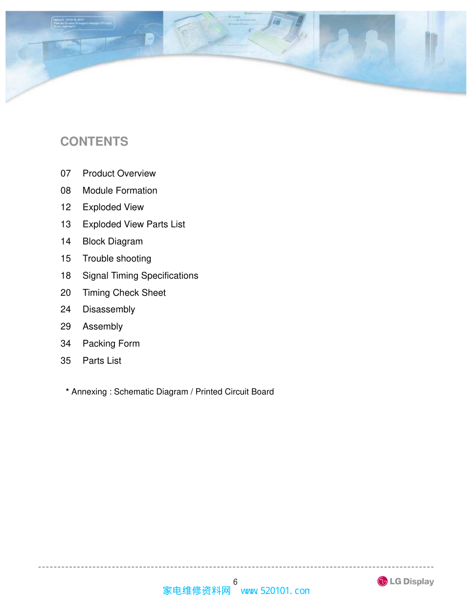
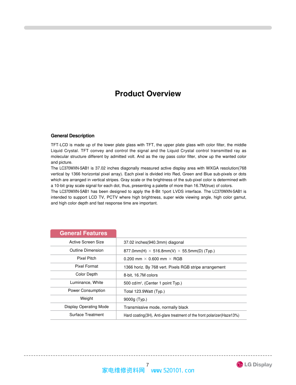
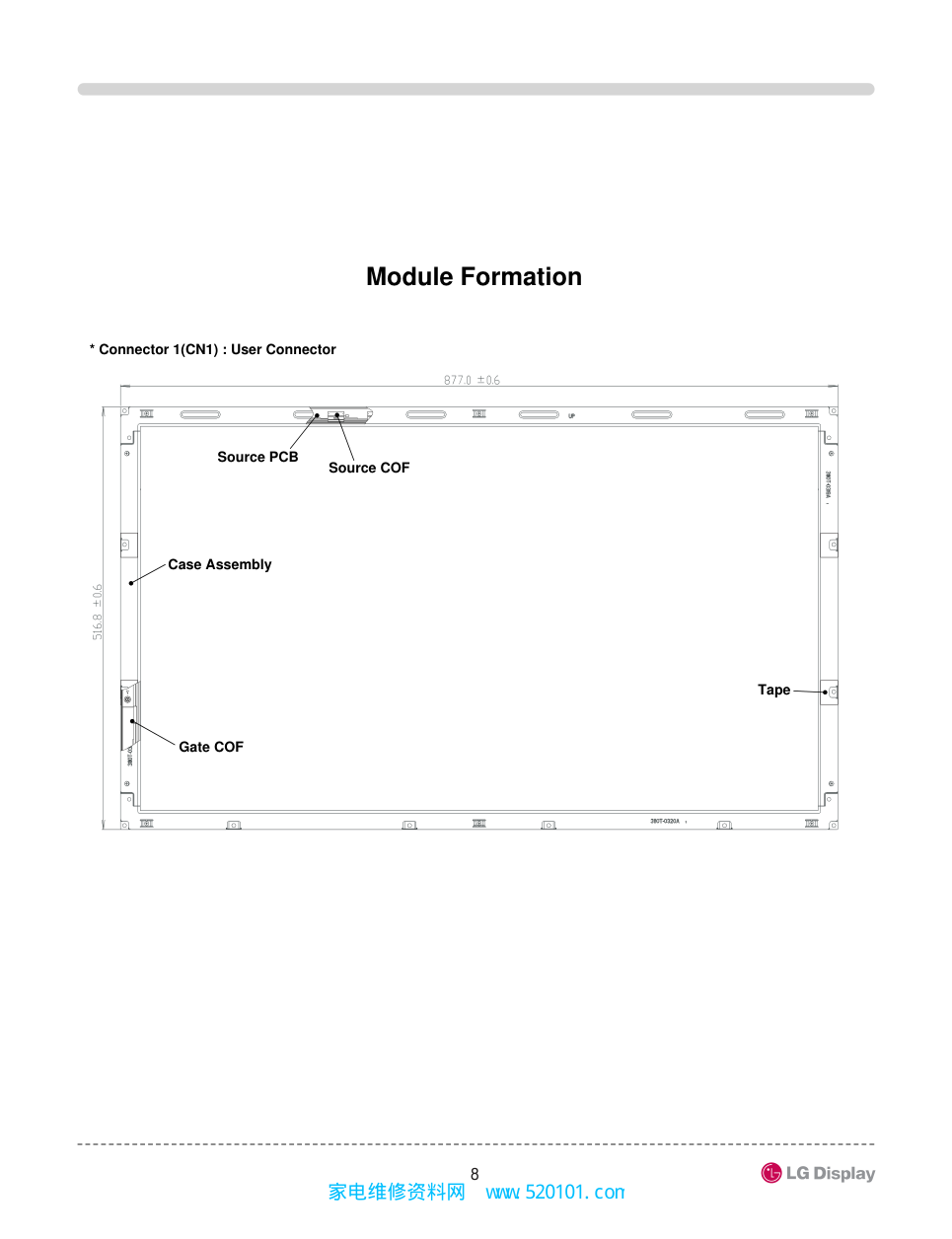
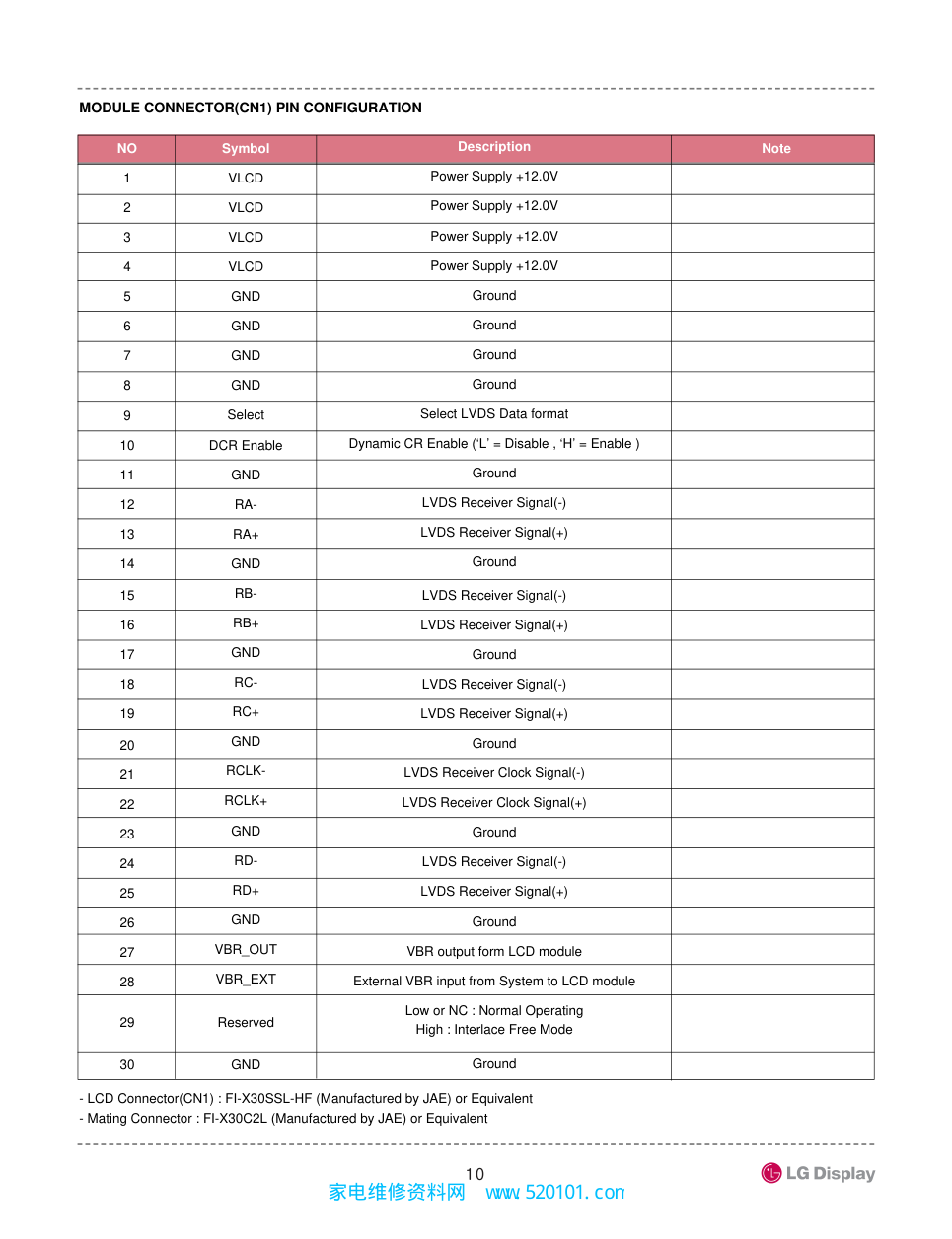
LC370WXN-SAB1-621 [ RoHS Verified ] 家电维修资料网 www. 520101. com � Warning? Warning statements identify conditions or practices that could result in injury or loss of life if the warning is ignored and the product is handled incorrectly. Caution? Caution statements identify conditions or practices that could result in damage to this product or other property if the caution is ignored and the product is handled incorrectly. �� WARNING (1) Do not supply a voltage higher than that specified to this product. This may damage the product and may cause a fire. (2) Do not use this product in locations where the humidity is extremely high, where it may be splashed with water, or where flammable materials surround it. (3) Do not install or use the product in a location that dose not satisfy the specified environmental conditions. This may damage the product and may cause a fire. (4) If a foreign substance (such as water, metal, or liquid)gets inside the product, immediately turn off the power. Continuing to use the product and cause fire or electric shock. (5) If the product emits smoke or abnormal noise, immediately turn off the power. Continuing to use the product cause fire or electric shock. (6) Do not disconnect or connect the connector while the power is on. (7) Do not pull out or insert the power cable from/to an outlet with wet hands. It may cause electric shock. (8) If the power cable is damaged or the connector is loose, do not use the product : otherwise this can lead to fire or electric shock. (9) Backlight Inverter uses a high voltage for Lamp. Do not touch circuit substrate and caution on electric shock when handling the LCD Module Backlight Inverter unit. SAFETY PRECAUTIONS Review the following safety precautions to avoid injury and prevent damage to this product or any products connected to it. To avoid potential hazards, use this product only as specified. Only qualified personnel should perform service procedures. LCD Module is a display device to be divided into Board Assembly and Backlight Assembly. Board Assembly consists of electric circuitry, PCB and two sheets of glass. Polarizer films are attached on each surface. The space between two sheets of glass are filled with Liquid Crystal. And the Backlight Assembly includes Lamp Assembly, optical sheets(Diffuser, Prism), optical plate, supporter main. When using / handing this LCD Module, pay attention to the below warning and cautions. 家电维修资料网 www. 520101. com � �� CAUTION (1) Do not place this product in a location that is subject to heavy vibration, or an unstable surface such as an inclined surface. The product may fall off or fall over, causing injuries. (2) Before disconnecting cable from the product, be sure to turn off the power. Be sure to hold the connector when disconnecting cables. Pulling a cable with excessive force may cause the core of the cable to be exposed or break the cable, and this can lead to fire or electric shock. (3) This product contains glass. If shock, vibration, heat or distortion is applied to the product, the glass may be broken. (4) If glass surface of the display breaks or is scratched, do not touched the broken pieces or the scratched with bare hands. You may be injured. (5) LCD Module requires to be handled with special care. LCD Module is not to be touched with metal or hard materials. Must not be stressed by heat or mechanical impact. (6) There are some particular components on the rear panel of this product. Skin contact with these components may cause an electric shock. So, handle with care. (7) While moving the product, be sure to turn off the power, disconnect all cables and watch your step. Dropping the product may cause injuries from electric shock. So, while moving the product handle with care. (8) When cleaning the panel is necessary, wipe it with a soft and moistened cloth a neural detergent. Caution on connector area. Do not use chemicals such as thinner or benzene. (9) LCD Module emits heat from the Lamp, Backlight lamp, component parts. Therefore, the environmental temperature must not exceed 50�. LCD Module Backlight Inverter system is driven by high voltage, so it must avoid conductive materials. (10) If repairing components with a lead line, high voltage or high temperature components must be put out from a lead line and fix. (11) Do not place an object on the surface of the display. The glass may break or be scratched. (12) This product may be damaged if it is subject to excessive stresses (such as excessive voltage, current, or temperature). The absolute maximum ratings specify the limits of these stresses. (13) Do not cover or wrap with any covering materials while power is applied to the product. (14) This product is made from various material such as glass, metal, and plastic. When discarding it, be sure to contact a purchase place. (15) If a discrepancy occurs due to any arbitrary modification or disassembly, LG Display is not responsible for function, quality or other items. (16) Within the warranty period, general faults may be charged for depending on responsibility for the faults. You handle with care. 家电维修资料网 www. 520101. com � SERVICING PRECAUTIONS ����System Assembler (1) Follow power sequence. �Abnormal power sequence may cause critical malfunction or electrical damage. (2) Prevent physical stress. (3) Prevent overheat. �High temperature on the surface of the screen may cause poor quality. Please make LCD Module used on specified temperature. �Low temperature under 10�makes LCD Module respond slowly, make Backlight worse operated and shorten very much the lifetime accordingly. (4) Keep LCD Module dust-free. �LCD Module is sensitive against dust. Dust can cause visual or functional problem. (5) Do not touch TCP area. �Do not touch TCP area at any case. It causes Driver IC crack, film crack etc. TCP is the weakest point of LCD Module. (6) Do not pull Backlight wire. �Please do not pull the Backlight wire it can cause the wire disconnected or damaged. (7) Check a connection of the Inverter & Backlight connectors. �Incomplete connection with can cause burnt in Backlight connector or damage the inverter. (8) Handle with care. �Please do not drop, bend or hit the LCD Module. Physical stress can cause the defect such as broken. (9) Keep mounting screw length and motor driver’s torque. �Strong weaken motor driver’s torque can make a mechanical defect on LCD Module. Please keep the specification. (10) Do not operate for a long time under the same pattern. �Operating LCD Module for a long time under the same pattern can cause image persistence and can damage it. (11) Defect panel also handled with care. �To prevent making another defect, please handle the defective LCD Module as a good one. �Defective LCD Module should be repaired. (12) Do not stack LCD Modules. �LCD Module consists of fragile components such as TCPs or Glasses. �Stacking LCD Module can cause undesired defects. Color TFT LCD Module is apt to be damaged by both electrical and mechanical stresses. Users, therefore, are requested to follow the “Servicing precautions of color TFT LCD Module” on the followings. CAUTION “Before servicing the module, read the safety precautions in this manual.” 家电维修资料网 www. 520101. com � (13) Do not provide strong pressure at connecting. �Strong pressure can transfer the force to TCP which is the weakest parts of LCD Module. Eventually can make TCP crack or other unexpected defect. (14) Let the Backlight Wire backside of LCD Module. �If let the Backlight wire front side of LCD Module, the Backlight connector can hurt the surface of polarizer. (15) Never connect/disconnect at power on. �LCD Module consists of CMOS which is known as weak component against EOS. It can hurt the product. (16) Electro-static discharge can make damage. �Semi-assembled product should be handled with wrist strap. �Earth human body when handle the LCD Module. Please do not touch the interface connector pin. ����System Assembler/End User (1) Keep clean the surface. �Please wear rubber glove when touch the surface of LCD Module screen. �Please use soft and anti-static material with n-Hexane as cleaner. (2) Be careful not to make polarizer scratch. �Surface of polarizer is soft, so it’s easily scratched. �Please do not touch, press or rub on polarizer surface with materials over HB hardness. (3) Be careful swift Temperature & Humidity change. �Swift temperature and or humidity change can make dew condensation or ice which cause nonconformance such as malfunction. (4) Keep out of water. �Water on in the LCD Module can cause electrical short or corrosion. �Please wipe out or dry water carefully. (5) Keep LCD Module corrosive gases free. �Corrosive gas makes the polarizer and the circuitry parts chemical damages and eventually cause defects. (6) Keep the suitable temp. & suitable humidity. �High temp. & high humidity shorten the lifetime. 家电维修资料网 www. 520101. com � 07 Product Overview 08 Module Formation 12 Exploded View 13 Exploded View Parts List 14 Block Diagram 15 Trouble shooting 18 Signal Timing Specifications 20 Timing Check Sheet 24 Disassembly 29 Assembly 34 Packing Form 35 Parts List * Annexing : Schematic Diagram / Printed Circuit Board CONTENTS 家电维修资料网 www. 520101. com � General Features 37.02 inches(940.3mm) diagonal 877.0mm(H) � 516.8mm(V) � 55.5mm(D) (Typ.) 0.200 mm � 0.600 mm � RGB 1366 horiz. By 768 vert. Pixels RGB stripe arrangement 8-bit, 16.7M colors 500 cd/m2, (Center 1 point Typ.) Total 123.9Watt (Typ.) 9000g (Typ.) Transmissive mode, normally black Hard coating(3H), Anti-glare treatment of the front polarizer(Haze13%) General Description TFT-LCD is made up of the lower plate glass with TFT, the upper plate glass with color filter, the middle Liquid Crystal. TFT convey and control the signal and the Liquid Crystal control transmitted ray as molecular structure different by admitted volt. And as the ray pass color filter, show up the wanted color and picture. The LC370WXN-SAB1 is 37.02 inches diagonally measured active display area with WXGA resolution(768 vertical by 1366 horizontal pixel array). Each pixel is divided into Red, Green and Blue sub-pixels or dots which are arranged in vertical stripes. Gray scale or the brightness of the sub-pixel color is determined with a 10-bit gray scale signal for each dot, thus, presenting a palette of more than 16.7M(true) of colors. The LC370WXN-SAB1 has been designed to apply the 8-Bit 1port LVDS interface. The LC370WXN-SAB1 is intended to support LCD TV, PCTV where high brightness, super wide viewing angle, high color gamut, and high color depth and fast response time are important. Active Screen Size Outline Dimension Pixel Pitch Pixel Format Color Depth Luminance, White Power Consumption Weight Display Operating Mode Surface Treatment Product Overview 家电维修资料网 www. 520101. com � Module Formation Case Assembly Source PCB Source COF * Connector 1(CN1) : User Connector Gate COF Tape 家电维修资料网 www. 520101. com � ��� ��� RoHS Verified LC370WXN (SA)(B1) * Connector 1(CN1) Cover Shield(Control) Backlight System ID Label Backlight Label Cover Shield(Inverter) Inverter Control PCB Fixed screw Inverter Fixed screw 家电维修资料网 www. 520101. com �� MODULE CONNECTOR(CN1) PIN CONFIGURATION NO 1 2 3 4 5 6 7 8 9 10 11 12 13 14 15 16 17 18 19 20 21 22 23 24 25 26 27 28 29 30 Symbol VLCD VLCD VLCD VLCD GND GND GND GND Select DCR Enable GND RA- RA+ GND RB- RB+ GND RC- RC+ GND RCLK- RCLK+ GND RD- RD+ GND VBR_OUT VBR_EXT Reserved GND Note VLCD VLCD VLCD VLCD GND GND GND GND Note 1 NC GND RA- RA+ GND RB- RB+ GND RC- RC+ GND RCLK- RCLK+ GND RD- RD+ GND NC NC GND GND Description Power Supply +12.0V Power Supply +12.0V Power Supply +12.0V Power Supply +12.0V Ground Ground Ground Ground Select LVDS Data format Dynamic CR Enable (‘L’ = Disable , ‘H’ = Enable ) Ground LVDS Receiver Signal(-) LVDS Receiver Signal(+) Ground LVDS Receiver Signal(-) LVDS Receiver Signal(+) Ground LVDS Receiver Signal(-) LVDS Receiver Signal(+) Ground LVDS Receiver Clock Signal(-) LVDS Receiver Clock Signal(+) Ground LVDS Receiver Signal(-) LVDS Receiver Signal(+) Ground VBR output form LCD module External VBR input from System to LCD module Low or NC : Normal Operating High : Interlace Free Mode Ground - LCD Connector(CN1) : FI-X30SSL-HF (Manufactured by JAE) or Equivalent - Mating Connector : FI-X30C2L (Manufactured by JAE) or Equivalent 家电维修资料网 www. 520101. com �� INVERTER Connector Pin configuration NO 1 2 3 4 5 6 7 8 9 10 11 12 13 14 Symbol VBL VBL VBL VBL VBL GND GND GND GND GND VBR-A VON/OFF VBR-B Status Description Power Supply +24.0V Power Supply +24.0V Power Supply +24.0V Power Supply +24.0V Power Supply +24.0V Backlight Ground Backlight Ground Backlight Ground Backlight Ground Backlight Ground Analog dimming voltage DC 0.0V ~ 3.3V (Typ : 1.65V) 0.0V ~ 5.0V Burst dimming Voltage DC 0.0V ~ 3.3V Normal : Upper 3.0V Abnormal : Under 0.7V ���� VBL VBL VBL VBL VBL GND GND GND GND GND VBR-A On/Off VBR-B Status ���� Inverter Connector : S14B-PH-SMC (manufactured by YeonHo) or Equivalent - Mating Connector : PHR-14 or Equivalent 1. Connector 1) Connector(Receptacle) : S14B-PH-SMC-TB ( JST or Yeon Ho) 2) Mating Connector(Plug) : PHR14 (JST) * JST : Japan solderless Terminal Co.,Ltd. 家电维修资料网 www. 520101. com �� 12 10 11 01 02 05 08 07 15 17 06 09 19 04 13 16 18 03 14 Exploded View 家电维修资料网 www. 520101. com �� Exploded View Parts List No. PART NO. DESCRIPTION 01 5135L-0022F/0053J/0013K PROTECT FILM 02 7250L-0082C OPP Film Tape 03 3111L-0236A Case Top Assembly 04 4000L-0006A SCREW 05 6308L-1084A/1618A/1231A POLARIZER(TOP) 6308L-1085A/1619A/1232A POLARIZER(BOTTOM) 06 0IOKL-0114A COF(D-IC, Gate) 07 6871L-1353A PWB(PCB) Assembly, Source _ Left 08 6871L-1354A PWB(PCB) Assembly, Source _ Right 09 0ILUL-0049A COF(D-IC, Source) 10 6871L-1385A PWB(PCB) Assembly, Control 11 3550S-0566A Metal Cover Shield,Control 12 4000L-0006B SCREW 13 6851L-0090A FFC 14 6900L-0229G Backlight System 15 6091L-0716F Backlight Assembly 16 3550S-0587A Metal Cover Shield,INV. 17 6632L-0504A INVERTER 18 4000L-0038A SCREW 19 3880L-0016K BAG 家电维修资料网 www. 520101. com �� Block Diagram 家电维修资料网 www. 520101. com �� � No Display Means that the screen is not affected by the signal data when you connect the product to Backlight or user connector and then 12V input power ON/OFF. Trouble shooting Less than Electricity Consumption 150mA More than Electricity Consumption 150mA Input Current OK User Connector (C-PCB CN1) Cold soldering/Open/Short Check User Connector(CN1) Resoldering / Replace / Reassembly NG OK OK OK OK OK OK FFC(CN4,6) Assembly / Open Check FFC(CN4,6) Reassembly / Replace NG VCC Generation Block Cold soldering/Open/ Short Check R99, 89~93,C78~82 L1,D12 Under the Parts Resoldering / Replace NG VGH_S Generation Block Cold soldering/Open/ Short Check R81,84,86~88,C73~75,D15 Under the Parts Resoldering / Replace NG VGH Modulation Block Cold soldering/Open/ Short Check R76, C101, C102 Under the Parts Resoldering / Replace NG VDD Generation Block Cold soldering/Open/ Short Check R51,53,56,57, C57,58,C50~54,56,59 D11,L2 Under the Parts Resoldering / Replace NG TCON Block(UL1) Output Data Check UL1/Under the Parts Resoldering / Replace NG Power Block - Out Voltage -After of Open the U9 Output Check VCC(+3.3V) VGL(-5.0V),VDD(+16.5V) VGH(+24.0V) U9/Under the Parts Resoldering / Replace NG OK Fuse(F1) Open Check Fuse(F1) Replace NG C18,19,67,68,69,70 Short Check C18,19,67,68,69,70 Resoldering / Replace NG 家电维修资料网 www. 520101. com �� � Abnormal Display Means that the screen is affected by the signal data when you connect the product to Backlight or user connector and then turn 12V input power ON/OFF. User Connector (C-PCB CN1)Cold soldering/ Open/Short Check User Connector(CN1) Resoldering / Replace NG OK LVDS Termination Resistor Open/Short Check Under the Parts Resoldering / Replace NG OK S-PCB CN5,6 C-PCB CN4,6 Cold soldering/ Open/Short Check CN5,6 CN4,6 Resoldering / Replace NG Source PCB Gamma Block Gamma Voltage Level Check (VDD,G0~17,VCC) Open/Short/Value Check Under the Parts Resoldering / Replace NG OK FFC Assembly/Open/Short Check FFC Resoldering / Replace NG OK US1 Power Block Output Voltage/Open/Short Check US1/ Under the Parts Resoldering / Replace NG OK OK Vcom Compensation Block Cold soldering/Open/ Short Check Under the Parts Resoldering / Replace NG OK ASIC(UL1) Cold soldering/Open/Short/ Quality Check ASIC(UL1) Resoldering / Replace NG � Flicker Controling P-vcom, Check the change of screen P-vcom Readjust OK NG P-Vcom Block Cold soldering/Open/Short Check -R56,67,70,73,77~79, 82,C61,71,72,U5 Under the Parts Resoldering / Replace NG 家电维修资料网 www. 520101. com �� � Abnormal Color Means that the abnormal screen displays at specified color when you connect the product to Backlight or user connector and then turn 12V input power ON/OFF. ASIC (UL1) Cold soldering/Open/Short/ Badness Check NO ASIC(UL1) Resoldering/ Replace YES ASIC (UL1) Cold soldering/Open/Short/ Badness Check NO ASIC(UL1) Resoldering/ Replace YES ASIC (UL1) Cold soldering/Open/Short/ Badness Check NO ASIC(UL1) Resoldering/ Replace USER CNT(CN1)Cold soldering/Open/Short/ Badness/Cable assembly Check NO USER CNT(CN1) Resoldering/ Reassembly USER CNT(CN1)Cold soldering/Open/Short/ Badness/Cable assembly Check NO USER CNT(CN1) Resoldering/ Reassembly USER CNT(CN1)Cold soldering/Open/Short/ Badness/Cable assembly Check NO USER CNT(CN1) Resoldering/ Reassembly YES YES YES YES FFC Assembly/Open/ Short Check NO FFC Reassembly/ Replace YES FFC Assembly/Open/ Short Check NO FFC Reassembly/ Replace YES FFC Assembly/Open/ Short Check NO FFC Reassembly/ Replace C-PCB CN4, 6 Cold soldering/Open/ Short Check NO C-PCB CN4, 6 Resoldering/ Replace C-PCB CN4, 6 Cold soldering/Open/ Short Check NO C-PCB CN4, 6 Resoldering/ Replace C-PCB CN4, 6 Cold soldering/Open/ Short Check NO C-PCB CN4, 6 Resoldering/ Replace YES YES YES YES S-PCB AR1,2,11,12 Cold soldering/Short/ Open Check NO S-PCB AR Resoldering/ Replace YES S-PCB AR1,2,11,12 Cold soldering/Short/ Open Check NO S-PCB AR Resoldering/ Replace YES S-PCB AR1,2,11,12 Cold soldering/Short/ Open Check NO S-PCB AR Resoldering/ Replace S-PCB CN5,6 Cold soldering/Open/ Short Check NO S-PCB CN5,6 Resoldering/ Replace S-PCB CN5,6 Pool soldering/Open/ Short Check NO S-PCB CN5,6 Resoldering/ Replace S-PCB CN5,6 Pool soldering/Open/ Short Check NO S-PCB CN5,6 Resoldering/ Replace YES G Wrong Color B Wrong Color R Wrong Color 家电维修资料网 www. 520101. com �� Signal Timing Specifications 家电维修资料网 www. 520101. com �� Signal Timing Waveforms 家电维修资料网 www. 520101. com �� Timing Check Sheet ���� ���� 家电维修资料网 www. 520101. com �� CLK High CLK Low 家电维修资料网 www. 520101. com �� DATA Set up time DATA Hold time 家电维修资料网 www. 520101. com �� POL Set up time POL Hold Time 家电维修资料网 www. 520101. com �� Disassembly � Separate the Cover Shield(Control). � Should be put on (electro static) wrist strap. � Should be cleared the bottom. � Light the Ion Blower. � Separate the Control PCB. At this time, Seperate the FFC from the Source PCB. � Seperate the FFC from the Control PCB & Inverter. � If you need to replace the Inverter, separate the Inverter. It�s unnecessary to repair the normal TCP / Polarizer. � Separate Cover Shield(Control) � Separate Control PCB / FFC Cable � Separate FFC Cable � Separate Cover Shield(Inverter) � Separate Connector � Attach dummy sheet on the upper Polarizer. � Remove dust on the upper Polarizer. � Separate the fixed screw of Case Assembly. � Separate Case Assembly � Separate Board Assembly from Backlight Assembly. � Remove dust on the lower Polarizer. � Attach dummy sheet on the lower Polarizer. � Attach the dummy sheet on Backlight Assembly. � Charge the Backlight Assembly in Bag. � Take charge of Board Assembly in tray. 家电维修资料网 www. 520101. com �� � Separate the Cover Shield (Inverter). � If you need to replace the Inverter, separate the Inverter. It�s unnecessary to repair the normal TCP / Polarizer. � Separate the Connector. � If you need to replace the Inverter, separate the Inverter. It�s unnecessary to repair the normal TCP / Polarizer. � Separate the fixed screw of Case Assembly� � Separate the Case Assembly. 家电维修资料网 www. 520101. com �� � Remove dust on the upper Polarizer. � Attach the dummy sheet on the upper Polarizer. � Separate the Board Assembly from Backlight Assembly. � Remove dust on the lower Polarizer. 家电维修资料网 www. 520101. com �� � Attach the dummy sheet on the lower Polarizer. � Take charge of the Board Assembly in tray. � Attach the dummy sheet on Backlight Assembly. BOTTOM � Take charge of the Backlight Assembly in Bag. 家电维修资料网 www. 520101. com �� VACUUM PAD Atmospheric pressure : 760 torr(1 pressure) It is used to move or assemble, disasemble the materials by making vacuum condition between Panel and Pad. also used on the condition of one or two level. when it is needed on the small inche�s LCM, use the 1 level vacuum pad. Vacuum PAD 家电维修资料网 www. 520101. com �� Assembly � Detach the protection film on the lower Polarizer. � Detach it to opposite direction for preventing static electricity. � Should be put on (electro static) wrist strap. � Should be cleared the bottom. � Light the Ion Blower. � Polish the lower Polarizer with soft wiper. � Remove dust of lower Polarizer with a Air Gun. � Detach the protection film on the lower Polarizer. � Clean the lower Polarizer. � Remove dust the lower Polarizer. � Detach the dummy sheet on Backlight Assembly. � Assemble Board Assembly with Backlight Assembly. � First screen inspection � Separate dummy sheet on the upper Polarizer. � Assemble the Case Assembly. � Assemble the fixed screw of Case Assembly. � Attach dummy sheet on the upper Polarizer. � Assemble the Cover Shield(Control) � Assemble the Cover Shield(Inverter) � Assemble the Connector � Separate dummy sheet on the upper Polarizer. � Attach the protection film on the upper Polarizer. � Final inspection � Wrap module � Clean the upper Polarizer. � Assemble Control PCB / FFC Cable 家电维修资料网 www. 520101. com �� � Detach the dummy sheet on Backlight Assembly. � Assemble the Board Assembly with Backlight Assembly. � Take a first screen inspection the Backlight. � Check the Backlight dust. � Separate the dummy sheet on the upper Polarizer. � Assemble the Case Assembly. 家电维修资料网 www. 520101. com �� � Assemble the fixed screw of Case Assembly. � Attach the dummy sheet on the upper Polarizer. � Assemble the Control PCB. At this time, Connect the FFC from the Source PCB. � Assemble the Connector. � Assemble the Cover Shield(Control) 家电维修资料网 www. 520101. com �� � Assemble the Cover Shield (Inverter). � Separate the dummy sheet on the upper Polarizer. � Detach it to opposite direction for preventing static electricity. � Polish the upper Polarizer with soft wiper. � Attach the protection film on the upper Polarizer. � Take a final inspection. 家电维修资料网 www. 520101. com �� BOTTOM BOTTOM � Wrap the module up in Shielding Bag. Caution 家电维修资料网 www. 520101. com �� 2 3 1 5 6 4 LC370WXN-SAB1 Packing Assembly LC370WXN-SAB1 Pallet Assembly 2 4 6 3 7 8 9 5 *Caution* 1 NO. Description Material P/N 1 LCM MODULE 2 BAG AL 3880L-0016K 3 PACKING, TOP(R) EPS 3920L-0890A 4 PACKING, TOP(L) EPS 3920L-0889A 5 TAPE MASKING 20MMX50M 6 PACKING, BOTTOM EPS 3920L-0891B 7 BOX PAPER_DW 3890L-0028Q 8 LABEL ART, 100X70 9 TAPE OPP 70MMX300M NO. Description Material 1 PACKING Assembly 2 BAND, CLIP CLIP 18MM 3 BAND PP 4 ANGLE, PACKING PAPER, DW 5 LABEL ART, 100X100 6 PALLET Plywood_1140X990X117.5 Packing Form 家电维修资料网 www. 520101. com �� PART No. DESCRIPTION SPECIFICATION LOCA. No. 6060L-1001A BOARD assembly LC370WXN-SAB1-F11 6871L-1353A PCB Assembly Source, Left, LC370WXN-SAA1-F11(LEFT) 6871L-1354A PCB Assembly Source, Right, LC370WXN-SAA1-F11(RIGHT) 6871L-1385A PCB Assembly Control, Single, LC370WXN-SAB1-F11 0CHZL-0015A Array 10uF, Z, 10V, Y5V, 1.0mm, 3216, R/TP C92,C93 0CHZL-0004A Array 10uF, Z, 35V, Y5V, 1.5mm, 3225, R/TP C75 0CH2102K562 CAPACITOR,CHIP[CERAMIC 1NF 50V K X 1608 R/TP C18 0CH2103K562 CAPACITOR,CHIP[CERAMIC 10NF 50V K X 1608 R/TP C65,C86 0CH2472K562 CAPACITOR,CHIP[CERAMIC 4.7NF 50V K X 1608 R/TP C102 0CH2223H562 CAPACITOR,CHIP[CERAMIC 22NF 25V K X 1608 R/TP C62 0CH2104H942 MLCC 0.1uF, Z, 25V, Y5V, 0.85mm, 1608, R/TP C2,C5,C8 0CH2105D942 MLCC 1uF, Z, 10V, Y5V, 0.85mm, 1608, R/TP C1,C12,C4,C7 0CH2A-0008A MLCC 4.7uF, K, 25V, X5R, 0.95mm, 3216, R/TP C11,C45 0CH2A-0015A MLCC 1uF, K, 25V, X5R, 0.9mm, 1608, R/TP C10,C3,C43,C44,C6,C9 0CH2104H942 MLCC 0.1uF, Z, 25V, Y5V, 0.85mm, 1608, R/TP C51,C54,C57 0CH2105D942 MLCC 1uF, Z, 10V, Y5V, 0.85mm, 1608, R/TP C50,C53,C56,C59 0CH2A-0008A MLCC 4.7uF, K, 25V, X5R, 0.95mm, 3216, R/TP C49,C62,C98 0CH2A-0015A MLCC 1uF, K, 25V, X5R, 0.9mm, 1608, R/TP C48,C52,C55,C58,C61 0CH2A-0004A MLCC 10uF, K, 10V, X5R, 1.8mm, 3216, R/TP C103,C79,C80,C81,C88 0CH2A-0003A MLCC 10uF, K, 25V, X5R, 2.2mm, 3225, R/TP C104,C105,C107,C52,C53,C54,C58,C59,C67,C68, C69,C70 0CH2104H942 MLCC 0.1uF, Z, 25V, Y5V, 0.85mm, 1608, R/TP C1,C10,C11,C12,C13,C19,C2,C20,C21,C22,C23, C3,C4,C5,C6,C61,C7,C78,C8,C9 0CH2222K562 MLCC 2.2nF, K, 50V, X7R, 0.85mm, 1608, R/TP C101 0CH2104K562 MLCC 0.1uF, K, 50V, X7R, 0.85mm, 1608, R/TP C56,C63,C82 0CH2105H946 MLCC 1uF, Z, 25V, Y5V, 0.95mm, 2012, R/TP C72 0CH2A-0008A MLCC 4.7uF, K, 25V, X5R, 0.95mm, 3216, R/TP C71 0CH2A-0015A MLCC 1uF, K, 25V, X5R, 0.9mm, 1608, R/TP C50,C57,C66,C73,C74,C77,C84,C85 0CH2A-0016A MLCC 0.22uF, K, 10V, X7R, 0.9mm, 1608, R/TP C91 0CH5331K412 Temp-compensation 330pF, J, 50V, C0G, 0.85mm, 1608, R/TP C51 0CH5680K412 Temp-compensation 68pF, J, 50V, C0G, 0.85mm, 1608, R/TP C64 0CH5391K412 Temp-compensation 390pF, J, 50V, C0G, 0.85mm, 1608, R/TP C83 0IETL-0011A Analog ISL43210IHZ-T, Intersil, 2.7 to 12, 28nsec, 20nsec, 5uW U6 0IROL-0005A EEPROM BR24L04FV-WE2, Rohm, 4K, 5msec, SSOP-B8, R/TP, 8 U8 0IRTL-0002D LDO RT9164A-18PG, RICHTEK, Fix_1.8V, 1A, SOT-223, R/TP, 4 US2 0ITIL-0063A Power TPS65162RGZR, TEXAS INSTRUMENT, TV_IPS US1 0IMXL-0007A P-VCom DS3501, MAXIM, 4.5 to 15.5, Resistor mode(10k), MSOP U5 0ITLL-0026A Timing TL2411MC, TLI, LVDS, 8, 1, Mini, 8, 1, DCR,ODC,SIP,KOMET UL1 6630L-0187A CONNECTOR GF05A-60S-AF, LS CABLE, 60 Pin, 0.5 mm, Angle, Au, NEW FPC CN5 Parts List (Specified parts list is subject to change.) CIRCUIT_CAPACITOR CIRCUIT_CONNECTOR CIRCUIT_IC 家电维修资料网 www. 520101. com �� PART No. DESCRIPTION SPECIFICATION LOCA. No. 6630L-0187A CONNECTOR GF05A-60S-AF, LS CABLE, 60 Pin, 0.5 mm, Angle, Au, NEW FPC CN6 6630L-0187A CONNECTOR GF05A-60S-AF, LS CABLE, 60 Pin, 0.5 mm, Angle, Au, NEW FPC CN4,CN6 6630L-0193A CONNECTOR GF10A-4S-LSS-AU, LS CABLE, 4 Pin, 1.0 mm, Angle, Sn, FPC CN2 6630L-0204A Wire-Board IS100-L30B-C23, UJU, 30PIN, 1.0MM, Angle, Female, R/TP, 2.3MM, Y CN1 0DHZL-0008A Schottky BAV99-7-F, DIODES, SOT-23, R/TP D15,D18 0DHZL-0029A Schottky B340A, DIODES, SMA, R/TP D11,D12 0IOKL-0114A Gate Drive IC MT3804VC01L, OKI, 256, N/A, N/A, C_B, R/TP, 35, 2, SPERFLEX 0ILUL-0049A Source Drive IC LS08S2M4-C2LS, Lusem, 690, 8, MINI, C_B, R/TP, 48, 5, SPERFLEX 6200C-0014A Bead BLM18EG601SN1D, MURATA, 0.35 Ohm, 1.6X0.8, R/TP R33,R51 6200C-0014A Bead BLM18EG601SN1D, MURATA, 0.35 Ohm, 1.6X0.8, R/TP R107,R114 6200L-J015A Bead BLM18PG300SN1D, MURATA, 30 ohm, 1.6X0.8X0.8 MM, R/TP FL4,FL6 6200C-0014A Bead BLM18EG601SN1D, MURATA, 0.35 Ohm, 1.6X0.8, R/TP FL2,R30,R32 0RH1201C422 chip 1.2K ohm, 1/16W, 1608, 1%, R/TP R14 0RH4701C422 chip 4.7K ohm, 1/16W, 1608, 1%, R/TP R22 0RH1002C422 chip 10K ohm, 1/16W, 1608, 1%, R/TP R23 0RH3302C422 chip 33K ohm, 1/16W, 1608, 1%, R/TP R12 0RH9101C422 chip 9.1K ohm, 1/16W, 1608, 1%, R/TP R25 0RH1000C422 chip 100 ohm, 1/16W, 1608, 1%, R/TP R10,R46,R47 0RH3900C422 chip 390 ohm, 1/16W, 1608, 1%, R/TP R24 0RH0000C622 chip 0 ohm, 1/16W, 1608, 5%, R/TP R53,R30,R54,R55,R56 0RH2401C422 chip 2.4K ohm, 1/16W, 1608, 1%, R/TP R20,R21 0RH2202C422 chip 22K ohm, 1/16W, 1608, 1%, R/TP R11 0RH1801C422 chip 1.8K ohm, 1/16W, 1608, 1%, R/TP R18 0RH7501C422 chip 7.5K ohm, 1/16W, 1608, 1%, R/TP R13 0RH3301C422 chip 3.3K ohm, 1/16W, 1608, 1%, R/TP R16,R17 0RHZL10005A chip 100 ohm, 1/16W, 3216, 5%, R/TP AR1,AR2 0RH1201C422 chip 1.2K ohm, 1/16W, 1608, 1%, R/TP R116 0RH2402C422 chip 24K ohm, 1/16W, 1608, 1%, R/TP R71 0RH8201C422 chip 8.2K ohm, 1/16W, 1608, 1%, R/TP R67 0RH6201C422 chip 6.2K ohm, 1/16W, 1608, 1%, R/TP R72 0RH1301C422 chip 1.3K ohm, 1/16W, 1608, 1%, R/TP R64 0RH5100C422 chip 510 ohm, 1/16W, 1608, 1%, R/TP R75 0RH1000C422 chip 100 ohm, 1/16W, 1608, 1%, R/TP R84,R85,R60 0RH2201C422 chip 2.2K ohm, 1/16W, 1608, 1%, R/TP R66 0RH2002C422 chip 20K ohm, 1/16W, 1608, 1%, R/TP R73 0RH0000C622 chip 0 ohm, 1/16W, 1608, 5%, R/TP R117,R118,R119,R120,R62,R98 0RH5101C422 chip 5.1K ohm, 1/16W, 1608, 1%, R/TP R70 0RH3602C422 chip 36K ohm, 1/16W, 1608, 1%, R/TP R74 0RH3301C422 chip 3.3K ohm, 1/16W, 1608, 1%, R/TP R68,R69 0RH6801C422 chip 6.8K ohm, 1/16W, 1608, 1%, R/TP R63 0RHZL10005A chip 100 ohm, 1/16W, 3216, 5%, R/TP AR11,AR12 0RH1201C422 chip 1.2K ohm, 1/16W, 1608, 1%, R/TP R29,R67,R73 0RH4701C422 chip 4.7K ohm, 1/16W, 1608, 1%, R/TP R23,R25,R27,R28 0RH9100C422 chip 910 ohm, 1/16W, 1608, 1%, R/TP R77 CIRCUIT_DIODE DRIVE_IC CIRCUIT_FILTER CIRCUIT_RESISTOR 家电维修资料网 www. 520101. com �� PART No. DESCRIPTION SPECIFICATION LOCA. No. 0RH3902C422 chip 39K ohm, 1/16W, 1608, 1%, R/TP R51 0RH0472C422 chip 47 ohm, 1/16W, 1608, 1%, R/TP R35,R37 0RH8201C422 chip 8.2K ohm, 1/16W, 1608, 1%, R/TP R53 0RH7502C422 chip 75K ohm, 1/16W, 1608, 1%, R/TP R86 0RH5601C422 chip 5.6K ohm, 1/16W, 1608, 1%, R/TP R65,R66,R71 0RH1500C422 chip 150 ohm, 1/16W, 1608, 1%, R/TP R15 0RH9101C422 chip 9.1K ohm, 1/16W, 1608, 1%, R/TP R82,R87 0RH8202C422 chip 82K ohm, 1/16W, 1608, 1%, R/TP R72 0RH6202C422 chip 62K ohm, 1/16W, 1608, 1%, R/TP R97 0RH1000C422 chip 100 ohm, 1/16W, 1608, 1%, R/TP R10,R114,R115,R116,R117,R98 0RH4301C422 chip 4.3K ohm, 1/16W, 1608, 1%, R/TP R78 0RH2002C422 chip 20K ohm, 1/16W, 1608, 1%, R/TP R20 0RH1004C422 chip 1M ohm, 1/16W, 1608, 1%, R/TP R8 0RH2703C422 chip 270K ohm, 1/16W, 1608, 1%, R/TP R95 0RH0000C622 chip 0 ohm, 1/16W, 1608, 5%, R/TP R19,R21,R38,R54,R58,R61,R69,R74,R76,R83,R9, R99 0RH5101C422 chip 5.1K ohm, 1/16W, 1608, 1%, R/TP R89 0RH3001C422 chip 3K ohm, 1/16W, 1608, 1%, R/TP R26,R55,R59 0RH4700C422 chip 470 ohm, 1/16W, 1608, 1%, R/TP R93 0RH1001C422 chip 1K ohm, 1/16W, 1608, 1%, R/TP R11,R12,R14,R50,R60,R79,R92,R94 0RH5603C422 chip 560K ohm, 1/16W, 1608, 1%, R/TP R64 0RH2401C422 chip 2.4K ohm, 1/16W, 1608, 1%, R/TP R75,R90 0RH2202C422 chip 22K ohm, 1/16W, 1608, 1%, R/TP R56 0RH3901C422 chip 3.9K ohm, 1/16W, 1608, 1%, R/TP R57 0RH1801C422 chip 1.8K ohm, 1/16W, 1608, 1%, R/TP R112,R33 0RH7501C422 chip 7.5K ohm, 1/16W, 1608, 1%, R/TP R88,R16 0RH2000C422 chip 200 ohm, 1/16W, 1608, 1%, R/TP R81 0RH3301C422 chip 3.3K ohm, 1/16W, 1608, 1%, R/TP R36 0RH6801C422 chip 6.8K ohm, 1/16W, 1608, 1%, R/TP R24,R70 0RH0682C422 chip 68 ohm, 1/16W, 1608, 1%, R/TP R121,R18,R113,R118,R119,R120 0RHAA-0002A chip 9.1K ohm, 1/4W, 3216, 5%, R/TP R84 0RH1002C422 chip 10K ohm, 1/16W, 1608, 1%, R/TP R13 0RH2201C422 chip 2.2K ohm, 1/16W, 1608, 1%, R/TP R49 0RH0202C422 chip 20 ohm, 1/16W, 1608, 1%, R/TP R17 6308L-1084A Polarizer NITTO, S, A, X, T, P, B, T, X, X, 8, 37, TOP *6308L-1618A Polarizer DONGWOO SMITOMO, S, A, X, T, P, S, T, X, X, L, 03700, TOP *6308L-1231A Polarizer LGC, S, A, X, S, P, B, S, X, X, 1, 37, TOP 6308L-1085A Polarizer NITTO, S, X, X, T, P, B, Z, X, I, 8, 37, BOTTOM *6308L-1619A Polarizer DONGWOO SMITOMO, S, X, X, T, P, S, Z, X, I, L, 03700, BOTTOM *6308L-1232A Polarizer LGC, S, X, X, S, P, B, A, X, I, 1, 37, BOTTOM 6632L-0504A Inverter KLS-EE37TKH16(A), KTY, LC370WXN-SAB1, ONE BOARD 6884L-0035A ANISOTROPIC CONDUCTIVE FILM CP5420ISL, SONY, L=2.0MMX300M, T=20 *6884L-0052A ANISOTROPIC CONDUCTIVE FILM CP2420ISL, SONY, L=2.0MMX300M, T=18 6884L-0044B ANISOTROPIC CONDUCTIVE FILM DP2252KSL(2.0MMX300M), SONY *6884L-0044C ANISOTROPIC CONDUCTIVE FILM AC-9825R-45(2.0MMX300M), HITACHI *6884L-0061A ANISOTROPIC CONDUCTIVE FILM CP20631-35YA, 2.0MMX300M, SONY CIRCUIT_POLARIZER INVERTER CIRCUIT_MISCELLANEOUS 家电维修资料网 www. 520101. com �� PART No. DESCRIPTION SPECIFICATION LOCA. No. 0TR900009BA Bipolar IMX9, ROHM, NP DUAL, TP, SMT6, N/A U2 0LCAA-0002A Coil CVOB8022-1R5220, COREVISION, 22UH, M=20%, 1.5A L1,L2 6851L-0129D FFC 6851L-0129D, EUNSUNG, 4pin, 466 mm, LC370WXN-SAA1, INVERTER *6851L-0129E FFC 6851L-0129E, STANDARD, 4pin, 466 mm, LC370WXN-SAA1, INVERTER 6851L-0090A FFC 6851L-0090A, STANDARD, 60pin, 54X30.5 mm, LC320WX3-SLC1, S-C 6640L-0002A FINGER SM-RUBBER, JSM-5-4-8,GASKET SMT TYPE, JOINSET SF2,SF4 6640L-0002A FINGER SM-RUBBER, JSM-5-4-8,GASKET SMT TYPE, JOINSET SF11,SF13 6212L-0002A Resonator 10MHz, +-30 PPM, 33pF, 3.2X1.3X0.7 mm, R/TP, -20~85'C RS1 0FS1501F032 Slow 43001.5 NRL, LITTELFUSE, Nickel, 63V, 1.5A, UL/CSA F1 家电维修资料网 www. 520101. com �� PART No. ITEM DESCRIPTION 3000L-0018V Angle Packing PAPER, DW, 1105X980X160 3890L-0028Q Box PAPER, DW, 952X350X570 3920L-0889A Packing TOP_L, EPS, LC370WUN 3920L-0890A Packing TOP_R, EPS, LC370WUN 3920L-0891B Packing BOTTOM, EPS, LC370WUN 3930L-0017A Pallet PLYWOOD, 1140X990X117.5 7250L-0041A TAPE(RAW) OPP 70MMX300M(LG,PHLIPS LCD) 3850L-0112A Label PALLET, ART, 100X100 3850L-0111A Label BOX, ART, 100X70 3850L-0088A Label ID, YUPO, 78X37 6900L-0229G Backlight System LC370WXN-SAB1-F21 6091L-0716F Backlight Assembly LC370WXN-SAB1-F21 3550S-0587A Metal Cover Shield INV, EGI, T0.5, LC370WXN-SAA1 6912L-0466A Lamp EEFL HEESUNG ELECTRONICS, 0.254/0.221, N/A, D3.4, L860, I Type 3880L-0016K Bag AL, 970X715(37) 3111L-0236A Case Top Assembly NORMAL, LC370WUN-SAA1-F11 3550S-0566A Metal Cover Shield CONTROL, EGI,T0.5, LC370WXN-SAA1 5135L-0022F Protect Film KOISE, KPF-100, N/A, N/A *5135L-0053J Protect Film KOISE, KOP-070A, 854X489, LC370W *5135L-0013K Protect Film SKC, HH10, 854X489X0.1, LC370WX1 4000L-0006A Screw SWCH18A, MACHINE, BIND HEAD, M2.6, L=12.0, NI 4000L-0006B Screw SWCH18A, MACHINE, BIND HEAD, M2.6, L=4.0, NI 4000L-0038A Screw SWCH18A, MACHINE, PAN HEAD, M3=0, L=5.0, NI 7250L-0319A Single Side Tape SOOKWANG, SINGLE, OPP, YELLOW, 20MMX50M 7250L-0082C TAPE(RAW) OPP FILM TAPE LABEL BACKLIGHT MECHANICAL PART PACKING & BOX 家电维修资料网 www. 520101. com [ AI I / F BLOCK] [ ASI C OPTI ON BLOCK] [ EEPROM BLOCK] [ MECH_ CI RCUI T GND BL OCK] [ CONTROL - SOURCE LEFT CONNECT OR] [ SPREAD SPECTRUM] [ USER CONNECT OR] [ WAVY I / F BL OCK- 4PI N] [ T_CON BLOCK ] [ ASI C CONTROL SI GNAL BL OCK] [ RESET BLOCK] [ CONT ROL- SOURCE RI GHT CONNECT OR] 家电维修资料网 www. 520101. com [ P- VCOM BLOCK] 家电维修资料网 www. 520101. com 家电维修资料网 www. 520101. com 家电维修资料网 www. 520101. com Printed Circuit Board ������� SOURCE(Left_Top) SOURCE(Right_Top) Control(Top) 家电维修资料网 www. 520101. com MODEL : LC370WXN-SAB1-621 September 2008 Printed in Korea 家电维修资料网 www. 520101. com
版权声明
1. 本站所有素材,仅限学习交流,仅展示部分内容,如需查看完整内容,请下载原文件。
2. 会员在本站下载的所有素材,只拥有使用权,著作权归原作者所有。
3. 所有素材,未经合法授权,请勿用于商业用途,会员不得以任何形式发布、传播、复制、转售该素材,否则一律封号处理。
4. 如果素材损害你的权益请联系客服QQ:77594475 处理。