索尼SONY HCD-DX9音响电路图
 "索尼SONY HCD-DX9音响电路图-0")
 "索尼SONY HCD-DX9音响电路图-1")
 "索尼SONY HCD-DX9音响电路图-2")
 "索尼SONY HCD-DX9音响电路图-3")
 "索尼SONY HCD-DX9音响电路图-4")
 "索尼SONY HCD-DX9音响电路图-5")
 "索尼SONY HCD-DX9音响电路图-6")
 "索尼SONY HCD-DX9音响电路图-7")
 "索尼SONY HCD-DX9音响电路图-8")
 "索尼SONY HCD-DX9音响电路图-9")
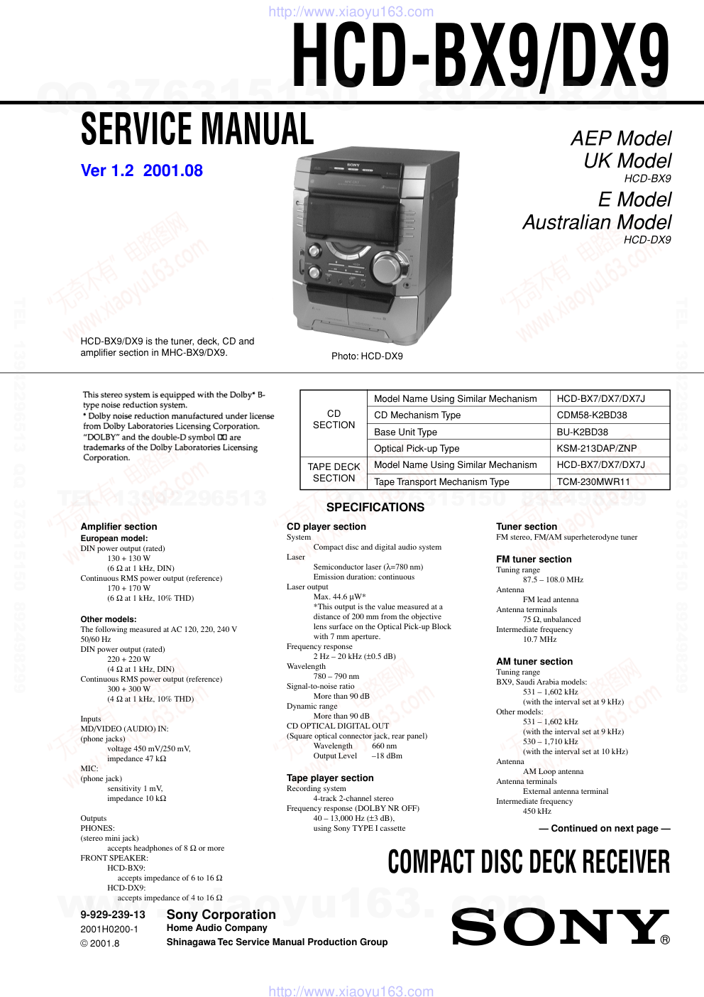
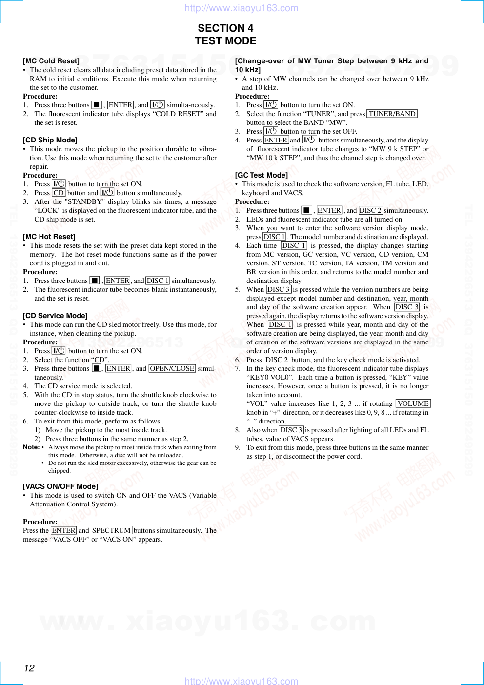
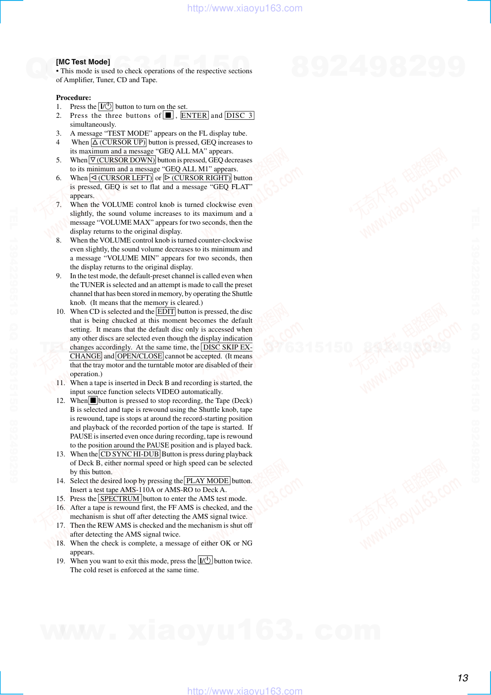
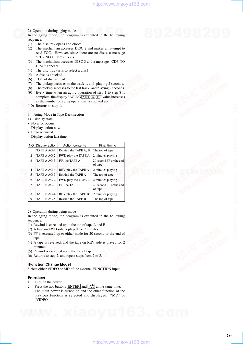
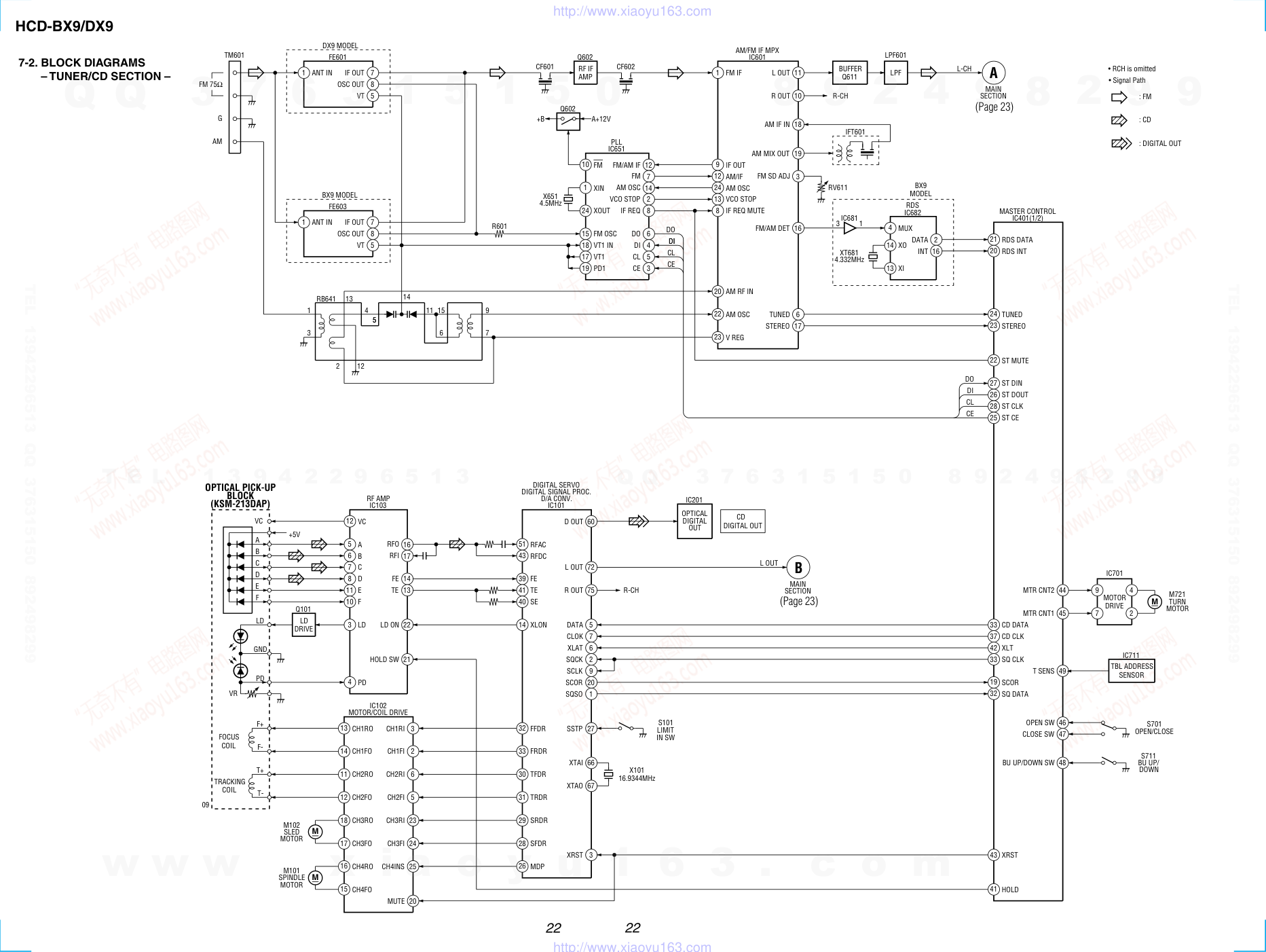
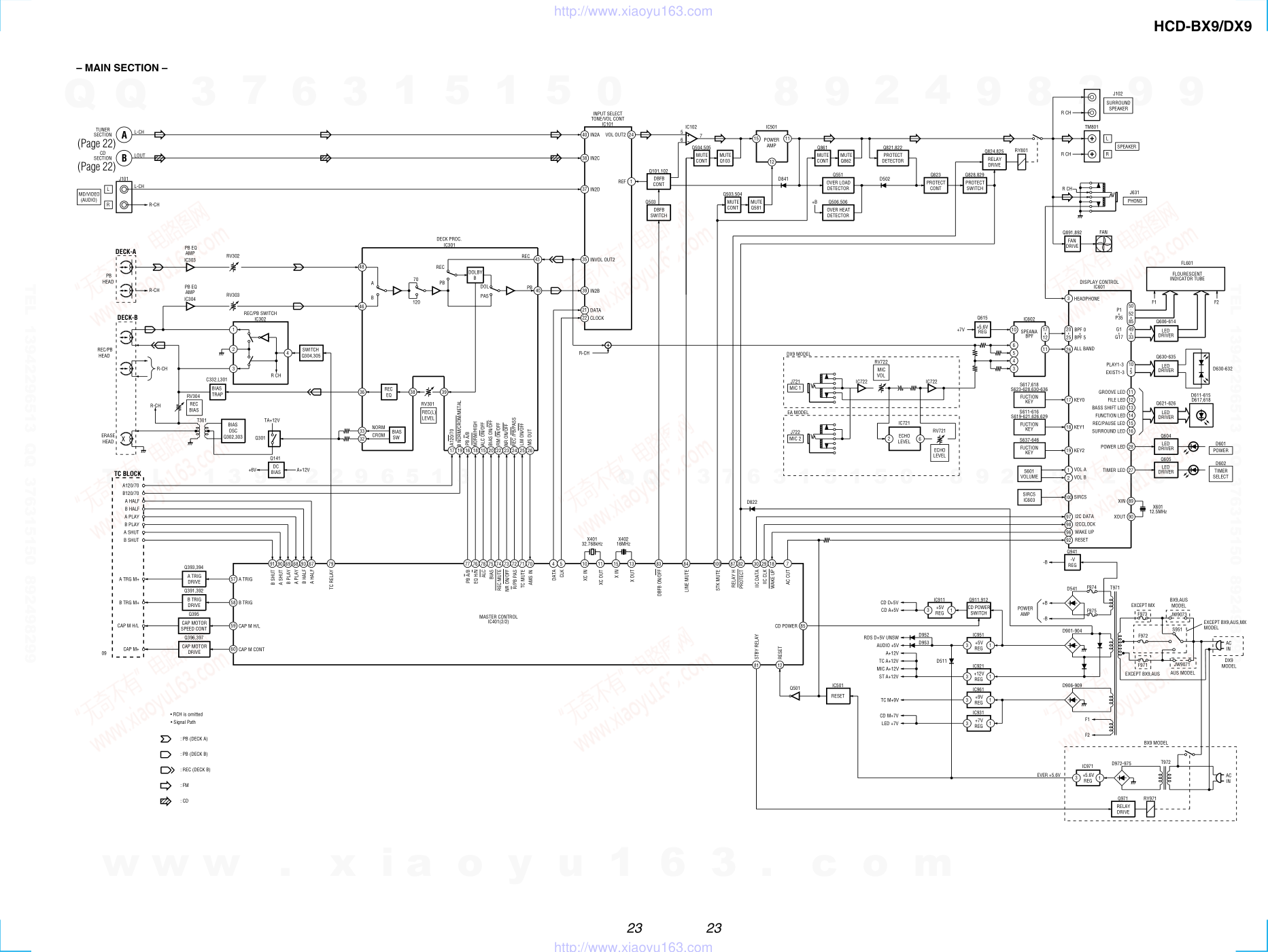
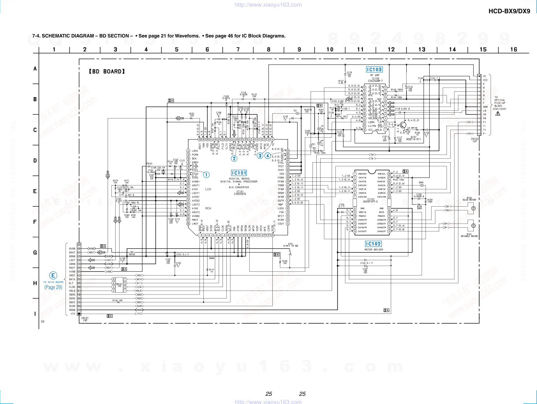
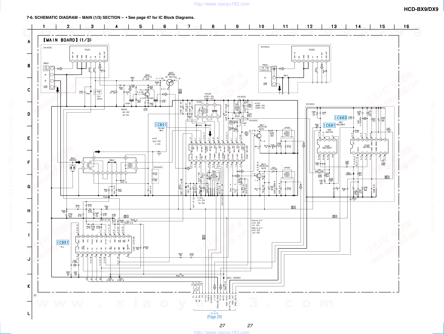
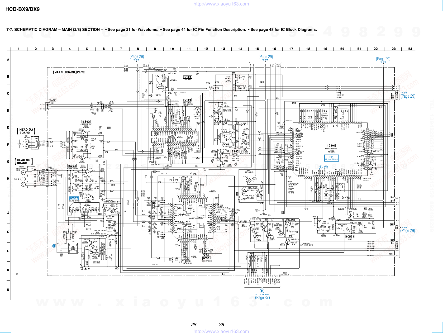
1 HCD-BX9/DX9 SERVICE MANUAL HCD-BX9/DX9 is the tuner, deck, CD and amplifier section in MHC-BX9/DX9. SPECIFICATIONS COMPACT DISC DECK RECEIVER — Continued on next page — Model Name Using Similar Mechanism HCD-BX7/DX7/DX7J CD Mechanism Type CDM58-K2BD38 Base Unit Type BU-K2BD38 Optical Pick-up Type KSM-213DAP/ZNP Model Name Using Similar Mechanism HCD-BX7/DX7/DX7J Tape Transport Mechanism Type TCM-230MWR11 CD SECTION TAPE DECK SECTION Photo: HCD-DX9 AEP Model UK Model HCD-BX9 E Model Australian Model HCD-DX9 Amplifier section European model: DIN power output (rated) 130 + 130 W (6 Ω at 1 kHz, DIN) Continuous RMS power output (reference) 170 + 170 W (6 Ω at 1 kHz, 10% THD) Other models: The following measured at AC 120, 220, 240 V 50/60 Hz DIN power output (rated) 220 + 220 W (4 Ω at 1 kHz, DIN) Continuous RMS power output (reference) 300 + 300 W (4 Ω at 1 kHz, 10% THD) Inputs MD/VIDEO (AUDIO) IN: (phone jacks) voltage 450 mV/250 mV, impedance 47 kΩ MIC: (phone jack) sensitivity 1 mV, impedance 10 kΩ Outputs PHONES: (stereo mini jack) accepts headphones of 8 Ω or more FRONT SPEAKER: HCD-BX9: accepts impedance of 6 to 16 Ω HCD-DX9: accepts impedance of 4 to 16 Ω CD player section System Compact disc and digital audio system Laser Semiconductor laser (λ=780 nm) Emission duration: continuous Laser output Max. 44.6 µW* *This output is the value measured at a distance of 200 mm from the objective lens surface on the Optical Pick-up Block with 7 mm aperture. Frequency response 2 Hz – 20 kHz (±0.5 dB) Wavelength 780 – 790 nm Signal-to-noise ratio More than 90 dB Dynamic range More than 90 dB CD OPTICAL DIGITAL OUT (Square optical connector jack, rear panel) Wavelength 660 nm Output Level –18 dBm Tape player section Recording system 4-track 2-channel stereo Frequency response (DOLBY NR OFF) 40 – 13,000 Hz (±3 dB), using Sony TYPE I cassette Tuner section FM stereo, FM/AM superheterodyne tuner FM tuner section Tuning range 87.5 – 108.0 MHz Antenna FM lead antenna Antenna terminals 75 Ω, unbalanced Intermediate frequency 10.7 MHz AM tuner section Tuning range BX9, Saudi Arabia models: 531 – 1,602 kHz (with the interval set at 9 kHz) Other models: 531 – 1,602 kHz (with the interval set at 9 kHz) 530 – 1,710 kHz (with the interval set at 10 kHz) Antenna AM Loop antenna Antenna terminals External antenna terminal Intermediate frequency 450 kHz 9-929-239-13 2001H0200-1 © 2001.8 Sony Corporation Home Audio Company Shinagawa Tec Service Manual Production Group Ver 1.2 2001.08 www. xiaoyu163. com QQ 376315150 9 9 2 8 9 4 2 9 8 TEL 13942296513 9 9 2 8 9 4 2 9 8 0 5 1 5 1 3 6 7 3 Q Q TEL 13942296513 QQ 376315150 892498299 TEL 13942296513 QQ 376315150 892498299 http://www.xiaoyu163.com 12 SECTION 4 TEST MODE [MC Cold Reset] • The cold reset clears all data including preset data stored in the RAM to initial conditions. Execute this mode when returning the set to the customer. Procedure: 1. Press three buttons x , ENTER , and ?/1 simulta-neously. 2. The fluorescent indicator tube displays “COLD RESET” and the set is reset. [CD Ship Mode] • This mode moves the pickup to the position durable to vibra- tion. Use this mode when returning the set to the customer after repair. Procedure: 1. Press ?/1 button to turn the set ON. 2. Press CD button and ?/1 button simultaneously. 3. After the "STANDBY" display blinks six times, a message “LOCK” is displayed on the fluorescent indicator tube, and the CD ship mode is set. [MC Hot Reset] • This mode resets the set with the preset data kept stored in the memory. The hot reset mode functions same as if the power cord is plugged in and out. Procedure: 1. Press three buttons x , ENTER , and DISC 1 simultaneously. 2. The fluorescent indicator tube becomes blank instantaneously, and the set is reset. [CD Service Mode] • This mode can run the CD sled motor freely. Use this mode, for instance, when cleaning the pickup. Procedure: 1. Press ?/1 button to turn the set ON. 2. Select the function “CD”. 3. Press three buttons x , ENTER , and OPEN/CLOSE simul- taneously. 4. The CD service mode is selected. 5. With the CD in stop status, turn the shuttle knob clockwise to move the pickup to outside track, or turn the shuttle knob counter-clockwise to inside track. 6. To exit from this mode, perform as follows: 1) Move the pickup to the most inside track. 2) Press three buttons in the same manner as step 2. Note: • Always move the pickup to most inside track when exiting from this mode. Otherwise, a disc will not be unloaded. • Do not run the sled motor excessively, otherwise the gear can be chipped. [VACS ON/OFF Mode] • This mode is used to switch ON and OFF the VACS (Variable Attenuation Control System). Procedure: Press the ENTER and SPECTRUM buttons simultaneously. The message “VACS OFF” or “VACS ON” appears. [Change-over of MW Tuner Step between 9 kHz and 10 kHz] • A step of MW channels can be changed over between 9 kHz and 10 kHz. Procedure: 1. Press ?/1 button to turn the set ON. 2. Select the function “TUNER”, and press TUNER/BAND button to select the BAND “MW”. 3. Press ?/1 button to turn the set OFF. 4. Press ENTER and ?/1 buttons simultaneously, and the display of fluorescent indicator tube changes to “MW 9 k STEP” or “MW 10 k STEP”, and thus the channel step is changed over. [GC Test Mode] • This mode is used to check the software version, FL tube, LED, keyboard and VACS. Procedure: 1. Press three buttons x , ENTER , and DISC 2 simultaneously. 2. LEDs and fluorescent indicator tube are all turned on. 3. When you want to enter the software version display mode, press DISC 1 . The model number and destination are displayed. 4. Each time DISC 1 is pressed, the display changes starting from MC version, GC version, VC version, CD version, CM version, ST version, TC version, TA version, TM version and BR version in this order, and returns to the model number and destination display. 5. When DISC 3 is pressed while the version numbers are being displayed except model number and destination, year, month and day of the software creation appear. When DISC 3 is pressed again, the display returns to the software version display. When DISC 1 is pressed while year, month and day of the software creation are being displayed, the year, month and day of creation of the software versions are displayed in the same order of version display. 6. Press DISC 2 button, and the key check mode is activated. 7. In the key check mode, the fluorescent indicator tube displays “KEY0 VOL0”. Each time a button is pressed, “KEY” value increases. However, once a button is pressed, it is no longer taken into account. “VOL” value increases like 1, 2, 3 ... if rotating VOLUME knob in “+” direction, or it decreases like 0, 9, 8 ... if rotating in “–” direction. 8. Also when DISC 3 is pressed after lighting of all LEDs and FL tubes, value of VACS appears. 9. To exit from this mode, press three buttons in the same manner as step 1, or disconnect the power cord. www. xiaoyu163. com QQ 376315150 9 9 2 8 9 4 2 9 8 TEL 13942296513 9 9 2 8 9 4 2 9 8 0 5 1 5 1 3 6 7 3 Q Q TEL 13942296513 QQ 376315150 892498299 TEL 13942296513 QQ 376315150 892498299 http://www.xiaoyu163.com 13 [MC Test Mode] • This mode is used to check operations of the respective sections of Amplifier, Tuner, CD and Tape. Procedure: 1. Press the ?/1 button to turn on the set. 2. Press the three buttons of x , ENTER and DISC 3 simultaneously. 3. A message “TEST MODE” appears on the FL display tube. 4 When f (CURSOR UP) button is pressed, GEQ increases to its maximum and a message “GEQ ALL MA” appears. 5. When F (CURSOR DOWN) button is pressed, GEQ decreases to its minimum and a message “GEQ ALL M1” appears. 6. When g (CURSOR LEFT) or G (CURSOR RIGHT) button is pressed, GEQ is set to flat and a message “GEQ FLAT” appears. 7. When the VOLUME control knob is turned clockwise even slightly, the sound volume increases to its maximum and a message “VOLUME MAX” appears for two seconds, then the display returns to the original display. 8. When the VOLUME control knob is turned counter-clockwise even slightly, the sound volume decreases to its minimum and a message “VOLUME MIN” appears for two seconds, then the display returns to the original display. 9. In the test mode, the default-preset channel is called even when the TUNER is selected and an attempt is made to call the preset channel that has been stored in memory, by operating the Shuttle knob. (It means that the memory is cleared.) 10. When CD is selected and the EDIT button is pressed, the disc that is being chucked at this moment becomes the default setting. It means that the default disc only is accessed when any other discs are selected even though the display indication changes accordingly. At the same time, the DISC SKIP EX- CHANGE and OPEN/CLOSE cannot be accepted. (It means that the tray motor and the turntable motor are disabled of their operation.) 11. When a tape is inserted in Deck B and recording is started, the input source function selects VIDEO automatically. 12. When x button is pressed to stop recording, the Tape (Deck) B is selected and tape is rewound using the Shuttle knob, tape is rewound, tape is stops at around the record-starting position and playback of the recorded portion of the tape is started. If PAUSE is inserted even once during recording, tape is rewound to the position around the PAUSE position and is played back. 13. When the CD SYNC HI-DUB Button is press during playback of Deck B, either normal speed or high speed can be selected by this button. 14. Select the desired loop by pressing the PLAY MODE button. Insert a test tape AMS-110A or AMS-RO to Deck A. 15. Press the SPECTRUM button to enter the AMS test mode. 16. After a tape is rewound first, the FF AMS is checked, and the mechanism is shut off after detecting the AMS signal twice. 17. Then the REW AMS is checked and the mechanism is shut off after detecting the AMS signal twice. 18. When the check is complete, a message of either OK or NG appears. 19. When you want to exit this mode, press the ?/1 button twice. The cold reset is enforced at the same time. www. xiaoyu163. com QQ 376315150 9 9 2 8 9 4 2 9 8 TEL 13942296513 9 9 2 8 9 4 2 9 8 0 5 1 5 1 3 6 7 3 Q Q TEL 13942296513 QQ 376315150 892498299 TEL 13942296513 QQ 376315150 892498299 http://www.xiaoyu163.com 14 [Aging Mode] This mode can be used for operation check of CD section and tape deck section. • If an error occurred: The aging operation stops and display status. • If no error occurs: The aging operation continues repeatedly. 1. Operating method of Aging Mode Turn on the main power and select “CD” of the function. 1) Set a disc in DISC1 tray. Select ALL DISC CONTINUE, and REPEAT OFF. 2) Load the tapes recording use into the decks A and B respectively. 3) Press three buttons x , ENTER , and DISC SKIP/EX-CHANGE simultaneously. 4) Aging operations of CD and tape are started at the same time. 5) To exit the aging mode, perform [MC Cold Reset]. 3. Aging Mode in CD section 1) Display state • No error occurs Note: [*][*][*][*] : Number of aging operations Error display E ** s ## $$ %% 1 2 3 4 5 • When the buttons x , ENTER and DISC 1 are pressed simultaneously, number of time of the mechanism error and the NO DISC error can be checked. Display: EMC**EDC** **: Number of times of error (Maximum three times) EMC: Mechanism error EDC: NO DISC error • When aging operation is complete, be sure to perform the MC Cold Reset to reset the error history. D: No disc error 01: FOCUS ERROR 02: GFS ERROR 03: SETUP ERROR 01: NO DISC judgment without chucking retry 02: NO DISC judgment after chucking retry Status at the time of NO DISC judgment (High order digits only) 1: STOP 2: SETUP 3: TOC READ 4: ACCESS 5: PLAY BACK 6: PAUSE 7: MANUAL SEARCH (PLAY) 8: MANUAL SEARCH (PAUSE) AGING[*][*][*][*] 1 ** 2 s 3 ## 4 $$ 5 %% M: Mechanism error Don’t care High order digits only D: Stopped during closing due to problems other than mechanism. E: Stopped during opening due to problems other than mechanism. C: Stopped during chucking due to problems other than mechanism. F: Stopped during EX-opening due to problems other than mechanism. Emergency related errors (High order digits only) 1: Stopped during chuck-up 2: Stopped during chuck-down 3: Time out by EX-OPEN 5: Time out by EX-CLOSE The error No. 00 indicates the newest error. As the error No. increases, it means the older error. When you want to retrieve the error history, press the PLAY MODE button in the case of mechanism error. Or press the REPEAT button in the case of NO DISC error. Display www. xiaoyu163. com QQ 376315150 9 9 2 8 9 4 2 9 8 TEL 13942296513 9 9 2 8 9 4 2 9 8 0 5 1 5 1 3 6 7 3 Q Q TEL 13942296513 QQ 376315150 892498299 TEL 13942296513 QQ 376315150 892498299 http://www.xiaoyu163.com 15 2) Operation during aging mode In the aging mode, the program is executed in the following sequence. (1) The disc tray opens and closes. (2) The mechanism accesses DISC 2 and makes an attempt to read TOC. However, since there are no discs, a message “CD2 NO DISC” appears. (3) The mechanism accesses DISC 3 and a message “CD3 NO DISC” appears. (4) The disc tray turns to select a disc1. (5) A disc is chucked. (6) TOC of disc is read. (7) The pickup accesses to the track 1, and playing 2 seconds. (8) The pickup accesses to the last track, and playing 2 seconds. (9) Every time when an aging operation of step 1 to step 8 is complete, the display “AGING[*][*][*][*]” value increases as the number of aging operations is counted up. (10) Returns to step 1. 3. Aging Mode in Tape Deck section 1) Display state • No error occurs Display action now • Error occurred Display action last time 2) Operation during aging mode In the aging mode, the program is executed in the following sequence. (1) Rewind is executed up to the top of tape A and B. (2) A tape on FWD side is played for 2 minutes. (3) FF is executed up to either made for 20 second or the end of tape. (4) A tape is reversed, and the tape on REV side is played for 2 minutes. (5) Rewind is executed up to the top of tape. (6) Returns to step 2, and repeat steps from 2 to 5. [Function Change Mode] * elect either VIDEO or MD of the external FUNCTION input. Procedure: 1. Turn on the power. 2. Press the two buttons ENTER and ?/1 at the same time. The main power is turned on and the other function of the previous function is selected and displayed. “MD” or “VIDEO”. NO. Display action Action contents Final timing 1 TAPE A AG-1 Rewind the TAPE A, B The top of tape 2 TAPE A AG-2 FWD play the TAPE A 2 minutes playing 3 TAPE A AG-3 F.F. the TAPE A 20 second FF or the end of tape 4 TAPE A AG-4 REV play the TAPE A 2 minutes playing 5 TAPE A AG-5 Rewind the TAPE A The top of tape 6 TAPE B AG-2 FWD play the TAPE B 2 minutes playing 7 TAPE B AG-3 F.F. the TAPE B 20 second FF or the end of tape 8 TAPE B AG-4 REV play the TAPE B 2 minutes playing 9 TAPE B AG-5 Rewind the TAPE B The top of tape www. xiaoyu163. com QQ 376315150 9 9 2 8 9 4 2 9 8 TEL 13942296513 9 9 2 8 9 4 2 9 8 0 5 1 5 1 3 6 7 3 Q Q TEL 13942296513 QQ 376315150 892498299 TEL 13942296513 QQ 376315150 892498299 http://www.xiaoyu163.com HCD-BX9/DX9 22 22 7-2. BLOCK DIAGRAMS – TUNER/CD SECTION – : FM : CD • Signal Path • RCH is omitted : DIGITAL OUT FM 75Ω G AM TM601 ANT IN 1 7 IF OUT 8 OSC OUT 5 VT FE601 DX9 MODEL ANT IN 1 7 IF OUT 8 OSC OUT 5 VT FE603 BX9 MODEL R601 +B A+12V Q602 FM 10 FM OSC 15 VT1 IN 18 VT1 17 PD1 19 PLL IC651 12 FM/AM IF 7 FM 14 AM OSC 2 VCO STOP 8 IF REQ 6 DO 4 DI 5 CL 3 CE XIN 1 XOUT 24 X651 4.5MHz RF IF AMP Q602 CF601 CF602 DO DI CL CE 1 13 3 4 5 12 2 14 15 11 6 7 9 RB641 19 AM MIX OUT IF OUT 9 AM/IF 12 AM OSC 24 VCO STOP 13 IF REQ MUTE 8 AM RF IN 20 AM OSC 22 V REG 23 FM IF 1 AM/FM IF MPX IC601 11 L OUT 10 R OUT BUFFER Q611 LPF601 LPF 18 AM IF IN IFT601 16 FM/AM DET R-CH A MAIN SECTION 3 1 IC681 MUX 4 XO 14 XI 13 2 DATA 16 INT RDS IC682 6 TUNED 17 STEREO 3 FM SD ADJ BX9 MODEL RV611 XT681 4.332MHz RDS DATA 21 RDS INT 20 ST MUTE 22 ST CE 25 ST CLK 28 ST DOUT 26 ST DIN 27 STEREO 23 TUNED 24 MASTER CONTROL IC401(1/2) DO CL CE DI DI OPTICAL PICK-UP BLOCK (KSM-213DAP) A B C D E F LD VC +5V GND PD VR LD DRIVE FOCUS COIL TRACKING COIL 09 Q101 RF AMP IC103 VC 12 A 5 B 6 C 7 D 8 E 11 F 10 LD 3 PD 4 IC102 MOTOR/COIL DRIVE CH1RO 13 CH1FO 14 CH2RO 11 CH2FO 12 CH3RO 18 CH3FO 17 M M102 SLED MOTOR CH4RO 16 CH4FO 15 M M101 SPINDLE MOTOR F+ F- T+ T- 3 CH1RI 2 CH1FI 6 CH2RI 5 CH2FI 23 CH3RI 24 CH3FI 25 CH4INS 20 MUTE MDP 26 SFDR 28 SRDR 29 TRDR 31 TFDR 30 FRDR 33 FFDR 32 DIGITAL SIGNAL PROC. D/A CONV. IC101 DIGITAL SERVO 60 D OUT RFAC 51 17 RFI 16 RFO 14 FE 13 TE 22 LD ON 21 HOLD SW RFDC 43 FE 39 TE 41 SE 40 XLON 14 72 L OUT DIGITAL OUT OPTICAL CD DIGITAL OUT IC201 75 R OUT 5 DATA B MAIN SECTION R-CH L OUT L-CH 7 CLOK 6 XLAT 2 SQCK 9 SCLK 20 SCOR 1 SQSO 27 SSTP 66 XTAI 67 XTAO 3 XRST S101 LIMIT IN SW X101 16.9344MHz CD DATA 33 CD CLK 37 XLT 42 SQ CLK 33 SCOR 19 SQ DATA 32 XRST 43 HOLD 41 TBL ADDRESS SENSOR 49 T SENS IC711 48 BU UP/DOWN SW 46 OPEN SW 47 CLOSE SW 44 MTR CNT2 OPEN/CLOSE S701 BU UP/ DOWN S711 45 MTR CNT1 MOTOR DRIVE 9 7 4 2 M IC701 TURN MOTOR M721 (Page 23) (Page 23) w w w . x i a o y u 1 6 3 . c o m Q Q 3 7 6 3 1 5 1 5 0 9 9 2 8 9 4 2 9 8 T E L 1 3 9 4 2 2 9 6 5 1 3 9 9 2 8 9 4 2 9 8 0 5 1 5 1 3 6 7 3 Q Q TEL 13942296513 QQ 376315150 892498299 TEL 13942296513 QQ 376315150 892498299 http://www.xiaoyu163.com HCD-BX9/DX9 23 23 – MAIN SECTION – RESET : FM : CD • Signal Path • RCH is omitted : PB (DECK A) : PB (DECK B) : REC (DECK B) REC BIAS BIAS TRAP R-CH R-CH R CH BIAS OSC Q302,303 RV304 Q301 TA+12V C332,L301 ERASE HEAD REC/PB HEAD PB EQ AMP IC304 RV303 IC302 REC/PB SWITCH REC EQ BIAS SW DOLBY B NORM CROM REC(L) LEVEL RV301 40 1 2 3 4 48 46 A B 70 120 PB REC DOL PAS PB REC 36 33 32 38 39 43 BIAS ON/OFF 20 B NORM/CROM/METAL ALC ON/OFF 15 RM ON/OFF 22 NR ON/OFF 23 REC /PB/PASS 24 LM ON/OFF 25 MS OUT 26 A TUNER SECTION B CD SECTION MD/VIDEO (AUDIO) R-CH L-CH LOUT L-CH J101 L R R-CH PB HEAD DECK-B DECK-A PB EQ AMP IC303 RV302 SWITCH Q304,305 17 A120/70 PB A/B 16 NORM/HIGH 18 DECK PROC. IC301 INPUT SELECT TONE/VOL CONT IC101 IN2A 40 IN2C 38 IN2D 37 INVOL OUT2 35 IN2B 39 24 VOL OUT2 DATA 21 CLOCK 22 R-CH 1 REF DBFB SWITCH Q503 DBFB CONT Q101,102 5 6 7 IC102 MUTE Q103 MUTE CONT Q504,505 POWER AMP IC501 15 12 11 R CH J102 MUTE Q581 MUTE CONT Q503,504 MUTE Q862 MUTE CONT Q861 D841 OVER LOAD DETECTOR Q551 OVER HEAT DETECTOR Q506,506 +B D502 PROTECT DETECTOR Q821,822 PROTECT CONT Q823 PROTECT SWITCH Q828,829 RELAY DRIVE Q824,825 RY801 J631 PHONS R CH R CH FAN FAN DRIVE Q891,892 SURROUND SPEAKER L R TM801 SPEAKER 91 B SHUT 90 A SHUT 69 B PLAY 68 A PLAY 93 B HALF 67 A HALF 77 PB A/B A TRIG DRIVE CAP MOTOR DRIVE Q396,397 Q393,394 B TRIG DRIVE Q391,392 CAP MOTOR SPEED CONT Q395 A TRIG 57 B TRIG 58 CAP M H/L 59 CAP M CONT 60 TC BLOCK A120/70 B120/70 A HALF B HALF A PLAY B PLAY A SHUT B SHUT A TRG M+ B TRG M+ CAP M H/L CAP M+ 19 79 TC RELAY IC401(2/2) MASTER CONTROL 76 EQ H/N 78 ALC 75 BIAS 74 REC MUTE 73 NR ON/OFF 72 R/PB PAS 71 TC MUTE 70 AMS IN 4 DATA 5 CLK 83 DBFB ON/OFF DC BIAS Q141 +6V A+12V 84 LINE MUTE 100 STK MUTE 87 RELAY H 82 PROTECT 30 IIC DATA 10 XC IN 11 XC OUT 15 X IN 13 X OUT 32.768kHz X401 16MHz X402 BPF 0 BPF 5 P1 P35 G1 G17 FLOURESCENT INDICATOR TUBE DISPLAY CONTROL IC601 F1 F2 LED DRIVER Q606-614 D611-615 D617,618 11 FUCTION KEY SIRCS IC603 97 I2C DATA 98 I2CCLOCK VOL A 1 VOL B 2 SIRCS 100 S601 VOLUME X601 12.5MHz +5.6V REG Q615 FL601 IC602 50 52 85 . 49 33 20 25 ALL BAND 26 HEADPHONE 3 S617,618 S623-628,630-636 10 10 5 PLAY1-3 EXIST1-3 LED DRIVER Q630-635 D630-632 11 GROOVE LED 12 FILE LED 13 BASS SHIFT LED 14 FUNCTION LED 15 REC/PAUSE LED 16 SURROUND LED LED DRIVER Q621-626 LED DRIVER Q604 28 POWER LED POWER D601 LED DRIVER 27 TIMER LED TIMER SELECT D602 Q605 17 12 SPEANA BPF 6 5 4 3 +7V KEY0 17 FUCTION KEY S611-616 S619-621,626,629 KEY1 18 FUCTION KEY S637-646 KEY2 19 96 WAKE UP 92 RESET 89 XIN 90 XOUT MIC 1 J721 DX9 MODEL MIC VOL RV722 IC722 IC722 MIC 2 J722 ECHO LEVEL 2 6 ECHO LEVEL IC721 RV721 EA MODEL 29 IIC CLK 18 WAKE UP 7 AC CUT T971 AC IN F973 JW9073 JW9071 S951 BX9,AUS MODEL EXCEPT BX9,AUS,MX MODEL EXCEPT MX F971 F972 F974 F975 -V REG +5V REG Q941 D541 -B +B -B POWER AMP D901-904 EVER +5.6V F1 F2 D972-975 AC IN RELAY DRIVE Q971 IC971 T972 1 3 +5.6V REG 1 3 BX9 MODEL RY971 +12V REG 1 3 +9V REG 1 3 +7V REG 1 3 CD POWER SWITCH +5V REG 1 3 IC911 Q911,912 IC951 IC921 IC961 IC931 CD D+5V CD A+5V RDS D+5V UNSW AUDIO +5V A+12V TC A+12V MIC A+12V ST A+12V TC M+9V CD M+7V LED +7V D906-909 D952 D953 D511 STBY RELAY 81 85 CD POWER RESET 12 Q501 IC501 09 T301 D822 DX9 MODEL (Page 22) (Page 22) EXCEPT BX9,AUS AUS MODEL w w w . x i a o y u 1 6 3 . c o m Q Q 3 7 6 3 1 5 1 5 0 9 9 2 8 9 4 2 9 8 T E L 1 3 9 4 2 2 9 6 5 1 3 9 9 2 8 9 4 2 9 8 0 5 1 5 1 3 6 7 3 Q Q TEL 13942296513 QQ 376315150 892498299 TEL 13942296513 QQ 376315150 892498299 http://www.xiaoyu163.com HCD-BX9/DX9 25 25 7-4. SCHEMATIC DIAGRAM – BD SECTION – • See page 21 for Wavefoms. • See page 46 for IC Block Diagrams. (Page 29) 09 (KSM-213DAP) w w w . x i a o y u 1 6 3 . c o m Q Q 3 7 6 3 1 5 1 5 0 9 9 2 8 9 4 2 9 8 T E L 1 3 9 4 2 2 9 6 5 1 3 9 9 2 8 9 4 2 9 8 0 5 1 5 1 3 6 7 3 Q Q TEL 13942296513 QQ 376315150 892498299 TEL 13942296513 QQ 376315150 892498299 http://www.xiaoyu163.com HCD-BX9/DX9 27 27 7-6. SCHEMATIC DIAGRAM – MAIN (1/3) SECTION – • See page 47 for IC Block Diagrams. (Page 29) 09 DX9 MODEL 680 : BX9 330: DX9 L642 33uH : BX9 0 : DX9 0.015 : BX9 0.01 : DX9 DX9 MODEL BX9 MODEL BX9 DX9 BX9 DX9 BX9 MODEL DX9 MODEL C625 R612 4.7k : DX9 10k : BX9 330 DX9 BX9 BX9 MODEL BX9 MODEL w w w . x i a o y u 1 6 3 . c o m Q Q 3 7 6 3 1 5 1 5 0 9 9 2 8 9 4 2 9 8 T E L 1 3 9 4 2 2 9 6 5 1 3 9 9 2 8 9 4 2 9 8 0 5 1 5 1 3 6 7 3 Q Q TEL 13942296513 QQ 376315150 892498299 TEL 13942296513 QQ 376315150 892498299 http://www.xiaoyu163.com HCD-BX9/DX9 28 28 7-7. SCHEMATIC DIAGRAM – MAIN (2/3) SECTION – • See page 21 for Wavefoms. • See page 44 for IC Pin Function Description. • See page 48 for IC Block Diagrams. (Page 29) (Page 29) (Page 29) (Page 29) (Page 29) (Page 37) 09 DX9 MODEL BX9 MODEL BX9 MODEL DX9 MODEL N 4.7k 4.7k C395 0.1 C354 0.1 C304 0.1 2 . 2 2 . 2 22k BX9 MODEL 100 100 100 DX9 MODEL DX9 MODEL 470 470 470 100 100 100 100 100 100 100 100 100 PIN FUNCTION w w w . x i a o y u 1 6 3 . c o m Q Q 3 7 6 3 1 5 1 5 0 9 9 2 8 9 4 2 9 8 T E L 1 3 9 4 2 2 9 6 5 1 3 9 9 2 8 9 4 2 9 8 0 5 1 5 1 3 6 7 3 Q Q TEL 13942296513 QQ 376315150 892498299 TEL 13942296513 QQ 376315150 892498299 http://www.xiaoyu163.com HCD-BX9/DX9 29 29 (Page 31, 33) (Page 31, 33) (Page 27) (Page 25) (Page 39) (Page 28) (Page 28) (Page 28) (Page 35) 09 TA7807S M5F7809L C901 DX9: 3300 25V BX9: 3300 16V 10V JR908 JR909 32 33 C212 1000P DX9 MODEL DX9 MODEL BX9 MODEL BX9 MODEL BX9 MODEL 3.3k C824 4.7k D824 1SS355 R830 4.7k R901 100 25V 10V 7-8. SCHEMATIC DIAGRAM – MAIN (3/3) SECTION – w w w . x i a o y u 1 6 3 . c o m Q Q 3 7 6 3 1 5 1 5 0 9 9 2 8 9 4 2 9 8 T E L 1 3 9 4 2 2 9 6 5 1 3 9 9 2 8 9 4 2 9 8 0 5 1 5 1 3 6 7 3 Q Q TEL 13942296513 QQ 376315150 892498299 TEL 13942296513 QQ 376315150 892498299 http://www.xiaoyu163.com HCD-BX9/DX9 31 31 7-10. SCHEMATIC DIAGRAM – POWER AMP SECTION – (BX9 MODEL) (Page 41) (Page 41) (Page 29) (Page 29) 1.5k 15B 040 470 0.22 0.22 1.5k 15B 040 470 0.22 0.22 EP502 C512 0.01 RBV-602-01 -01 80V 80V (Page 41) STBY RELAY EVER +5.6V D-GND NO504 w w w . x i a o y u 1 6 3 . c o m Q Q 3 7 6 3 1 5 1 5 0 9 9 2 8 9 4 2 9 8 T E L 1 3 9 4 2 2 9 6 5 1 3 9 9 2 8 9 4 2 9 8 0 5 1 5 1 3 6 7 3 Q Q TEL 13942296513 QQ 376315150 892498299 TEL 13942296513 QQ 376315150 892498299 http://www.xiaoyu163.com HCD-BX9/DX9 33 33 7-12. SCHEMATIC DIAGRAM – POWER AMP SECTION – (DX9 MODEL) (Page 43) (Page 43) (Page 29) (Page 29) 470 470 RBV-1506 (Page 43) NO505 VH VH GND VL VL w w w . x i a o y u 1 6 3 . c o m Q Q 3 7 6 3 1 5 1 5 0 9 9 2 8 9 4 2 9 8 T E L 1 3 9 4 2 2 9 6 5 1 3 9 9 2 8 9 4 2 9 8 0 5 1 5 1 3 6 7 3 Q Q TEL 13942296513 QQ 376315150 892498299 TEL 13942296513 QQ 376315150 892498299 http://www.xiaoyu163.com HCD-BX9/DX9 35 35 7-14. SCHEMATIC DIAGRAM – PANEL SECTION – • See page 21 for Wavefoms. • See page 45 for IC Pin Function Description. • See page 47 for IC Block Diagrams. (Page 29) 09 EA MODEL DX9 MODEL EA MODEL DX9 MODEL * R737 47k : EA 22k : EXCEPT EA * ECHO LEVEL R746 1k MTZJ-T-77-5.6C C617 0.001 220 220 220 150 R747 330 D605 MTZJ-T77-5.1B R732 1k 16V 4.8 0.9 2.5 2.5 2.5 2.5 2.5 2.5 2.5 2.5 2.5 0.7 0.7 7.2 7 0 0 0 0 0 0 0 7.0 PIN FUNCTION w w w . x i a o y u 1 6 3 . c o m Q Q 3 7 6 3 1 5 1 5 0 9 9 2 8 9 4 2 9 8 T E L 1 3 9 4 2 2 9 6 5 1 3 9 9 2 8 9 4 2 9 8 0 5 1 5 1 3 6 7 3 Q Q TEL 13942296513 QQ 376315150 892498299 TEL 13942296513 QQ 376315150 892498299 http://www.xiaoyu163.com HCD-BX9/DX9 36 36 7-15. PRINTED WIRING BOARD – LEAF SW SECTION – • See page 21 for Circuit Boards Location. 1 2 A B C 3 4 5 6 (Page 26) (Page 26) (Page 26) 09 w w w . x i a o y u 1 6 3 . c o m Q Q 3 7 6 3 1 5 1 5 0 9 9 2 8 9 4 2 9 8 T E L 1 3 9 4 2 2 9 6 5 1 3 9 9 2 8 9 4 2 9 8 0 5 1 5 1 3 6 7 3 Q Q TEL 13942296513 QQ 376315150 892498299 TEL 13942296513 QQ 376315150 892498299 http://www.xiaoyu163.com HCD-BX9/DX9 37 37 7-16. SCHEMATIC DIAGRAM – LEAF SW SECTION – (Page 28) 09 NORMAL SPEED HIGH SPEED w w w . x i a o y u 1 6 3 . c o m Q Q 3 7 6 3 1 5 1 5 0 9 9 2 8 9 4 2 9 8 T E L 1 3 9 4 2 2 9 6 5 1 3 9 9 2 8 9 4 2 9 8 0 5 1 5 1 3 6 7 3 Q Q TEL 13942296513 QQ 376315150 892498299 TEL 13942296513 QQ 376315150 892498299 http://www.xiaoyu163.com HCD-BX9/DX9 39 39 7-18. SCHEMATIC DIAGRAM – DRIVER SECTION – 09 (Page 29) C712 0.1 w w w . x i a o y u 1 6 3 . c o m Q Q 3 7 6 3 1 5 1 5 0 9 9 2 8 9 4 2 9 8 T E L 1 3 9 4 2 2 9 6 5 1 3 9 9 2 8 9 4 2 9 8 0 5 1 5 1 3 6 7 3 Q Q TEL 13942296513 QQ 376315150 892498299 TEL 13942296513 QQ 376315150 892498299 http://www.xiaoyu163.com HCD-BX9/DX9 41 41 7-20. SCHEMATIC DIAGRAM – TRANS SECTION – (BX9 MODEL) (Page 31) TRANSFORMER F973 T4A 250V 31 31 w w w . x i a o y u 1 6 3 . c o m Q Q 3 7 6 3 1 5 1 5 0 9 9 2 8 9 4 2 9 8 T E L 1 3 9 4 2 2 9 6 5 1 3 9 9 2 8 9 4 2 9 8 0 5 1 5 1 3 6 7 3 Q Q TEL 13942296513 QQ 376315150 892498299 TEL 13942296513 QQ 376315150 892498299 http://www.xiaoyu163.com HCD-BX9/DX9 43 43 7-22. SCHEMATIC DIAGRAM – TRANS SECTION – (DX9 MODEL) CN978 VH VH GND G F973 T4A 250V F972 T4A 250V w w w . x i a o y u 1 6 3 . c o m Q Q 3 7 6 3 1 5 1 5 0 9 9 2 8 9 4 2 9 8 T E L 1 3 9 4 2 2 9 6 5 1 3 9 9 2 8 9 4 2 9 8 0 5 1 5 1 3 6 7 3 Q Q TEL 13942296513 QQ 376315150 892498299 TEL 13942296513 QQ 376315150 892498299 http://www.xiaoyu163.com
版权声明
1. 本站所有素材,仅限学习交流,仅展示部分内容,如需查看完整内容,请下载原文件。
2. 会员在本站下载的所有素材,只拥有使用权,著作权归原作者所有。
3. 所有素材,未经合法授权,请勿用于商业用途,会员不得以任何形式发布、传播、复制、转售该素材,否则一律封号处理。
4. 如果素材损害你的权益请联系客服QQ:77594475 处理。