索尼SONY WM-FX822电路图
 "索尼SONY WM-FX822电路图-0")
 "索尼SONY WM-FX822电路图-1")
 "索尼SONY WM-FX822电路图-2")
 "索尼SONY WM-FX822电路图-3")
 "索尼SONY WM-FX822电路图-4")
 "索尼SONY WM-FX822电路图-5")
 "索尼SONY WM-FX822电路图-6")
 "索尼SONY WM-FX822电路图-7")
 "索尼SONY WM-FX822电路图-8")
 "索尼SONY WM-FX822电路图-9")
— 1 —
Tourist Model
SERVICE MANUAL WM-FX822
RADIO CASSETTE PLAYER
— Continued on next page —
SPECIFICATIONS
Model Name Using Similar Mechanism
WM-EX510
Tape Transport Mechanism Type
MT-WMEX510-112
Radio section
Frequency range
FM (stereo) : 76.0 - 90 MHz
AM (mono) : 531 - 1,710 kHz
TV (mono): 1 -12 ch
Tape player section and general
Frequency response(a NR off)
20 - 18,000 Hz (EIAJ*)
Output
Headphones (2/REMOTE jack)
load impedance 8 - 300 Ω
Power output
4 mW + 4 mW (EIAJ, 16 Ω)
DC1.5V
Power requirements Rechargeable battery (NC-6WM)
One R6 (size AA) battery
Battery life (Approx. hours)
Dimensions
Approx. 108.5 x 78.6 x 23.0 mm (w/h/d)
incl. projecting parts and controls (EIAJ)
Mass
Main unit Approx. 145 g
For use Appox. 240 g (incl. Stereo
earphone with remote controller,
rechargeable battery NC-6WM, tape C-
60HF)
Design and specifications subject to change without notice.
Using AC power
Remove the rechargeable battery if inserted and attach the battery
case and connect the AC power adaptor (AC-E15L or AC-
E15HG) not supplied) to the DC IN 1.5V of the battery case and
to the wall outlet. Do not use any other AC power adaptor.
Dolby noise reduction manufactured under licence from Dolby
Laboratories Licensing Corporation.
“DOLBY” and the double-D symbol 8 are trademarks of Dolby
Laboratories Licensing Corporation.
*(EIAJ) Electric Industries Association of Japan
Polarity of
the plug
Rechargeable NC-6WM
fully charged
Playback
5
Radio/TV reception
7.5
Sony alkaline LR6 (WM)
Playback
16
Radio/TV reception
24
Sony R6P (SR)
Playback
3.5
Radio/TV reception
7
Ver 1.1 2002. 01
Sony Corporation
Personal Audio Company
Published by Sony Engineering Corporation
9-960-416-12
2002A1600-1
© 2002.1
www. xiaoyu163. com
QQ 376315150
9
9
2
8
9
4
2
9
8
TEL 13942296513
9
9
2
8
9
4
2
9
8
0
5
1
5
1
3
6
7
3
Q
Q
TEL 13942296513 QQ 376315150 892498299
TEL 13942296513 QQ 376315150 892498299
http://www.xiaoyu163.com
— 2 —
SAFETY-RELATED COMPONENT WARNING !!
COMPONENTS IDENTIFIED BY MARK ! OR DOTTED
LINE WITH MARK ! ON THE SCHEMATIC DIAGRAMS
AND IN THE PARTS LIST ARE CRITICAL TO SAFE
OPERATION. REPLACE THESE COMPONENTS WITH
SONY PARTS WHOSE PART NUMBERS APPEAR AS
SHOWN IN THIS MANUAL OR IN SUPPLEMENTS
PUBLISHED BY SONY.
TABLE OF CONTENTS
Section
Title
Page
SECTION 1. GENERAL .......................................... 3
SECTION 2. SERVICE NOTE ................................. 4
SECTION 3. DISASSEMBLY
3-1.
Bracket assembly and Cassette Holder assembly.............. 6
3-2.
Audio Board ....................................................................... 6
3-3.
Tuner Board ....................................................................... 7
SECTION 4. ADJUSTMENTS
4-1.
Mechanical Adjustments .................................................... 8
4-2.
Electrical adjustments ........................................................ 8
SECTION 5. DIAGRAMS
5-1.
Printed Wiring Board — Tuner Section —..................... 11
5-2.
Schematic Diagram — Tuner Section — ........................ 13
5-3.
Schematic Diagram — Audio Section — ....................... 17
5-4.
Printed Wiring Board — Audio Section — .................... 21
5-5.
IC Pin Functions
IC701 MSM63120B System Control .............................. 25
IC702 SMC62L3A LCD Driver ...................................... 26
SECTION 6. EXPLODED VIEWS
6-1.
Case and Tuner Board Section ........................................ 28
6-2.
Audio Board Section ........................................................ 29
6-3.
Mechanism Section (WM-EX510-112) ........................... 30
SECTION 7. ELECTRICAL PARTS LIST............. 31
Notes on chip component replacement
•
Never reuse a disconnected chip component.
•
Notice that the minus side of a tantalum capacitor may be
damaged by heat.
Flexible Circuit Board Repairing
•
Keep the temperature of the soldering iron around 270 °C
during repairing.
•
Do not touch the soldering iron on the same conductor of
the circuit board (within 3 times).
•
Be careful not to apply force on the conductor when
soldering or unsoldering.
Receiving Stations Outside Japan
1
Press BAND•RADIO ON to turn on the radio.
2
Press ENTER. The frequency digits, “PRESET” and a preset
number flash in the display.
3
Press BAND•RADIO ON for more than 2 seconds. “AREA
1” flashes in the display.
4
While “AREA 1” is flashing, press PRESET+/– repeatedly to
select either area “USA” (USA and Canada) or “Eur”
(Europe and other countries) and then press ENTER.
5
Press ASP to store the radio stations (both AM and FM)
automatically.
The Walkman starts searching and storing stations.
6
Press BAND•RADIO ON to select the desired band and
press PRESET+/– to select a station.
www. xiaoyu163. com
QQ 376315150
9
9
2
8
9
4
2
9
8
TEL 13942296513
9
9
2
8
9
4
2
9
8
0
5
1
5
1
3
6
7
3
Q
Q
TEL 13942296513 QQ 376315150 892498299
TEL 13942296513 QQ 376315150 892498299
http://www.xiaoyu163.com
— 3 —
SECTION 1
GENERAL
This section is extracted
from instruction manual.
PARTS IDENTIFICATION
Tape Player and General section
Radio section
Accessories supplied
L
R
L
R
1 OPEN knob
2 Display window
3 Terminal for a dry battery case
4 Battery compartment lid
(for the rechargeable battery)
5 Tape operation buttons
6 MENU (function select) botton
7 SET (function change) botton
8 BATT (battery) indicator
9 Main unit : VOLUME knob
Remote controller : VOL knob
0 Main unit : Hold cover
Remote controller : HOLD switch
!¡ 2 REMOTE (Headphone with remote control unit)
jack
!™ Micro plug
!£ DBB (dynamic bass boost)/ALARM botton
1 ENTTER (input) button
2 PRESET +, – button
3 ASP (Automatic Station Preset) button
4 TUNE (tuning) +/– switch
5 p • RADIO OFF (stop/radio off) button
6 BAND (FM/AM/TV band select) • RADIO ON
button
8
9
0
!¡
!™
5
0
!™
2
9
!£
1
2
3
4
5
6
7
5
6
5
4
6
2
1
2
3
• Battery charger
• Rechageable battery
• Battery case
• Sony alkaline battery AM3 (SR)
NC-6WM
• Stereo earphone
• Ear adaptors(2)
• Carrying case
• Clip
(with Remote Controller)
(If the earphones do not fit your
ears, attach the ear adaptors.)
• Plug adaptor
• Instruction manual
• Leaf lets
• Warranty card
www. xiaoyu163. com
QQ 376315150
9
9
2
8
9
4
2
9
8
TEL 13942296513
9
9
2
8
9
4
2
9
8
0
5
1
5
1
3
6
7
3
Q
Q
TEL 13942296513 QQ 376315150 892498299
TEL 13942296513 QQ 376315150 892498299
http://www.xiaoyu163.com
— 4 —
SECTION 2
SERVICE NOTE
[Service Mode]
Mode which enables the mechanism to be operated with the
MAIN board opened.
1.
Setting
1) Refer to “Disassembly” and remove the cabinet and open the
MAIN board.
2) Connect the MAIN board to the motor and plunger using a
jumper wire. Use “Extension tool (1-769-143-11) (one set 10
tools)” to make connection simple.
3) Short-circuit theTP52 and GND by soldering.
4) Turn OFF the BL SKIP switch.
5) Apply a square wave signal or a sine wave signal to TP52.
(see the right figure)
6) Supply 1.3V to the battery terminals (+) and (–) using a
stabilized power supply.
2.
Preset State
This state must be set to set the PLAY, FF, and REW modes.
1) Check that the lever (NR SW) is at the center and F/R switch
(S701) is at the center. If not, set the preset state as follows.
2) Move the N/R switch (S701) according to the side faced by
the lever (NR SW).
3) Turn OFF the stabilized power supply switch once and then
turn it ON again so that the lever (NR SW) can be moved.
Move the N/R switch (S701) according to this timing and set
to the center.
3.
FF REW Mode
1) Check the “2. Preset State” and press the FF switch and
REW switch.
4.
PLAY Mode
1) Check the “2. Preset State”.
2) Press the œ switch. The lever (NR SW) will move to the F
side once and then to the R side. Move the N/R switch
(S701) according to this timing to set the PLAY (R side)
mode. Press the œ switch another time and move the N/R
switch (S701) according to the movement of the lever (NR
SW) to set the PLAY (N side) mode.
Note 1: If the above cannot be performed, start again from preset.
Note 2: Use the remote control œ, p, FF, and REW switches as
much as possible. If the remote control is not available, do
not touch switch with the hand and use something with a
round tip to press them.
Note 3: By using a headphone, the timing for moving S701 can be
known by the beep.
[Lever (NR SW)]
Lever
(NR SW)
F side
R side
Center
— Side A —
— Side B —
[MAIN Board]
SQUARE
WAVE
(SINE WAVE)
10Hz, –3.5dB
+
–
AF oscillator
50KΩ
TP50
TO
PLUNGER
FF
REW
ND701
BATT
TO
MOTOR
TP52
BATT
IC702
N SIDE
R SIDE
CENTER
PH701
S701
www. xiaoyu163. com
QQ 376315150
9
9
2
8
9
4
2
9
8
TEL 13942296513
9
9
2
8
9
4
2
9
8
0
5
1
5
1
3
6
7
3
Q
Q
TEL 13942296513 QQ 376315150 892498299
TEL 13942296513 QQ 376315150 892498299
http://www.xiaoyu163.com
— 5 —
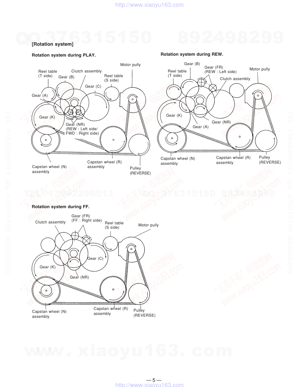
[Rotation system]
Rotation system during PLAY.
Rotation system during REW.
Rotation system during FF.
Gear (C)
Pulley
(REVERSE)
Gear (A)
Reel table
(T side)
Gear (B)
Clutch assembly
Reel table
(S side)
Motor pully
Gear (NR)
(REW : Left side/
FWD : Right side)
Gear (K)
Reel table
(T side)
Clutch assembly
Gear (B)
Gear (FR)
(REW : Left side)
Motor pully
Gear (K)
Gear (NR)
Gear (A)
Capstan wheel (N)
assembly
Pulley
(REVERSE)
Capstan wheel (R)
assembly
Gear (FR)
(FF : Right side) Reel table
(S side)
Motor pully
Clutch assembly
Gear (K)
Gear (C)
Gear (NR)
Capstan wheel (N)
assembly
Capstan wheel (R)
assembly
Capstan wheel (N)
assembly
Capstan wheel (R)
assembly
Pulley
(REVERSE)
www. xiaoyu163. com
QQ 376315150
9
9
2
8
9
4
2
9
8
TEL 13942296513
9
9
2
8
9
4
2
9
8
0
5
1
5
1
3
6
7
3
Q
Q
TEL 13942296513 QQ 376315150 892498299
TEL 13942296513 QQ 376315150 892498299
http://www.xiaoyu163.com
— 6 —
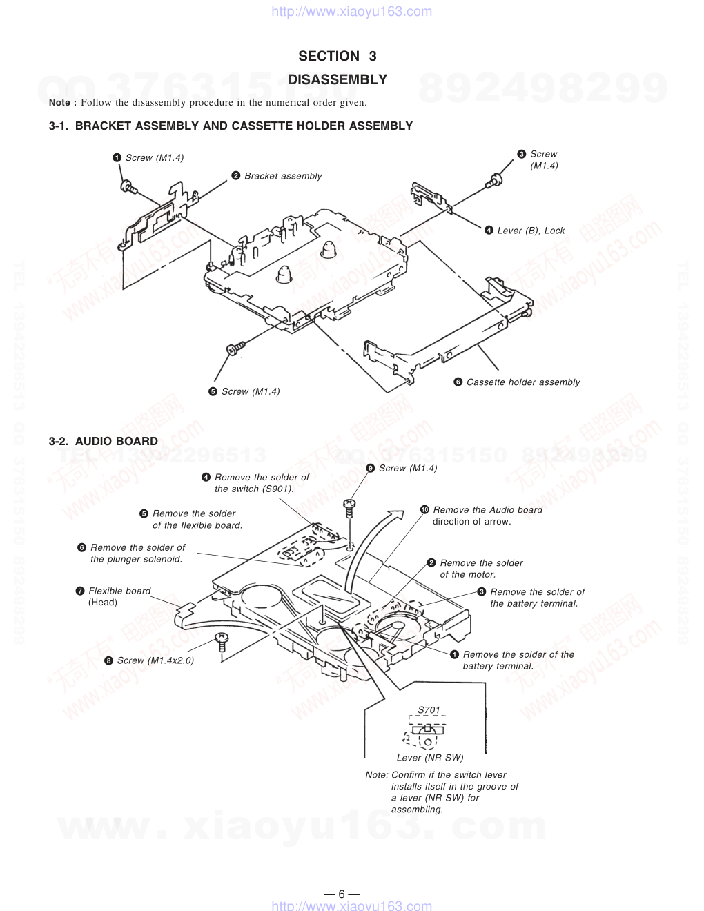
SECTION 3
DISASSEMBLY
Note : Follow the disassembly procedure in the numerical order given.
3-1. BRACKET ASSEMBLY AND CASSETTE HOLDER ASSEMBLY
3-2. AUDIO BOARD
1 Screw (M1.4)
2 Bracket assembly
3 Screw
(M1.4)
4 Lever (B), Lock
5 Screw (M1.4)
6 Cassette holder assembly
1 Remove the solder of the
battery terminal.
3 Remove the solder of
the battery terminal.
2 Remove the solder
of the motor.
4 Remove the solder of
the switch (S901).
5 Remove the solder
of the flexible board.
6 Remove the solder of
the plunger solenoid.
7 Flexible board
(Head)
8 Screw (M1.4x2.0)
9 Screw (M1.4)
S701
Lever (NR SW)
0 Remove the Audio board
direction of arrow.
Note: Confirm if the switch lever
installs itself in the groove of
a lever (NR SW) for
assembling.
www. xiaoyu163. com
QQ 376315150
9
9
2
8
9
4
2
9
8
TEL 13942296513
9
9
2
8
9
4
2
9
8
0
5
1
5
1
3
6
7
3
Q
Q
TEL 13942296513 QQ 376315150 892498299
TEL 13942296513 QQ 376315150 892498299
http://www.xiaoyu163.com
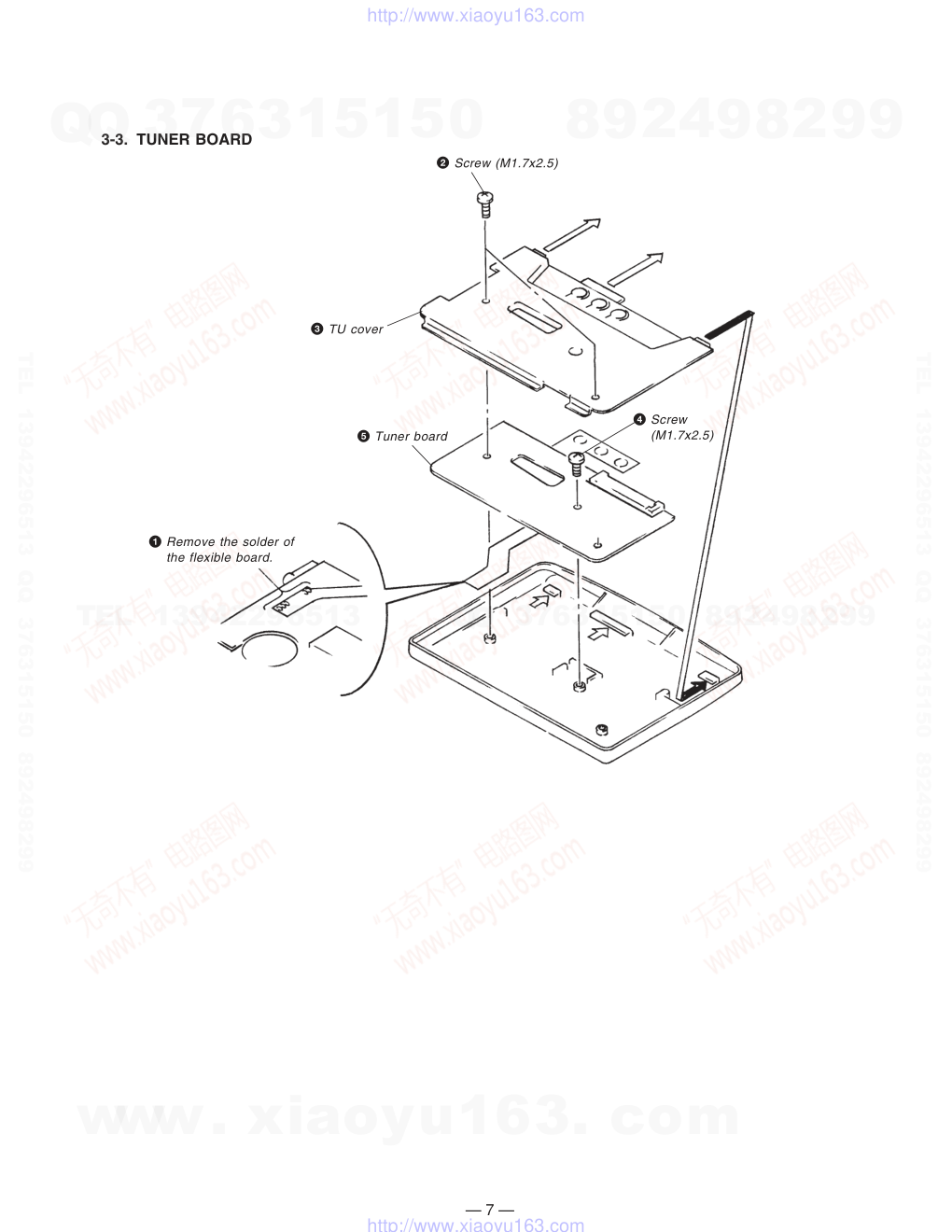
— 7 —
1 Remove the solder of
the flexible board.
2 Screw (M1.7x2.5)
3 TU cover
4 Screw
(M1.7x2.5)
5 Tuner board
3-3. TUNER BOARD
www. xiaoyu163. com
QQ 376315150
9
9
2
8
9
4
2
9
8
TEL 13942296513
9
9
2
8
9
4
2
9
8
0
5
1
5
1
3
6
7
3
Q
Q
TEL 13942296513 QQ 376315150 892498299
TEL 13942296513 QQ 376315150 892498299
http://www.xiaoyu163.com
— 8 —
SECTION 4
ADJUSTMENTS
4-1. MECHANICAL ADJUSTMENTS
PRECAUTION
1.
Clean the following parts with a denatured-alcohol-moistened
swab :
playback head
rubber belts
capstan
pinch roller
2.
Demagnetize the playback head with a head demagnetizer.
3.
Do not use a magnetized screwdriver for the adjustments.
4.
After the adjustments, apply suitable locking compound to the
parts adjusted.
5.
The adjustments should be performed with the rated power
supply voltage (1.3V) unless otherwise noted.
Torque Measurement
Mode
Torque Meter
Meter Reading
CQ-201B
more than 60 g • cm
FWD
FWD
Back Tension
CQ-102C
REV
CQ-102RC
REV
Back Tension
FF
REW
0.5 — 3 g • cm
18 — 33 g • cm
0.5 — 3 g • cm
18 — 33 g • cm
Type
WS-48A
Signal
Used for
3 kHz, 0 dB
Tape Speed Adjustment
16
frequency
counter
+
–
REMOTE jack
set
Test Tape
WS-48A
(3kHz, 0dB)
4-2. ELECTRICAL ADJUSTMENTS
TAPE SECTION
PRECAUTION
1.
Power supply voltage : 1.3V.
2.
Switch position
DOLBY NR switch : OFF
EX DBB switch : NORM
Test Tape
TAPE SPEED ADJUSTMENT
Procedure :
1.
Play back WS-48A (tape center portion) in FWD mode.
Adjust the RV601 so that the frequency counter reads 3,000 ±
30 Hz.
2.
Play back WS-48A (tape center portion) in REV mode.
Confirm that the reading of frequency counter is within 2.5%
from the reading in step 1.
Adjustment Part Location Diagram :
[MAIN BOARD] (SIDE A)
RV601
ND701
www. xiaoyu163. com
QQ 376315150
9
9
2
8
9
4
2
9
8
TEL 13942296513
9
9
2
8
9
4
2
9
8
0
5
1
5
1
3
6
7
3
Q
Q
TEL 13942296513 QQ 376315150 892498299
TEL 13942296513 QQ 376315150 892498299
http://www.xiaoyu163.com
— 9 —
TUNER SECTION
FM SECTION
Setting:
FUNCTION switch
: RADIO
BAND switch
: FM
FM RF SSG
0.01µF
TP (ANT)
TP (GND)
Modulation : 400 Hz, 22.5 kHz dev. (30%)
Output level : as low as possible.
VTVM
(AC : 0.5–5V range)
16
set
REMOTE jack
FM IF ADJUSTMENT
Adjust for a maximum reading on VTVM.
L5
76.00 MHz
FM RF SSG
0.01µF
TP (ANT)
TP (GND)
Adjustment
Element
Frequency
Display
Frequency counter
Reading
RV1
78.00 MHz
19.00 kHz ± 0.05 kHz
VCO ADJUSTMENT
Carrier frequency : 78.00 MHz
Modulation
: no-modulation
Output level
: 55 dB (562 µV)
[TUNER BOARD]
TP
(VCO)
IC3
+
–
frequency
counter
150kΩ
www. xiaoyu163. com
QQ 376315150
9
9
2
8
9
4
2
9
8
TEL 13942296513
9
9
2
8
9
4
2
9
8
0
5
1
5
1
3
6
7
3
Q
Q
TEL 13942296513 QQ 376315150 892498299
TEL 13942296513 QQ 376315150 892498299
http://www.xiaoyu163.com
— 10 —
Digital
voltmeter
TP
(VT)
IC1
+
–
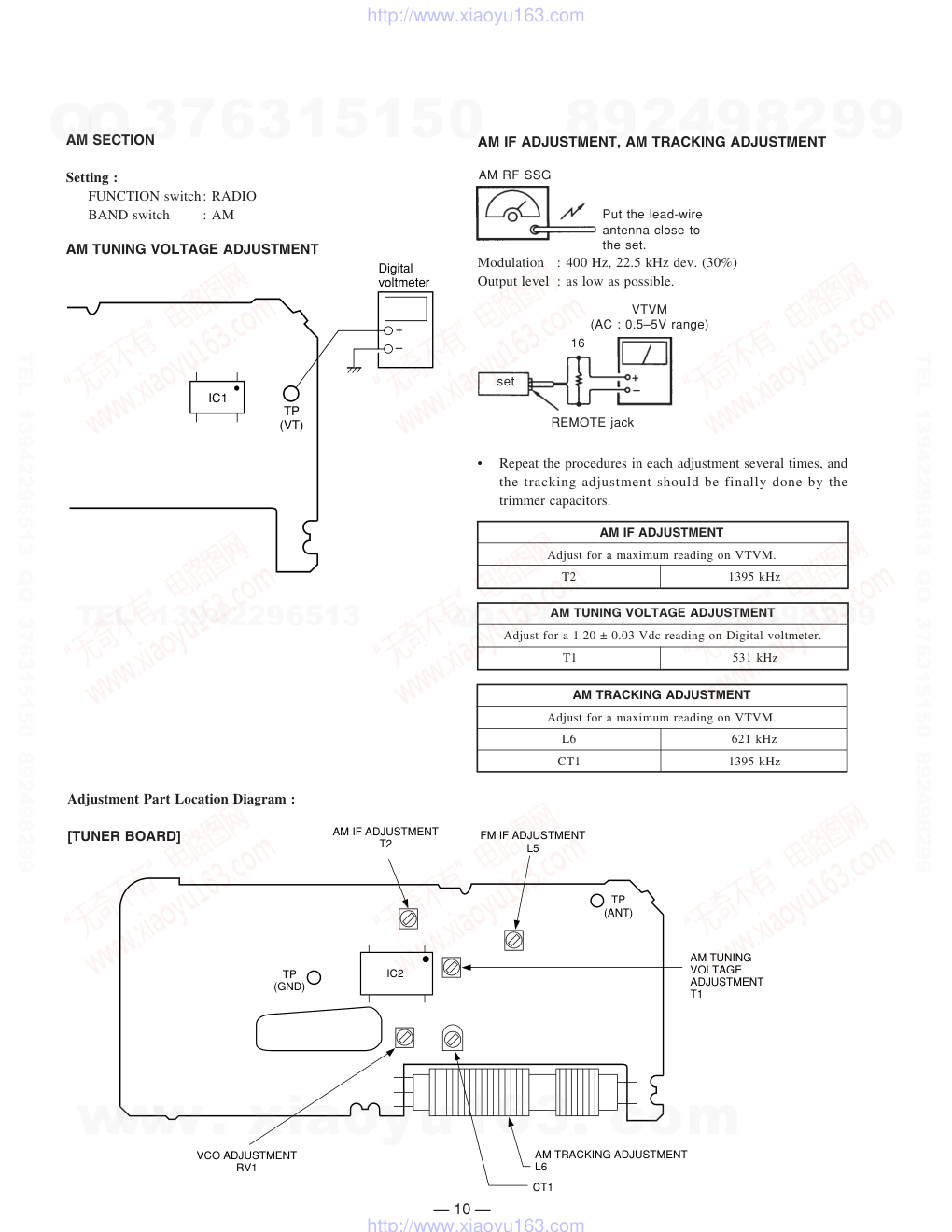
AM RF SSG
Put the lead-wire
antenna close to
the set.
Modulation
: 400 Hz, 22.5 kHz dev. (30%)
Output level : as low as possible.
VTVM
(AC : 0.5–5V range)
16
set
REMOTE jack
AM IF ADJUSTMENT, AM TRACKING ADJUSTMENT
•
Repeat the procedures in each adjustment several times, and
the tracking adjustment should be finally done by the
trimmer capacitors.
Adjustment Part Location Diagram :
[TUNER BOARD]
IC2
TP
(GND)
VCO ADJUSTMENT
RV1
CT1
AM TRACKING ADJUSTMENT
L6
AM TUNING
VOLTAGE
ADJUSTMENT
T1
TP
(ANT)
FM IF ADJUSTMENT
L5
AM IF ADJUSTMENT
T2
AM IF ADJUSTMENT
Adjust for a maximum reading on VTVM.
T2
1395 kHz
AM TUNING VOLTAGE ADJUSTMENT
Adjust for a 1.20 ± 0.03 Vdc reading on Digital voltmeter.
T1
531 kHz
AM TRACKING ADJUSTMENT
Adjust for a maximum reading on VTVM.
L6
621 kHz
CT1
1395 kHz
AM SECTION
Setting :
FUNCTION switch: RADIO
BAND switch
: AM
AM TUNING VOLTAGE ADJUSTMENT
www. xiaoyu163. com
QQ 376315150
9
9
2
8
9
4
2
9
8
TEL 13942296513
9
9
2
8
9
4
2
9
8
0
5
1
5
1
3
6
7
3
Q
Q
TEL 13942296513 QQ 376315150 892498299
TEL 13942296513 QQ 376315150 892498299
http://www.xiaoyu163.com
w w w
.
x i a o y u 1 6 3 .
c o m
Q Q
3 7 6 3 1 5 1 5 0
9
9
2
8
9
4
2
9
8
T E L
1 3 9 4 2 2 9 6 5 1 3
9
9
2
8
9
4
2
9
8
0
5
1
5
1
3
6
7
3
Q
Q
TEL 13942296513 QQ 376315150 892498299
TEL 13942296513 QQ 376315150 892498299
http://www.xiaoyu163.com
w
w
w
.
x
i
a
o
y
u
1
6
3
.
c
o
m
Q
Q
3
7
6
3
1
5
1
5
0
9
9
2
8
9
4
2
9
8
T
E
L
1
3
9
4
2
2
9
6
5
1
3
9
9
2
8
9
4
2
9
8
0
5
1
5
1
3
6
7
3
Q
Q
TEL 13942296513 QQ 376315150 892498299
TEL 13942296513 QQ 376315150 892498299
http://www.xiaoyu163.com
w
w
w
.
x
i
a
o
y
u
1
6
3
.
c
o
m
Q
Q
3
7
6
3
1
5
1
5
0
9
9
2
8
9
4
2
9
8
T
E
L
1
3
9
4
2
2
9
6
5
1
3
9
9
2
8
9
4
2
9
8
0
5
1
5
1
3
6
7
3
Q
Q
TEL 13942296513 QQ 376315150 892498299
TEL 13942296513 QQ 376315150 892498299
http://www.xiaoyu163.com
w
w
w
.
x
i
a
o
y
u
1
6
3
.
c
o
m
Q
Q
3
7
6
3
1
5
1
5
0
9
9
2
8
9
4
2
9
8
T
E
L
1
3
9
4
2
2
9
6
5
1
3
9
9
2
8
9
4
2
9
8
0
5
1
5
1
3
6
7
3
Q
Q
TEL 13942296513 QQ 376315150 892498299
TEL 13942296513 QQ 376315150 892498299
http://www.xiaoyu163.com
— 25 —
BEEP
DDC CTL
MUTE
F/R CTL
DOLBY CTL
DBB ON/OFF
DBB MID/MAX
AVLS CTL
PRE AMP CTL
AMP CTL
REC CTL
PHOTO CTL
LED CTL
PL CTL
M-CTL
M-DIR
M-BRK
TEST
OSC2
OSC1
VDD
XTB
XT
VSS1
VSS2
VCM
VCP
VSSL
HALL1
HALL2
KEY1
KEY2
FOREIGN/JAPAN
A/B
HOLDER
FWD SW
REV SW
RMUM
RQT
DRQT
Beep signal output (TC system=1.6 kHz, CF system=3.0 kHz)
ON/OFF control output of DC-DC converter and amplifier (when DDC on=L)
Audio muting control output (when MUTE ON=L)
Head select output (when FWD=H, when REV=L)
DOLBY ON/OFF control output (when DOLBY ON=L)
Tone control output (when DBB ON=H)
Tone control output (when DBB ON=L)
AVLS ON/OFF control output (when AVLS ON=L)
TC/RADIO select output of preamplifier (when TC=L, when RADIO=H)
Audio amplifier control (when AMP ON=H)
REC control output (when REC=H)
Output for rotation detect intermittent
LED control output (when LED ON=H)
Plunger control output
Motor control output
Motor rotating direction control output
Motor brake control (open)
Test pin (connect to GND)
Resistor connect pin for CR oscillator (800 kHz). (open)
Resistor connect pin for CR oscillator (800 kHz). (open)
Power supply connect terminal
1
2
3
4
5
6
7
8
9
10
11
12
13
14
15
16
17
18
19
20
21
22
23
24
25
26
27
28
29
30
31
32
33
34
35
36
37
38
39
40
O
O
O
O
O
O
O
O
O
O
O
O
O
O
O
O
O
—
—
—
—
—
—
—
—
—
—
—
I
I
I
I
I
I
I
I
I
I
I
I/O
Crystal oscillator connect terminal
Power supply connect terminal
Internal power supply step-up terminal
Internal power supply step-up terminal
Internal power supply step-up terminal
Internal power supply step-up terminal
Rotation detect input
Rotation detect input
Key input
Key input
Mode select input (connect to VDD)
Tape A/B side detection switch input
Holder keying switch (close=L)
MD mode switch (when FWD PLAY=on)
MD mode switch (when REV PLAY=on)
With No remote commander (with=H)
Data request of LCD driver
Communication request output to the remote commader.
Pin No.
Pin Name
I/O
Function
32.768 kHz
5-5. IC PIN FUNCTIONS
• IC701 MSM63120B SYSTEM CONTROL
www. xiaoyu163. com
QQ 376315150
9
9
2
8
9
4
2
9
8
TEL 13942296513
9
9
2
8
9
4
2
9
8
0
5
1
5
1
3
6
7
3
Q
Q
TEL 13942296513 QQ 376315150 892498299
TEL 13942296513 QQ 376315150 892498299
http://www.xiaoyu163.com
— 26 —
Pin No.
Pin Name
I/O
Function
I
O
O
O
I
O
O
O
—
O
I
I
I
I
I
I
Communication to PLL/EEPROM
Communication to PLL/EEPROM
Communication to PLL/EEPROM
Communication to the remote commander
(open)
Communication to the remote commander
Communication to PLL
Communication to EEPROM
Power supply connection terminal
Radio control output (when RADIO=H)
Recording sound detection input (with music=H)
Mode select input (open)
Erasing error detect (FWD) (open)
Erasing error detect (REV) (open)
For power failure stop
Reset terminal
41
42
43
44
45
46
47
48
49
50
51
52
53
54
55
56
TIN
TCLK
TOUT
ROUT
—
RCLK
PERIOD
CS
VDD
RADIO CTL
AMS IN
RADIO PW
N-TUME
R-TUME
SET STOP
RESET
COM2
COM3
SEG1
SEG2
SEG3
SEG4
SEG5
SEG6
SEG8
SEG9
SEG10
SEG11
SEG12
SEG13
SEG14
SEG15
SEG16
SEG17
SEG18
SEG19
1
2
3
4
5
6
7
8
9
10
11
12
13
14
15
16
17
18
19
20
O
O
O
O
O
O
O
O
O
O
O
O
O
O
O
O
O
O
O
O
LCD common signal output
LCD common signal output
LCD segment signal output (not used) (open)
Pin No.
Pin Name
I/O
Function
• IC702 SMC62L3A LCD DRIVE
LCD segment signal output
www. xiaoyu163. com
QQ 376315150
9
9
2
8
9
4
2
9
8
TEL 13942296513
9
9
2
8
9
4
2
9
8
0
5
1
5
1
3
6
7
3
Q
Q
TEL 13942296513 QQ 376315150 892498299
TEL 13942296513 QQ 376315150 892498299
http://www.xiaoyu163.com
— 27 —
Test signal input (connect to GND)
Not used (open)
Clock input for receiver
Not used (open)
Data input for receiver
Not used (open)
Reset signal input
Interruptt signal input for receiver
Hold switch signal input
Input terminal at key pressing in HOLD condition
Not used (open)
Retransmission Request output
Not used (open)
Not used (open)
Not used (open)
Power supply minus terminal (GND)
Power supply plus terminal
CR oscillator input
CR oscillator output
Regulator output
Step-up capacitor connection terminal
Regulator output of LCD system
Step-up output of LCD system
Step-up output of LCD system
Common output of LCD system
Common output of LCD system
Pin No.
Pin Name
I/O
Function
21
22
23
24
25
26
27
28
29
30
31
32
33
34
35
36
37
38
39
40
41
42
43
44
45
46
47
48
TEST
—
RCLK
—
RDATA
NC
RESET
INT
HOLD SW
HOLD KEY
—
RQT
—
—
—
VSS
VDD
OSC1
OSC2
VS1
CA
CB
CC
VL1
VL2
VL3
COM0
COM1
I
I
I
O
I
—
I
I
I
I
I
O
O
O
O
(I)
(I)
I
O
O
—
—
—
O
O
O
O
O
www. xiaoyu163. com
QQ 376315150
9
9
2
8
9
4
2
9
8
TEL 13942296513
9
9
2
8
9
4
2
9
8
0
5
1
5
1
3
6
7
3
Q
Q
TEL 13942296513 QQ 376315150 892498299
TEL 13942296513 QQ 376315150 892498299
http://www.xiaoyu163.com
— 28 —
SECTION 6
EXPLODED VIEWS
NOTE:
• Items marked “*” are not stocked since they
are seldom required for routine service. Some
delay should be anticipated when ordering
these items.
• Color Indication of Appearance Parts Example:
KNOB, BALANCE (WHITE). . . (RED)
Â
Â
Parts color Cabinet’s color
• The mechanical parts with no reference number
in the exploded views are not supplied.
• Hardware (# mark) list and accessories and
packing materials are given in the last of this
parts list.
10
8
9
11
1
A
A
B
B
2
6
17
15
10
5
5
3
4
5
7
10
13
12
14
16
16
L6
6-1. CASE AND TUNER BOARD SECTION
REF.No.
Part No.
Description
Remark
REF.No.
Part No.
Description
Remark
8
X-3371-140-1
ORNAMENT ASSY (SL), REEL...(SILVER,BLUE)
8
X-3371-141-1
ORNAMENT ASSY (B), REEL...(BLACK)
9
3-929-211-01
KNOB (OPEN)
10
3-375-114-21
SCREW (M1.7X2.5)
11
3-929-213-01
COVER, TU
12
A-3016-757-A TUNER BOARD, COMPLETE
13
1-658-180-11
TUNER FLEXIBLE BOARD
14
1-659-355-11
SWITCH UNIT (TU) BOARD
15
3-930-798-01
LOCKER, OPEN
16
3-704-197-13
SCREW(M1.4X2.0), LOCKING...(BLACK)
16
3-704-197-11
SCREW(M1.4X2.0), LOCKING...(SILVER,BLUE)
17
X-3371-069-1
LID ASSY (S), CASSETTE...(SILVER)
17
X-3371-070-1
LID ASSY (L), CASSETTE...(BLUE)
17
X-3371-071-1
LID ASSY (B), CASSETTE...(BLACK)
L6
1-501-815-11
ANTENNA, FERRITE-ROD
1
X-3371-137-1
CASE ASSY (S)...(SILVER)
1
X-3371-138-1
CASE ASSY (L)...(BLUE)
1
X-3371-139-1
CASE ASSY (B)...(BLACK)
2
3-928-077-01
SPRING (HOLD)
3
3-929-216-01
KNOB (HOLD)...(SILVER)
3
3-929-216-11
KNOB (HOLD)...(BLUE)
3
3-929-216-21
KNOB (HOLD)...(BLACK)
4
3-704-197-21
SCREW(M1.4X2.5), LOCKING...(SILVER,BLUE)
4
3-704-197-23
SCREW(M1.4X2.5), LOCKING...(BLACK)
5
3-704-197-31
SCREW(M1.4X3.0), LOCKING...(SILVER,BLUE)
5
3-704-197-33
SCREW(M1.4X3.0), LOCKING...(BLACK)
6
3-929-222-01
PLATE, ORNAMENTAL
7
3-929-218-01
LID, BATTERY CASE...(SILVER)
7
3-929-218-11
LID, BATTERY CASE...(BLUE)
7
3-929-218-21
LID, BATTERY CASE...(BLACK)
www. xiaoyu163. com
QQ 376315150
9
9
2
8
9
4
2
9
8
TEL 13942296513
9
9
2
8
9
4
2
9
8
0
5
1
5
1
3
6
7
3
Q
Q
TEL 13942296513 QQ 376315150 892498299
TEL 13942296513 QQ 376315150 892498299
http://www.xiaoyu163.com
— 29 —
6-2.
AUDIO BOARD SECTION
S901
55
54
58
56
60
61
54
ND701
not
supplied
52
51
53
56
57
59
62
64
62
63
REF.No.
Part No.
Description
Remark
REF.No.
Part No.
Description
Remark
51
A-3016-758-A AUDIO BOARD, COMPLETE
* 52
1-694-030-11
CONDUCTIVE BOARD, CONNECTION
53
1-659-354-11
SWITCH UNIT (AU) BOARD
54
3-704-413-11
SCREW (M1.4)
55
3-704-197-11
SCREW(M1.4X2.0), LOCKING
56
3-375-114-71
SCREW
57
3-928-934-01
TERMINAL BOARD (MINUS),BATTERY
58
3-929-575-01
TERMINAL BOARD, BATTERY
59
X-3371-118-1
TERMINAL BOARD ASSY, BATTERY
60
X-3371-068-1
HOLDER ASSY, CASSETTE
61
3-928-464-01
LEVER (B), LOCK
62
3-366-892-01
SCREW (M1.4)
63
X-3370-961-1
BRACKET ASSY
64
3-933-095-01
COVER, MD
ND701
1-801-100-11
DISPLAY PANEL, LIQUID CRYSTAL
S901
1-762-582-11
SWITCH, LEAF (ATS)
www. xiaoyu163. com
QQ 376315150
9
9
2
8
9
4
2
9
8
TEL 13942296513
9
9
2
8
9
4
2
9
8
0
5
1
5
1
3
6
7
3
Q
Q
TEL 13942296513 QQ 376315150 892498299
TEL 13942296513 QQ 376315150 892498299
http://www.xiaoyu163.com
— 30 —
6-3. MECHANISM SECTION (WM-EX510-112)
105
128
127
REF.No.
Part No.
Description
Remark
REF.No.
Part No.
Description
Remark
101
X-3368-776-1
PINCH LEVER (N) ASSY
102
3-916-341-01
SPRING (PINCH N)
103
3-704-413-31
SCREW (M1.4X7.2)
104
3-916-357-01
GEAR (REEL)
105
3-366-058-01
SPRING, COMPRESSION
106
X-3368-777-1
PINCH LEVER (R) ASSY
107
3-916-342-01
SPRING (PINCH R)
108
3-916-344-01
SPRING (RETURN R)
109
3-928-445-01
DECK, FIXED, TERMINAL
110
X-3370-948-1
CHASSIS ASSY
111
3-366-017-11
BUSHING (CAPSTAN)
112
3-918-943-01
WASHER, STOPPER
113
3-916-350-01
PULLEY (REVERSE)
114
3-916-346-01
SPRING, TENSION
115
X-3370-951-1
CLUTCH ASSY
116
3-928-441-01
SPRING (RETURN N)
117
X-3368-779-1
WHEEL (N) ASSY, CAPSTAN
118
X-3368-778-1
WHEEL (R) ASSY, CAPSTAN
119
3-928-444-01
BELT
120
3-928-442-01
SPRING (LOCK LEVER)
121
3-928-443-01
SPRING (R), TORSION
122
3-365-801-01
TABLE, REEL
123
3-916-353-01
GEAR (A)
124
3-916-352-01
GEAR (FR)
125
3-916-354-01
GEAR (B)
126
3-916-347-01
SPRING (NR), TORSION
127
3-916-339-01
LEVER (NRSW)
128
3-358-455-11
SCREW, PRECISION WASHER HEAD
129
A-3042-517-A GEAR (C) BLOCK ASSY
130
3-348-953-31
WASHER
131
3-916-338-01
LEVER (TRIGGER)
132
3-928-440-01
GEAR (CAM)
133
3-928-439-01
GEAR (K)
134
3-916-348-01
SPRING (TRIGGER), TORSION
135
3-386-694-01
WASHER
136
3-338-645-31
WASHER (0.8-2.5)
HP901
1-500-280-11
HEAD, MAGNETIC (PLAYBACK)
M901
1-698-633-11
MOTOR (REEL/CAPSTAN)
PM901 1-454-674-31
SOLENOID, PLUNGER
122
126
130
131
136
115
129
134
123
PM901
132
133
119
122
121
124
125
120
M901
109
110
108
106
107
105
104
111
104
HP901
103
111
112
112
113
101
114
117
118
135
116
102
135
www. xiaoyu163. com
QQ 376315150
9
9
2
8
9
4
2
9
8
TEL 13942296513
9
9
2
8
9
4
2
9
8
0
5
1
5
1
3
6
7
3
Q
Q
TEL 13942296513 QQ 376315150 892498299
TEL 13942296513 QQ 376315150 892498299
http://www.xiaoyu163.com
— 31 —
• Due to standardization, replacements in the parts
list may be different from the parts specified in
the diagrams or the components used on the set.
• -XX, -X mean standardized parts, so they may
have some difference from the original one.
• Items marked “*” are not stocked since they are
seldom required for routine service. Some delay
should be anticipated when ordering these items.
• RESISTORS
All resistors are in ohms
METAL: Metal-film resistor
METAL OXIDE: Metal Oxide-film resistor
F : nonflammable
• SEMICONDUCTORS
In each case, u: µ , for example:
uA...: µ A..., uPA...: µ PA..., uPB...: µ PB...,
uPC...: µ PC..., uPD...: µ PD...
• CAPACITORS
uF : µ F
• COILS
uH : µ H
The components identified by
mark ! or dotted line with mark
! are critical for safety.
Replace only with part number
specified.
When indicating parts by reference
number, please include the board
name.
SECTION 7
ELECTRICAL PARTS LIST
REF.No.
Part No.
Description
Remark
REF.No.
Part No.
Description
Remark
A-3016-758-A AUDIO BOARD, COMPLETE
*************************
1-659-354-11
SWITCH UNIT (AU) BOARD
*
1-694-030-11
CONDUCTIVE BOARD, CONNECTION
< CAPACITOR >
C101
1-162-964-11
CERAMIC CHIP
0.001uF
10%
50V
C102
1-162-964-11
CERAMIC CHIP
0.001uF
10%
50V
C103
1-162-970-11
CERAMIC CHIP
0.01uF
10%
25V
C104
1-107-823-11
CERAMIC CHIP
0.47uF
10%
16V
C105
1-164-489-11
CERAMIC CHIP
0.22uF
10%
16V
C106
1-164-360-11
CERAMIC CHIP
0.1uF
16V
C107
1-109-996-11
CERAMIC CHIP
1uF
6.3V
C108
1-107-826-11
CERAMIC CHIP
0.1uF
10%
16V
C109
1-162-966-11
CERAMIC CHIP
0.0022uF
10%
50V
C110
1-107-823-11
CERAMIC CHIP
0.47uF
10%
16V
C111
1-104-847-11
TANTAL. CHIP
22uF
20%
4V
C112
1-107-826-11
CERAMIC CHIP
0.1uF
10%
16V
C201
1-162-964-11
CERAMIC CHIP
0.001uF
10%
50V
C202
1-162-964-11
CERAMIC CHIP
0.001uF
10%
50V
C203
1-162-970-11
CERAMIC CHIP
0.01uF
10%
25V
C204
1-107-823-11
CERAMIC CHIP
0.47uF
10%
16V
C205
1-164-489-11
CERAMIC CHIP
0.22uF
10%
16V
C206
1-164-360-11
CERAMIC CHIP
0.1uF
16V
C207
1-109-996-11
CERAMIC CHIP
1uF
6.3V
C208
1-107-826-11
CERAMIC CHIP
0.1uF
10%
16V
C209
1-162-966-11
CERAMIC CHIP
0.0022uF
10%
50V
C210
1-107-823-11
CERAMIC CHIP
0.47uF
10%
16V
C211
1-104-847-11
TANTAL. CHIP
22uF
20%
4V
C212
1-107-826-11
CERAMIC CHIP
0.1uF
10%
16V
C302
1-109-996-11
CERAMIC CHIP
1uF
6.3V
C303
1-135-201-11
TANTALUM CHIP
10uF
20%
4V
C304
1-109-996-11
CERAMIC CHIP
1uF
6.3V
C305
1-162-964-11
CERAMIC CHIP
0.001uF
10%
50V
C306
1-135-201-11
TANTALUM CHIP
10uF
20%
4V
C307
1-104-847-11
TANTAL. CHIP
22uF
20%
4V
C308
1-109-996-11
CERAMIC CHIP
1uF
6.3V
C309
1-109-936-11
TANTAL. CHIP
3.3uF
20%
2.5V
C310
1-109-996-11
CERAMIC CHIP
1uF
6.3V
C311
1-164-360-11
CERAMIC CHIP
0.1uF
16V
C312
1-162-960-11
CERAMIC CHIP
220PF
10%
50V
C313
1-107-823-11
CERAMIC CHIP
0.47uF
10%
16V
C314
1-109-996-11
CERAMIC CHIP
1uF
6.3V
C315
1-164-360-11
CERAMIC CHIP
0.1uF
16V
C316
1-109-996-11
CERAMIC CHIP
1uF
6.3V
C319
1-162-974-11
CERAMIC CHIP
0.01uF
50V
C320
1-107-811-11
TANTAL. CHIP
47uF
20%
4V
C601
1-107-826-11
CERAMIC CHIP
0.1uF
10%
16V
C602
1-164-346-11
CERAMIC CHIP
1uF
16V
C603
1-164-360-11
CERAMIC CHIP
0.1uF
16V
C604
1-164-489-11
CERAMIC CHIP
0.22uF
10%
16V
C605
1-164-360-11
CERAMIC CHIP
0.1uF
16V
C606
1-162-970-11
CERAMIC CHIP
0.01uF
10%
25V
C607
1-162-970-11
CERAMIC CHIP
0.01uF
10%
25V
C608
1-162-970-11
CERAMIC CHIP
0.01uF
10%
25V
C701
1-107-815-11
TANTAL. CHIP
2.2uF
20%
4V
C702
1-109-996-11
CERAMIC CHIP
1uF
6.3V
C703
1-162-915-11
CERAMIC CHIP
10PF
0.5PF
50V
C704
1-113-619-11
CERAMIC CHIP
0.47uF
10V
C705
1-113-619-11
CERAMIC CHIP
0.47uF
10V
C706
1-113-619-11
CERAMIC CHIP
0.47uF
10V
C710
1-164-360-11
CERAMIC CHIP
0.1uF
16V
C711
1-164-360-11
CERAMIC CHIP
0.1uF
16V
C713
1-109-996-11
CERAMIC CHIP
1uF
6.3V
CB701
1-113-945-11
CAPACITOR
0.1uF
< CONNECTOR >
CN301
1-766-642-21 CONNECTOR, FFC/FPC 6P
< DIODE >
D701
8-719-049-09 DIODE
1SS367-T3SONY
D702
8-719-051-00 DIODE
CL-230HR-CD-T (BATT)
D703
8-719-988-62 DIODE
1SS355
< FERRITE BEAD >
FB101
1-500-113-11 BEAD, FERRITE (CHIP)
FB201
1-500-113-11 BEAD, FERRITE (CHIP)
FB301
1-500-113-11 BEAD, FERRITE (CHIP)
FB701
1-233-311-21 INPEDANCE ARRAY, CHIP (4 GANG)
< IC >
IC301
8-759-368-55 IC
BA3612AKV
IC302
8-759-275-48 IC
NJM2185V-TE2
IC601
8-759-356-46 IC
MM1279XVBE
IC701
8-759-366-26 IC
MSM63120B-05GSK
IC702
8-759-360-58 IC
SMC62L3A-T10
IC703
8-759-280-85 IC
PST9010NL
IC704
8-759-524-72 IC
S-29L294-S822
版权声明
1. 本站所有素材,仅限学习交流,仅展示部分内容,如需查看完整内容,请下载原文件。
2. 会员在本站下载的所有素材,只拥有使用权,著作权归原作者所有。
3. 所有素材,未经合法授权,请勿用于商业用途,会员不得以任何形式发布、传播、复制、转售该素材,否则一律封号处理。
4. 如果素材损害你的权益请联系客服QQ:77594475 处理。