索尼SONY DVX-100音响电路原理图
 "索尼SONY DVX-100音响电路原理图-0")
 "索尼SONY DVX-100音响电路原理图-1")
 "索尼SONY DVX-100音响电路原理图-2")
 "索尼SONY DVX-100音响电路原理图-3")
 "索尼SONY DVX-100音响电路原理图-4")
 "索尼SONY DVX-100音响电路原理图-5")
 "索尼SONY DVX-100音响电路原理图-6")
 "索尼SONY DVX-100音响电路原理图-7")
 "索尼SONY DVX-100音响电路原理图-8")
 "索尼SONY DVX-100音响电路原理图-9")
SERVICE MANUAL
DVD CHANGER
US Model
Canadian Model
AEP Model
UK Model
E Model
Chinese Model
SPECIFICATIONS
DVX-100
Ver 1.0 2001.09
9-873-223-01
Sony Corporation
2001I0500-1
e Vehicle Company
C 2001.9
Shinagawa Tec Service Manual Production Group
• DVX-100 is composed of following units.
DVD changer
FM modulator (RF unit)
Wired remote commander (RM-X130)
Wireless remote commander (RM-X120)
Remote control sensor
DVD changer
Laser
Semiconductor laser
Signal format system
For the customers in Europe, China,
Oceania and Asia
PAL
For the customers in the USA, Canada and
Center & South America
NTSC
Audio characteristics
Frequency response
5 Hz to 20 kHz
Signal to noise ratio
90 dB
Harmonic distortion
0.01 %
Dynamic range
90 dB
Wow and flutter
below measurable limits
(±0.001 % W PEAK)
General
Power requirements
12V DC car battery
(negative ground)
Outputs
Audio output
Video output
Digital output
RF signal (FM) output
Inputs
Connector of remote control censor
Power consumption
1 A (during playback)
Dimensions (approx.)
250 × 80 × 205 mm
(w/h/d) incl. projecting parts
Mass (approx.)
2.5 kg
Operating temperature
–10 ˚C to 55 ˚C
Supplied accessories
Wired remote commander (1)
Wireless remote commander (1)
Remote control sensor (1)
Disc magazine (1)
FM modulator (1)
AA (R6) alkaline batteries (2)
Index label (1)
Parts for installation and connections (1 set)
Design and specifications are subject to change without notice.
www. xiaoyu163. com
QQ 376315150
9
9
2
8
9
4
2
9
8
TEL 13942296513
9
9
2
8
9
4
2
9
8
0
5
1
5
1
3
6
7
3
Q
Q
TEL 13942296513 QQ 376315150 892498299
TEL 13942296513 QQ 376315150 892498299
http://www.xiaoyu163.com
2
DVX-100
Notes on chip component replacement
• Never reuse a disconnected chip component.
• Notice that the minus side of a tantalum capacitor may be dam-
aged by heat.
Flexible Circuit Board Repairing
• Keep the temperature of the soldering iron around 270 ˚C dur-
ing repairing.
• Do not touch the soldering iron on the same conductor of the
circuit board (within 3 times).
• Be careful not to apply force on the conductor when soldering
or unsoldering.
NOTES ON HANDLING THE OPTICAL PICK-UP
BLOCK OR BASE UNIT
SAFETY-RELATED COMPONENT WARNING!!
COMPONENTS IDENTIFIED BY MARK 0 OR DOTTED
LINE WITH MARK 0 ON THE SCHEMATIC DIAGRAMS
AND IN THE PARTS LIST ARE CRITICAL TO SAFE
OPERATION. REPLACE THESE COMPONENTS WITH
SONY PARTS WHOSE PART NUMBERS APPEAR AS
SHOWN IN THIS MANUAL OR IN SUPPLEMENTS PUB-
LISHED BY SONY.
CAUTION
Use of controls or adjustments or performance of procedures
other than those specified herein may result in hazardous ra-
diation exposure.
The laser diode in the optical pick-up block may suffer electro-
static break-down because of the potential difference generated
by the charged electrostatic load, etc. on clothing and the human
body.
During repair, pay attention to electrostatic break-down and also
use the procedure in the printed matter which is included in the
repair parts.
The flexible board is easily damaged and should be handled with
care.
NOTES ON LASER DIODE EMISSION CHECK
Never look into the laser diode emission from right avove when
checking it for adustment. It is feared that you will lose your sight.
NOTES ON HANDLING THE OPTICAL PICK-UP BLOCK .
The laser diode in the optical pick-up block may suffer electro-
static break-down easily. When handling it, perform soldering
bridge to the laser-tap on the flexible board. Also perform mea-
sures against electrostatic break-down sufficiently before the op-
eration. The flexible board is easily damaged and should be handled
with care.
OPTICAL PICK-UP FLEXIBLE BOARD
laser-tap
US, Canadian models:
AEP, UK models:
This product is classified as a CLASS 1 LASER PRODUCT.
The CLASS 1 LASER PRODUCT label is located of the rear ex-
terior.
This label is located on the rear exterior.
ATTENTION AU COMPOSANT AYANT RAPPORT
À LA SÉCURITÉ!
LES COMPOSANTS IDENTIFIÉS PAR UNE MARQUE 0
SUR LES DIAGRAMMES SCHÉMATIQUES ET LA LISTE
DES PIÈCES SONT CRITIQUES POUR LA SÉCURITÉ
DE FONCTIONNEMENT. NE REMPLACER CES COM-
POSANTS QUE PAR DES PIÈCES SONY DONT LES
NUMÉROS SONT DONNÉS DANS CE MANUEL OU
DANS LES SUPPLÉMENTS PUBLIÉS PAR SONY.
www. xiaoyu163. com
QQ 376315150
9
9
2
8
9
4
2
9
8
TEL 13942296513
9
9
2
8
9
4
2
9
8
0
5
1
5
1
3
6
7
3
Q
Q
TEL 13942296513 QQ 376315150 892498299
TEL 13942296513 QQ 376315150 892498299
http://www.xiaoyu163.com
3
DVX-100
TABLE OF CONTENTS
1.
SERVICING NOTES ...............................................
4
2.
GENERAL ...................................................................
7
3.
DISASSEMBLY
3-1.
Disassembly Flow ........................................................... 11
3-2.
Cabinet Assy.................................................................... 12
3-3.
Front Panel Assy ............................................................. 12
3-4.
MPEG Board ................................................................... 13
3-5.
MAIN Board ................................................................... 13
3-6.
Mechanism Deck............................................................. 14
3-7.
Top Chassis Assy ............................................................ 14
3-8.
DC Motor Assy (Elevator) (M1)..................................... 15
3-9.
Mechanism Panel Assy, Elevator Section....................... 15
3-10. DC Motor Assy (Loading) (M3) ..................................... 16
3-11. CD Board......................................................................... 16
3-12. DVD Chassis Assy .......................................................... 17
4.
ASSEMBLY
4-1.
Adjusting Phase of A Slide Plate, B Slide Plate,
C Slide Plate and D Slide Plate ...................................... 18
5.
ELECTRICAL ADJUSTMENTS ......................... 19
6.
DIAGRAMS
6-1.
Block Diagram – SERVO Section – .............................. 21
6-2.
Block Diagram – VIDEO/AUDIO Section – ................ 22
6-3.
Block Diagram – MAIN Section – ................................ 23
6-4.
Block Diagram – CONTROL/POWER Section –......... 24
6-5.
Note for Printed Wiring Boards
and Schematic Diagrams ................................................ 25
6-6.
Printed Wiring Boards – SERVO Section – .................. 26
6-7.
Schematic Diagrams – SERVO Section – ..................... 27
6-8.
Printed Wiring Board – MAIN Board (Side A) – ......... 28
6-9.
Printed Wiring Board – MAIN Board (Side B) – ......... 29
6-10. Schematic Diagram – MAIN Section (1/4) – ................ 30
6-11. Schematic Diagram – MAIN Section (2/4) – ................ 31
6-12. Schematic Diagram – MAIN Section (3/4) – ................ 32
6-13. Schematic Diagram – MAIN Section (4/4) – ................ 33
6-14. Printed Wiring Board
– MPEG Board (Component Side) – .............................. 34
6-15. Printed Wiring Board
– MPEG Board (Conductor Side) –................................ 35
6-16. Schematic Diagram – MPEG Section (1/4) – ............... 36
6-17. Schematic Diagram – MPEG Section (2/4) – ............... 37
6-18. Schematic Diagram – MPEG Section (3/4) – ............... 38
6-19. Schematic Diagram – MPEG Section (4/4) – ............... 39
6-20. IC Pin Function Description ........................................... 42
7.
EXPLODED VIEWS
7-1.
Front Panel, Cabinet Section .......................................... 45
7-2.
MPEG Board Section ...................................................... 46
7-3.
Bottom Lid Section ......................................................... 47
7-4.
Mechanism Deck (Top Chassis Section) ........................ 48
7-5.
Mechanism Deck (Front Plate, Slide Plate Section) ...... 49
7-6.
Mechanism Deck (Base Chassis Section) ...................... 50
7-7.
Mechanism Deck (DVD Chassis Section) ..................... 51
7-8.
Mechanism Deck (Elevator Chassis Section) ................ 52
7-9.
Mechanism Deck (Clamp Chassis Section) ................... 53
8.
ELECTRICAL PARTS LIST ............................... 54
www. xiaoyu163. com
QQ 376315150
9
9
2
8
9
4
2
9
8
TEL 13942296513
9
9
2
8
9
4
2
9
8
0
5
1
5
1
3
6
7
3
Q
Q
TEL 13942296513 QQ 376315150 892498299
TEL 13942296513 QQ 376315150 892498299
http://www.xiaoyu163.com
4
DVX-100
SECTION 1
SERVICING NOTES
TEST DISC
This set can playback a CD-R, CD-RW for audio use and DVD.
When test this set, use the following test disc.
Test disc for CD-R: TCD-R082LMT (Part No.: J-2501-063-1)
Test disc for CD-RW: TCD-W082L (Part No.: J-2501-063-2)
Test disc for DVD:
NTSC:
HLX-504 (Part No.: J-6090-088-A) (single layer)
HLX-505 (Part No.: J-6090-089-A) (dual layer)
PAL:
HLX-506 (Part No.: J-6090-077-A) (single layer)
HLX-507 (Part No.: J-6090-078-A) (dual layer)
DISC MAGAZINE GETTING OUT PROCEDURE
ON THE POWER SUPPLY IS OFF
Remove the CABINET ASSY, FRONT PANEL ASSY, MPEG
BOARD and MECHANISM DECK beforehand.
(Refer to DISASSEMBLY 3-2 to 3-4 and 3-6.)
1) Press the lock lever assy in the direction of arrow A.
2) Removal the magazine assy in the direction of arrow B.
Note: Take out the magazine only when the tray is completely within the
magazine. If the disk or tray is sticking out, turn on the power and
eject the magazine.
NOTE FOR TRANSPORTING A SET
When a set is transporting after service is completed, be sure to
put the caution label (9-885-016-81) on the bottom of the set and
fix it with three special screw fixers (9-885-016-80).
Note: Seals may be attached on the holes for special screw fixers.
Remove them completely, then install special screw fixers.
lock lever assy
mechanism deck
A
B
magazine assy
special screw fixer
bottom
caution label
DVD changer
seal
www. xiaoyu163. com
QQ 376315150
9
9
2
8
9
4
2
9
8
TEL 13942296513
9
9
2
8
9
4
2
9
8
0
5
1
5
1
3
6
7
3
Q
Q
TEL 13942296513 QQ 376315150 892498299
TEL 13942296513 QQ 376315150 892498299
http://www.xiaoyu163.com
5
DVX-100
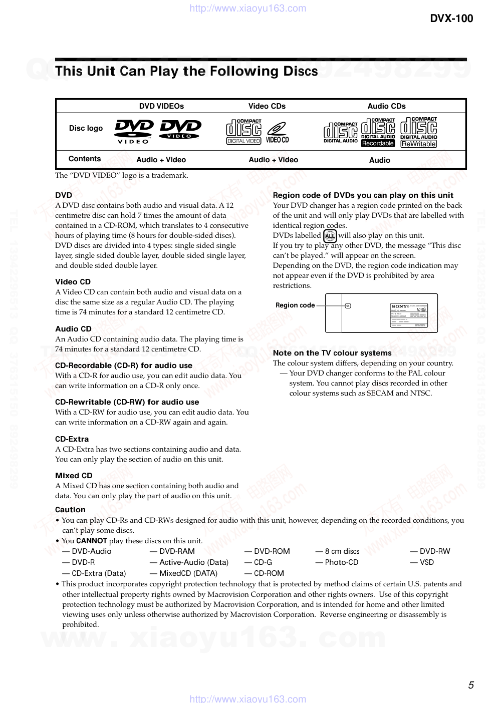
DVD
A DVD disc contains both audio and visual data. A 12
centimetre disc can hold 7 times the amount of data
contained in a CD-ROM, which translates to 4 consecutive
hours of playing time (8 hours for double-sided discs).
DVD discs are divided into 4 types: single sided single
layer, single sided double layer, double sided single layer,
and double sided double layer.
Video CD
A Video CD can contain both audio and visual data on a
disc the same size as a regular Audio CD. The playing
time is 74 minutes for a standard 12 centimetre CD.
Audio CD
An Audio CD containing audio data. The playing time is
74 minutes for a standard 12 centimetre CD.
CD-Recordable (CD-R) for audio use
With a CD-R for audio use, you can edit audio data. You
can write information on a CD-R only once.
CD-Rewritable (CD-RW) for audio use
With a CD-RW for audio use, you can edit audio data. You
can write information on a CD-RW again and again.
CD-Extra
A CD-Extra has two sections containing audio and data.
You can only play the section of audio on this unit.
Mixed CD
A Mixed CD has one section containing both audio and
data. You can only play the part of audio on this unit.
Region code of DVDs you can play on this unit
Your DVD changer has a region code printed on the back
of the unit and will only play DVDs that are labelled with
identical region codes.
DVDs labelled will also play on this unit.
If you try to play any other DVD, the message “This disc
can’t be played.” will appear on the screen.
Depending on the DVD, the region code indication may
not appear even if the DVD is prohibited by area
restrictions.
Note on the TV colour systems
The colour system differs, depending on your country.
— Your DVD changer conforms to the PAL colour
system. You cannot play discs recorded in other
colour systems such as SECAM and NTSC.
Caution
• You can play CD-Rs and CD-RWs designed for audio with this unit, however, depending on the recorded conditions, you
can’t play some discs.
• You CANNOT play these discs on this unit.
— DVD-Audio
— DVD-RAM
— DVD-ROM
— 8 cm discs
— DVD-RW
— DVD-R
— Active-Audio (Data)
— CD-G
— Photo-CD
— VSD
— CD-Extra (Data)
— MixedCD (DATA)
— CD-ROM
• This product incorporates copyright protection technology that is protected by method claims of certain U.S. patents and
other intellectual property rights owned by Macrovision Corporation and other rights owners. Use of this copyright
protection technology must be authorized by Macrovision Corporation, and is intended for home and other limited
viewing uses only unless otherwise authorized by Macrovision Corporation. Reverse engineering or disassembly is
prohibited.
This Unit Can Play the Following Discs
DVD VIDEOs
Disc logo
Contents
Video CDs
Audio CDs
Audio + Video
Audio + Video
Audio
The “DVD VIDEO” logo is a trademark.
ALL
X
10-DISC DVD CHANGER
MODEL NO
DC 12 VOLTS
NEGATIVE GROUND
10
Region code
www. xiaoyu163. com
QQ 376315150
9
9
2
8
9
4
2
9
8
TEL 13942296513
9
9
2
8
9
4
2
9
8
0
5
1
5
1
3
6
7
3
Q
Q
TEL 13942296513 QQ 376315150 892498299
TEL 13942296513 QQ 376315150 892498299
http://www.xiaoyu163.com
6
DVX-100
This Unit Can Play the Following Discs
Note on PBC (Playback Control) (Video CDs)
This player conforms to Ver. 1.1 and Ver. 2.0 of Video CD
standards. You can enjoy two kinds of playback according to the
disc type.
Disc type
Video CDs without
PBC functions
(Ver. 1.1 discs)
Video CDs with
PBC functions
(Ver. 2.0 discs)
Note on DTS-encoded CDs
When playing DTS*-encoded CDs, excessive noise will be heard
from the analog stereo outputs. To avoid possible damage to the
audio system, the consumer should take proper precautions
when the analogue stereo outputs of this DVD changer are
connected to an amplification system. To enjoy DTS Digital
Surround™ playback, an external 5.1-channel DTS Digital
Surround™ decoder system must be connected to the digital
output of this DVD changer.
* “DTS,” “DTS Digital Surround” and “DTS Digital Out” are
trademarks of Digital Theater Systems, Inc.
Note on CD-R/CD-RW
You can play certain CD-Rs and CD-RWs designed for audio use
(provided the quality of the recording is adequate).
— You can play Digital Audio CD-Rs and CD-RWs bearing
these icons:
— You CANNOT play (non-digital audio) CD-Rs and CD-RWs
bearing these icons:
You can
Enjoy video playback (moving
pictures) as well as music.
Play interactive software by using
menu screens displayed on the monitor
(PBC Playback), in addition to the
video playback functions of Ver. 1.1
discs. Moreover, you can play high-
resolution still pictures if they are
included on the disc.
www. xiaoyu163. com
QQ 376315150
9
9
2
8
9
4
2
9
8
TEL 13942296513
9
9
2
8
9
4
2
9
8
0
5
1
5
1
3
6
7
3
Q
Q
TEL 13942296513 QQ 376315150 892498299
TEL 13942296513 QQ 376315150 892498299
http://www.xiaoyu163.com
7
DVX-100
SECTION 2
GENERAL
This section is extracted from
instruction manual.
Location of controls
Wireless remote commander
1 MENU button 30, 33, 34
Press MENU to display the recorded DVD and Video
CD menu.
2 SUBTITLE button 29
Press SUBTITLE to change the subtitle languages
while playing a DVD.
3 AUDIO button
• DVD 31
Press AUDIO to change the Audio Language.
• Video CD/Audio CD 32
Press AUDIO to change the Audio Output Method.
4 REPEAT button
• DVD 19
Press REPEAT to play a title or a chapter repeatedly.
• Video CD/Audio CD 19
Press REPEAT to play the entire tracks of a disc or a
track.
5 AyB (A-B repeat) button
• DVD/Video CD 20
Press AyB to play your favorite scene repeatedly.
• Audio CD 20
Press AyB to play your favorite passage of songs.
6 Number buttons 23, 28, 29, 33, 42, 44, 45
Press the number buttons to input numbers.
7 CLEAR button 23, 28, 29, 33, 42, 44, 45
Press CLEAR to clear the wrong number you entered.
8 Cursor buttons 19, 23, 26, 27, 28, 29, 30, 31, 33, 36,
37, 38, 39, 40, 41, 42, 43, 44, 45, 46, 47
Press the cursor buttons to select the items.
9 SCAN buttons 17, 21
Press M for fast forward playback.
Press m for fast rewind playback.
• DVD/Video CD 21
Press X (PAUSE), then press M/m for slow
playback.
q; PREV/NEXT button 16, 17, 21
Press > to go to the next chapter, track, or scene.
Press . to go back to the previous chapter, track or
scene.
• DVD/Video CD 21
Press X (PAUSE), then press > to play pictures
frame by frame.
qa SET UP button 36, 37, 38, 39, 41, 43, 44, 45, 46, 47
Press SET UP when you want to change the settings,
such as DVD Menu Language, Audio Language,
Subtitle Language, and so on.
qs TITLE button 30
Press TITLE to display the title menu.
qd TIME button 27, 28
Press TIME to display the elapsed/remaining time of
items such as title, chapter, track, and disc.
qf ANGLE button 31
Press ANGLE to select the pictures of a scene viewed
from the multiple angle during a DVD playback.
qg PLAY MODE button 22, 23, 24
• Audio CD
Press PLAY MODE to select your favorite playback
mode.
qh SEARCH button 28, 29
Press SEARCH to specify a desired point on a disc by
title, chapter, track , or time.
qj RETURNO button 26, 27, 36, 37, 38, 39, 41, 42, 43,
44, 45, 46, 47
Press RETURN to come back to the normal playback
mode.
qk ENTER button 23, 24, 26, 27, 28, 29, 30, 31, 32, 33,
37, 38, 39, 40, 41, 42, 43, 44, 45, 46, 47
Press ENTER to execute the items or settings.
ql LIST button 26, 27
Press LIST to display the list of discs contained in the
magazine.
w; DISC (+/–) button 16
Press DISC to select your favorite disc.
wa PLAY button 16, 17, 21, 23, 24, 33, 34, 37, 38, 39, 40,
41, 43, 44, 45, 46, 47
Press PLAY to play a disc.
ws PAUSE button 16, 17, 21
Press PAUSE to pause playback.
wd STOP button 16, 17, 23, 33, 34, 36
Press STOP to stop playback.
Caution
When you want to turn on the unit, you have to press
B/X* on the wired remote commander. See “1 B/X
button” of the wired remote commander (page 10).
* You can also press PLAY on the wireless remote
commander for start-up.
MENU
TITLE
ANGLE
AUDIO
SUB TITLE
TIME
SEARCH
REPEAT
RETURN
CLEAR
PREV
NEXT
SET UP
PAUSE
PLAY MODE
1
2
3
4
5
6
7
8
9
0
LIST
DISC
SCAN
PLAY
STOP
A B
ENTER
1
2
3
4
5
6
7
8
9
q;
qa
ws
wd
qf
qs
qd
qg
qh
w;
qj
qk
ql
wa
Light emitter
www. xiaoyu163. com
QQ 376315150
9
9
2
8
9
4
2
9
8
TEL 13942296513
9
9
2
8
9
4
2
9
8
0
5
1
5
1
3
6
7
3
Q
Q
TEL 13942296513 QQ 376315150 892498299
TEL 13942296513 QQ 376315150 892498299
http://www.xiaoyu163.com
8
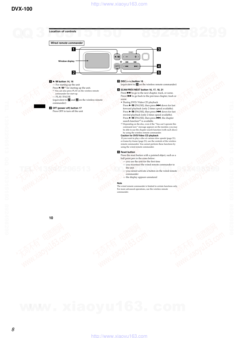
DVX-100
10
1 B/X button 14, 16
— For starting up the unit
Press B/X*1 for starting up the unit.
*1 You can also press PLAY on the wireless remote
commander for start-up.
— PLAY/PAUSE
(equivalent to wa and ws on the wireless remote
commander)
2 OFF (power off) button 17
Press OFF to turn off the unit
DISC
OFF
1
2
3
4
5
Location of controls
Wired remote commander
Window display
3 DISC (–/+) button 16
(equivalent to w; on the wireless remote commander)
4 SCAN/PREV/NEXT button 16, 17, 18, 21
Press > to go to the next chapter, track, or scene.
Press . to go back to the previous chapter, track or
scene.
• During DVD/Video CD playback
Press B/X (PAUSE), then press > down for fast
forward playback (only 2 times speed available).
Press B/X (PAUSE), then press . down for fast
rewind playback (only 2 times speed available).
Press B/X (PAUSE), then press >, the chapter
search function*2 is available.
*2 Depending on the disc, even if the “You can’t operate this
command now” message appears on the monitor, you may
be able to use the chapter search function (with such discs)
by using the wireless remote commander.
Caution for DVD/Video CD playback
If you want to play a disc at various slow speeds (page 21),
or frame-by-frame (page 21), use the controls of the wireless
remote commander. You cannot perform these functions by
using the wired remote commander.
5 Reset button
Press the reset button with a pointed object, such as a
ball point pen in the cases below:
— you use the unit for the first time
— you reconnect the wired remote commander to
the unit
— you cannot activate a button on the wired remote
commander
— the display appears unnatural
Note
The wired remote commander is limited to certain functions only.
For more advanced operations, use the wireless remote
commander.
www. xiaoyu163. com
QQ 376315150
9
9
2
8
9
4
2
9
8
TEL 13942296513
9
9
2
8
9
4
2
9
8
0
5
1
5
1
3
6
7
3
Q
Q
TEL 13942296513 QQ 376315150 892498299
TEL 13942296513 QQ 376315150 892498299
http://www.xiaoyu163.com
DVX-100
9
9
To parking brake swich cord*3
Al cable de conmutación del freno de estacionamiento*3
至停車制動開關導線*3
Car audio with FM tuner*2
Sistema de audio del automóvil
con sintonizador FM*2
帶FM調諧器的汽車音響*2
when connecting second
monitor for the rear seat
Al conectar el segundo
monitor para el asiento
trasero
在後座連接第二個監視器時
Light green
Verde claro
綠燈
VIDEO OUTPUT FRONT
Yellow
Amarillo
黃色
White
Blanco
白色
Fuse (2 A)
Fusible (2 A)
保險絲(5 A)
from the car aerial*1
de la antena del automóvil*1
來自汽車天線*1
qk
qf
q;
*1
INPUT
Light green
Verde claro
綠燈
DVD changer
Cambiador de DVD
DVD 換碟器
Red
Rojo
紅色
Yellow
Amarillo
黃色
Red
Rojo
紅色
Fuse (5 A)
Fusible (5 A)
保險絲(5 A)
Wired remote commander
Mando a distancia alámbrico
有線遙控器
Remote control sensor
Sensor del mando a distancia
遙控傳感器
w; FM modulator
Modulador FM
FM 調制器
side of the DVD changer
lado del cambiador de DVD
DVD 換碟器的側面
VIDEO IN
Monitor*2
Monitor*2
顯示器*2
*1 Aerial connector
An adaptor (optional) may be necessary for your car and car audio
system. In such a case, consult your dealer.
Connecting the car aerial connector
If you do not want to use the FM tuner for audio out, connect the car
aerial to the car audio aerial in directly, and disconnect the FM modulator
w;.
*2 Not supplied
*3 See “Connecting the parking brake cord” on the reverse side for details.
*1 Conector de antena
Es posible que sea necesario utilizar un adaptador (opcional) para el
automóvil y el sistema de audio de éste. En tal caso, consulte con el
proveedor.
Conexión del conector de la antena del coche
Si no desea utilizar el sintonizador de FM para la salida de audio, conecte
la antena del coche directamente a la antena de audio del mismo y
desconecte el modulador FM w;.
*2 No suministrado
*3 Consulte el “Conexión del cable del freno de estacionamiento” en la cara
inversa para obtener información detallada.
*1 天線連接器
您的汽車和汽車音響系統可能須用一個轉接器(選購件)。此時,請洽詢您購
買產品的銷售店。
連接汽車天線連接器
如果您不想使用 FM 調諧器進行音頻輸出,請將汽車天線直接連接至汽車音響
天線,並斷開FM調制器 w; 的連接。
*2 非附送
*3 詳細情況請參見反面“ 連接停車制動導線” 。
2
1
2
3
VIDEO IN
AUDIO IN
AUDIO IN
AERIAL IN
Monitor*2
Monitor*2
顯示器*2
VIDEO OUTPUT REAR
Yellow
Amarillo
黃色
RCA pin cord*2
Cable con clavijas RCA*2
RCA 針形插頭電線*2
C
A
6 m
5 m
0.6 m
0,6 m
0.6 m
0,6 m
ql
1.5 m
1,5 m
5 m
B
5 m
1 m
1 m
1 m
Black
Negro
黑色
Precauciones
•Esta unidad está diseñada para funcionar
únicamente con una toma a tierra CC de 12V
negativa.
•Antes de realizar las conexiones, desactive el
encendido del automóvil para evitar
cortocircuitos.
•Conecte los conductores de entrada de
alimentación amarillo y rojo solamente
después de haber conectado todos los demás.
•Cerciórese de conectar el conductor de
entrada de alimentación rojo a un terminal de
alimentación de 12 V positivo que se alimente
al poner el interruptor de encendido en la
posición para accesorios.
•Conecte todos los conductores de masa a
un punto común.
•Para su seguridad, el monitor conectado al
cable VIDEO OUTPUT FRONT (salida de
vídeo frontal) sólo se podrá visualizar cuando
el automóvil esté detenido y se haya aplicado
el freno de estacionamiento.
Asegúrese de conectar el cable de
estacionamiento qk al cable de conmutación
del freno de estacionamiento.
Notas sobre el cable de suministro de
alimentación (amarillo)
•Cuando conecte esta unidad en combinación
con otros componentes estéreo, la capacidad
nominal del circuito conectado del automóvil
debe ser superior a la suma de los fusibles de
cada componente.
•Si no hay circuitos del automóvil con
capacidad nominal suficientemente alta,
conecte la unidad directamente a la batería.
Lista de componentes (1)
Los números de la lista corresponden a los de
las instrucciones.
Diagrama de conexión (2)
1 a un punto metálico del automóvil
Conecte en primer lugar el conductor de puesta a
masa negro y, después, los conductores de entrada
de alimentación amarillo y rojo.
2 a un terminal de +12 V que esté permanentemente
alimentado
Asegúrese de conectar en primer lugar el
conductor de puesta a masa negro.
3 a un terminal de +12 V que se alimente al poner el
interruptor de encendido en la posición para
accesorios
Asegúrese de conectar en primer lugar el
conductor de puesta a masa negro.
Las conexiones de salida de audio en esta
unidad se pueden configurar de varias
maneras. Consulte el número de ilustración que
corresponda arriba.
A Para la salida de audio del sistema de audio del
automóvil con sintonizador FM.
Conecte el modulador FM al sistema de audio del
automóvil.
B Para la salida de audio del sistema de audio del
automóvil.
Conecte el cable con clavijas tipo RCA o el
selector de fuente, etc.
C Para la salida de audio del amplificador digital o
dispositivo de audio.
Conecte el cable óptico RC-97/98 (opcional) etc. a
un amplificador digital o dispositivo de audio
equipado con un decodificador digital Dolby.
Sustitución del fusible
Si el fusible se funde, verifique la conexión de
alimentación y sustitúyalo. Si una vez sustituido
vuelve a fundirse, puede deberse a un
funcionamiento interno defectuoso.
Precaución
Emplee un fusible del amperaje especificado.
El uso de un fusible de amperaje superior puede
provocar daños graves.
注意
•本機只能使用負極接地 12 V DC 電源。
•連接線路之前,關閉汽車點火裝置以免引起短
路。
•黃色和紅色的電源輸入導線,必須在其它所有
線路都接完後才可以連接。
•紅色電源線必須連接到當汽車點火鑰匙被轉到
輔助位置時才呈通電狀態的正 12 V 電源接頭。
•所有接地線都必須連接到一共同接地點。
•為了安全,您只能在停車時並使用了停車製動
後,才能觀看連接在 VI DEO OUTPUT FRONT 電
纜上的監視器。
請確信將停車制動導線 qk 連接至汽車的停車
製動開關導線。
電源導線須知(黃色)
•將本機與其它立體聲裝置一起連接使用時,所
連接的汽車電路額定值必須大於所有個裝置保
險絲容量的總和。
•當汽車電路額定值不夠大時,請將本機直接與
電池相連接。
零件一覽表(1)
圖示數字與說明書中的數字是一致的。
線路連接圖(2)
1 至汽車金屬部份
首先連接黑色地線,然後連接黃色和紅色電源輸
入導線。
2 至始終處於通電狀態的 +12 V 電源接頭
務請首先連接黑色地線。
3 至 +12 V 電源接頭,當汽車點火開關處於輔助位
置時此端子才呈通電狀態。
務請首先連接黑色地線。
本裝置的音頻輸出連接有以下幾種方式。請參
見上面對應號碼的圖示。
A 從帶 FM 調制器的汽車音響輸出。
將 FM 調制器連接到汽車音響。
B 從汽車音響輸出。
將 RCA 針形導線連接至汽車音響或音源選擇器等
裝置。
C 從數碼放大器或音頻裝置輸出。
將光纜 RC- 97/98(選購件)等連接到數碼放大器
或帶杜比數碼解碼器的音頻裝置。
更換保險絲
若保險絲燒斷了,請先檢查電源線的連接情況
正常與否,然後才更換保險絲。更換以後,如
果保險絲又燒斷了,則可能是機內有故障。
警告
請使用指定的額定安培數的保險絲。
使用超過額定值的保險絲可能會引起嚴重損
傷。
w w w
.
x i a o y u 1 6 3 .
c o m
Q Q
3 7 6 3 1 5 1 5 0
9
9
2
8
9
4
2
9
8
T E L
1 3 9 4 2 2 9 6 5 1 3
9
9
2
8
9
4
2
9
8
0
5
1
5
1
3
6
7
3
Q
Q
TEL 13942296513 QQ 376315150 892498299
TEL 13942296513 QQ 376315150 892498299
http://www.xiaoyu163.com
DVX-100
10
10
R
8
7
7
5
6
5
3
8
7
8
7
4
6
使用前注意事項
•請注意下列各點仔細選擇合適的安裝位
置:
— 不要把機器安裝在:
• 周圍溫度超過 55 ℃ 的地方。
• 直接照射到陽光的地方或暴露在加熱
器的熱氣中。
• 暴露於雨中、水中、或高濕處。
• 極多塵埃的地方。
• 會受到過大震動的地方。
— 不可讓攻絲螺釘傷到油箱。
— 要安裝機器的位置底下,不可有配電線
或配管。
— 螺絲釘或機器本身切勿傷及或妨礙行李
箱裡或下面的備用輪胎、工具或其他裝
置。
註
• 安裝時,只可以使用附帶的零件以確保安全和穩
固的安裝。
• 在確認安裝面反側無其他導線等物後,方可鑽開
數個直徑為 3. 5 mm 的小孔。
卸下螺絲 ( 3)
•本裝置底部的三個螺絲僅為運輸之用,安
裝前應先將其拆下。
•用封貼 qa 將所有安裝中不需要的孔和用
於運輸的三個螺絲孔封住。封貼可以防止
灰塵進入而造成故障。
註
將三個用於運輸的螺絲保存好,不要遺失。
連接停車制動導線 ( 4)
務必將停車導線 qk(綠燈)連接至停車制
動開關導線上。停車制動開關導線的安裝位
置視您的汽車而定。詳細情況請向您的汽車
經銷商或就近向 Sony 經銷商咨詢。
使用分接頭
用分接頭 ql 連接停車導線 qk(綠燈)的
末端和停車制動開關導線。
註
如果停車制動開關導線很細,可不用分接頭 ql
而直接將停車導線 qk 連接至停車制動開關導
線。
ø3.5 mm
ø3,5 mm
7
7
7
7
2
9
9
5
Example: Horizontal installation
Ejemplo: Instalación horizontal
示例: 水平安裝
Suspended installation
Instalación suspendida
懸掛安裝
45º installation
Instalación 45º
45° 安裝
7
7
6
5
6
5
1
8
7
8
7
2
7
6
5
6
5
3
8
7
8
7
4
7
Remove the DVD changer.
Extraiga el cambiador de DVD.
拆卸 DVD 換碟器。
Precaution
• Choose the mounting location carefully,
observing the following:
— Do not install the unit where;
• the ambient temperature exceeds
55 °C.
• it will be exposed to direct sunlight or
hot air from a heater.
• it will be exposed to rain, water, or
high humidity.
• it will be exposed to a lot of dust.
• it will be subject to excessive
vibration.
— The fuel tank should not be damaged by
the tapping screws.
— There should be no wire harnesses or
pipelines under the place where you are
going to install the unit.
— The spare tyre, tools or other equipment
in or under the trunk should not be
interfered with or damaged by the
screws or the unit itself.
Notes
• Be sure to use only the supplied mounting
hardware for a safe and secure installation.
• Make holes of ø3.5 mm only after making sure
there is nothing on the other side of the
mounting surface.
Removing the screws (3)
• On the bottom of this unit are three screws
for shipping purpose only. Be sure to
remove them before installing.
• Place the seals qa over any holes not used
for installation and the three screws used
for shipping. These seals help to prevent
dust building up, which could cause a
malfunction.
Note
Keep the three screws for shipping purpose, it
will not get lost.
Connecting the parking brake
cord (4)
Be sure to connect the parking cord qk (light
green) to the parking brake switch cord. The
mounting position of the parking brake
switch cord depends on your car, please
consult your car dealer or your nearest Sony
dealer for further details.
6
qa
qa
Precauciones
•Elija cuidadosamente el lugar de montaje
teniendo en cuenta lo siguiente:
— No instale la unidad donde;
•la temperatura ambiente sea superior a
55 °C.
•quede expuesta a la luz solar directa o al
aire caliente de un calefactor.
•quede expuesta a lluvia, agua o mucha
humedad.
•quede expuesta a polvo excesivo.
•quede sujeta a vibraciones excesivas.
— El depósito de combustible no deberá
dañarse con los tornillos autorroscantes.
— No deberá haber cables ni tubos debajo del
lugar en el que vaya a instalar la unidad.
— Ni los tornillos ni la propia unidad
deberían dañar o interferir con la rueda de
repuesto, las herramientas o demás
equipos del portaequipajes o situados
debajo de éste.
Notas
• Para realizar una instalación firme y segura,
cerciórese de utilizar solamente la ferretería de
montaje suministrada.
• Antes de hacer los orificios de ø3,5 mm,
compruebe que no haya nada en el otro lado de la
superficie de montaje.
Retirar los tornillos (3)
•En la parte inferior de esta unidad hay tres
tornillos que sólo se usan por motivos de
transporte. Asegúrese de extraerlos antes de
realizar la instalación.
•Coloque los sellos qa sobre cualquier orificio
que no se utilice para la instalación y los tres
tornillos usados para el transporte. Estos sellos
ayudan a evitar que se acumule polvo, lo que
podría resultar en un funcionamiento
defectuoso.
Nota
Guarde los tres tornillos para el transporte para no
perderlos.
Conexión del cable del freno de
estacionamiento (4)
Asegúrese de conectar el cable de freno de
estacionamiento qk (verde claro) al cable de
conmutación del freno de estacionamiento. La
posición de montaje del cable de conmutación
del freno de estacionamiento depende de cada
automóvil. Consulte el diagrama de conexión
del sistema más adelante y con el concesionario
automovilístico o con el proveedor Sony más
próximo para obtener información detallada.
Using the tap
Attach to the tap ql the end of the parking
cord qk (light green) and the parking brake
switch cord.
Note
If the parking brake switch cord is too thin,
connect the parking cord qk to the parking brake
switch cord directly without using the tap ql.
FM modulator (5)
(For audio out from the car audio with FM
tuner.)
•You can listen to the FM tuner of your car
audio using the audio player of this unit. If
a clear signal cannot be obtained on 88.9
MHz (factory setting), change the position
of the frequency select switch of the FM
modulator to 88.3 MHz.
Use a screw driver to change the position of
the frequency select switch.
•After checking the frequency, use the
cleaning cloth qj to wipe the surface where
the velcro tape wa will be applied, then dry
it completely before installing. Be sure to
install it in a position that will not interfere
with driving.
Wired remote commander
(6)
Use the cleaning cloth qj to wipe the surface
where the velcro tape will be applied, then
dry it completely before installing. Be sure to
install it in a position that will not interfere
with driving.
Wireless remote commander
(7)
Use the cleaning cloth qj to wipe the surface
where the velcro tape wa will be applied, then
dry it completely before installing. Be sure to
install it in a position that will not interfere
with driving.
Example: Horizontal installation
Ejemplo: Instalación horizontal
示例: 水平安裝
Carpet
Moqueta
地毯
H
V
45°
H
V
45°
H
V
45°
H
V
45°
H
V
45°
H
V
45°
qs
qs
Horizontal installation
Instalación horizontal
水平安裝
Vertical installation
Instalación vertical
垂直安裝
9
Vertical installation: “V”
Instalación vertical: “V”
垂直安裝: "V"
45º installation: “45º”
Instalación 45º: “45º”
45° 安裝: "45° "
3
B-1
C-1
15º
Back of the wired remote commander
Parte posterior del mando a distancia alámbrico
有線遙控器的背面
Remote control sensor (8)
•Before installing the remote control sensor,
confirm the maximum signal distance of
remote control. The remote control can be
used up to approximately 3 m from the
light sensor, in a conical area spreading
roughly 15º from the light sensor.
•Use the cleaning cloth qj to wipe the
surface where the velcro tape qh will be
applied, then dry it completely before
installing. Be sure to install it in a position
that will not interfere with driving.
•If necessary, secure the remote control
sensor cord with the cord clamp qg.
How to install the DVD
changer (9)
When you install the DVD changer, be
careful not to damage wiring or equipment
on the other side of the mounting surface.
Before installing the DVD changer
(9 A)
•Before installing this unit, set the built-in
anti-vibration board as illustrated,
depending on the angle.
•After setting the angle, place the seals qs
over any holes on the side of this unit.
These seals help to prevent dust building
up, which could cause a malfunction.
Note for vertical installation (9 B-1)
Before installing in the vertical position, pass
the cable q; through the hole at the lower left
of the bracket 4.
When the unit is to be installed under
the rear tray or in the trunk, observe
the following. (9 C)
•Choose the mounting location carefully so
that the unit can be installed horizontally.
•Make sure the unit does not hinder the
action of the torsion bar spring, hinge, etc.
of the deck lid.
Note
Make installation holes in the rear dash, after
making sure there is nothing obstructing.
Uso del conector intermedio
Conecte al conector intermedio ql el extremo
del cable de estacionamiento qk (verde claro) y
el cable de conmutación del freno de
estacionamiento.
Nota
Si el cable de conmutación del freno de
estacionamiento es demasiado fino, conecte el
cable de estacionamiento qk directamente al cable
del freno de estacionamiento sin utilizar el
conector intermedio ql.
Modulador FM (5)
(Para la salida de audio del sistema de audio
del automóvil con sintonizador FM.)
•El sintonizador FM del sistema de audio del
automóvil se puede escuchar usando el
reproductor de audio de esta unidad. Si no se
puede obtener una señal nítida a 88,9 MHz
(ajuste de fábrica), cambie a 88,3 MHz la
posición del interruptor de selección de
frecuencia situado en el modulador FM.
Utilice un destornillador para cambiar la
posición del interruptor de selección de
frecuencia.
•Después de comprobar la frecuencia, use el
paño de limpieza qj para limpiar la superficie
donde se aplicará la cinta de velcro wa. Luego
déjela secar completamente antes de aplicar la
cinta. Asegúrese de aplicarla en una posición
que no afecte la manera de conducir.
Mando a distancia alámbrico
(6)
Use el paño de limpieza qj para limpiar la
superficie donde se aplicará la cinta de velcro.
Luego déjela secar completamente antes de
aplicar la cinta. Asegúrese de aplicarla en una
posición que no afecte la manera de conducir.
Mando a distancia inalámbrico
(7)
Use el paño de limpieza qj para limpiar la
superficie donde se aplicará la cinta de velcro
wa. Luego déjela secar completamente antes de
aplicar la cinta. Asegúrese de aplicarla en una
posición que no afecte la manera de conducir.
Sensor del mando a distancia
(8)
•Antes de instalar el sensor de mando a
distancia, confirme su distancia máxima de
señal. El mando a distancia se puede usar
hasta una distancia máxima de señal de 3 m
del sensor de luz y dentro de un área cónica
que se extiende aproximadamente 15º del
sensor de luz.
•Use el paño de limpieza qj para limpiar la
superficie donde se aplicará la cinta de velcro
qh. Luego déjela secar completamente antes
de aplicar la cinta. Asegúrese de aplicarla en
una posición que no afecte la manera de
conducir.
•Si fuera necesario, fije el cable de sensor del
mando a distancia utilizando la presilla del
cable qg.
Forma de instalar el cambiador
de DVD (9)
Cuando instale el cambiador de DVD,
cerciórese de no dañar el cableado ni los
equipos que puedan encontrarse en la otra
parte de la superficie de montaje.
Antes de la instalación del cambiador de
DVD (9 A)
•Antes de instalar esta unidad, configure el
tablero antivibración incorporado tal y como
se indica en la ilustración, según el ángulo.
•Una vez configurado el ángulo, coloque los
sellos qs sobre los orificios de la parte lateral
de esta unidad. Estos sellos ayudan a evitar
que se acumule polvo, lo que podría resultar
en un funcionamiento defectuoso.
Nota sobre la instalación vertical (9 B-1)
Antes de instalar el cargador en posición
vertical, pase el cable q; por el orificio de la
parte inferior derecha de la escuadra 4.
Cuando vaya a instalar la unidad debajo
de la bandeja trasera o en el
portaequipajes, tenga en cuenta lo
siguiente. (9 C)
• Elija cuidadosamente el lugar de montaje de
forma que la unidad pueda instalarse
horizontalmente.
• Asegúrese de que la unidad no dificulta la
acción del resorte de la barra de torsión, la
bisagra, etc. de la tapa de la platina.
Nota
Perfore los agujeros de instalación en el salpicadero
posterior, asegurándose de que no haya ningún
obstáculo.
1
4
7
FM 調制器 ( 5)
( 從帶 FM 調諧器的汽車音響輸出。)
•您可以用本裝置的音頻播放機來收聽汽車
音響的 FM 調諧器。如果無法在 88. 9
MHz(出廠設定)獲得清晰的訊號,請將
FM 調制器的頻率選擇開關位置改變到
88. 3 MHz。
用螺絲起子改變頻率選擇開關的位置。
•查對頻率後,用乾淨的軟布 qj 擦拭要貼
上魔術貼 wa 的表面,待完全乾後再安
裝。請確信安裝位置不會影響駕駛。
有線遙控器 ( 6)
用乾淨的軟布 qj 擦拭要貼上魔術貼的表
面,待完全乾後再安裝。請確信安裝位置不
會影響駕駛。
無線遙控器 ( 7)
用乾淨的軟布 qj 擦拭要貼上魔術貼 wa 的
表面,待完全乾後再安裝。請確信安裝位置
不會影響駕駛。
遙控傳感器 ( 8)
•在安裝遙控傳感器前,請先確認最大遙控
訊號距離。遙控器最遠可在距傳感器燈約
3 米,從傳感器燈起以大約 15° 角圓錐
形發散的區域內使用。
•用乾淨的軟布 qj 擦拭要貼上魔術貼 qh
的表面,待完全乾後再安裝。請確信安裝
位置不會影響駕駛。
•如有需要,可用導線夾 qg 將遙控傳感器
導線固定住。
Parking brake switch cord
Cable de conmutación del
freno de estacionamiento
停車制動開關導線
Back of the wireless remote commander
Parte posterior del mando a distancia inalámbrico
無線遙控器的背面
q;
c
5
qd
Place the seal qd.
Coloque el sello qd.
粘上封貼 qd。
Parking brake switch cord
Cable de conmutación del
freno de estacionamiento
停車制動開關導線
Foot brake type
Tipo de freno de pie
腳(踏)剎車型
Hand brake type
Tipo de freno de mano
手(拉)剎車型
ql
Suspended installation: “H”
Instalación suspendida: “H”
懸掛安裝: "H"
H
V
45°
H
V
45°
Remote control sensor
Sensor del mando a distancia
遙控傳感器
qh
Screw driver
Destornillador
螺絲起子
w;
wa
qk
Light sensor
Sensor de luz
傳感器燈
Wireless remote
commander
Mando a distancia
inalámbrico
無線遙控器
Light sensor
Sensor de luz
傳感器燈
Almost 3 m
Casi 3 m
約 3 米
9
B-2
B-3
B-4
B-5
C-2
C-3
15º
wa
c
9
x
x
1
2
3
x
Example: Horizontal installation
Ejemplo: Instalación horizontal
示例: 水平安裝
A
Horizontal installation: “H”
Instalación horizontal: “H”
水平安裝: "H"
Parking brake switch cord
Cable de conmutación del
freno de estacionamiento
停車制動開關導線
如何安裝 DVD 換碟器 ( 9)
安裝 DVD 換碟器時,不可傷及安裝處反面的
配電線或其他設備。
安裝 DVD 換碟器前 ( 9 A)
•安裝本裝置前,請根據角度,按照圖示安
置內置防震板。
•設定角度後,用封貼 qs 將本裝置側面的
所有孔封住。這些封貼能防止灰塵進入裝
置而造成故障。
垂直安裝注意事項 ( 9 B- 1)
在垂直安裝之前,請將電纜 q; 穿過位於支
架 4 左下方的孔。
要把本機安裝在行李箱中或後支架下面
時﹐ 請注意下列事項。 ( 9 C)
•仔細選擇安裝位置,以使本機能保持水平
安裝。
•請確認本機器不會妨礙車箱蓋的扭桿彈
簧、鉸鏈等的動作。
註
在確信沒有任何障礙物後,在汽車後隔板內鑽安
裝孔。
Using the tap
Uso del conector intermedio
使用分接頭
w w w
.
x i a o y u 1 6 3 .
c o m
Q Q
3 7 6 3 1 5 1 5 0
9
9
2
8
9
4
2
9
8
T E L
1 3 9 4 2 2 9 6 5 1 3
9
9
2
8
9
4
2
9
8
0
5
1
5
1
3
6
7
3
Q
Q
TEL 13942296513 QQ 376315150 892498299
TEL 13942296513 QQ 376315150 892498299
http://www.xiaoyu163.com
DVX-100
11
• This set can be disassembled in the order shown below.
SECTION 3
DISASSEMBLY
3-3.
FRONT PANEL ASSY
(Page 12)
3-2.
CABINET ASSY
(Page 12)
3-7.
TOP CHASSIS ASSY
(Page 14)
3-11. CD BOARD
(Page 16)
3-12. DVD CHASSIS ASSY
(Page 17)
3-8.
DC MOTOR ASSY
(ELEVATOR) (M1)
(Page 15)
3-10. DC MOTOR ASSY
(LOADING) (M3)
(Page 16)
3-9.
MECHANISM PANEL ASSY,
ELEVATOR SECTION
(Page 15)
3-4.
MPEG BOARD
(Page 13)
3-5.
MAIN BOARD
(Page 13)
3-6.
MECHANISM DECK
(Page 14)
SET
Note 1: The process described in can be performed in any order.
Note 2: Without completing the process described in , the next process can not be performed.
3-1.
DISASSEMBLY FLOW
www. xiaoyu163. com
QQ 376315150
9
9
2
8
9
4
2
9
8
TEL 13942296513
9
9
2
8
9
4
2
9
8
0
5
1
5
1
3
6
7
3
Q
Q
TEL 13942296513 QQ 376315150 892498299
TEL 13942296513 QQ 376315150 892498299
http://www.xiaoyu163.com
DVX-100
12
3-3.
FRONT PANEL ASSY
Note: Follow the disassembly procedure in the numerical order given.
3-2.
CABINET ASSY
1 four screws
(BTT2.6 × 5)
1 screw
(BTT2.6 × 5)
4 claw
4 claw
4 four claws
4 two claws
2 three claws
1 screw
(BTT2.6 × 5)
5 cabinet assy
3 two bosses
2 two claws
3 front panel assy
1 three claws
2 two claws
www. xiaoyu163. com
QQ 376315150
9
9
2
8
9
4
2
9
8
TEL 13942296513
9
9
2
8
9
4
2
9
8
0
5
1
5
1
3
6
7
3
Q
Q
TEL 13942296513 QQ 376315150 892498299
TEL 13942296513 QQ 376315150 892498299
http://www.xiaoyu163.com
DVX-100
13
3-4.
MPEG BOARD
3-5.
MAIN BOARD
1 two screws
(BTT2.6 × 5)
8 lug assy
6 lug assy
7 four screws
(BTT2.6 × 5)
3 40P-120 mm wire
(CS551)
4 10P 180 mm harness wire
(CS553)
9 MPEG board
4 10P 180 mm harness wire
(CS552)
5 two screws
(BTT2.6 × 5)
2 rear chassis assy
1 two screws
(BTT2.6 × 5)
5 screw
(PTT2 × 4)
5 four screws
(M2 × 2.5)
8 pressure welding cord
(2P-160 mm) (CS303)
0 pressure welding cord (5P-100 mm)
(CS302)
qa main board
9 10P 180 mm harness wire
(CS301)
9 10P 180 mm harness wire
(CS202)
1 screw (M2 × 4)
2 ground wire
6 two claws
7 40P-102 mm harness wire
(CS201)
3 25P-91 mm wire
(CS6)
4 30P-117 mm wire
(CS7)
www. xiaoyu163. com
QQ 376315150
9
9
2
8
9
4
2
9
8
TEL 13942296513
9
9
2
8
9
4
2
9
8
0
5
1
5
1
3
6
7
3
Q
Q
TEL 13942296513 QQ 376315150 892498299
TEL 13942296513 QQ 376315150 892498299
http://www.xiaoyu163.com
DVX-100
14
3-6.
MECHANISM DECK
3-7.
TOP CHASSIS ASSY
1 screw
(BTT2.6 × 5)
3 two cushions
4 two dampers
5 damper TENS spring
5 damper TENS spring
6 R damper TENS spring
6 R damper TENS spring
1 screw (BTT2.6 × 5)
4 two dampers
3 two cushions
2 PCB bracket-E
7 mechanism deck
3 top chassis assy
2 lug assy
2 lug assy
1 screw
(M2 × 4)
1 two screws
(M2 × 4)
www. xiaoyu163. com
QQ 376315150
9
9
2
8
9
4
2
9
8
TEL 13942296513
9
9
2
8
9
4
2
9
8
0
5
1
5
1
3
6
7
3
Q
Q
TEL 13942296513 QQ 376315150 892498299
TEL 13942296513 QQ 376315150 892498299
http://www.xiaoyu163.com
DVX-100
15
3-8.
DC MOTOR ASSY (ELEVATOR) (M1)
3-9.
MECHANISM PANEL ASSY, ELEVATOR SECTION
5 two screws
(M2 × 2.5)
2 B gear
4 A gear
1 special washer mount-M
3 special washer mount-M
pressure welding cord
(5P-100 mm)
6 Remove two elevator motor lead wire
solders of pressure welding cord.
7 DC motor assy (elevator) (M1)
0 front panel assy
6 ELEV TENS spring
3 ELEV TENS spring
3 ELEV TENS spring
8 elevator plate
5 elevator plate
9 screw (M2 × 4)
9 two screws (M2 × 4)
7 ring E 2.5
4 ring E 2.5
5 elevator plate
4 ring E 2.5
qs two B sleeves
qs B sleeve
qa elevator section
2 mechanism panel assy
1 four special screws
www. xiaoyu163. com
QQ 376315150
9
9
2
8
9
4
2
9
8
TEL 13942296513
9
9
2
8
9
4
2
9
8
0
5
1
5
1
3
6
7
3
Q
Q
TEL 13942296513 QQ 376315150 892498299
TEL 13942296513 QQ 376315150 892498299
http://www.xiaoyu163.com
DVX-100
16
3-10. DC MOTOR ASSY (LOADING) (M3)
5 two screws
(M2 × 2.5)
1 special washer mount-M
3 special washer mount-M
2 LB gear
4 LA gear
pressure welding cord (4P-50 mm)
6 Remove two loading motor
lead wire solders of pressure
welding cord (4P-50 mm).
7 DC motor assy (loading)
(M3)
3-11. CD BOARD
5 two screws
(M2 × 4)
SW board lead wire
4 Remove three solders of
SW board lead wire.
1 flexible board
(CS2)
1 flexible board
(CS8)
6 CD board
2 4P-91 mm wire
(CS4)
3 pressure welding cord (4P-50 mm)
(CS3)
www. xiaoyu163. com
QQ 376315150
9
9
2
8
9
4
2
9
8
TEL 13942296513
9
9
2
8
9
4
2
9
8
0
5
1
5
1
3
6
7
3
Q
Q
TEL 13942296513 QQ 376315150 892498299
TEL 13942296513 QQ 376315150 892498299
http://www.xiaoyu163.com
DVX-100
17
3-12. DVD CHASSIS ASSY
2 DVD chassis assy
1 three screws
(BTT2 × 4)
www. xiaoyu163. com
QQ 376315150
9
9
2
8
9
4
2
9
8
TEL 13942296513
9
9
2
8
9
4
2
9
8
0
5
1
5
1
3
6
7
3
Q
Q
TEL 13942296513 QQ 376315150 892498299
TEL 13942296513 QQ 376315150 892498299
http://www.xiaoyu163.com
DVX-100
18
SECTION 4
ASSEMBLY
4-1.
ADJUSTING PHASE OF A SLIDE PLATE, B SLIDE PLATE,
C SLIDE PLATE AND D SLIDE PLATE.
• When installing the elevator section, slide A slide plate and B slide plate, C slide plate and D slide plate respectively, install the axis of
the elevator chassis assy as shown in the figure.
hole of front plate assy
axis of elevator chassis assy
hole of B slide plate
hole of A slide plate
• Align holes of A slide plate and B slide plate
with the hole of the front plate assy as shown in the figure.
axis of elevator chassis assy
axis of elevator chassis assy
hole of base chassis assy
hole of base chassis assy
hole of C slide plate
hole of D slide plate
hole of D slide plate
hole of C slide plate
• Align holes of C slide plate and D slide plate
with the hole of the base chassis assy as
shown in the figure.
www. xiaoyu163. com
QQ 376315150
9
9
2
8
9
4
2
9
8
TEL 13942296513
9
9
2
8
9
4
2
9
8
0
5
1
5
1
3
6
7
3
Q
Q
TEL 13942296513 QQ 376315150 892498299
TEL 13942296513 QQ 376315150 892498299
http://www.xiaoyu163.com
19
DVX-100
SECTION 5
ELECTRICAL ADJUSTMENTS
Preparation
• Use DVD-ROM disc for test as follows.
NTSC:
HLX-504 (J-6090-088-A) (single layer)
HLX-505 (J-6090-089-A) (dual layer)
PAL:
HLX-506 (J-6090-077-A) (single layer)
HLX-507 (J-6090-078-A) (dual layer)
• Before perform the adjustments, connect the FM modulator.
Video Frequency Adjustment
Connection:
Procedure:
1.
Connect a frequency counter to TP (27MHz) and GND on the
MPEG board.
2.
Adjust CT501 on the MPEG board so that the frequency
counter reads 27 MHz ± 0.1 kHz.
MPEG board
TP (27MHz)
+
–
frequency counter
Video Output Level Adjustment
Connection:
Procedure:
1.
Connect an oscilloscope to CS151 pin 1 (VIDEO OUTPUT
REAR) and pin 3 (GND) on the MPEG board.
2.
Playback the color bars (100%) of the test disc.
3.
Adjust SVR181 on the MPEG board so that the waveform level
of the oscilloscope is 1.0 ± 0.1 Vp-p.
MPEG board
CS151 1 (VIDEO OUT REAR)
CS151 3 (GND)
+
–
oscilloscope
1.0 ± 0.1 Vp-p
Adjustment Location:
SVR181
Video Output Level
Adjustment
CT501
Video Frequency
Adjustment
– MPEG BOARD (Component Side) –
CS151
TP (27MHz )
– MPEG BOARD (Conductor Side) –
6
1
www. xiaoyu163. com
QQ 376315150
9
9
2
8
9
4
2
9
8
TEL 13942296513
9
9
2
8
9
4
2
9
8
0
5
1
5
1
3
6
7
3
Q
Q
TEL 13942296513 QQ 376315150 892498299
TEL 13942296513 QQ 376315150 892498299
http://www.xiaoyu163.com
20
DVX-100
MEMO
www. xiaoyu163. com
QQ 376315150
9
9
2
8
9
4
2
9
8
TEL 13942296513
9
9
2
8
9
4
2
9
8
0
5
1
5
1
3
6
7
3
Q
Q
TEL 13942296513 QQ 376315150 892498299
TEL 13942296513 QQ 376315150 892498299
http://www.xiaoyu163.com
DVX-100
21
21
SECTION 6
DIAGRAMS
6-1.
BLOCK DIAGRAM – SERVO Section –
45
143
7
142
168
167
165
164
166
145
169
151
147
170
172
173
174
150
152
158
163
159
162
175
58
57
49
48
47
41
40
33
17
16
15
14
34
31
2
LD
DRIVE
Q103
3
50
11
4
5
24
23
25
21
43
79
76
22
16
17
10
15
34
73
5
8
4
76
42
43
57
60
62
63
64
65
67
68
69
70
71
72
73
90
91
92
93
94
41
45
69
55
5
4
3
142
140
138
137
134
132
130
129
128
125
124
123
122
121
120
119
118
117
115
114
113
112
111
110
99
101
74
69
68
67
66
65
63
62
61
60
59
58
57
96
ı
102
103
104
106
ı
109
111
ı
113
79
ı
84
85
ı
87
30
16
31
15
14
2
ı
8
6
36
37
ı
40
41
ı
43
17
ı
21
24
ı
26
46
ı
53
81
ı
88
D0
ı
D7
14
13
12
10
9
8
6
11
3
21
22
19
10
17
4
PULSE
COUNT
IC105
72
78
73
75
74
79
80
77
69
63
70
64
67
62
68
61
59
60
LD
DRIVE
Q102
60
59
40
2
44
40
10
11
/SRVDPINT
/RST1
/SRVDPCS
27
ı
24
20
ı
22
17
ı
14
13
ı
10
43
46
45
47
42
ı
39
34
14
DVD
LASER
SWITCH
Q152
OPTICAL PICK-UP
BLOCK
VCC
VA
VB
VC
VD
LD
PD
VA
VB
VC
VE
VF
LD
PD
VOS
FO+
Tr –
Tr+
FO–
SL–
SL+
HV–
COILV
H–
HW–
HW+
HV+
HU–
HU+
COILU
COILW
LDO2
LDI2
VO2+
VO3+
VO3–
VO2–
VO4–
VH
H3–
H3+
H2+
H1–
H1+
A1
A3
P2AI
P2FN
P2BI
P2DI
P2CI
P2TP
P2TN
P2FP
PIBI
PIFN
PIAI
PIFP
PIDI
PITP
PICI
PITN
MDI1
LDDVD
VO4+
RFO
EQF
EQB
FEB
TEB
DPDB
RPZ
DFTN
TEO
VRCK
SCD
SCL
SCB
FEO
LVL
PSC
IN2
IN2
VIN3
VIN3
VIN4
OP–
OPOUT
A2
STBY
H2–
PS
FG
ECR
SB
RF DVD
RF CD
ANMON
EQBC
FEBC
TEBC
DPDC
RFCT
/DFCT
TEI
TEZI
VRCK
SCD
SCL
SCB
FEI
RFSB
FOO
DMO
TRO
FMO
FG
PSC
RFMVON
STBY
INSIDE
ENCODER
SPSTBY
SB
LVL
FE
MINT
/RST
/SDCS
XI
XO
LO
RO
DIGI
/MRD
/MWR
SMCK
PD0
PD1
PD2
PD3
PD4
PD5
PD6
PD7
PD8
/RSYC
/PDRQ
PDCK
/BOE
/BRAS
/BCAS
/BWL
/BWU
/MA
BD0
ı
BD6
BD7
BD8
BD9
ı
BD12
BD13
ı
BD15
BA0
ı
BA4
BA5
ı
BA7
MD8
ı
HD15
OE
RAS
CAS
LWE
UWE
I/O0
ı
I/O6
I/O7
I/O8
I/O9
ı
I/O12
I/O13
ı
I/O15
1M DRAM
IC202
CD/DVD SERVO &
DATA PROCESSOR
IC201
RF AMP
IC101
FOCUS/TRACKING
COIL DRIVER,
SLED MOTOR DRIVER
IC102
SPINDLE
MOTOR
DRIVER
IC1
A0
ı
A4
A5
ı
A7
3
IC154
(1/2)
X201
22.57MHz
5
13 – 20
55
5
56
33
32
31
30
29
52
53
102
68
51
52
2
ı
5
7
ı
10
35
ı
38
40
ı
43
18
19
20
21
24
ı
27
28
29
16
30
31
15
X250
50MHz
DIGO
/MRD
/MWR
AZCK
PDA0 (LRCK)
PDA1 (BCK1)
PDA2 (DA1)
PDA3 (C2P1)
PDA4 (CLCK)
PDA5 (SBD1)
PDA6 (SFSY)
PDA7 (SBSY)
PDA8
PSYCN
PDRQN
PDCK
MD0
ı
MD7
BD0
ı
BD3
BD4
ı
BD7
BD8
ı
BD11
BD12
ı
BD15
BA0
BA1
BA2
BA3
BA4
ı
BA7
BA8
I/O 0
ı
I/O 3
I/O 4
ı
I/O 7
I/O 8
ı
I/O 11
I/O 12
ı
I/O 15
A0
A1
A2
A3
A4
ı
A7
A8
/OE
/RAS
/CAS
/BWL
/BWU
/OE
/RAS
/UCAS
/LCAS
/WE
XI
XO
ATAPI I/F & DVD DECODER
IC250
4M-DRAM
IC251
104
1
91
22
92
23
93
24
94
25
95
26
96
27
97
28
7
37
98
41
48
D102
IC154
(2/2)
7
1
DD7
DD8
DD6
DD9
DD5
DD10
DD4
DD11
DD3
DD12
DD2
DD13
DD1
DD14
DD0
DD15
DMARQ
/D1OW
/D1OR
IORDY
DMACK
INTRQ
DA1
DA0
DA2
/CS1
/CS3
HD7
HD8
HD6
HD9
HD5
HD10
HD4
HD11
HD3
HD12
HD2
HD13
HD1
HD14
HD0
HD15
HDRQ
/HWR
/HRD
IORDY
/HDAK
INTRQ
HA1
HA0
HA2
/HCS1
/HCS3
/MINT
/RST
MA0
MA1
MA2
MA3
MA4
MA5
MA6
CSEL
/MCE
/RD
MUTEL
/WR
/ATAINT
/RST0
HA0
HA1
HA2
HA3
HA4
HA5
HA6
CSEL
/ATACS
9
X151
16MHz
57
EXTAL
XTAL
FLCNT
/FEW
RESET
IC153
BUFFER
IC152
B+ (VCC1)
74
D105
75
33
/RES
/PWRDW1
/PWRDW2
LOEJKEY
SERVO CONTROLLER
IC151
MUTING
Q201, 202
B+ (5VAI)
R-CH
A
C
F+
T –
T+
F–
DETECTOR
(FOR DVD-ROM)
LASER DIODE
(FOR DVD-ROM)
DETECTOR
(FOR CD-ROM)
LASER DIODE
(FOR CD-ROM)
2-AXIS
DEVICE
FOCUS/
TRACKING COIL
M2
SLED
MOTOR
SPINDLE
MOTOR
SWITCH
Q151
B+ (VCC1)
E
(Page 24)
D
(Page 22)
B
(Page 22)
(Page 22)
(Page 22)
• SIGNAL PATH
• R-CH is omitted due to same as L-CH.
: DVD
: CD
: DIGITAL OUT
: AUDIO
S2
LIMIT
SWITCH
INSIDE
34 INSIDE
w w w
.
x i a o y u 1 6 3 .
c o m
Q Q
3 7 6 3 1 5 1 5 0
9
9
2
8
9
4
2
9
8
T E L
1 3 9 4 2 2 9 6 5 1 3
9
9
2
8
9
4
2
9
8
0
5
1
5
1
3
6
7
3
Q
Q
TEL 13942296513 QQ 376315150 892498299
TEL 13942296513 QQ 376315150 892498299
http://www.xiaoyu163.com
DVX-100
22
22
6-2.
BLOCK DIAGRAM – VIDEO/AUDIO Section –
BUFFER
IC541
AMP
IC181
LINE AMP
IC105
33
145
146
147
148
150
151
152
153
154
155
156
157
158
159
160
161
165
136
137
138
139
140
127
91
89
78
80
81
82
83
84
86
87
16
31
21
23
22
30
29
28
25
24
27
2
20
3
19
4
18
5
16
7
15
8
76
14
9
13
10
11
26
141
142
143
166
5
3
2
X551
32MHz
OSCILLATOR
IC555
D/A
CONVERTOR
IC531
28
27
26
22
2
1
ML
MC
MD
RST
DATA
LRCK
3
BCK
16
13
LCH
RCH
21
ZERO
5
XTI
16M SDRAM
IC552
117
ı
112
109
ı
100
131
ı
128
125
ı
118
21
ı
24
27
ı
32
MEMDAT0
MEMDAT15
MEMADR0
MEMADR11
MEMDAT0
MEMDAT15
MEMADR0
20
19
91
35
92
95
96
97
98
99
17
16
15
36
14
MEMCLK (IN)
MEMCLK (OUT)
MEMRAS
MEMCAS
MEMWE
MEMUDOM
MEMLDOM
MEMCLK
MEMRAS
MEMCAS
MEMWE
MEMUDOM
MEMLDOM
ATAPI CONTROLLER
IC551 (1/2)
MPEG2 DECODER
IC501 (1/2)
/CS3
/CS1
DA2
DA0
DA1
INTRQ
DMACK
10RDY
/D1OR
/D1OW
DMARQ
DD15
DD0
DD14
DD1
DD13
DD2
DD12
DD3
DD11
DD4
DD10
DD5
DD9
DD6
DD8
DD7
C
D
B
A
53
64
62
65
67
1
4
NBCS1
NBCS0
BDA2
BDA0
BDA1
BINTRQ
NBDMACK
BIORDY
NBDI0R
NBDI0W
BDMARQ
BDD15
BDD0
BDD14
BDD1
BDD13
BDD2
BDD12
BDD3
BDD11
BDD4
BDD10
BDD5
BDD9
BDD6
BDD8
BDD7
NBRESET
MCLK
ML
MC
MD
NRSTOUT3
NHCS
NHAS
NHBE3
NHBE2
NHBE1
NHINT3
SREQ
NSACK
SD7
SD6
SD5
SD4
SD3
SD2
SD1
SD0
NRSTOUT2
DAI IN
NHCS
NHAS
NHBE3
NHBE2
NHBE1
XINT3
SREQ
NSACK
SD7
SD6
SD5
SD4
SD3
SD2
SD1
SD0
MPEGRST
AODATA0
LRCK
BCK
AODAI
45
ANACOMP
2
3
5
6
8
9
11
12
39
40
42
43
45
46
48
49
140
SWITCH
Q101
ADOSEL
205
197
4
1
2
BUFFER
IC505
7
1
SWITCH
IC504
6
5
20
22
23
24
OSCILLATOR
IC503
ICK27M
DVCO
CH0
CH1
A
16.9344M
36.864M
CTRL
27M
9
8
X501
27MHz
XO
XI
2
7
4
2
VIDEO
DRIVER
IC183
MEMADR11
5
7
3
1
IN
OUT
3
5
15
13
7
11
MUTING
Q103
MUTING
Q153
MUTING
CONTROL SWITCH
Q102, 104
7
6
CS001 (1/2)
(DIN)
TO
FM MODULATOR
(RF UNIT)
GND ISOLATOR
IC101
AMP SWITCH
IC102
F
G
2
1
6
7
R-CH
4
1
2
VIDEO
DRIVER
IC182
SWITCH
Q181
FILTER
FLT181
CDR
CDL
LOR
LOL
LCH
RCH
16
2
R-CH
IN
OUT
R-CH
D181
• SIGNAL PATH
• R-CH is omitted due to same as L-CH.
: DIGITAL OUT
: VIDEO
: AUDIO
(Page 21)
(Page 21)
(Page 21)
(Page 21)
(Page 23)
(Page 23)
(L)
(R)
(AUDIO OUT)
LCH
RCH
MUTING
Q105
MUTING
Q155
OPTICAL
TRANSCEIVER
CS541
OPTICAL
DIGITAL
OUT
VIDEO OUTPUT
REAR
VIDEO OUTPUT
FRONT
CS002
PARKING BRAKE
IN
OUT
IN
OUT
CS151 (1/4)
CS151 (2/4)
CS151 (3/4)
CS151 (4/4)
w w w
.
x i a o y u 1 6 3 .
c o m
Q Q
3 7 6 3 1 5 1 5 0
9
9
2
8
9
4
2
9
8
T E L
1 3 9 4 2 2 9 6 5 1 3
9
9
2
8
9
4
2
9
8
0
5
1
5
1
3
6
7
3
Q
Q
TEL 13942296513 QQ 376315150 892498299
TEL 13942296513 QQ 376315150 892498299
http://www.xiaoyu163.com
DVX-100
23
23
6-3.
BLOCK DIAGRAM – MAIN Section –
63 62 60 – 57
55 – 51 49 – 45
76
77
78
79
SI0
SO0
PF2
PF3
F
G
I
H
SI0
(Page 24)
(Page 24)
(Page 22)
(Page 22)
CPU
IC801
25
ı
39
41
D16
D31
42
44
ı
64
A0
A21
16M SDRAM
IC502
MDRDAT0
MDRDAT15
MDRA0
MPEG2 DECODER
IC501 (2/2)
194
192
190
187
185
181
179
177
175
178
180
184
186
188
191
193
2
3
5
6
8
5
6
12
39
40
42
43
45
46
48
49
152
150
146
144
143
145
149
151
153
160
159
161
21
22
23
24
27
28
29
30
31
32
20
19
162
18
163
34
166
17
167
35
169
170
16
171
36
173
15
14
174
XMDRCS
MDRCKE
XMDRRAS
MDRCLK (OUT)
MDRCLK (IN)
XMDRCAS
XMDRDOM1
XMDRWE
XMDRDOM0
XMDRCS
MDRCKE
XMDRRAS
MDRCLK
XMDRCAS
XMDRDOM1
XMDRWE
XMDRDOM0
MDRDAT0
MDRDAT15
MDRA11
MDRA0
MDRA11
D16
A2
121
120
118
ı
115
113
ı
108
106
ı
104
103
102
ı
98
95
ı
92
D31
A10
DATA BUS
ADDRESS BUS
41
ı
44
46
ı
49
2
ı
5
7
ı
10
21
ı
24
27
ı
32
16M EDO DRAM
IC802
D16
D31
A1
A10
33
17
34
35
18
NRD
NDW0
CS0H
CS0L
RAS0
45
25
ı
18
8
ı
1
48
17
16
8M FLASH MEMORY
IC803
44
29
31
33
35
38
40
42
A0
D7
D0
D6
A19
(D24)
(D30)
12
11
26
28
HOSTRST
NWR0
NCS0
NRD
D16 – D31
A0 – A21
D16 – D31
A2 – A10
96
RAS0
97
CS0L
98
CS0H
99
NDW0
RAS0
CS0L
CS0H
NDW0
NDW0
CS0H
CS0L
RAS0
DATA BUS
ADDRESS BUS
D16 – D31
A1 – A10
D7 D24 – D30
A0 – A19
14
/RST
5
CLK
24
/WR1
19
/RDY
95
NINT0
8
/CS3
9
/CS2
10
/CS1
/WR0
/CS0
/RD
22
11
23
164
NRSTOUT1
74
CLK
71
NWR1
64
NRDY
65
NINT0
66
NCS3
67
NCS2
68
NCS1
72
69
70
D16 – D31
90 – 84 82 – 78
44 – 40 38 – 34
A0 – A21
A0 – A21
D16 – D31
73 NRSTIN
J
(Page 24)
92
91
XO
XI
X801
12.5MHz
NWR0
NCS0
NRD
ATAPI
CONTROLLER
IC551 (2/2)
w w w
.
x i a o y u 1 6 3 .
c o m
Q Q
3 7 6 3 1 5 1 5 0
9
9
2
8
9
4
2
9
8
T E L
1 3 9 4 2 2 9 6 5 1 3
9
9
2
8
9
4
2
9
8
0
5
1
5
1
3
6
7
3
Q
Q
TEL 13942296513 QQ 376315150 892498299
TEL 13942296513 QQ 376315150 892498299
http://www.xiaoyu163.com
DVX-100
24
24
6-4.
BLOCK DIAGRAM – CONTROL/POWER Section –
33
47
28
D1
LED1
B+
(+5V)
SW1
LOADING OUT
DETECT
64
S1
MAGAZINE IN/OUT
DETECT
29
26
SW2
ELEVATOR TOP
POSITION DETECT
SW3
ELEVATOR BOTTOM
POSITION DETECT
27
45
31
SW301
LOADING MOTOR DRIVER
IC305
1
4
1
2
5
7
M
ELEVATOR MOTOR DRIVER
IC304
3
4
1
4
41
40
5
7
M
PHT1
ELEVATOR
POSITION
DETECT
M3
LOADING
M1
ELEVATOR
OUT1
OUT2
OUT1
OUT2
FIN
RIN
FIN
RIN
MECHANISM CONTROLLER
IC301
22
21
20
6
SWITCH
Q001
H
I
J
1
4
2
5
4
1
RESET SIGNAL
GENERATOR
IC553
B+ (VDD3)
RESET
SWITCH
IC554
6
21
22
24
13
14
3
2
STBYMO
EXTVCC
SENSE2–
SENSE2+
SENSE1–
SENSE1+
BG2
BG1
SW2
SW1
BOOST2
BOOST1
TG2
TG1
7
8
6
5
2
3
19
17
18
25
16
4
7
8
5
4
1
2
23
26
27
6
D001
D002
SWITCHING
REGULATOR
IC001
OUT
IN
EXT
+2.5V REGULATOR
IC041
DRIVER
Q041
B+ (A2.5V)
B+ (A+5V)
B+ (D+5V)
5
4
1
OUT
IN
EXT
+2.5V REGULATOR
IC051
DRIVER
Q051
B+ (D2.5V)
INT VCC
VIN
DRIVER
Q002
DRIVER
Q003
MECHA
SWITCH
Q301
2
1
OUT
IN
+5V REGULATOR
IC303
B+
(IC304, 305)
MECHA
SWITCH
Q302
2
1
OUT
IN
+5V
REGULATOR
IC307
D301
D304
1
43
36
5
2
OUT
IN
RESET
IC306
D303
ZD303
1
2
OUT
IN
BATT
DETECT
IC308
B+ (V5)
B+ (+5V)
2
1
4
OUT
IN
CNT
+9V REGULATOR
IC061
2
1
OUT
IN
+5V REGULATOR
IC081
2
1
OUT
IN
+5V REGULATOR
IC071
44
46
7
7
1
2
DI
D1
8
3
DI
S1
G1
4
G2
+5V REGULATOR
IC104
3
2
4
VO
VDD
EXT
CURRENT
BOOST
Q101
B+ (5VD)
B+ (A3V)
B+ (D3.3V)
B+ (A3.3V)
+3.3V REGULATOR
IC103
B+ (VDD3)
(IC801, 802, 803, 806)
X301
8.388MHz
B+ (Vbb)
B+ (VCC1)
M+5V
B+ (A+9V)
B+ (V+5V)
B+ (VCC)
(REMOTE SENSOR)
E
CS001
(DIN)
TO
FM MODULATOR
(RF UNIT)
DISCON
LOADSW
MAGSW
CLAMPSW
UP SW
LOW SW
EJECT
DISC. C
LD+
LD–
ELV+
ELV–
X1
X2
REMIN
DOUT
DIN
RESET
MPEG+B
BATT
RESET
POWER
CE
REQ
CD+B
2
1
4
3
1
4
2
1
2
4
BUFFER
IC805
BUFFER
IC806
ACC SWITCH
Q303, 304
SWITCH
Q071
SWITCH
Q072
REMOTE
SENSOR
REM1301
BUP
ACCON
BUS
SET+B
D1, LED1
(DISC DETECT)
SW302
LOADING IN
DETECT
Z
EJECT
(Page 21)
(Page 23)
(Page 23)
(Page 23)
w w w
.
x i a o y u 1 6 3 .
c o m
Q Q
3 7 6 3 1 5 1 5 0
9
9
2
8
9
4
2
9
8
T E L
1 3 9 4 2 2 9 6 5 1 3
9
9
2
8
9
4
2
9
8
0
5
1
5
1
3
6
7
3
Q
Q
TEL 13942296513 QQ 376315150 892498299
TEL 13942296513 QQ 376315150 892498299
http://www.xiaoyu163.com
DVX-100
25
25
Note on Schematic Diagram:
• All capacitors are in µF unless otherwise noted. pF: µµF
50 WV or less are not indicated except for electrolytics
and tantalums.
• All resistors are in Ω and 1/4 W or less unless otherwise
specified.
•
f
: internal component.
• C : panel designation.
• A : B+ Line.
• H : adjustment for repair.
• Power voltage is dc 14.4V and fed with regulated dc power
supply from ACC and BATT cords.
• Voltages and waveforms are dc with respect to ground
under no-signal conditions.
no mark : CD PLAY
(
) : DVD PLAY
∗
: Impossible to measure
• Voltages are taken with a VOM (Input impedance 10 MΩ).
Voltage variations may be noted due to normal produc-
tion tolerances.
• Waveforms are taken with a oscilloscope.
Voltage variations may be noted due to normal produc-
tion tolerances.
• Circled numbers refer to waveforms.
• Signal path.
c
: DVD
J
: CD
I : DIGITAL OUT
L
: VIDEO
F
: AUDIO (CD/DVD)
Note:
The components identi-
fied by mark 0 or dotted
line with mark 0 are criti-
cal for safety.
Replace only with part
number specified.
Note:
Les composants identifiés par
une marque 0 sont critiques
pour la sécurité.
Ne les remplacer que par une
pièce portant le numéro
spécifié.
6-5.
NOTE FOR PRINTED WIRING BOARDS AND SCHEMATIC DIAGRAMS
Note on Printed Wiring Boards:
• X : parts extracted from the component side.
• Y : parts extracted from the conductor side.
•
f
: internal component.
•
: Pattern from the side which enables seeing.
(The other layers' patterns are not indicated.)
• MAIN board and MPEG board are multi-layer printed board.
However, the patterns of intermediate-layer have not been in-
cluded in the diagram.
• Indication of transistor
Caution:
Pattern face side:
Parts on the pattern face side seen from
(Conductor Side)
the pattern face are indicated.
Parts face side:
Parts on the parts face side seen from
(Component Side)
the parts face are indicated.
Caution:
Pattern face side:
Parts on the pattern face side seen from
(Side B)
the pattern face are indicated.
Parts face side:
Parts on the parts face side seen from
(Side A)
the parts face are indicated.
C
B
These are omitted.
E
Q
• Circuit Boards Location
MAIN board
MPEG board
PHOTO board
LOAD IN board
SENSOR board
SW board
CD board
w w w
.
x i a o y u 1 6 3 .
c o m
Q Q
3 7 6 3 1 5 1 5 0
9
9
2
8
9
4
2
9
8
T E L
1 3 9 4 2 2 9 6 5 1 3
9
9
2
8
9
4
2
9
8
0
5
1
5
1
3
6
7
3
Q
Q
TEL 13942296513 QQ 376315150 892498299
TEL 13942296513 QQ 376315150 892498299
http://www.xiaoyu163.com
DVX-100
26
26
6-6.
PRINTED WIRING BOARDS – SERVO Section –
• See page 25 for Circuit Boards Location.
PHT1
OPTICAL
PICK-UP
BLOCK
MAIN BOARD
CS101
BRN
ORG
YEL
BRN
ORG
YEL
SW302
LOADING IN
DETECT
SW1
LOADING OUT
DETECT
ORG
YEL
(LOADING)
DISC
DETECT
(ELEVATOR)
1
2
5
4
3
1
3
BLU
YEL
ORG
BRN
RED
PHOTO BOARD
MAIN BOARD
CS302
DISC
DETECT
SW2
ELEVATOR TOP
POSITION DETECT
SW3
ELEVATOR
BOTTOM POSITION
DETECT
SW BOARD
CD BOARD (SIDE A)
CD BOARD (SIDE B)
A
MAIN BOARD
CS102
B
M
LOAD IN BOARD
SENSOR BOARD
H
M
A
B
C
D
E
F
G
H
I
J
1
2
3
4
5
6
7
8
9
10
11
12
1
2
4
1
ELEVATOR
POSITION
DETECT
M
M2
(SLED)
S2
(LIMIT)
(Page 28)
(Page 28)
(Page 28)
D1
E-12
IC1
C-4
LED1
G-6
PHT1
B-9
• Semiconductor
Location
Ref. No.
Location
w w w
.
x i a o y u 1 6 3 .
c o m
Q Q
3 7 6 3 1 5 1 5 0
9
9
2
8
9
4
2
9
8
T E L
1 3 9 4 2 2 9 6 5 1 3
9
9
2
8
9
4
2
9
8
0
5
1
5
1
3
6
7
3
Q
Q
TEL 13942296513 QQ 376315150 892498299
TEL 13942296513 QQ 376315150 892498299
http://www.xiaoyu163.com
DVX-100
27
27
6-7.
SCHEMATIC DIAGRAMS – SERVO Section –
The components identified by mark 0 or dotted
line with mark 0 are critical for safety.
Replace only with part number specified.
Les composants identifiés par une marque 0 sont
critiques pour la sécurité.
Ne les remplacer que
par une pièce portant le numéro spécifié.
(Page 30)
(Page 30)
w w w
.
x i a o y u 1 6 3 .
c o m
Q Q
3 7 6 3 1 5 1 5 0
9
9
2
8
9
4
2
9
8
T E L
1 3 9 4 2 2 9 6 5 1 3
9
9
2
8
9
4
2
9
8
0
5
1
5
1
3
6
7
3
Q
Q
TEL 13942296513 QQ 376315150 892498299
TEL 13942296513 QQ 376315150 892498299
http://www.xiaoyu163.com
DVX-100
28
28
C305
CS202
E
IC251
E
E
IC153
E
E
1C
B
E
E
B
2C
1C
2C
1B
E
2B
E
E
E
E
3
1
2
IC306
IC308
1
3
2
3
2
1
IC307
CD BOARD
CS6
B
CD BOARD
CS7
A
MPEG BOARD
CS553
E
MPEG BOARD
CS551
C
S1
MAGAZIN
IN/OUT DETECT
MPEG BOARD
CS552
D
PHOTO BOARD
CS302,
ELEVATOR
MOTOR
H
IC103
IC202
IC250
IC201
IC102
IC101
IC105
IC154
IC152
IC151
IC301
IC303
IC304
IC305
A
B
C
D
E
F
G
H
1
2
3
4
5
6
7
8
9
10
I
1
2
3
Z
EJECT
MAIN BOARD (SIDE A)
6-8.
PRINTED WIRING BOARD – MAIN Board (Side A) –
• See page 25 for Circuit Boards Location.
(Page 26)
(Page 26)
(Page 26)
(Page 34)
(Page 34)
(Page 34)
D101
F-3
D102
H-5
D105
C-1
D301
H-9
D302
H-10
D303
G-9
D304
H-9
IC101
H-4
IC102
E-2
IC103
C-2
IC104
C-2
IC105
H-2
IC151
H-6
IC152
H-5
IC153
H-5
IC154
G-6
IC201
E-5
IC202
E-3
IC250
C-5
IC251
C-3
IC301
F-9
IC303
D-8
IC304
C-8
IC305
C-8
IC306
H-8
IC307
H-10
IC308
H-9
Q101
D-2
Q102
G-4
Q103
H-3
Q151
H-5
Q152
I-5
Q201
G-7
Q202
G-7
Q301
D-8
Q302
E-8
Q303
D-8
Q304
D-9
ZD301
B-8
ZD302
D-8
ZD303
D-9
• Semiconductor
Location
Ref. No.
Location
w w w
.
x i a o y u 1 6 3 .
c o m
Q Q
3 7 6 3 1 5 1 5 0
9
9
2
8
9
4
2
9
8
T E L
1 3 9 4 2 2 9 6 5 1 3
9
9
2
8
9
4
2
9
8
0
5
1
5
1
3
6
7
3
Q
Q
TEL 13942296513 QQ 376315150 892498299
TEL 13942296513 QQ 376315150 892498299
http://www.xiaoyu163.com
DVX-100
29
29
6-9.
PRINTED WIRING BOARD – MAIN Board (Side B) –
• See page 25 for Circuit Boards Location.
(CHASSIS)
(CHASSIS)
(CHASSIS)
(CHASSIS)
NC
(CHASSIS)
MAIN BOARD (SIDE B)
A
B
C
D
E
F
G
H
1
2
3
4
5
6
7
8
9
10
I w w w
.
x i a o y u 1 6 3 .
c o m
Q Q
3 7 6 3 1 5 1 5 0
9
9
2
8
9
4
2
9
8
T E L
1 3 9 4 2 2 9 6 5 1 3
9
9
2
8
9
4
2
9
8
0
5
1
5
1
3
6
7
3
Q
Q
TEL 13942296513 QQ 376315150 892498299
TEL 13942296513 QQ 376315150 892498299
http://www.xiaoyu163.com
DVX-100
30
30
6-10. SCHEMATIC DIAGRAM – MAIN Section (1/4) –
• See page 40 for Waveforms.
(Page 27)
(Page 27)
(Page 31)
(Page 31)
(Page 31)
(Page 32)
(Page 32)
(Page
33)
w w w
.
x i a o y u 1 6 3 .
c o m
Q Q
3 7 6 3 1 5 1 5 0
9
9
2
8
9
4
2
9
8
T E L
1 3 9 4 2 2 9 6 5 1 3
9
9
2
8
9
4
2
9
8
0
5
1
5
1
3
6
7
3
Q
Q
TEL 13942296513 QQ 376315150 892498299
TEL 13942296513 QQ 376315150 892498299
http://www.xiaoyu163.com
DVX-100
31
31
6-11. SCHEMATIC DIAGRAM – MAIN Section (2/4) –
• See page 40 for Waveforms.
(Page 30)
(Page 30)
(Page 30)
(Page 32)
w w w
.
x i a o y u 1 6 3 .
c o m
Q Q
3 7 6 3 1 5 1 5 0
9
9
2
8
9
4
2
9
8
T E L
1 3 9 4 2 2 9 6 5 1 3
9
9
2
8
9
4
2
9
8
0
5
1
5
1
3
6
7
3
Q
Q
TEL 13942296513 QQ 376315150 892498299
TEL 13942296513 QQ 376315150 892498299
http://www.xiaoyu163.com
DVX-100
32
32
6-12. SCHEMATIC DIAGRAM – MAIN Section (3/4) –
• See page 40 for Waveform.
(Page 31)
(Page 30)
(Page 30)
(Page 33)
(Page 38)
(Page 38)
w w w
.
x i a o y u 1 6 3 .
c o m
Q Q
3 7 6 3 1 5 1 5 0
9
9
2
8
9
4
2
9
8
T E L
1 3 9 4 2 2 9 6 5 1 3
9
9
2
8
9
4
2
9
8
0
5
1
5
1
3
6
7
3
Q
Q
TEL 13942296513 QQ 376315150 892498299
TEL 13942296513 QQ 376315150 892498299
http://www.xiaoyu163.com
DVX-100
33
33
6-13. SCHEMATIC DIAGRAM – MAIN Section (4/4) –
• See page 40 for Waveform.
• See page 41 for IC Block Diagrams.
(Page 32)
(Page 30)
(Page 38)
w w w
.
x i a o y u 1 6 3 .
c o m
Q Q
3 7 6 3 1 5 1 5 0
9
9
2
8
9
4
2
9
8
T E L
1 3 9 4 2 2 9 6 5 1 3
9
9
2
8
9
4
2
9
8
0
5
1
5
1
3
6
7
3
Q
Q
TEL 13942296513 QQ 376315150 892498299
TEL 13942296513 QQ 376315150 892498299
http://www.xiaoyu163.com
DVX-100
34
34
6-14. PRINTED WIRING BOARD – MPEG Board (Component Side) –
• See page 25 for Circuit Boards Location.
IC061
IC001
IC081
1
3
5
1
IC801
IC802
IC803
IC501
IC041
IC551
IC553
IC552
IC051
E
E
E
E
MPEG BOARD
(COMPONENT SIDE)
(CHASSIS)
(CHASSIS)
D
MAIN BOARD
CS202
(CHASSIS)
MAIN BOARD
CS201
C
(CHASSIS)
E
MAIN BOARD
CS301
B
C
D
E
F
G
1
2
3
4
5
6
7
8
9
10
11
12
13
14
15
A
5
4
1
3
1
3
1
3
4
5
5
4
1
1
5
3
3
4
4
5
(Page 28)
(Page 28)
(Page 28)
Ref. No.
Location
Ref. No.
Location
• Semiconductor Location
– Component Side –
D003
E-4
D004
E-6
DZ002
D-4
DZ003
D-6
IC001
E-5
IC041
C-9
IC051
B-9
IC061
D-3
IC081
B-5
IC501
C-10
IC551
D-14
IC552
F-14
IC553
D-15
IC801
E-8
IC802
F-10
IC803
F-11
IC805
F-15
IC806
F-15
Q041
C-9
Q051
B-9
Q105
E-3
Q155
F-2
w w w
.
x i a o y u 1 6 3 .
c o m
Q Q
3 7 6 3 1 5 1 5 0
9
9
2
8
9
4
2
9
8
T E L
1 3 9 4 2 2 9 6 5 1 3
9
9
2
8
9
4
2
9
8
0
5
1
5
1
3
6
7
3
Q
Q
TEL 13942296513 QQ 376315150 892498299
TEL 13942296513 QQ 376315150 892498299
http://www.xiaoyu163.com
DVX-100
35
35
6-15. PRINTED WIRING BOARD – MPEG Board (Conductor Side) –
• See page 25 for Circuit Boards Location.
MPEG BOARD (CONDUCTOR SIDE)
SW801 (NTSC/PAL)
+
C002
+
C001
3
8
5
2
7
4
1
6
CS001
(DIN)
2
3
CS541
OPTICAL
OUTPUT
CS002
CS151
3
1
1
1
6
VIDEO OUTPUT
REAR
VIDEO OUTPUT
FRONT
(R)
(L)
(AUDIO OUT)
1
2
4
3
5
6
PARKING
BRAKE
(FRONT VIEW)
1
6
8
7
3
5
2
4
B
C
D
E
F
G
1
2
3
4
5
6
7
8
9
10
11
12
13
14
15
16
A
3
2
1
1
5
3
4
E
GRN/WHT
E
E
E
E
E
E
E
E
PAL t NTSC
TP (27MHz)
TO
FM
MODULATOR
(RF UNIT)
REMOTE CONTROL
SENSOR
Ref. No.
Location
Ref. No.
Location
• Semiconductor Location
– Conductor Side –
D001
E-11
D002
E-11
D061
D-13
D101
C-13
D181
C-15
IC071
D-14
IC101
B-11
IC102
C-12
IC105
F-14
IC181
B-12
IC182
B-13
IC183
B-13
IC502
C-6
IC503
B-7
IC504
B-7
IC505
B-6
IC531
C-10
IC541
D-15
IC554
D-1
IC555
D-3
Q001
D-11
Q002
E-12
Q003
E-11
Q071
E-14
Q072
E-14
Q101
B-12
Q102
C-13
Q103
C-13
Q104
C-13
Q153
B-13
Q181
A-13
w w w
.
x i a o y u 1 6 3 .
c o m
Q Q
3 7 6 3 1 5 1 5 0
9
9
2
8
9
4
2
9
8
T E L
1 3 9 4 2 2 9 6 5 1 3
9
9
2
8
9
4
2
9
8
0
5
1
5
1
3
6
7
3
Q
Q
TEL 13942296513 QQ 376315150 892498299
TEL 13942296513 QQ 376315150 892498299
http://www.xiaoyu163.com
DVX-100
36
36
6-16. SCHEMATIC DIAGRAM – MPEG Section (1/4) –
• See page 40 for Waveforms.
• See page 41 for IC Block Diagrams.
(Page 37)
(Page 39)
(Page 37)
(Page 39)
(Page 38)
(Page 38)
(Page 37)
(Page 38)
w w w
.
x i a o y u 1 6 3 .
c o m
Q Q
3 7 6 3 1 5 1 5 0
9
9
2
8
9
4
2
9
8
T E L
1 3 9 4 2 2 9 6 5 1 3
9
9
2
8
9
4
2
9
8
0
5
1
5
1
3
6
7
3
Q
Q
TEL 13942296513 QQ 376315150 892498299
TEL 13942296513 QQ 376315150 892498299
http://www.xiaoyu163.com
DVX-100
37
37
6-17. SCHEMATIC DIAGRAM – MPEG Section (2/4) –
• See page 40 for Waveforms.
(Page 36)
(Page 36)
(Page 36)
(Page 38)
(Page 39)
(Page 38)
(Page 39)
w w w
.
x i a o y u 1 6 3 .
c o m
Q Q
3 7 6 3 1 5 1 5 0
9
9
2
8
9
4
2
9
8
T E L
1 3 9 4 2 2 9 6 5 1 3
9
9
2
8
9
4
2
9
8
0
5
1
5
1
3
6
7
3
Q
Q
TEL 13942296513 QQ 376315150 892498299
TEL 13942296513 QQ 376315150 892498299
http://www.xiaoyu163.com
DVX-100
38
38
6-18. SCHEMATIC DIAGRAM – MPEG Section (3/4) –
• See page 40 for Waveform.
(Page 36)
(Page 39)
(Page 37)
(Page 36)
(Page
37)
(Page 33)
(Page 39)
(Page 36)
(Page 32)
(Page 39)
(Page 32)
w w w
.
x i a o y u 1 6 3 .
c o m
Q Q
3 7 6 3 1 5 1 5 0
9
9
2
8
9
4
2
9
8
T E L
1 3 9 4 2 2 9 6 5 1 3
9
9
2
8
9
4
2
9
8
0
5
1
5
1
3
6
7
3
Q
Q
TEL 13942296513 QQ 376315150 892498299
TEL 13942296513 QQ 376315150 892498299
http://www.xiaoyu163.com
DVX-100
39
39
6-19. SCHEMATIC DIAGRAM – MPEG Section (4/4) –
• See page 40 for Waveforms.
• See page 41 for IC Block Diagrams.
25
(Page 38)
(Page 37)
(Page 38)
(Page 36)
(Page 37)
(Page 36)
(Page 38)
w w w
.
x i a o y u 1 6 3 .
c o m
Q Q
3 7 6 3 1 5 1 5 0
9
9
2
8
9
4
2
9
8
T E L
1 3 9 4 2 2 9 6 5 1 3
9
9
2
8
9
4
2
9
8
0
5
1
5
1
3
6
7
3
Q
Q
TEL 13942296513 QQ 376315150 892498299
TEL 13942296513 QQ 376315150 892498299
http://www.xiaoyu163.com
DVX-100
40
40
• Waveforms
– MAIN Board –
1 IC101 rg (RFO) (CD or DVD play)
*1
*1) CD play
: 2.2 Vp-p
DVD play : 2 Vp-p
2 IC101 ef (FEO) (CD or DVD play)
Approx.
80 mVp-p
3 IC101 ed (TEO) (CD or DVD play)
*2
*2) CD play : Approx. 600 mVp-p
DVD play : Approx. 200 mVp-p
4 IC151 ts (XTAL)
6.1 Vp-p
62.5 ns
5 IC201 qa (XO)
4 Vp-p
44.4 ns
6 IC201 qk (VPFC)
3.7 Vp-p
45.4 µs
7 IC201 tj (SMCK)
7 Vp-p
177 ns
8 IC201 ud (PDCK)
6.9 Vp-p
79.5 ns
9 IC250 td (XO)
8 Vp-p
20 ns
0 IC301 r; (X2)
4.4 Vp-p
118 ns
– MPEG Board –
qa IC801 5 (CLK)
3.6 Vp-p
40 ns
qs IC801 oa (XI)
3.3 Vp-p
80.5 ns
qd IC001 qk (BOOST2)
4.6 µs
15.2 Vp-p
qf IC001 wg (BOOST1)
15 Vp-p
4.6 µs
qg IC501 rg (ANACOMP) (DVD play (color bars))
740 mVp-p
H
qh IC501 yg (LRCK)
3.2 Vp-p
20.8 µs
qj IC501 yj (BCK)
3.4 Vp-p
4 ns
qk IC501
版权声明
1. 本站所有素材,仅限学习交流,仅展示部分内容,如需查看完整内容,请下载原文件。
2. 会员在本站下载的所有素材,只拥有使用权,著作权归原作者所有。
3. 所有素材,未经合法授权,请勿用于商业用途,会员不得以任何形式发布、传播、复制、转售该素材,否则一律封号处理。
4. 如果素材损害你的权益请联系客服QQ:77594475 处理。