索尼SONY DVP-NS300音响电路原理图
 "索尼SONY DVP-NS300音响电路原理图-0")
 "索尼SONY DVP-NS300音响电路原理图-1")
 "索尼SONY DVP-NS300音响电路原理图-2")
 "索尼SONY DVP-NS300音响电路原理图-3")
 "索尼SONY DVP-NS300音响电路原理图-4")
 "索尼SONY DVP-NS300音响电路原理图-5")
 "索尼SONY DVP-NS300音响电路原理图-6")
 "索尼SONY DVP-NS300音响电路原理图-7")
 "索尼SONY DVP-NS300音响电路原理图-8")
 "索尼SONY DVP-NS300音响电路原理图-9")
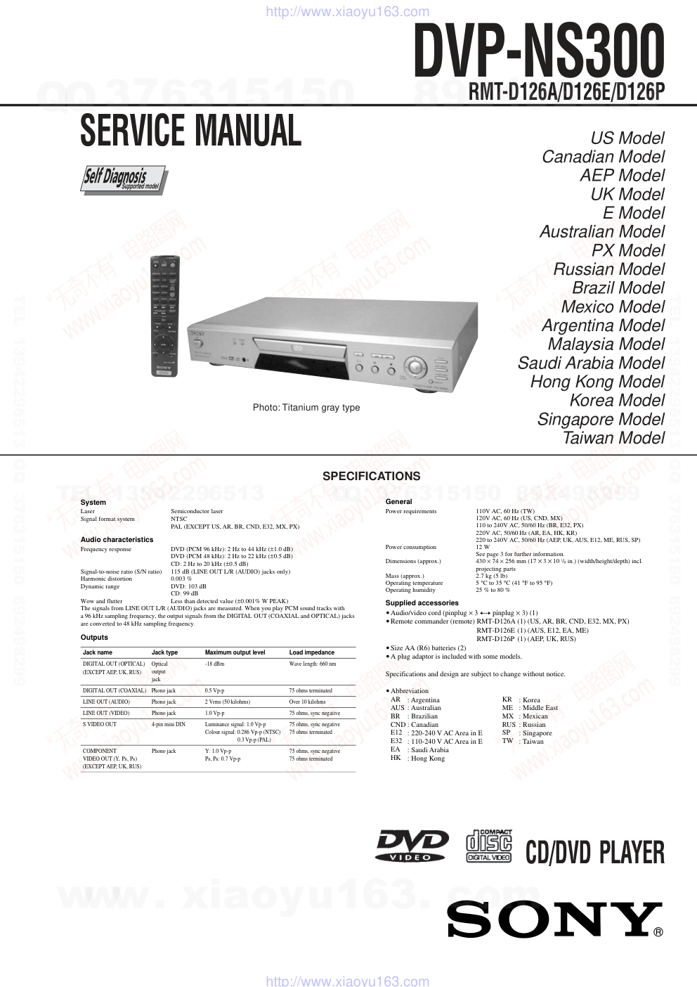
SERVICE MANUAL
US Model
Canadian Model
AEP Model
UK Model
E Model
Australian Model
PX Model
Russian Model
Brazil Model
Mexico Model
Argentina Model
Malaysia Model
Saudi Arabia Model
Hong Kong Model
Korea Model
Singapore Model
Taiwan Model
CD/DVD PLAYER
DVP-NS300
RMT-D126A/D126E/D126P
SPECIFICATIONS
• Audio/video cord (pinplug × 3 y pinplug × 3) (1)
• Remote commander (remote) RMT-D126A (1) (US, AR, BR, CND, E32, MX, PX)
RMT-D126E (1) (AUS, E12, EA, ME)
RMT-D126P (1) (AEP, UK, RUS)
• Size AA (R6) batteries (2)
• A
• Abbreviation
AR
AUS
BR
CND
E12
E32
EA
HK
plug a
: Argentina
: Australian
: Brazilian
: Canadian
: 220-240 V AC Area in E
: 110-240 V AC Area in E
: Saudi Arabia
: Hong Kong
KR
ME
MX
RUS
SP
TW
: Korea
: Middle East
: Mexican
: Russian
: Singapore
: Taiwan
daptor is included with some models.
System
Laser
Semiconductor laser
Signal format system
NT
PAL (EXCEPT US, AR, BR, CND, E32, MX, PX)
SC
Audio characteristics
Frequency response
DVD (PCM 96 kHz): 2 Hz to 44 kHz (±1.0 dB)
DVD (PCM 48 kHz): 2 Hz to 22 kHz (±0.5 dB)
CD: 2 Hz to 20 kHz (±0.5 dB)
Signal-to-noise ratio (S/N ratio)
115 dB (LINE OUT L/R (AUDIO) jacks only)
Harmonic distortion
0.003 %
Dynamic range
DVD: 103 dB
CD: 99 dB
Wow and flutter
Less than detected value (±0.001% W PEAK)
The signals from LINE OUT L/R (AUDIO) jacks are measured. When you play PCM sound tracks with
a 96 kHz sampling frequency, the output signals from the DIGITAL OUT (COAXIAL and OPTICAL) jacks
are converted to 48 kHz sampling frequency.
Outputs
General
Power requirements
120V AC, 60 Hz (US, CND, MX)
110V AC, 60 Hz (TW)
110 to 240V AC, 50/60 Hz (BR, E32, PX)
220V AC, 50/60 Hz (AR, EA, HK, KR)
220 to 240V AC, 50/60 Hz (AEP, UK, AUS, E12, ME, RUS, SP)
Power consumption
12 W
See page 3 for further information.
Dimensions (approx.)
430 × 74 × 256 mm (17 × 3 × 10 1/8 in.) (width/height/depth) incl.
projecting parts
Mass (approx.)
2.7 kg (5 lb)
Operating temperature
5 °C to 35 °C (41 °F to 95 °F)
Operating humidity
25 % to 80 %
Supplied accessories
Specifications and design are subject to change without notice.
Jack name
Jack type
Maximum output level
Load impedance
DI
(EXCEPT AEP, UK, RUS)
GITAL OUT (OPTICAL)
Optical
output
jack
-18 dBm
Wave length: 660 nm
DIGITAL OUT (COAXIAL)
Phono jack
0.5 Vp-p
75 ohms terminated
LINE OUT (AUDIO)
Phono jack
2 Vrms (50 kilohms)
Over 10 kilohms
LINE OUT (VIDEO)
Phono jack
1.0 Vp-p
75 ohms, sync negative
S VIDEO OUT
4-pin mini DIN
Luminance signal: 1.0 Vp-p
0.3 Vp-p (PAL)
75 ohms, sync negative
Colour signal: 0.286 Vp-p (NTSC)
75 ohms terminated
COMPONENT
(EXCEPT AEP, UK, RUS)
Phono jack
Y: 1.0 Vp-p
75 ohms, sync negative
VIDEO OUT (Y, PB, PR)
PB, PR: 0.7 Vp-p
75 ohms terminated
Photo: Titanium gray type
www. xiaoyu163. com
QQ 376315150
9
9
2
8
9
4
2
9
8
TEL 13942296513
9
9
2
8
9
4
2
9
8
0
5
1
5
1
3
6
7
3
Q
Q
TEL 13942296513 QQ 376315150 892498299
TEL 13942296513 QQ 376315150 892498299
http://www.xiaoyu163.com
– 2 –
WARNING!!
WHEN SERVICING, DO NOT APPROACH THE LASER
EXIT WITH THE EYE TOO CLOSELY. IN CASE IT IS
NECESSARY TO CONFIRM LASER BEAM EMISSION,
BE SURE TO OBSERVE FROM A DISTANCE OF
MORE THAN 25 cm FROM THE SURFACE OF THE
OBJECTIVE LENS ON THE OPTICAL PICK-UP BLOCK.
CAUTION
Use of controls or adjustments or performance of procedures
other than those specified herein may result in hazardous ra-
diation exposure.
ATTENTION AU COMPOSANT AYANT RAPPORT
À LA SÉCURITÉ!
LES COMPOSANTS IDENTIFIÉS PAR UNE MARQUE 0
SUR LES DIAGRAMMES SCHÉMATIQUES ET LA LISTE
DES PIÈCES SONT CRITIQUES POUR LA SÉCURITÉ
DE FONCTIONNEMENT. NE REMPLACER CES COM-
POSANTS QUE PAR DES PIÈCES SONY DONT LES
NUMÉROS SONT DONNÉS DANS CE MANUEL OU
DANS LES SUPPLÉMENTS PUBLIÉS PAR SONY.
SAFETY-RELATED COMPONENT WARNING!!
COMPONENTS IDENTIFIED BY MARK 0 OR DOTTED
LINE WITH MARK 0 ON THE SCHEMATIC DIAGRAMS
AND IN THE PARTS LIST ARE CRITICAL TO SAFE
OPERATION. REPLACE THESE COMPONENTS WITH
SONY PARTS WHOSE PART NUMBERS APPEAR AS
SHOWN IN THIS MANUAL OR IN SUPPLEMENTS PUB-
LISHED BY SONY.
CAUTION:
The use of optical instrument with this product will increase eye
hazard.
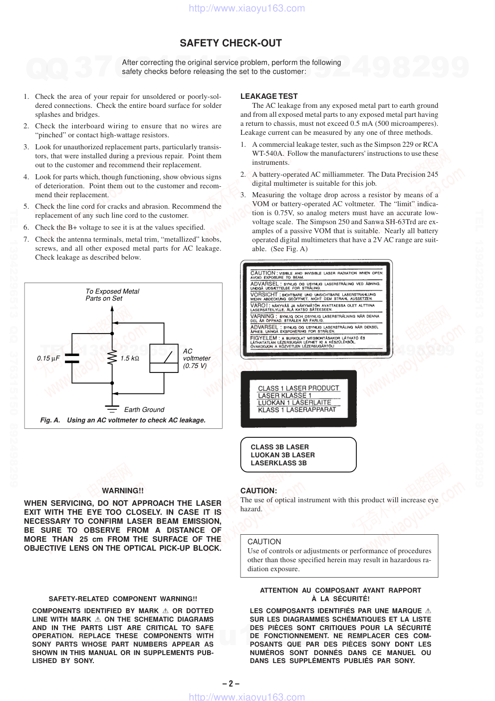
Fig. A.
Using an AC voltmeter to check AC leakage.
1.5 kΩ
0.15 µF
AC
voltmeter
(0.75 V)
To Exposed Metal
Parts on Set
Earth Ground
LEAKAGE TEST
The AC leakage from any exposed metal part to earth ground
and from all exposed metal parts to any exposed metal part having
a return to chassis, must not exceed 0.5 mA (500 microamperes).
Leakage current can be measured by any one of three methods.
1.
A commercial leakage tester, such as the Simpson 229 or RCA
WT-540A. Follow the manufacturers' instructions to use these
instruments.
2.
A battery-operated AC milliammeter. The Data Precision 245
digital multimeter is suitable for this job.
3.
Measuring the voltage drop across a resistor by means of a
VOM or battery-operated AC voltmeter. The “limit” indica-
tion is 0.75V, so analog meters must have an accurate low-
voltage scale. The Simpson 250 and Sanwa SH-63Trd are ex-
amples of a passive VOM that is suitable. Nearly all battery
operated digital multimeters that have a 2V AC range are suit-
able. (See Fig. A)
1.
Check the area of your repair for unsoldered or poorly-sol-
dered connections. Check the entire board surface for solder
splashes and bridges.
2.
Check the interboard wiring to ensure that no wires are
“pinched” or contact high-wattage resistors.
3.
Look for unauthorized replacement parts, particularly transis-
tors, that were installed during a previous repair. Point them
out to the customer and recommend their replacement.
4.
Look for parts which, though functioning, show obvious signs
of deterioration. Point them out to the customer and recom-
mend their replacement.
5.
Check the line cord for cracks and abrasion. Recommend the
replacement of any such line cord to the customer.
6.
Check the B+ voltage to see it is at the values specified.
7.
Check the antenna terminals, metal trim, “metallized” knobs,
screws, and all other exposed metal parts for AC leakage.
Check leakage as described below.
SAFETY CHECK-OUT
After correcting the original service problem, perform the following
safety checks before releasing the set to the customer:
CLASS 3B LASER
LUOKAN 3B LASER
LASERKLASS 3B
www. xiaoyu163. com
QQ 376315150
9
9
2
8
9
4
2
9
8
TEL 13942296513
9
9
2
8
9
4
2
9
8
0
5
1
5
1
3
6
7
3
Q
Q
TEL 13942296513 QQ 376315150 892498299
TEL 13942296513 QQ 376315150 892498299
http://www.xiaoyu163.com
– 3 –
TABLE OF CONTENTS
Section
Title
Page
Section
Title
Page
Service Note ............................................................................ 4
1.
GENERAL
Getting Started .............................................................. 1-3
Hookups ........................................................................ 1-3
Playing Discs ................................................................. 1-6
Searching for a Scene................................................... 1-8
Viewing Information About the Disc .............................. 1-9
Sound Adjustments ....................................................... 1-10
Enjoying Movies ............................................................ 1-10
Using Various Additional Functions .............................. 1-11
Settings and Adjustments ............................................. 1-13
Additional Information ................................................... 1-14
2.
DISASSEMBLY
2-1.
Case Removal ............................................................... 2-1
2-2.
MB-98 Board Removal .................................................. 2-1
2-3.
ER-14 Board Removal (AEP, UK, RUS) ....................... 2-1
2-4.
Rear Panel Removal ..................................................... 2-1
2-5.
AV-56 Board Removal ................................................... 2-2
2-6.
Tray Cover Removal ...................................................... 2-2
2-7.
Front Panel Removal ..................................................... 2-2
2-8.
Power Block Removal ................................................... 2-2
2-9.
Mechanism Deck Removal............................................ 2-3
2-10. Tray Removal ................................................................. 2-3
2-11. Loading Motor (M001), MS-81 Board Removal ............ 2-3
2-12. Optical Pick-up Removal ............................................... 2-3
2-13. IF-80 Board Removal .................................................... 2-4
2-14. Internal Views ................................................................ 2-5
2-15. Circuit Boards Location ................................................. 2-6
3.
BLOCK DIAGRAMS
3-1.
Overall Block Diagram................................................... 3-1
3-2.
RF/Servo Block Diagram ............................................... 3-3
3-3.
Signal Processor Block Diagram .................................. 3-5
3-4.
System Control Block Diagram ..................................... 3-7
3-5.
Video Block Diagram ..................................................... 3-9
3-6.
Audio Block Diagram ..................................................... 3-11
3-7.
Interface Control Block Diagram ................................... 3-13
3-8.
Power 1 Block Diagram ................................................. 3-15
3-9.
Power 2 Block Diagram ................................................. 3-17
3-10. Power 3 Block Diagram ................................................. 3-19
4.
PRINTED WIRING BOARDS AND SCHEMATIC
DIAGRAMS
4-1.
Frame Schematic Diagram............................................ 4-3
4-2.
Printed Wiring Boards and Schematic Diagrams ......... 4-5
MS-81 (LOADING) Printed Wiring Board and
Schematic Diagram ....................................................... 4-5
MB-98 Printed Wiring Board ......................................... 4-7
MB-98 (RF AMP, SERVO) Schematic Diagram ............ 4-11
MB-98 (ARP, SERVO DSP) Schematic Diagram .......... 4-13
MB-98 (AV DECODER) Schematic Diagram ................ 4-15
MB-98 (BNR) Schematic Diagram ................................ 4-17
MB-98 (DRIVE) Schematic Diagram ............................ 4-19
MB-98 (SYSTEM CONTROL)
Schematic Diagram ....................................................... 4-21
MB-98 (CLOCK GENERATOR)
Schematic Diagram ....................................................... 4-23
MB-98 (AUDIO DSP, D/A CONVERTER)
Schematic Diagram ....................................................... 4-25
AV-56 Printed Wiring Board .......................................... 4-29
AV-56 (VIDEO BUFFER) Schematic Diagram .............. 4-31
AV-56 (AUDIO AMP) Schematic Diagram .................... 4-33
IF-80 Printed Wiring Board ........................................... 4-35
IF-80 (IF CON) Schematic Diagram ............................. 4-37
ER-14 Printed Wiring Board (AEP, UK, RUS) ............... 4-39
ER-14 (EURO AV) Schematic Diagram
(AEP, UK, RUS) ............................................................. 4-41
HS13S0E Printed Wiring Board (AEP, UK, AR, AUS,
E12, EA, HK, KR, ME, RUS, SP) .................................. 4-43
HS13S0E Schematic Diagram (AEP, UK, AR, AUS,
E12, EA, HK, KR, ME, RUS, SP) .................................. 4-45
HS13S0F Printed Wiring Board (BR, E32, PX) ............ 4-47
HS13S0F Schematic Diagram (BR, E32, PX) .............. 4-49
HS13S0U Printed Wiring Board (US, CND, MX, TW) .. 4-51
HS13S0U Schematic Diagram (US, CND, MX, TW) .... 4-53
TOP-244U Printed Wiring Board (US, CND, MX) ......... 4-55
TOP-244U Schematic Diagram (US, CND, MX) ........... 4-57
5.
IC PIN FUNCTION DESCRIPTION
5-1.
System Control Pin Function
(MB-98 Board IC103) .................................................... 5-1
6.
TEST MODE
6-1.
General Description ...................................................... 6-1
6-2.
Starting Test Mode ........................................................ 6-1
6-3.
Syscon Diagnosis .......................................................... 6-1
6-4.
Drive Auto Adjustment .................................................. 6-5
6-5.
Drive Manual Operation ................................................ 6-7
6-6.
Mecha Aging ................................................................. 6-10
6-7.
Emergency History ........................................................ 6-10
6-8.
Version Information ....................................................... 6-11
6-9.
Video Level Adjustment ................................................ 6-11
6-10. IF CON Self Diagnostic Function .................................. 6-11
6-11. Troubleshooting ............................................................. 6-18
7.
ELECTRICAL ADJUSTMENT
7-1.
Power Supply Check ..................................................... 7-1
1.
HS13S0E/HS13S0F/HS13S0U/TOP-244U Boards...... 7-1
7-2.
Adjustment of Video System ......................................... 7-2
1.
Video Level Adjustment ................................................ 7-2
2.
Checking S Video Output S-Y ....................................... 7-2
3.
Checking S Video Output S-C....................................... 7-2
4.
Checking Component Video Output Y .......................... 7-2
5.
Checking Component Video Output B-Y ...................... 7-3
6.
Checking Component Video Output R-Y ...................... 7-3
7.
Checking RGB Output R ............................................... 7-3
8.
Checking RGB Output G ............................................... 7-3
9.
Checking RGB Output B ............................................... 7-4
7-3.
Adjustment Related Parts Arrangement ....................... 7-6
8.
REPAIR PARTS LIST
8-1.
Exploded Views ............................................................. 8-1
8-1-1.
Case Assembly ........................................................ 8-1
8-1-2.
Chassis Assembly .................................................... 8-3
8-1-3.
Mechanism Deck Assembly ..................................... 8-5
8-2.
Electrical Parts List ....................................................... 8-6
•
Abbreviation
AR
: Argentina
AUS
: Australian
BR
: Brazilian
CND : Canadian
E12
: 220-240 V AC Area in E
E32
: 110-240 V AC Area in E
EA
: Saudi Arabia
HK
: Hong Kong
KR
: Korea
ME
: Middle East
MX
: Mexican
RUS : Russian
SP
: Singapore
TW
: Taiwan
www. xiaoyu163. com
QQ 376315150
9
9
2
8
9
4
2
9
8
TEL 13942296513
9
9
2
8
9
4
2
9
8
0
5
1
5
1
3
6
7
3
Q
Q
TEL 13942296513 QQ 376315150 892498299
TEL 13942296513 QQ 376315150 892498299
http://www.xiaoyu163.com
– 4 –
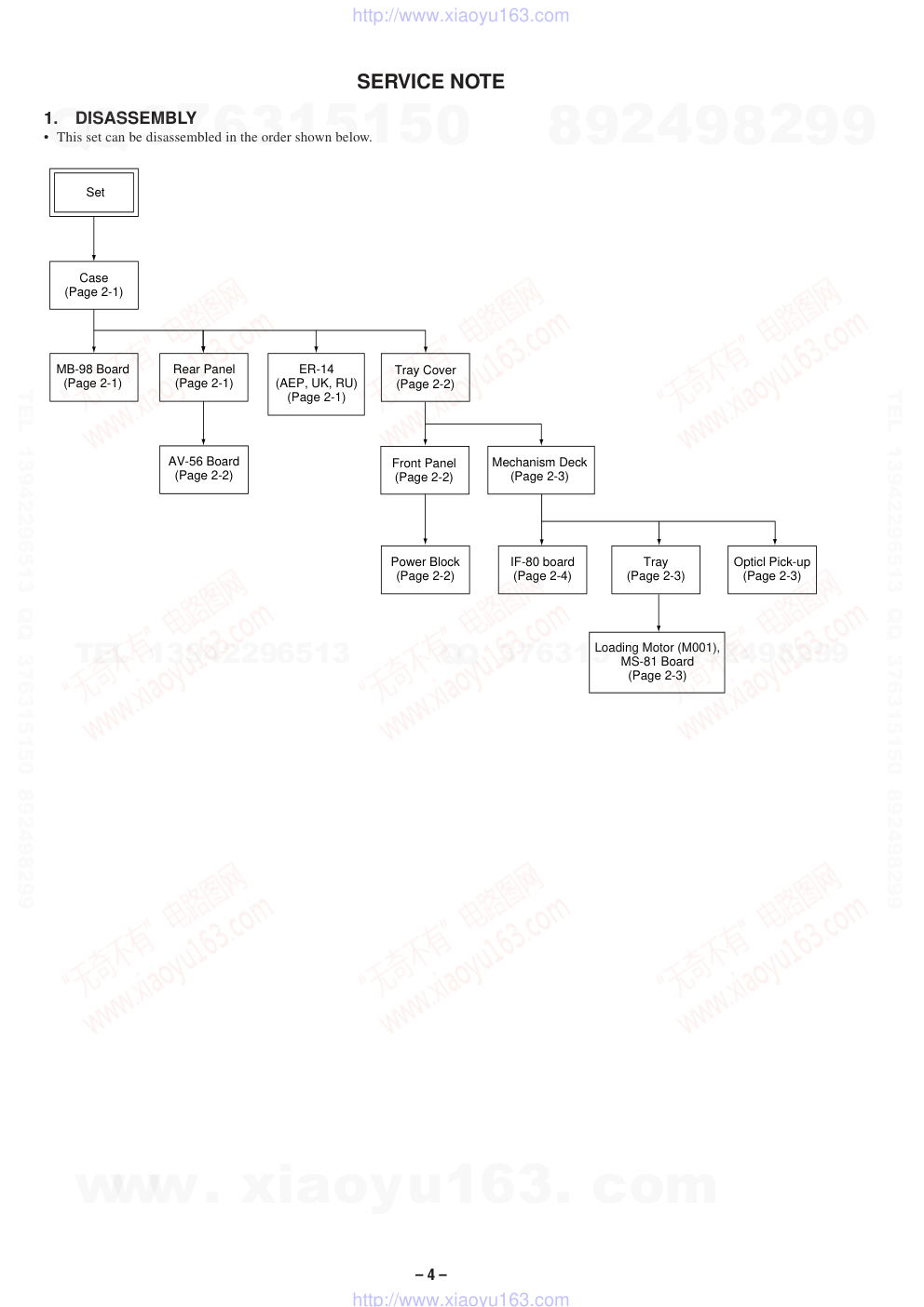
SERVICE NOTE
1.
DISASSEMBLY
• This set can be disassembled in the order shown below.
Set
Case
(Page 2-1)
Tray Cover
(Page 2-2)
Front Panel
(Page 2-2)
Tray
(Page 2-3)
Loading Motor (M001),
MS-81 Board
(Page 2-3)
Opticl Pick-up
(Page 2-3)
Power Block
(Page 2-2)
Mechanism Deck
(Page 2-3)
MB-98 Board
(Page 2-1)
ER-14
(AEP, UK, RU)
(Page 2-1)
IF-80 board
(Page 2-4)
AV-56 Board
(Page 2-2)
Rear Panel
(Page 2-1)
www. xiaoyu163. com
QQ 376315150
9
9
2
8
9
4
2
9
8
TEL 13942296513
9
9
2
8
9
4
2
9
8
0
5
1
5
1
3
6
7
3
Q
Q
TEL 13942296513 QQ 376315150 892498299
TEL 13942296513 QQ 376315150 892498299
http://www.xiaoyu163.com
– 5 –
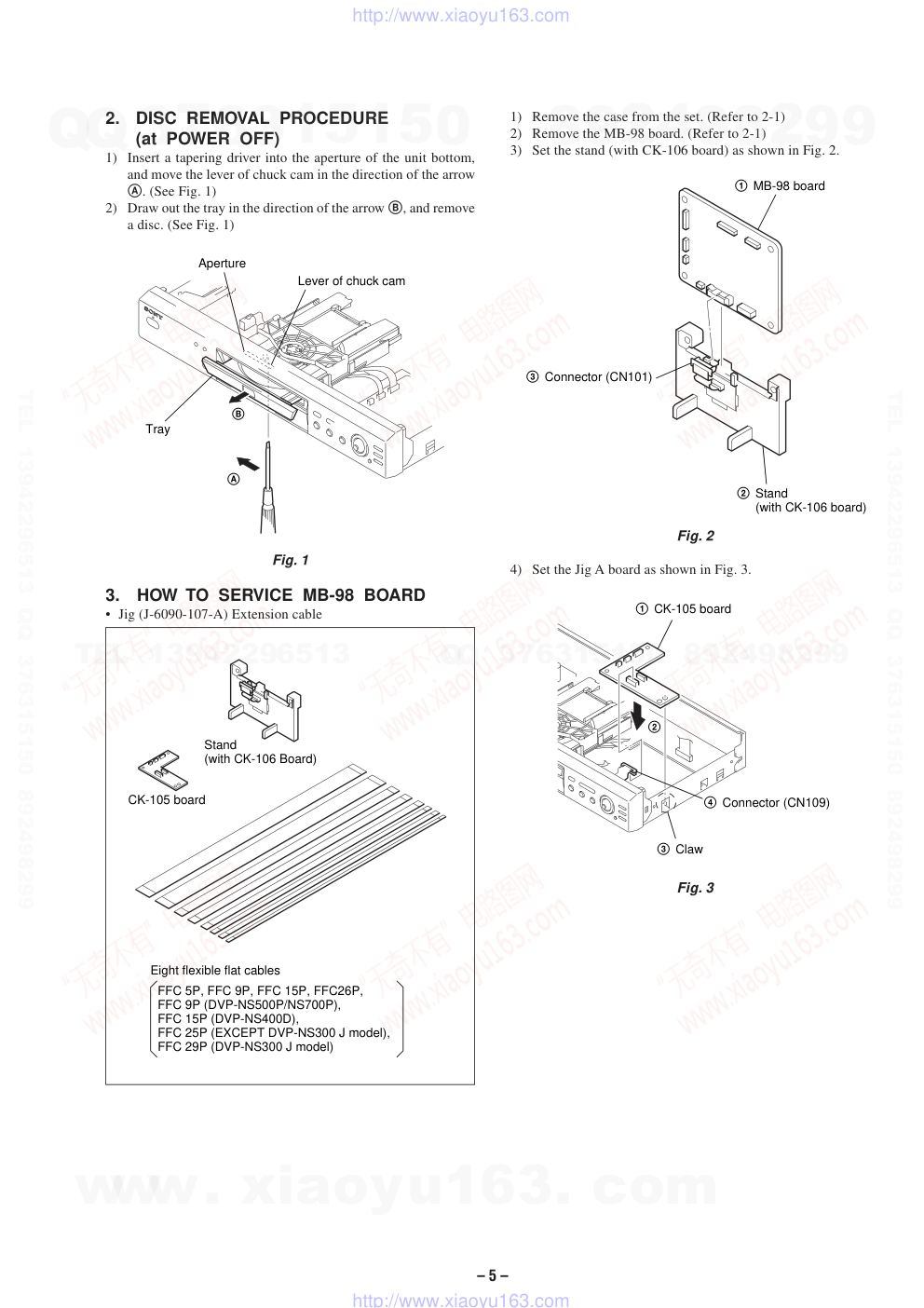
1) Remove the case from the set. (Refer to 2-1)
2) Remove the MB-98 board. (Refer to 2-1)
3) Set the stand (with CK-106 board) as shown in Fig. 2.
Fig. 2
4) Set the Jig A board as shown in Fig. 3.
Fig. 3
2.
DISC REMOVAL PROCEDURE
(at POWER OFF)
1) Insert a tapering driver into the aperture of the unit bottom,
and move the lever of chuck cam in the direction of the arrow
A. (See Fig. 1)
2) Draw out the tray in the direction of the arrow B, and remove
a disc. (See Fig. 1)
Fig. 1
3.
HOW TO SERVICE MB-98 BOARD
• Jig (J-6090-107-A) Extension cable
CK-105 board
Stand
(with CK-106 Board)
Eight flexible flat cables
FFC 5P, FFC 9P, FFC 15P, FFC26P,
FFC 9P (DVP-NS500P/NS700P),
FFC 15P (DVP-NS400D),
FFC 25P (EXCEPT DVP-NS300 J model),
FFC 29P (DVP-NS300 J model)
1 MB-98 board
2 Stand
(with CK-106 board)
3 Connector (CN101)
Tray
Lever of chuck cam
Aperture
B
A
4 Connector (CN109)
1 CK-105 board
3 Claw
2
www. xiaoyu163. com
QQ 376315150
9
9
2
8
9
4
2
9
8
TEL 13942296513
9
9
2
8
9
4
2
9
8
0
5
1
5
1
3
6
7
3
Q
Q
TEL 13942296513 QQ 376315150 892498299
TEL 13942296513 QQ 376315150 892498299
http://www.xiaoyu163.com
– 6 –
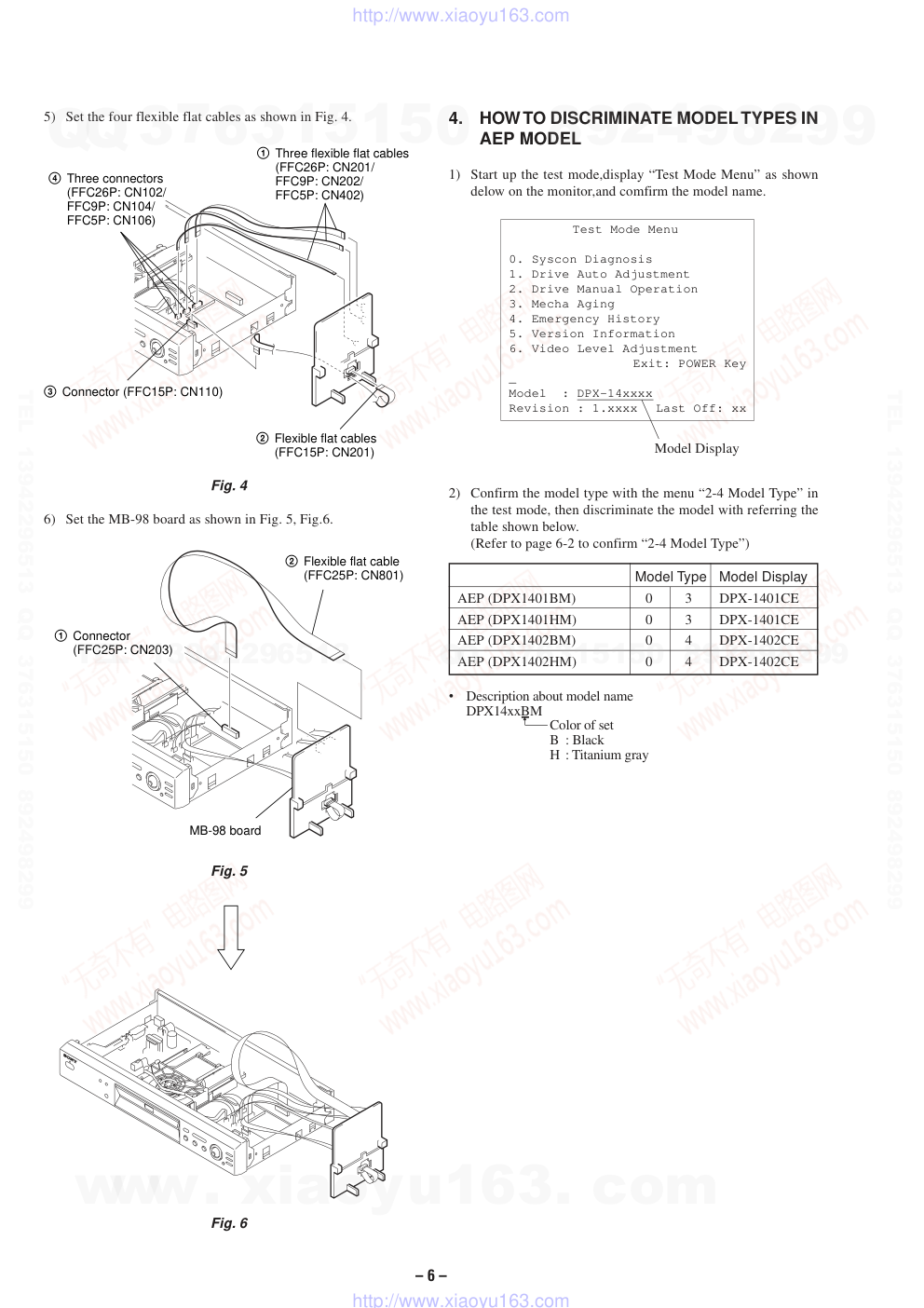
5) Set the four flexible flat cables as shown in Fig. 4.
Fig. 4
6) Set the MB-98 board as shown in Fig. 5, Fig.6.
Fig. 5
Fig. 6
3 Connector (FFC15P: CN110)
2 Flexible flat cables
(FFC15P: CN201)
4 Three connectors
(FFC26P: CN102/
FFC9P: CN104/
FFC5P: CN106)
1 Three flexible flat cables
(FFC26P: CN201/
FFC9P: CN202/
FFC5P: CN402)
1 Connector
(FFC25P: CN203)
2 Flexible flat cable
(FFC25P: CN801)
MB-98 board
4.
HOW TO DISCRIMINATE MODEL TYPES IN
AEP MODEL
1) Start up the test mode,display “Test Mode Menu” as shown
delow on the monitor,and comfirm the model name.
2) Confirm the model type with the menu “2-4 Model Type” in
the test mode, then discriminate the model with referring the
table shown below.
(Refer to page 6-2 to confirm “2-4 Model Type”)
Model Type
Model Display
AEP (DPX1401BM)
0
3
DPX-1401CE
AEP (DPX1401HM)
0
3
DPX-1401CE
AEP (DPX1402BM)
0
4
DPX-1402CE
AEP (DPX1402HM)
0
4
DPX-1402CE
•
Description about model name
DPX14xxBM
Color of set
B : Black
H : Titanium gray
Model Display
Test Mode Menu
0. Syscon Diagnosis
1. Drive Auto Adjustment
2. Drive Manual Operation
3. Mecha Aging
4. Emergency History
5. Version Information
6. Video Level Adjustment
Exit: POWER Key
_
Model : DPX-14xxxx
Revision : 1.xxxx
Last Off: xx
www. xiaoyu163. com
QQ 376315150
9
9
2
8
9
4
2
9
8
TEL 13942296513
9
9
2
8
9
4
2
9
8
0
5
1
5
1
3
6
7
3
Q
Q
TEL 13942296513 QQ 376315150 892498299
TEL 13942296513 QQ 376315150 892498299
http://www.xiaoyu163.com
– 7 –
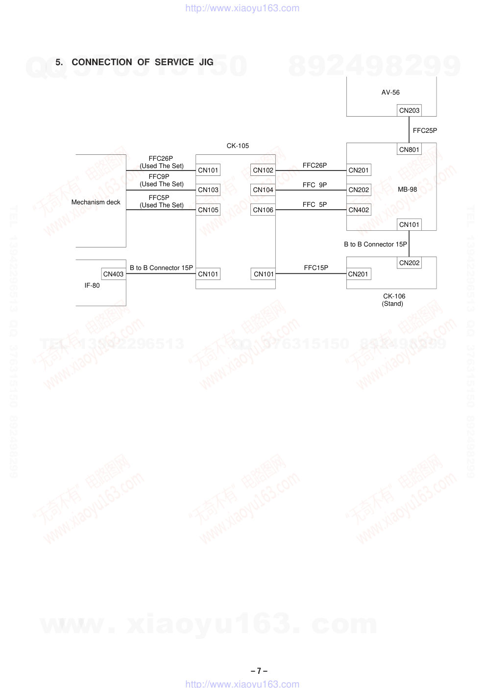
5.
CONNECTION OF SERVICE JIG
CK-105
Mechanism deck
IF-80
MB-98
AV-56
CK-106
(Stand)
B to B Connector 15P
B to B Connector 15P
FFC26P
(Used The Set)
FFC9P
(Used The Set)
FFC5P
(Used The Set)
FFC26P
FFC 9P
FFC 5P
FFC15P
FFC25P
CN101
CN102
CN103
CN104
CN105
CN106
CN201
CN202
CN402
CN101
CN403
CN101
CN201
CN202
CN101
CN801
CN203
www. xiaoyu163. com
QQ 376315150
9
9
2
8
9
4
2
9
8
TEL 13942296513
9
9
2
8
9
4
2
9
8
0
5
1
5
1
3
6
7
3
Q
Q
TEL 13942296513 QQ 376315150 892498299
TEL 13942296513 QQ 376315150 892498299
http://www.xiaoyu163.com
1-1
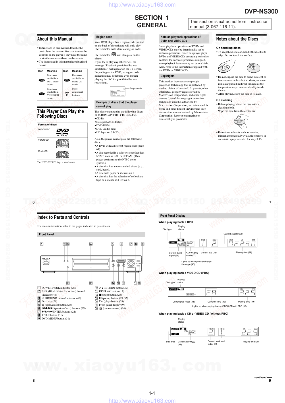
SECTION 1
GENERAL
This section is extracted from instruction
manual (3-067-116-11).
DVP-NS300
6
About this Manual
• Instructions in this manual describe the
controls on the remote. You can also use the
controls on the player if they have the same
or similar names as those on the remote.
• The icons used in this manual are described
below:
This Player Can Play the
Following Discs
The “DVD VIDEO” logo is a trademark.
Your DVD player has a region code printed
on the back of the unit and will only play
DVDs labeled with identical region codes.
DVDs labeled
will also play on this
player.
If you try to play any other DVD, the
message “Playback prohibited by area
limitations.” will appear on the TV screen.
Depending on the DVD, no region code
indication may be labeled even though
playing the DVD is prohibited by area
restrictions.
The player cannot play the following discs:
• CD-ROMs (PHOTO CDs included)
• CD-Rs
• Data part of CD-Extras
• DVD-ROMs
• DVD Audio discs
• HD layer on SACDs
Also, the player cannot play the following
discs:
• A DVD with a different region code (page
64).
• A disc recorded in a color system other than
NTSC, such as PAL or SECAM. (This
player conforms to the NTSC color
system.)
• A disc that has a non-standard shape (e.g.,
card, heart).
• A disc with paper or stickers on it.
• A disc that has the adhesive of cellophane
tape or a sticker still left on it.
Icon
Meaning
Icon
Meaning
Functions
available in
DVD video
mode
Functions
available in
music CD
mode
Functions
available in
VIDEO CD
mode
z
More
convenient
features
Format of discs
DVD VIDEO
VIDEO CD
Music CD
Region code
Example of discs that the player
cannot play
ALL
MODEL NO.
DVP–XXXX
CD/DVD PLAYER
AC 00V 00Hz
00W
NO.
SONY CORPORATION
MADE IN JAPAN
0-000-000-00
X
Region code
7
Some playback operations of DVDs and
VIDEO CDs may be intentionally set by
software producers. Since this player plays
DVDs and VIDEO CDs according to the disc
contents the software producers designed,
some playback features may not be available.
Also, refer to the instructions supplied with
the DVDs or VIDEO CDs.
This product incorporates copyright
protection technology that is protected by
method claims of certain U.S. patents, other
intellectual property rights owned by
Macrovision Corporation, and other rights
owners. Use of this copyright protection
technology must be authorized by
Macrovision Corporation, and is intended for
home and other limited viewing uses only
unless otherwise authorized by Macrovision
Corporation. Reverse engineering or
disassembly is prohibited.
Notes about the Discs
On handling discs
• To keep the disc clean, handle the disc by its
edge. Do not touch the surface.
• Do not expose the disc to direct sunlight or
heat sources such as hot air ducts, or leave
it in a car parked in direct sunlight as the
temperature may rise considerably inside
the car.
• After playing, store the disc in its case.
On cleaning
• Before playing, clean the disc with a
cleaning cloth.
Wipe the disc from the center out.
• Do not use solvents such as benzine,
thinner, commercially available cleaners, or
anti-static spray intended for vinyl LPs.
Note on playback operations of
DVDs and VIDEO CDs
Copyrights
8
Index to Parts and Controls
For more information, refer to the pages indicated in parentheses.
1 POWER switch/indicator (28)
2 BNR (Block Noise Reduction) button/
indicator (46)
3 SURROUND button/indicator (43)
4 Disc tray (28)
5 A (open/close) button (28)
6 ./> (previous/next) buttons (29)
7 C/X/x/c/ENTER buttons (24)
8 TITLE button (31)
9 DVD MENU button (31)
q; O RETURN button (32)
qa DISPLAY button (12)
qs x (stop) button (28)
qd X (pause) button (29, 52)
qf H (play) button (28)
qg Front panel display (9)
qh
(remote sensor) (14)
Front Panel
9
When playing back a DVD
When playing back a VIDEO CD (PBC)
When playing back a CD or VIDEO CD (without PBC)
Front Panel Display
DVD
PGM SHUFFLE
TITLE
CHAP
HOUR
MIN
SEC
DTS ANGLE REPEAT1
A-B
Digital
Playing time (39)
Disc type
Playing
status
Current chapter (39)
Current audio
signal (59)
Lights up when you can change
the angle (45)
Current play
mode (33)
Current title (39)
VIDEO CD
CD
PBC
MIN
SEC
A-B
Playing
status
Current play mode (33)
Disc type
Current scene (39)
Playing time (39)
Lights up when playing back a VIDEO CD with PBC (32)
VIDEO CD
CD
PGM SHUFFLE
TRACK
INDEX
MIN
SEC
REPEAT1
A-B
Playing time (39)
Disc type
Playing
status
Current track and
index (39)
Current play mode
(33)
continued
www. xiaoyu163. com
QQ 376315150
9
9
2
8
9
4
2
9
8
TEL 13942296513
9
9
2
8
9
4
2
9
8
0
5
1
5
1
3
6
7
3
Q
Q
TEL 13942296513 QQ 376315150 892498299
TEL 13942296513 QQ 376315150 892498299
http://www.xiaoyu163.com
1-2
10
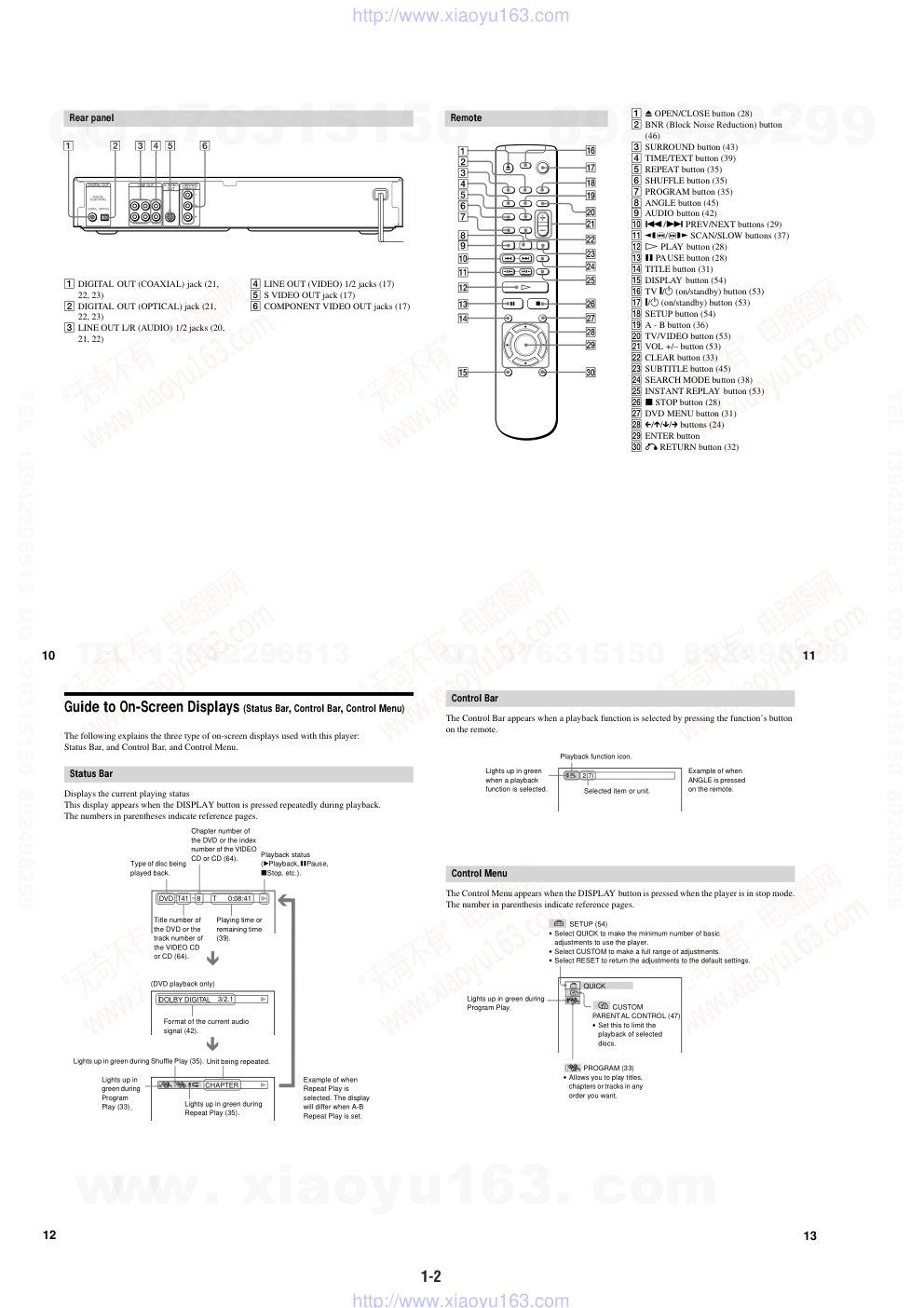
1 DIGITAL OUT (COAXIAL) jack (21,
22, 23)
2 DIGITAL OUT (OPTICAL) jack (21,
22, 23)
3 LINE OUT L/R (AUDIO) 1/2 jacks (20,
21, 22)
4 LINE OUT (VIDEO) 1/2 jacks (17)
5 S VIDEO OUT jack (17)
6 COMPONENT VIDEO OUT jacks (17)
Rear panel
PCM/DTS/
DOLBY DIGITAL
S VIDEO
OUT
COMPONENT
VIDEO OUT
COAXIAL
OPTICAL
R-AUDIO 1-L
VIDEO 1
Y
PB
PR
R-AUDIO 2-L
VIDEO 2
DIGITAL OUT
LINE OUT
11
1 Z OPEN/CLOSE button (28)
2 BNR (Block Noise Reduction) button
(46)
3 SURROUND button (43)
4 TIME/TEXT button (39)
5 REPEAT button (35)
6 SHUFFLE button (35)
7 PROGRAM button (35)
8 ANGLE button (45)
9 AUDIO button (42)
q; ./> PREV/NEXT buttons (29)
qa
/
y SCAN/SLOW buttons (37)
qs H PLAY button (28)
qd X PAUSE button (28)
qf TITLE button (31)
qg DISPLAY button (54)
qh TV [/1 (on/standby) button (53)
qj ]/1 (on/standby) button (53)
qk SETUP button (54)
ql A - B button (36)
w; TV/VIDEO button (53)
wa VOL +/– button (53)
ws CLEAR button (33)
wd SUBTITLE button (45)
wf SEARCH MODE button (38)
wg INSTANT REPLAY button (53)
wh x STOP button (28)
wj DVD MENU button (31)
wk C/X/x/c buttons (24)
wl ENTER button
e; O RETURN button (32)
Remote
y
12
Guide to On-Screen Displays (Status Bar, Control Bar, Control Menu)
The following explains the three type of on-screen displays used with this player:
Status Bar, and Control Bar, and Control Menu.
Displays the current playing status
This display appears when the DISPLAY button is pressed repeatedly during playback.
The numbers in parentheses indicate reference pages.
Status Bar
DVD T41 – 8
T
0:08:41
3/2.1
DOLBY DIGITAL
CHAPTER
Type of disc being
played back.
Title number of
the DVD or the
track number of
the VIDEO CD
or CD (64).
Chapter number of
the DVD or the index
number of the VIDEO
CD or CD (64).
Playback status
(BPlayback, XPause,
xStop, etc.).
(DVD playback only)
Lights up in green during Shuffle Play (35).
Lights up in green during
Repeat Play (35).
Playing time or
remaining time
(39).
Unit being repeated.
Format of the current audio
signal (42).
Example of when
Repeat Play is
selected. The display
will differ when A-B
Repeat Play is set.
Lights up in
green during
Program
Play (33).
13
The Control Bar appears when a playback function is selected by pressing the function’s button
on the remote.
The Control Menu appears when the DISPLAY button is pressed when the player is in stop mode.
The number in parenthesis indicate reference pages.
Control Bar
2(7)
Playback function icon.
Selected item or unit.
Lights up in green
when a playback
function is selected.
Example of when
ANGLE is pressed
on the remote.
Control Menu
QUICK
CUSTOM
PARENTAL CONTROL (47)
• Set this to limit the
playback of selected
discs.
PROGRAM (33)
• Allows you to play titles,
chapters or tracks in any
order you want.
SETUP (54)
• Select QUICK to make the minimum number of basic
adjustments to use the player.
• Select CUSTOM to make a full range of adjustments.
• Select RESET to return the adjustments to the default settings.
Lights up in green during
Program Play.
www. xiaoyu163. com
QQ 376315150
9
9
2
8
9
4
2
9
8
TEL 13942296513
9
9
2
8
9
4
2
9
8
0
5
1
5
1
3
6
7
3
Q
Q
TEL 13942296513 QQ 376315150 892498299
TEL 13942296513 QQ 376315150 892498299
http://www.xiaoyu163.com
1-3
14
Getting Started
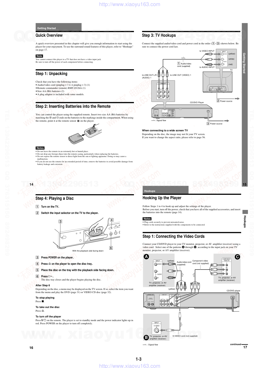
Quick Overview
A quick overview presented in this chapter will give you enough information to start using the
player for your enjoyment. To use the surround sound features of this player, refer to “Hookups”
on page 17.
Note
You cannot connect this player to a TV that does not have a video input jack.
Be sure to turn off the power of each component before connecting.
Step 1: Unpacking
Check that you have the following items:
• Audio/video cord (pinplug × 3 y pinplug × 3) (1)
• Remote commander (remote) RMT-D126A (1)
• Size AA (R6) batteries (2)
• A plug adaptor is included with some models.
Step 2: Inserting Batteries into the Remote
You can control the player using the supplied remote. Insert two size AA (R6) batteries by
matching the 3 and # ends on the batteries to the markings inside the compartment. When using
the remote, point it at the remote sensor
on the player.
Notes
• Do not leave the remote in an extremely hot or humid place.
• Do not drop any foreign object into the remote casing, particularly when replacing the batteries.
• Do not expose the remote sensor to direct light from the sun or lighting apparatus. Doing so may cause a
malfunction.
• If you do not use the remote for an extended period of time, remove the batteries to avoid possible damage from
battery leakage and corrosion
.
15
Getting Started
Step 3: TV Hookups
Connect the supplied audio/video cord and power cord in the order (1~3) shown below. Be
sure to connect the power cord last.
When connecting to a wide screen TV
Depending on the disc, the image may not fit your TV screen.
If you want to change the aspect ratio, please refer to page 56.
PCM/DTS/
DOLBY DIGITAL
S VIDEO
OUT
COMPONENT
VIDEO OUT
COAXIAL
OPTICAL
R-AUDIO 1-L
VIDEO 1
Y
PB
PR
R-AUDIO 2-L
VIDEO 2
DIGITAL OUT
LINE OUT
R-AUDIO 1-L
VIDEO 1
R-AUDIO 2-L
VIDEO 2
LINE OUT
VIDEO
AUDIO
INPUT
L
R
3 Power source
CD/DVD Player
TV
2 Power source
l: Signal flow
to VIDEO INPUT
to LINE OUT (VIDEO) 1
to LINE OUT L/R
(AUDIO) 1
to AUDIO INPUT
1 Audio/video
cord (supplied)
(yellow)
(white)
(red)
16
Step 4: Playing a Disc
1 Turn on the TV.
2 Switch the input selector on the TV to the player.
3 Press POWER on the player.
4 Press A on the player to open the disc tray.
5 Place the disc on the tray with the playback side facing down.
6 Press H.
The disc tray closes and the player begins playing the disc.
After Step 6
Depending on the disc, a menu may be displayed on the TV screen. If so, select the item you want
from the menu and play the DVD (page 31) or VIDEO CD disc (page 32).
To stop playing
Press x.
To take out the disc
Press A.
To turn off the player
Press ^/1 on the remote. The player is set to standby mode and the power indicator lights up in
red. Press POWER on the player to turn off completely.
With the playback side facing down
Hookups
17
Hookups
Hooking Up the Player
Follow Steps 1 to 4 to hook up and adjust the settings of the player.
Before you start, turn off the power, check that you have all of the supplied accessories, and insert
the batteries into the remote (page 14).
Notes
• Plug cords securely to prevent unwanted noise.
• Refer to the instructions supplied with the components to be connected.
Step 1: Connecting the Video Cords
Connect your CD/DVD player to your TV monitor, projector, or AV amplifier (receiver) using a
video cord. Select one of the patterns A through C, according to the input jack on your TV
monitor, projector, or AV amplifier (receiver).
INPUT
S VIDEO
B
PCM/DTS/
DOLBY DIGITAL
S VIDEO
OUT
COMPONENT
VIDEO OUT
COAXIAL
OPTICAL
R-AUDIO 1-L
VIDEO 1
Y
PB
PR
R-AUDIO 2-L
VIDEO 2
DIGITAL OUT
LINE OUT
PR
PB
Y
COMPONENT
VIDEO IN
C
AUDIO
VIDEO
INPUT
L
R
A
CD/DVD player
l : Signal flow
Component video
cord (not supplied)
Audio/video cord
(supplied)
S VIDEO cord (not supplied)
(yellow)
(yellow)
TV, projector, or AV
amplifier (receiver)
TV, projector, or AV
amplifier (receiver)
TV, projector, or AV
amplifier (receiver)
continued
www. xiaoyu163. com
QQ 376315150
9
9
2
8
9
4
2
9
8
TEL 13942296513
9
9
2
8
9
4
2
9
8
0
5
1
5
1
3
6
7
3
Q
Q
TEL 13942296513 QQ 376315150 892498299
TEL 13942296513 QQ 376315150 892498299
http://www.xiaoyu163.com
1-4
18
Connect the yellow plug of the audio/video cord (supplied) to the yellow (video) jacks. You will
enjoy standard quality images.
Use the red and white plugs to connect to the audio input jacks (page 19).
Connect the S VIDEO cord (not supplied). You will enjoy high quality images.
Connect the component via the COMPONENT VIDEO OUT jacks using a component video cord
(not supplied) or three video cords (not supplied) of the same kind and length. You will enjoy
accurate color reproduction and high quality images.
Note
Do not connect your player to a VCR. You may not receive a clear image on the TV screen if you pass the player
signals via the VCR.
A If you are connecting to a video input jack
B If you are connecting to an S VIDEO input jack
C If you are connecting to a monitor, projector, or AV amplifier (receiver) having
component video input jacks (Y, PB, PR)
Yellow (Video)
White (L)
Red (R)
Ye llow (Video)
White (L)
Red (R)
VCR
CD/DVD player
TV
Connect directly
Hookups
19
Step 2: Connecting the Audio Cords
Refer to the chart below to select the connection that best suits your system. The surround effects
you will enjoy depend on the connections and components you use.
Select one of the following connections,
through
.
* Manufactured under license from Dolby Laboratories. “Dolby,” “Pro Logic,” and the double-D symbol are
trademarks of Dolby Laboratories. Confidential unpublished works. © 1992-1997 Dolby Laboratories. All rights
reserved.
** “DTS” is a registered trademark of Digital Theater Systems, Inc.
Select a connection
Connection
Components to be connected
(page 20)
• TV (stereo)
(page 21)
• Stereo amplifier (receiver)
(having L and R audio input jacks only, or having a digital input jack)
• 2 speakers
(front L and R)
(page 21)
• MD deck/DAT deck
(page 22)
• AV amplifier (receiver) with a Dolby* Surround (Pro Logic) decoder
(having L and R audio input jacks only, or having a digital input jack)
• 3 speakers
(front L and R, and rear (monaural))
• 6 speakers
(front L and R, center, rear L and R, and subwoofer)
(page 23)
• AV amplifier (receiver) having a Dolby Digital or DTS** decoder and a digital
input jack
• 6 speakers
(front L and R, rear L and R, center, and subwoofer)
A
D
A
B
B
C
D
continued
20
This connection will use your TV speakers for sound.
xRecommended surround sound effects for this connection
•TVS DYNAMIC (page 43)
•TVS WIDE (page 43)
The yellow plug is used for video signals (page 17).
Connecting to your TV
A
PCM/DTS/
DOLBY DIGITAL
S VIDEO
OUT
COMPONENT
VIDEO OUT
COAXIAL
OPTICAL
R-AUDIO 1-L
VIDEO 1
Y
PB
PR
R-AUDIO 2-L
VIDEO 2
DIGITAL OUT
LINE OUT
R-AUDIO 1-L
VIDEO 1
R-AUDIO 2-L
VIDEO 2
LINE OUT
A
TV
l : Signal flow
CD/DVD player
Audio/video cord
(supplied)
(white)
(red)
(yellow)
(white)
(red)
(yellow)
to audio input
Hookups
21
This connection will use your 2 front speakers connected to your stereo amplifier (receiver) for
sound. If the stereo amplifier (receiver) has audio input jacks L and R only, use
. If the
amplifier (receiver) has a digital input jack, use
. When connecting to an MD deck or a DAT
deck, use
. In this case, you can also connect the player directly to the MD deck or DAT
deck without using your stereo amplifier (receiver).
xRecommended surround sound effects for the
connection only
•TVS STANDARD (page 43)
z In connection
, you can use the supplied audio/video cord instead of using a separate audio cord.
z To realize better surround sound effects, make sure that your listening position is in between your speakers.
Note
If you select one of the TVS effects while playing a disc, no sound will come from your speakers with the
connection.
Connecting to a stereo amplifier (receiver) and 2 speakers/Connecting to
an MD deck or DAT deck
B
B-1
B-2
B-2
B-1
B-1
B-2
PCM/DTS/
DOLBY DIGITAL
S VIDEO
OUT
COMPONENT
VIDEO OUT
COAXIAL
OPTICAL
R-AUDIO 1-L
VIDEO 1
Y
PB
PR
R-AUDIO 2-L
VIDEO 2
DIGITAL OUT
LINE OUT
PCM/DTS/
DOLBY DIGITAL
COAXIAL
OPTICAL
DIGITAL OUT
B-2
B-1
VIDEO 1
R-AUDIO 2-L
VIDEO 2
LINE OUT
R-AUDIO 1-L
l: Signal flow
CD/DVD player
or
Stereo amplifier (receiver)
MD deck/DAT deck
Front
(L)
Front
(R)
[Speakers]
(white)
(red)
(white)
(red)
Coaxial digital
cord (not supplied)
Stereo audio cord
(not supplied)
Optical digital cord
(not supplied)
Remove jack cap
before connecting
or
to coaxial or optical digital input
to audio input
continued
www. xiaoyu163. com
QQ 376315150
9
9
2
8
9
4
2
9
8
TEL 13942296513
9
9
2
8
9
4
2
9
8
0
5
1
5
1
3
6
7
3
Q
Q
TEL 13942296513 QQ 376315150 892498299
TEL 13942296513 QQ 376315150 892498299
http://www.xiaoyu163.com
1-5
22
This connection will allow you to enjoy the surround effects of the Pro Logic decoder on your
amplifier (receiver). If you have an AV amplifier (receiver) equipped with a Dolby Digital, or
DTS decoder, refer to page 23.
You can enjoy the Dolby Surround effects only when playing Dolby Surround audio or multi-
channel audio (Dolby Digital) discs.
Pro Logic uses a minimum of 3 speakers (front L and R, and rear (monaural)). The surround
effects are enhanced if 6 speakers (front L and R, center, rear L and R, and subwoofer) are used.
If your amplifier (receiver) has R and L audio input jacks only, use
. If your amplifier
(receiver) has a digital input jack, use
.
xRecommended surround sound effects using this connection with your amplifier (receiver)
•Dolby Surround (Pro Logic) (page 64)
z For correct speaker setting location, please refer to the operating instructions of the amplifier (receiver).
∗When connecting 6 speakers, replace the monaural rear speaker with a center speaker, 2 rear speakers and a
subwoofer.
Connecting to a Dolby Surround (Pro Logic) decoder amplifier (receiver) and
3 to 6 speakers
C
C-1
C-2
PCM/DTS/
DOLBY DIGITAL
S VIDEO
OUT
COMPONENT
VIDEO OUT
COAXIAL
OPTICAL
R-AUDIO 1-L
VIDEO 1
Y
PB
PR
R-AUDIO 2-L
VIDEO 2
DIGITAL OUT
LINE OUT
PCM/DTS/
DOLBY DIGITAL
COAXIAL
OPTICAL
DIGITAL OUT
C-2
VIDEO 1
R-AUDIO 2-L
VIDEO 2
LINE OUT
R-AUDIO 1-L
C-1
CD/DVD player
Front
(R)
Front
(L)
Rear
(R)
Subwoofer
l: Signal flow
Dolby Surround amplifier (receiver)
center
Rear*
(mono)
[Speakers]
or
Coaxial digital cord
(not supplied)
Stereo audio cord
(not supplied)
Optical digital cord
(not supplied)
Remove jack cap
before connecting
or
to coaxial or optical digital input
to audio input
(red)
(white)
Rear
(L)
[Speakers]
Hookups
23
This connection will allow you to use the Dolby Digital, or DTS decoder function of your AV
amplifier (receiver). You are not able to enjoy the TVS sound effects of the player.
xRecommended surround sound effects using this connection with your amplifier (receiver)
•Dolby Digital (5.1ch) (page 64)
•DTS (5.1ch) (page 64)
z To enhance the surround sound effects, refer to the operating instructions of the amplifier (receiver) for correct
speaker setting location.
Note
After you have completed the connection, be sure to set “DOLBY DIGITAL” to “DOLBY DIGITAL”(page 24).
If your AV amplifier (receiver) has a DTS decoder, set “DTS” to “ON” (page 28). Otherwise, no sound or a loud
noise will come from the speakers.
Connecting to an AV amplifier (receiver) with a digital input jack having a
Dolby Digital, or DTS decoder, and 6 speakers
D
PCM/DTS/
DOLBY DIGITAL
S VIDEO
OUT
COMPONENT
VIDEO OUT
COAXIAL OPTICAL
R-AUDIO 1-L
VIDEO 1
Y
PB
PR
R-AUDIO 2-L
VIDEO 2
DIGITAL OUT
LINE OUT
OPTICAL
PCM/DTS/
DOLBY DIGITAL
DIGITAL OUT
COAXIAL
D
Front
(R)
Rear
(R)
AV amplifier (receiver) with a decoder
Subwoofer
Center
[Speakers]
[Speakers]
CD/DVD player
or
: Signal flow
Coaxial digital cord
(not supplied)
to optical digital input
to coaxial digital input
Optical digital cord
(not supplied)
Remove jack cap
before connecting
Front (L)
Rear
(L)
24
Step 3: Connecting the Power Cord
Plug the player and TV power cords into an AC outlet.
Do not connect the power cord of your player to the “switched” power socket of an amplifier
(receiver). Otherwise, when you turn off the power of your amplifier (receiver), the settings for
the player may be lost.
Step 4: Quick Setup
Follow the steps below to make the minimum number of basic adjustments to use the player.
To skip an adjustment, press >. To return to the previous adjustment, press ..
A Turn on the TV.
B Switch the input selector on the TV to the player.
C Press POWER on the player and press [/1 on the remote.
“Press [ENTER] to run QUICK SETUP” appears at the bottom of the screen. If this
message does not appear, select “QUICK” under SETUP in the Control Menu (page 13) to
run Quick Setup.
D Press ENTER without inserting a disc.
The Setup Display for selecting the language used in the on-screen display appears.
./> X/x
POWER
./>
X/x
I/1
[/1
ENTER
ENTER
LANGUAGE SETUP
OSD:
DVD MENU:
AUDIO:
SUBTITLE:
FRENCH
ENGLISH
ENGLISH
SPANISH
PORTUGUESE
Hookups
25
E Press X/x to select a language.
The player uses the language selected here to display the DVD menu and subtitles as well.
F Press ENTER.
The Setup Display for selecting the aspect ratio of the TV to be connected appears.
G Press X/x to select the item.
H Press ENTER.
The Setup Display for selecting the type of jack used to connect your amplifier (receiver)
appears.
I Press X/x to select the item, then press ENTER.
• When “NO” or “LINE OUTPUT L/R (AUDIO)” is selected, Quick Setup is finished and
connections are complete.
• When “DIGITAL OUTPUT” is selected, the Setup Display for “DOLBY DIGITAL”
appears. Proceed to Step 0.
J Press X/x to select the item.
Choose the item that matches the audio connection you selected in page 21 to 23 (
through
).
TV type
You select
Page
4:3 standard TV
4:3 LETTER BOX or 4:3 PAN
SCAN
56
A wide-screen TV or 4:3 standard TV with
the wide-screen mode
16:9
56
SCREEN SETUP
TV TYPE:
SCREEN SAVER:
BACKGROUND:
4:3 PAN SCAN
4:3 LETTER BOX
16:9
4:3 LETTER BOX
YES
NO
Is this player connected to an amplifier
(receiver) ? Select the type of jack you
are using.
LINE OUTPUT L/R (AUDIO)
DIGITAL OUTPUT
B
AD
AUDIO SETUP
AUDIO ATT:
AUDIO DRC:
DIGITAL OUT:
DOLBY DIGITAL:
DTS:
OFF
STANDARD
ON
DOWNMIX:
DOLBY SURROUND
DOLBY DIGITAL
D-PCM
D-PCM
continued
www. xiaoyu163. com
QQ 376315150
9
9
2
8
9
4
2
9
8
TEL 13942296513
9
9
2
8
9
4
2
9
8
0
5
1
5
1
3
6
7
3
Q
Q
TEL 13942296513 QQ 376315150 892498299
TEL 13942296513 QQ 376315150 892498299
http://www.xiaoyu163.com
1-6
26
qa Press ENTER.
DTS is selected.
Press X/x to select the item.
Choose the item that matches the audio connection you selected in page 21 to 23 (
through
).
qd Press ENTER.
Quick Setup is finished. All connections and setup operations are complete.
Note
You can directly start Quick Setup only when you run it for the first time.
To run Quick Setup a second time, select “QUICK” under SETUP in the Control Menu (page 54).
To enjoy the surround sound effects of this player or your amplifier (receiver), the following
items must be set as described below for the audio connection you selected in page 21 to 23
(
through
). Each of these are the default settings and do not need to be adjusted when
you first connect the player. Refer to page 56 for using the Setup Display.
Audio Cord Connection Type
You select
Page
D-PCM
59
DOLBY DIGITAL (only if the
amplifier/receiver has a Dolby
Digital decoder)
59
Audio Cord Connection Type
You select
Page
OFF
59
ON (only if the amplifier/receiver
has a DTS decoder)
59
Enjoying the surround sound effects
B-2
C-2
D
AUDIO SETUP
AUDIO ATT:
AUDIO DRC:
DIGITAL OUT:
DOLBY DIGITAL:
DTS:
OFF
STANDARD
ON
DOWNMIX:
DOLBY SURROUND
D-PCM
OFF
OFF
ON
B
AD
B-2
C-2
AD
B
AD
Hookups
27
Audio Connection (page 19 to 23)
No additional settings are needed.
• If the sound distorts even when the volume is turned down, set “AUDIO ATT” to “ON” (page 58).
Item
You select
Page
DOWNMIX
DOLBY SURROUND
58
Item
You select
Page
DOWNMIX
DOLBY SURROUND
58
DIGITAL OUT
ON
59
A
B-1
C-1
B-2
C-2
D
28
Playing Discs
Playing Discs
Depending on the DVD or VIDEO CD, some
operations may be different or restricted.
Refer to the operating instructions supplied
with your disc.
1
Turn on your TV.
2
Switch the input selector on the TV
to the player.
When using an amplifier (receiver)
Turn on the amplifier (receiver) and
select the appropriate channel.
3
Press POWER on the player.
The player enters standby mode and the
power indicator lights up in red.
4
Press A on the player, and place a
disc on the disc tray.
The player automatically turns on and
the power indicator lights up in green.
5
Press H.
The disc tray closes, and the player
starts playback (continuous play).
Adjust the volume on the TV or the
amplifier (receiver).
After following Step 5
Depending on the disc, a menu may appear
on the TV screen. You can play the disc
interactively by following the instructions on
the menu. DVD (page 31), VIDEO CD (page
32).
To turn on the player
Press the POWER switch on the player. The
player enters standby mode and the power
indicator lights up in red. Press [/1 on the
remote. The player turns on and the power
indicator lights up in green. In standby mode,
the player also turns on by pressing A on the
player or by pressing H.
To turn off the player
Press [/1 on the remote. The player enters
standby mode and the power indicator lights
up in red. To turn off the player completely,
press POWER on the player. While playing
a disc, do no turn off the player by pressing
POWER. Doing so may cancel the menu
settings. When you turn off the player, first
press x to stop playback and then press [/1
on the remote
POWER
A
H
Power indicator
[/1
H
x
AUDIO
x
With the playback side facing down
Playing Discs
29
Notes on playing DTS sound tracks on
a CD
• When playing DTS-encoded CDs,
excessive noise will be heard from the
analog stereo jacks. To avoid possible
damage to the audio system, the consumer
should take proper precautions when the
analog stereo jacks of the player are
connected to an amplification system. To
enjoy DTS Digital Surround™ playback, an
external 5.1-channel decoder system must
be connected to the digital jacks of the
player.
• Set the sound to “STEREO” using the
AUDIO button when you play DTS sound
tracks on a CD (page 42).
• Do not play DTS sound tracks without first
connecting the player to an audio
component having a built-in DTS decoder.
The player outputs the DTS signal via the
DIGITAL OUT (OPTICAL and
COAXIAL) jacks even if “DTS” in
“AUDIO SETUP” is set to “OFF” in the
Setup Display (page 60), and may affect
your ears or cause your speakers to be
damaged.
Notes on playing DVDs with a DTS
sound track
• DTS audio signals are output only through
the DIGITAL OUT (OPTICAL and
COAXIAL) jacks.
• If you connect the player to audio
equipment without a DTS decoder, do not
set “DTS” to “ON” in “AUDIO SETUP”
(page 59). A loud noise may come out from
the speakers, affecting your ears or causing
the speakers to be damaged.
• When you play a DVD with DTS sound
tracks, set “DTS” to “ON” in “AUDIO
SETUP” (page 59).
z The Instant Replay function is useful when you
want to review a scene or dialog that you missed.
Note
You may not be able to use the Instant Replay function
with some scenes.
Additional operations
To
Operation
Stop
Press x
Pause
Press X
Resume play after
pause
Press X or H
Go to the next chapter,
track or scene in
continuous play mode
Press >
Go back to the
preceding chapter,
track or scene in
continuous play mode
Press .
Stop play and remove
the disc
Press Z
Replay a previous
scene (DVD only)
Press INSTANT
REPLAY
. />
X
Z
x
INSTANT
REPLAY
H
www. xiaoyu163. com
QQ 376315150
9
9
2
8
9
4
2
9
8
TEL 13942296513
9
9
2
8
9
4
2
9
8
0
5
1
5
1
3
6
7
3
Q
Q
TEL 13942296513 QQ 376315150 892498299
TEL 13942296513 QQ 376315150 892498299
http://www.xiaoyu163.com
1-7
30
Resuming Playback from
the Point Where You
Stopped the Disc (Resume Play)
When you stop the disc, the player
remembers the point where you pressed x
and “RESUME” appears on the front panel
display. As long as you do not open the disc
tray, Resume Play works even if the player
enters standby mode by pressing [/1 on the
remote.
1
While playing a disc, press x to
stop playback.
“RESUME” appears on the front panel
display and you can restart the disc
from the point where you stopped the
disc.
If “RESUME” does not appear,
Resume Play is not available.
2
Press H.
The player starts playback from the
point where you stopped the disc in
Step 1.
z To play from the beginning of the disc, press x
twice, then press H.
Notes
• Depending on where you stopped the disc, the player
may not resume playback from exactly the same
point.
• The point where you stopped playing is cleared
when:
—you turn the power off by pressing the POWER
switch on the player.
—you change the play mode.
—you change the settings on the Setup Display.
H
x
Playing Discs
31
Using the DVD’s Menu
Some discs have a “title menu” or a “DVD
menu.” On some DVDs, this may simply be
called a “menu” or “title.”
A DVD is divided into long sections of a
picture or a music feature called “titles.”
When you play a DVD which contains
several titles, you can select the title you want
using the title menu.
1 Press TITLE.
The title menu appears on the TV screen.
The contents of the menu vary from disc
to disc.
2 Press C/X/x/c to select the title you
want to play.
3 Press ENTER.
The player starts playing the selected
title.
z You can also display the title menu by pressing
TITLE on the player.
Some DVDs allow you to select the disc
contents using a menu. When you play these
DVDs, you can select items such as the
language for the subtitles and the language
for the sound using the DVD menu.
1 Press DVD MENU.
The DVD menu appears on the TV
screen. The contents of the menu vary
from disc to disc.
2 Press C/X/x/c to select the item you
want to change.
3 To change other items, repeat Step 2.
4 Press ENTER.
z You can also display the DVD menu by pressing
DVD MENU on the player.
Using the title menu
TITLE
ENTER
C/X/x/c
Using the DVD menu
DVD MENU
ENTER
C/X/x/c
32
Playing VIDEO CDs with
PBC Functions (PBC Playback)
With PBC (Playback Control) functions, you
can enjoy simple interactive operations,
search functions, and other such operations.
PBC playback allows you to play VIDEO
CDs interactively by following the menu on
the TV screen.
1
Start playing a VIDEO CD with PBC
functions.
The menu for your selection appears.
2
Select the item number you want
by pressing X/x.
3
Press ENTER.
4
Follow the instructions in the menu
for interactive operations.
Refer to the instructions supplied with
the disc, as the operating procedure may
differ according to the VIDEO CD.
To go back to the menu
Press O RETURN.
z To play without using PBC, press ./> while
the player is stopped to select a track, then press H or
ENTER. “Play without PBC.” appears on the TV
screen and the player starts continuous play.
You cannot play still pictures such as a menu.
To return to PBC playback, press x twice then press
H.
Note
Depending on the VIDEO CD, “Press ENTER” in
Step 3 may appear as “Press SELECT” in the
instructions supplied with the disc. In this case, press
H.
ORETURN
X/x
./>
H
x
ENTER
Playing Discs
33
Various Play Mode
Functions (Program Play, Shuffle
Play, Repeat Play, A-B Repeat Play)
You can set the following play modes:
• Program Play (page 33)
• Shuffle Play (page 35)
• Repeat Play (page 35)
• A- B Repeat Play (page 36)
Notes
• The play mode is cancelled when:
—you open the disc tray.
—the player enters standby mode by pressing [/1
on the remote.
—you turn the power off by pressing POWER on
the player.
• If you are playing a VIDEO CD with PBC, you must
first cancel PBC playback before you can set a play
mode (except when you want to set A-B Repeat Play
for moving pictures).
You can play the contents of a disc in the
order you want by arranging the order of the
titles, chapters or tracks on the disc to create
your own program. You can program up to
99 titles, chapters, and tracks.
1 Press DISPLAY while the player is in
stop mode.
The Control Menu is displayed.
2 Press X/x to select
(PROGRAM)
and press ENTER.
3 Press X/x to select “SET t” and press
ENTER.
The display for programming appears.
4 Press c.
The cursor moves to the title or track
(in this case, “01”).
Creating your own program (Program
Play)
H
ENTER
DISPLAY
PROGRAM
SHUFFLE
REPEAT
CLEAR
X/x/c
SET
OFF
ON
OFF
PROGRAM
1. TITLE
ALL CLEAR
2. TITLE – –
3. TITLE – –
4. TITLE – –
5. TITLE – –
6. TITLE – –
7. TITLE – –
T
– –
01
02
03
04
05
Tracks or titles recorded on a disc.
“TRACK” is displayed when you play a
VIDEO CD or a CD
PROGRAM
1. TITLE – –
ALL CLEAR
2. TITLE – –
3. TITLE – –
4. TITLE – –
5. TITLE – –
6. TITLE – –
7. TITLE – –
T
C
ALL
01
02
03
04
05
06
– –
01
02
03
04
05
Chapter recorded on a disc
continued
www. xiaoyu163. com
QQ 376315150
9
9
2
8
9
4
2
9
8
TEL 13942296513
9
9
2
8
9
4
2
9
8
0
5
1
5
1
3
6
7
3
Q
Q
TEL 13942296513 QQ 376315150 892498299
TEL 13942296513 QQ 376315150 892498299
http://www.xiaoyu163.com
1-8
34
5 Select the title, chapter, or track you
want to program.
xWhen playing a DVD
For example, select chapter “03” of title
“02”.
Press X/x to select “02” under “T,” then
press ENTER.
Next, press X/x to select “03” under “C,”
then press ENTER.
xWhen playing a VIDEO CD or CD
For exmple, select track “02.”
Press X/x to select “02” under “T,” then
press ENTER.
6 To program other titles, chapters, or
tracks, repeat Steps 4 and 5.
The programmed titles, chapters, and
tracks are displayed in the selected order.
7 Press H to start Program Play.
Program Play begins.
When the program ends, you can restart
the same program again by pressing H.
To return to normal play
Press CLEAR, or select “OFF” in Step 3.
To play the same program again, select “ON”
in Step 3 and press H.
To turn off the Control Menu
Press DISPLAY repeatedly until the Control
Menu is turned off.
To change the program
1 In Step 4, select the program number of
the title, chapter, or track you want to
change using X/x, and press c.
2 Follow Step 5 for new programming.
To cancel the programmed order
To cancel all the titles, chapters, or tracks in
the programmed order, press X, and select
“ALL CLEAR” in Step 4. To cancel the
selected program, select the program using
X/x in Step 4, then press CLEAR, or select
“--” in Step 5, then press ENTER.
z You can do Repeat Play or Shuffle Play of the
programmed titles, chapters, or tracks by pressing
REPEAT or SHUFFLE during Program Play.
z You can select “PROGRAM” directly by pressing
PROGRAM.
Note
The number of titles, chapters, or tracks displayed are
the same number of titles, chapters, or tracks recorded
on a disc.
PROGRAM
1. TITLE – –
ALL CLEAR
2. TITLE – –
3. TITLE – –
4. TITLE – –
5. TITLE – –
6. TITLE – –
7. TITLE – –
C
ALL
02
03
04
05
06
T
– –
01
02
03
04
05
01
T
– –
01
02
03
04
05
PROGRAM
1. TITLE 0 2 – 0 3
ALL CLEAR
2. TITLE – –
3. TITLE – –
4. TITLE – –
5. TITLE – –
6. TITLE – –
7. TITLE – –
Selected title and chapter
PROGRAM
1. TRACK 0 2
ALL CLEAR
2. TRACK – –
3. TRACK – –
4. TRACK – –
5. TRACK – –
6. TRACK – –
7. TRACK – –
0:15:30
– –
01
02
03
04
05
T
Total time of the programmed tracks
Selected track
Playing Discs
35
You can have the player “shuffle” titles,
chapters, or tracks and play them in a random
order. Subsequent “shuffling” may produce
a different playing order.
1 Press SHUFFLE during playback.
The Control Bar is displayed.
2 Press SHUFFLE repeatedly to select the
item you want to set.
xWhen playing a DVD (Program
Play is set to OFF)
• TITLE: Shuffles titles and plays them
in random order.
• CHAPTER: Shuffles chapters and
plays them in random order.
xWhen playing a VIDEO CD or CD
(Program Play is set to OFF)
• TRACK: Shuffles tracks and plays
them in random order.
xWhen playing a VIDEO CD, CD,
or DVD (Program Play is set to ON)
ON: Shuffles titles or tracks selected
in Program Play and plays them in
random order.
To return to normal play
Press CLEAR or select “OFF” in Step 2.
z You can set the player to “shuffle” in stop mode as
well. After pressing SHUFFLE to select the item you
want to set, press H. Shuffle Play starts.
Note
Up to 200 chapters in a disc can be played in random
order when “CHAPTER” is selected.
You can play all of the titles or tracks on a disc
or a single title, chapter, or track repeatedly.
You can use a combination of Shuffle or
Program Play modes.
1 Press REPEAT during playback.
The Control Bar appears.
Playing in random order (Shuffle
Play)
SHUFFLE
CLEAR
H
TITLE
Playing repeatedly (Repeat Play)
REPEAT
CLEAR
H
CHAPTER
continued
36
2 Press REPEAT repeatedly to select the
item you want to set.
xWhen playing a DVD (Program
Play and Shuffle Play are set to
OFF)
• DISC: Repeats all of the titles.
• TITLE: Repeats the current title on a
disc.
• CHAPTER: Repeats the current
chapter.
xWhen playing a VIDEO CD or CD
(Program Play and Shuffle Play are
set to OFF)
• DISC: Repeats all of the tracks on a
disc.
• TRACK: Repeats the current track.
xWhen Program Play or Shuffle
Play is on
• ON: Repeats Program Play or
Shuffle Play.
To return to normal play
Press CLEAR or select “OFF” in Step 2.
z You can set the player to “repeat” in stop mode as
well. After pressing REPEAT to select the item you
want to set, press H. Repeat Play starts.
You can play a specific portion of a title,
chapter, or track repeatedly. (This function is
useful when you want to memorize lyrics,
etc.)
1 During playback, when you find the
starting point (point A) of the portion to
be played repeatedly, press A-B.
The Control Bar appears.
The starting point (point A) is set.
2 When you reach the ending point (point
B), press A-B again.
The set points are displayed and the
player starts repeating this specific
portion.
“A-B” appears on the front panel display
during A-B Repeat Play.
To return to normal play
Press CLEAR.
Notes
• You can set A-B Repeat Play for only one specific
section.
• When you set A-B Repeat Play, the settings for
Shuffle Play, Repeat Play, and Program Play are
cancelled.
Repeating a specific portion (A-B
Repeat Play)
A-B
CLEAR
A13 – 0:27:34 B
Searching for a Scene
37
Searching for a Scene
Searching for a Particular
Point on a Disc (Scan, Slow-
motion Play)
You can locate a particular point on a disc
quickly by monitoring the picture or playing
back slowly.
Note
Depending on the DVD/VIDEO CD, you may not be
able to do some of the operations described.
Press
or
y while playing a disc.
When you find the point you want, press H
to return to normal speed. Each time you
press the
or
y button during scan
the playback speed changes. Three speeds are
available. With each press the indication
changes as follows:
Playback direction
Opposite direction
The x2B/x2b playback speed is about twice
the normal speed. The 2M/2m playback
speed is faster than 1M/1m.
You can use this function only for DVDs or
VIDEO CDs. Press
or
y when the
player is in the pause mode. To return to the
normal speed, press H.
Each time you press the
or
y button
during Slow-motion play the playback speed
changes. Two speeds are available. With
each press the indication changes as follows:
Playback direction
2y y 1y
Opposite direction (DVD only)
2
y 1
The 2y/2
playback speed is slower than
1y/1
.
Locating a point quickly by playing a
disc in fast forward or fast reverse
(Scan)
/
y
y
H
y
y
x2B (DVD/CD only) t 1M t 2M
x2b (DVD only) t 1m t 2m
Watching frame by frame (Slow-
motion play)
y
y
y
y
y
y
www. xiaoyu163. com
QQ 376315150
9
9
2
8
9
4
2
9
8
TEL 13942296513
9
9
2
8
9
4
2
9
8
0
5
1
5
1
3
6
7
3
Q
Q
TEL 13942296513 QQ 376315150 892498299
TEL 13942296513 QQ 376315150 892498299
http://www.xiaoyu163.com
1-9
38
Searching for a Title/
Chapter/Track/Index/
Scene (Search mode)
You can search a DVD disc by title or
chapter, and you can search a VIDEO CD or
CD by track, index, or scene.
As titles and tracks are assigned unique
numbers on the disc, you can select the
desired one by entering its number. Or, you
can search for a scene using the time code.
1
Press SEARCH MODE during
playback.
The Control Bar appears.
“– –(**)” appears next to the icon on
the Control Bar (** refers to a
number). The number in parentheses
indicates the total number of titles,
tracks, scenes, etc. of the disc.
2
Press SEARCH MODE repeatedly to
select the search method.
xWhen playing a DVD
(TITLE),
(CHAPTER),
(TIME/TEXT), or
(NUMBER INPUT)
Select “TIME/TEXT” to seach for a
starting point by inputting the time
code.
xWhen playing a VIDEO
(TRACK) or
(INDEX)
xWhen playing a VIDEO CD with
PBC Playback
(SCENE)
xWhen playing a CD
(TRACK) or
(INDEX)
3
Select the number of the title,
track, scene, time code, etc., you
want by pressing X/x to select the
digit, followed by c to move the
cursor.
For example, to find the scene at 2
hours, 10 minutes, and 20 seconds after
the beginning, select “TIME/TEXT” in
Step 2 and enter “2:10:20.”
If you make a mistake
Cancel the number by pressing
CLEAR, then select another number.
4
Press ENTER.
The player starts playback from the
selected number.
z If you are playing a disc and it is necessary to enter
a number, select “NUMBER INPUT” in Step 2.
SEARCH
MODE
ENTER
X/x/c
CLEAR
-(10)
Viewing Information About the Disc
39
Viewing Information About the Disc
Checking the Playing
Time and Remaining Time
on the Front Panel
Display
You can check information about the disc,
such as the remaining time, total number of
titles of a DVD, or tracks of a CD or VIDEO
CD, using the front panel display (page 9).
Press TIME/TEXT.
Each time you press TIME/TEXT while
playing the disc, the display changes as
shown in the following chart.
When playing a DVD
When playing a VIDEO CD (without
PBC functions) or
z When playing VIDEO CDs with PBC functions,
the scene number and the playing time are displayed.
TIME/TEXT
CHAP
HOUR
MIN
SEC
TITLE
CHAP
HOUR
MIN
SEC
TITLE
CHAP
HOUR
MIN
SEC
CHAP
HOUR
MIN
SEC
Playing time and number of the current title
Remaining time of the current title
Playing time and number of the current
chapter
Remaining time of the current chapter
Text
TRACK
INDEX
MIN
SEC
MIN
SEC
MIN
SEC
TRACK
INDEX
MIN
SEC
Playing time and current track number
Remaining time of the current track
Remaining time of the disc
Text
Playing time of the
disc
continued
40
The playing time and remaining time of the current
chapter, title, track, scene, or disc will also appear on
your TV screen. See the following section “Checking
the Playing Time and Remaining Time” for
instructions on how to read this information.
Note
Depending on the type of disc being played and the
playing mode, the above mentioned disc information
may not be displayed.
Checking the Playing
Time and Remaining
Time
You can check the playing time and
remaining time of the current title, chapter, or
track, and the total playing time or remaining
time of the disc. Also, you can check the
DVD/CD text recorded on the disc.
1
Press DISPLAY once during
playback.
The Status Bar is displayed.
TIME/TEXT
DISPLAY
DVD T41 – 8
T 1:01:57
Title or track number
Time information
Disc type
Viewing Information About the Disc
41
2
Press TIME/TEXT repeatedly to
change the time information.
The display and the kinds of time that
you can change depend on the disc you
are playing.
xWhen playing a DVD
• T **:**:**
Playing time of the current title
• T–**:**:**
Remaining time of the current title
• C **:**:**
Playing time of the current chapter
• C–**:**:**
Remaining time of the current
chapter
xWhen playing a VIDEO CD (with
PBC functions)
•**:**
Playing time of the current scene
xWhen playing a VIDEO CD
(without PBC functions) or CD
• T **:**
Playing time of the current track
• T–**:**
Remaining time of the current track
• D **:**
Playing time of the current disc
• D–**:**
Remaining time of the current disc
To turn off the Status Bar
Press DISPLAY repeatedly until the Status
Bar is turned off.
Checking the DVD/CD text
Press TIME/TEXT repeatedly in Step 2 to
display the text recorded on the DVD/CD.
z If the DVD/CD text does not fit on a single line,
you can see the entire text by watching it scroll across
the front panel display.
z You can select the time and text directly by
pressing TIME/TEXT.
Notes
• Only letters of the alphabet can be displayed.
• This player can only display the first level of DVD/
CD text, such as the disc’s name or title.
BRAHMS SYMPHONY
The DVD/
CD text
www. xiaoyu163. com
QQ 376315150
9
9
2
8
9
4
2
9
8
TEL 13942296513
9
9
2
8
9
4
2
9
8
0
5
1
5
1
3
6
7
3
Q
Q
TEL 13942296513 QQ 376315150 892498299
TEL 13942296513 QQ 376315150 892498299
http://www.xiaoyu163.com
1-10
42
Sound Adjustments
Changing the Sound
If the DVD is recorded with multilingual
tracks, you can select the language you want
while playing the DVD.
If the DVD is recorded in multiple audio
formats (PCM, Dolby Digital or DTS), you
can select the audio format you want while
playing the DVD.
With stereo CDs or VIDEO CDs, you can
select the sound from the right or left channel
and listen to the sound of the selected channel
through both the right and left speakers. (In
this case, the sound loses its stereo effect.)
For example, when playing a disc containing
a song with the vocals on the right channel
and the instruments on the left channel, you
can select the left channel and hear the
instruments from both speakers.
1
Press AUDIO during playback.
The Control Bar is displayed.
The number in parentheses indicates the
total number of available audio signals.
2
Press AUDIO repeatedly to select
the desired audio signal
xWhen playing a DVD
Depending on the DVD, the choice of
language varies.
When 4 digits are displayed, they
represent the language code. Refer to
the language code list on page 67 to see
which language the code represents.
When the same language is displayed
two or more times, the DVD is recorded
in multiple audio formats.
xWhen playing a VIDEO CD or
CD
The default setting is underlined.
• STEREO: The standard stereo
sound
• 1/L: The sound of the left channel
(monaural)
• 2/R: The sound of the right channel
(monaural)
Notes
• For discs not in multiple audio format, you cannot
change the sound.
• While playing a DVD, the sound may change
automatically.
If you press DISPLAY twice during
playback, the format of the current audio
signal (Dolby Digital, DTS, PCM, etc.)
appears as shown below.
Example
• Dolby Digital 5.1 ch
AUDIO
DISPLAY
1(4): ENGLISH
Checking the audio signal format
3 / 2 .1
DOLBY DIGITAL
Rear (L/R)
Front (L/R)
+ Center
LFE (Low Frequency
Effect)
Sound Adjustments
43
• Dolby Digital 3 ch
• PCM (Stereo)
About audio signals
Audio signals recorded in a disc contain the
sound elements (channels) shown below.
Each channel is output from a separate
speaker.
• Front (L)
• Front (R)
• Center
• Rear (L)
• Rear (R)
• Rear (Monaural): This signal can be either
the Dolby Surround Sound processed
signals or the Dolby Digital sound’s
monaural rear audio signals.
• LFE (Low Frequency Effect) signal
Note
If “DTS” is set to “OFF” in “AUDIO SETUP,” the
DTS track selection option will not appear on the
screen even if the disc contains DTS tracks (page 59).
TV Virtual Surround Sound
Settings (TVS)
When you connect a stereo TV or 2 front
speakers, TV Virtual Surround lets you enjoy
surround sound effects by using sound
imaging to create virtual rear speakers from
the sound of the front speakers (L: left, R:
right) without using actual rear speakers.
This function is designed to work with the
LINE OUT L/R (AUDIO) 1/2 jacks.
Note that if you select one of the TVS settings
while playing a DVD, the player does not
output Dolby Digital signals from the
DIGITAL OUT (COAXIAL and OPTICAL)
jacks (when you set “DOLBY DIGITAL” in
“AUDIO SETUP” to “D-PCM”) (page 59).
1
Press SURROUND during
playback.
The Control Bar is displayed.
2
Press SURROUND repeatedly to
select one of the TVS (TV Virtual
Surround) sounds
Refer to the explanations given for each
item.
•TVS DYNAMIC
•TVS WIDE
•TVS NIGHT
•TVS STANDARD
DOLBY DIGITAL
2 / 1
Front (L/R) Rear
(monaural)
PCM 96kHz 24bit
Sampling frequency
Quantized bit rate
SURROUND
TVS DYNAMIC
continued
44
To reset the TVS setting
In Step 2, select “OFF.”
TVS (TV Virtual Surround) DYNAMIC
Uses sound imaging to create virtual rear
speakers from the sound of the front speakers
(L/R) without using actual rear speakers
(shown below). The sound imaging effect is
distinct and clearly reproduces each aural
element of the audio track.
This mode is effective when the distance
between the front L and R speakers is short,
such as with built-in speakers on a stereo TV.
TVS (TV Virtual Surround) WIDE
Uses sound imaging to create virtual rear
speakers from the sound of the front speakers
(L/R) without using actual rear speakers. The
virtual speakers are reproduced as shown in
the illustration below. This gives the sound
an expanded effect that fills the area
surrounding the listener.
This mode is effective when the distance
between the front L and R speakers is short,
such as with built-in speakers on a stereo TV.
TVS (TV Virtual Surround) NIGHT
The large sounds, such as explosions, are
suppressed, but the quieter sounds are
unaffected. This feature is useful when you
don’t want to disturb other people but still
want to hear the dialog and enjoy the
surround sound effects of TVS WIDE.
TVS (TV Virtual Surround) STANDARD
Uses sound imaging to create virtual rear
speakers from the sound of the front speakers
(L/R) without using actual rear speakers. The
virtual speakers are reproduced as shown in
the illustration below. Use this setting when
you want to use TVS with 2 separate speakers
and retain the sound quality.
z You can also change the TVS setting by pressing
SURROUND on the player. If you select any TVS
setting other than “OFF,” the indicator on the player
lights up.
Notes
• When you select an effect, the sound cuts off for a
moment.
• When the playing signal does not contain a signal for
the rear speakers (page 43), the surround effects may
be difficult to hear.
• When you select one of the TV modes, turn off the
surround setting of connected TV or amplifier
(receiver).
• Make sure that your listening position is between
and at an equal distance from your speakers, and that
the speakers are located in similar surroundings.
Otherwise, the TVS effect may be hard to discern.
• TVS NIGHT only works with Dolby Digital discs.
However, not all discs will respond to the TVS
NIGHT function in the same way.
• If you use the DIGITAL OUT (COAXIAL and
OPTICAL) jacks and set “DOLBY DIGITAL” to
“DOLBY DIGITAL” in “AUDIO SETUP,” sound
will come from your speakers but it will not have the
TVS effect.
TV
TV
L: Left front speaker
R: Right front speaker
: Virtual speakers
L
R
Enjoying Movies
45
Enjoying Movies
Changing the Angles
If various angles (multi-angles) for a scene
are recorded on the DVD, “ANGLE” appears
in the front panel display. This means that
you can change the viewing angle.
For example, while playing a scene of a train
in motion, you can display the view from
either the front of the train, the left window of
the train, or from the right window without
having the train’s movement interrupted.
1
Press ANGLE during playback.
The Control Bar is displayed.
The number in parentheses indicates the
total number of available angles.
2
Press ANGLE repeatedly to select
the angle number.
The scene changes to the selected angle.
Note
Depending on the DVD, you may not be able to
change the angles even if multi-angles are recorded on
the DVD.
Displaying the Subtitles
If subtitles are recorded on the disc, you can
turn the subtitles on and off whenever you
want while playing. If multilingual subtitles
are recorded on the disc, you can change the
subtitle language while playing, and turn it on
or off whenever you want. For example, you
can select the language you want to practice
and turn the subtitles on for better
understanding.
1
Press SUBTITLE during playback.
The Control Bar is displayed.
The number in parentheses indicates the
total number of available subtitles.
2
Press SUBTITLE repeatedly to
select the language.
Depending on the DVD, the choice of
language varies.
When 4 digits are displayed, they
indicate the language code. Refer to the
language code list on page 67 to see
which language the code represents.
ANGLE
2(7)
SUBTITLE
1(8):ENGLISH
www. xiaoyu163. com
QQ 376315150
9
9
2
8
9
4
2
9
8
TEL 13942296513
9
9
2
8
9
4
2
9
8
0
5
1
5
1
3
6
7
3
Q
Q
TEL 13942296513 QQ 376315150 892498299
TEL 13942296513 QQ 376315150 892498299
http://www.xiaoyu163.com
1-11
46
To turn off the subtitles
Select “OFF” in Step 2.
Note
Depending on the DVD, you may not be able to
change the subtitles even if multilingual subtitles are
recorded on it.
Adjusting the Picture
Quality (BNR)
The Block Noise Reduction (BNR) function
adjusts the picture quality by reducing the
“block noise” or mosaic like patterns that
appear on your TV screen.
1
Press BNR during playback.
The Control Bar is displayed.
2
Press BNR repeatedly to select a
level.
As the value increases, the mosaic like
patterns on your TV screen will
decrease.
• 1: reduces the “block noise.”
• 2: reduces the “block noise” more
than 1.
• 3: reduces the “block noise” more
than 2.
To reset the BNR setting
Select “OFF” in Step 2.
z You can also change the BNR value by pressing
BNR on the player. If you select any setting other than
“OFF,” the indicator on the player lights up.
Notes
• If the outlines of the images on your screen should
become blurred, set BNR to “OFF.”
• Depending on the disc or the scene being played, the
BNR effect may be hard to discern.
BNR
1
Using Various Additional Functions
47
Using Various Additional Functions
Locking Discs (Custom Parental
Control, Parental Control
You can set two kinds of playback
restrictions for the desired disc.
• Custom Parental Control
You can set the playback restrictions so that
the player will not play inappropriate discs.
• Parental Control
Playback of some DVDs can be limited
according to a predetermined level such as
the age of the users.
The same password is used for both Parental
Control and Custom Parental Control.
You can set the same Custom Parental
Control password for up to 50 discs. When
you set the fifty-first-disc, the first disc is
cancelled.
1 Insert the disc you want to lock.
If the disc is playing, press x to stop
playback.
2 Press DISPLAY while the player is in
stop mode.
The Control Menu is displayed.
3 Press X/x to select
(CUSTOM
PARENTAL CONTROL), then press
ENTER.
“CUSTOM PARENTAL CONTROL” is
selected.
4 Press X/x to select “ON t,” then press
ENTER.
xIf you have not entered a
password
The display for registering a new
password appears.
Enter a 4-digit password by pressing X/x
to select the digit, followed by c to move
the cursor. Then press ENTER.
The display for confirming the password
appears.
xWhen you have already
registered a password
The display for entering the password
appears.
Custom Parental Control
O RETURN
ENTER
DISPLAY
C/X/x/c
x
ON
PASSWORD
OFF
CUSTOM PARENTAL CONTROL
Enter a new 4-digit password, then
press .
ENTER
CUSTOM PARENTAL CONTROL
Enter password, then press .
ENTER
continued
48
5 Enter or re-enter your 4-digit password
by pressing X/x to select the digit,
followed by c to move the cursor. Then
press ENTER.
“Custom parental control is set.” appears
and then the screen returns to the Control
Menu display.
If you make a mistake entering your
password
Press C before you press ENTER and
input the correct number.
If you make a mistake
Press O RETURN and repeat from Step 3.
To turn off the Control Menu
Press O RETURN and then DISPLAY
repeatedly until the Control Menu is turned off.
To turn off the Custom Parental
Control function
1 In Step 4, select “OFF t,” then press
ENTER.
2 Enter your 4-digit password using X/x to
select the digit, followed by c to move
the cursor. Then press ENTER.
To change the password
1 In Step 4, press X/x to select
“PASSWORD t,” then press ENTER.
The display for entering the password
appears.
2 Enter your 4-digit password using
X/x to select the digit, followed by c to
move the cursor. Then press ENTER.
3 Enter a new 4-digit password using X/x
to select the digit, followed by c to move
the cursor. Then press ENTER.
4 To confirm your password, re-enter it
using X/x to select the digit, followed by
c to move the cursor. Then press
ENTER.
1 Insert the disc for which Custom
Parental Control is set.
The CUSTOM PARENTAL CONTROL
display appears.
2 Enter your 4-digit password using X/x to
select the digit, followed by c to move
the cursor. Then press ENTER.
The player is ready for playback.
z If you forget your password, enter the 6-digit number
“199703” when the CUSTOM PARENTAL CONTROL
display asks you for your password, then press ENTER.
(Press c after the 4th digit to allow the entire 6-digit
number to be entered.) The display will ask you to enter
a new 4-digit password.
Playback of some DVDs can be limited
according to a predetermined level such as
the age of the users. The Parental Control
function allows you to set a playback
limitation level.
A scene that is limited is not played, or it is
replaced by a different scene.
Playing the disc for which Custom
Parental Control is set
Limiting playback by children
(Parental Control)
CUSTOM PARENTAL CONTROL
Custmom parental control is already
set. To play, enter your password
and press .
ENTER
ORETURN
DISPLAY
X/x/c
ENTER
H
Using Various Additional Functions
49
1 Press DISPLAY while the player is in
stop mode.
The Control Menu is displayed.
2 Press X/x to select
(SETUP), then
press ENTER.
3 Press X/x to select “CUSTOM,” then
press ENTER.
The Setup Display appears.
4 Press X/x to select “CUSTOM SETUP,”
then press ENTER.
“CUSTOM SETUP” is displayed.
5 Press X/x to select “PARENTAL
CONTROL
,” then press ENTER.
xIf you have not entered a
password
The display for registering a new
password appears.
Enter a 4-digit password using by
pressing X/x to select the digit, followed
by c to move the cursor. Then press
ENTER.
The display for confirming the password
appears.
xWhen you have already
registered a password
The display for entering the password
appears.
6 Enter or re-enter your password using X/
x to select the digit, followed by c to
move the cursor. Then press ENTER.
The display for setting the playback
limitation level and changing the
password appears.
7 Press X/x to select “STANDARD,” then
press ENTER.
The selection items for “STANDARD”
are displayed.
CUSTOM SETUP
AUTO PLAY:
DIMMER:
PAUSE MODE:
OFF
BRIGHT
AUTO
TRACK SELECTION:
OFF
PARENTAL CONTROL
CUSTOM SETUP
PARENTAL CONTROL
Enter a new 4-digit password, then
press .
ENTER
CUSTOM SETUP
PARENTAL CONTROL
Enter password, then press .
ENTER
CUSTOM SETUP
PARENTAL CONTROL
LEVEL:
OFF
STANDARD:
CHANGE PASSWORD
USA
CUSTOM SETUP
PARENTAL CONTROL
LEVEL:
OFF
USA
STANDARD:
CHANGE PASSWORD
USA
OTHERS
continued
www. xiaoyu163. com
QQ 376315150
9
9
2
8
9
4
2
9
8
TEL 13942296513
9
9
2
8
9
4
2
9
8
0
5
1
5
1
3
6
7
3
Q
Q
TEL 13942296513 QQ 376315150 892498299
TEL 13942296513 QQ 376315150 892498299
http://www.xiaoyu163.com
1-12
50
8 Press X/x to select a geographic area as
the playback limitation level, then press
ENTER.
The area is selected.
When you select “OTHERS t,” select
and enter the standard code in the table on
page 51 using X/x.
9 Press ENTER.
The selection items for “LEVEL” are
displayed.
10 Select the level you want using X/x,
then press ENTER.
Parental Control setting is complete.
The lower the value, the more strict the
limitation.
If you make a mistake
Press O RETURN to go back to the
previous screen.
To turn off the Control Menu
Press DISPLAY repeatedly until the Control
Menu is turned off.
To turn off the Parental Control
function and play the DVD after
entering your password
Set, “LEVEL” to “OFF” in Step 10.
To change the password
1 In Step 7, select “CHANGE
PASSWORD t” using x, then press
ENTER.
The display for entering the password
appears.
2 Follow Step 6 to enter a new password.
CUSTOM SETUP
PARENTAL CONTROL
LEVEL:
OFF
OFF
STANDARD:
CHANGE PASSWORD
8:
7:
6:
5:
NC17
R
CUSTOM SETUP
PARENTAL CONTROL
LEVEL:
STANDARD:
CHANGE PASSWORD
USA
4:
PG13
Using Various Additional Functions
51
1 Insert the disc and press H.
The Control Bar appears.
2 Enter your 4-digit password using X/x to
select the digit, followed by c to move
the cursor. Then press ENTER.
The player starts playback.
z If you forget your password, remove the disc and
repeat Step 1 to 5 of “Limiting playback by children.”
When you are asked to enter your password, enter
“199703,” then press ENTER. (Press c after the 4th
digit to allow the entire 6 digit number to be entered.)
The display will ask you to enter a new 4-digit
password. After you enter a new 4-digit password in
Step 6, replace the disc in the player and press H.
When the Control Bar appears, enter your new
password.
Note
When you play DVDs which do not have the Parental
Control function, playback cannot be limited on this
player.
Area Code
Playing the disc for which Parental
Control is set
PASSWORD
Standard
Code
number
Argentina
2044
Australia
2047
Austria
2046
Belgium
2057
Brazil
2070
Canada
2079
Chile
2090
China
2092
Denmark
2115
Finland
2165
France
2174
Germany
2109
Hong Kong`
2219
India
2248
Indonesia
2238
Italy
2254
Japan
2276
Korea
2304
Malaysia
2363
Mexico
2362
Netherlands
2376
New Zealand
2390
Norway
2379
Pakistan
2427
Philippines
2424
Portugal
2436
Russia
2489
Singapore
2501
Spain
2149
Sweden
2499
Switzerland
2086
Taiwan
2543
Thailand
2528
United Kingdom
2184
Standard
Code
number
52
Operation Sound Effects
(Sound Feedback)
The player beeps when the following
operations are performed.
The default setting of the Sound Feedback
function is set to off.
1 Press POWER on the player, then press
[/1 on the remote.
The power indicator lights up in green.
When there is a disc in the player, press
A and remove the disc. Then press A
again to close the disc tray.
2 Press and hold X on the player for more
than two seconds.
You will hear one beep and the Sound
Feedback function is turned on.
To turn off the Sound Feedback
function
When there is no disc in the player, press and
hold X on the player for more than two
seconds. You will hear two beeps and the
Sound Feedback function is turned off.
Operation
Operation sound
Power is turned on
One beep
Power is turned off
Two beeps
H is pressed
One beep
X is pressed
Two beeps
Playback is stopped
One long beep
Operation is not possible Three beeps
To set Sound Feedback
[/1
A
X
POWER
Power Indicator
Using Various Additional Functions
53
Controlling Your TV with
the Supplied Remote
By adjusting the remote signal, you can
control your TV with the supplied remote.
1 Hold down TV [/1, and enter your TV’s
manufacturer’s code (see the table
below) using C/X/x/c.
2 Release TV [/1.
Manufacturer’s codes of controllable
TVs.
Notes
• If you enter a new manufacturer’s code, the code
previously entered will be erased.
• When you replace the batteries of the remote, the
code you have set may be reset to the default setting.
Set the appropriate code again.
Controlling the TV
By adjusting remote signal, you can control
the sound level, input source, and power
switch of your TV with the supplied remote.
You can control your TV using the buttons
below.
Note
Depending on the units being connected, you may not
be able to control your TV or to use some of the
buttons.
Controlling TVs with the remote
Manufacture
Press C/X/x/c to input code
Sony (default)
X X
General Electric
X C
JVC
x X
Panasonic
c c
Philips
X c
Quasar
c x
RCA
X C
Samsung
x c
Sanyo
X x
Sears
c C or X C
Sharp
c x
Toshiba
c C
Zenith
c X
TV [/1
C/X/x/c
By pressing
You can
TV [/1
Turn the TV on or off
VOL (volume)
+/–
Adjust the volume of the TV
TV/VIDEO
Switch the TV’s input source
between the TV and other input
source
TV [/1
VOL
+/–
TV/VIDEO
www. xiaoyu163. com
QQ 376315150
9
9
2
8
9
4
2
9
8
TEL 13942296513
9
9
2
8
9
4
2
9
8
0
5
1
5
1
3
6
7
3
Q
Q
TEL 13942296513 QQ 376315150 892498299
TEL 13942296513 QQ 376315150 892498299
http://www.xiaoyu163.com
1-13
54
Settings and Adjustments
Using the Setup Display
By using the Setup Display, you can make
various adjustments to items such as picture
and sound. You can also set a language for
the subtitles and the Setup Display, among
other things. If you press SETUP on the
remote, you can directly display the settings
in “SETUP” on your screen. For details is on
each Setup Display item, see page 55. For an
overall list of Setup Display items, see page
68.
1 Press DISPLAY on the remote when the
player is in stop mode.
The Control Menu appears
2 Press X/x to select
(SETUP) and
press ENTER.
3 Press X/x to select “CUSTOM” and
press ENTER.
The Setup Display appears.
4 Press X/x to select the setup item from
the displayed list: “LANGUAGE SETUP,”
“SCREEN SETUP,” “CUSTOM SETUP,”
or “AUDIO SETUP.” Then press ENTER.
The selected setup item appears.
Example: SCREEN SETUP
5 Select an item using X/x, then press
ENTER.
The options for the selected item appear.
Example: TV TYPE
6 Select a setting using X/x, then press
ENTER.
The setting is selected and setup is
complete.
Example: 16:9
How to use the Setup Display
DISPLAY
ENTER
X/x
SETUP
QUICK
LANGUAGE SETUP
DVD MENU:
AUDIO:
SUBTITLE:
ORIGINAL
AUDIO FOLLOW
OSD:
ENGLISH
ENGLISH
SCREEN SETUP
TV TYPE:
SCREEN SAVER:
BACKGROUND:
4:3 LETTER BOX
ON
JACKET PICTURE
Setup items
SCREEN SETUP
TV TYPE:
SCREEN SAVER:
BACKGROUND:
4:3 PAN SCAN
4:3 LETTER BOX
16:9
4:3 LETTER BOX
Settings and Adjustments
55
To turn off the Setup Display
Press DISPLAY repeatedly until the Setup
Display is turned off.
z If you select “QUICK” in Step 3, you will enter
Quick Setup mode (page 24).
Follow from Step 5 of the Quick Setup explanation to
make basic adjustments.
z If you select “RESET” in Step 3, you can reset all
of the “SETUP” settings on page 68 (except for
“PARENTAL CONTROL”) to the default settings.
After you select “RESET” and press ENTER, select
“YES” and press ENTER to reset the settings (it takes
a few seconds to complete), or select “NO” and press
ENTER to return to the Control Menu. Do not press
POWER or [/1 when resetting the player.
Setting the Display or
Sound Track Language
(LANGUAGE SETUP)
“LANGUAGE SETUP” allows you to set
various languages for the on-screen display
or sound track.
Select “LANGUAGE SETUP” in the Setup
Display. For details on using the display, see
“Using the Setup Display” (page 54).
xOSD (On-Screen Display)
Switches the display language on the screen.
Selects the language from the displayed list.
xDVD MENU (DVD only)
You can select the desired language for the
DVD menu.
xAUDIO (DVD only)
Switches the language of the sound track.
Selects the language from the displayed list.
When you select “ORIGINAL,” the language
given priority in the disc is selected.
xSUBTITLE (DVD only)
Switches the language of the subtitles
recorded on the DVD.
Select the language from the displayed list.
When you select “AUDIO FOLLOW,” the
language for the subtitles changes according
to the language you selected for the sound
track.
SCREEN SETUP
TV TYPE:
SCREEN SAVER:
BACKGROUND:
16:9
ON
JACKET PICTURE
LANGUAGE SETUP
OSD:
DVD MENU:
AUDIO:
SUBTITLE:
ENGLISH
ENGLISH
ORIGINAL
AUDIO FOLLOW
continued
56
z If you select “OTHERS t” in “DVD MENU,”
“SUBTITLE,” and “AUDIO,” select and enter the
language code from the list using X/x to select the
digit, followed by c to move the cursor (page 67).
After you have made a selection, the language code (4
digits) is displayed the next time you select
“OTHERS t.”
Note
When you select a language that is not recorded on the
DVD, one of the recorded languages will be
automatically selected (except for the “OSD”).
Settings for the Display
(SCREEN SETUP)
Choose settings according to the TV to be
connected.
Select “SCREEN SETUP” in the Setup
Display. For details on using the display, see
“Using the Setup Display” (page 54).
The default settings are underlined.
xTV TYPE (DVD only)
Selects the aspect ratio of the connected TV
(4:3 standard or wide).
4:3
LETTER BOX
Select this when you connect a
4:3 screen TV. Displays a wide
picture with bands on the upper
and lower portions of the
screen.
4:3
PAN SCAN
Select this when you connect a
4:3 screen TV. Automatically
displays the wide picture on the
entire screen and cuts off the
portions that do not fit.
16:9
Select this when you connect a
wide-screen TV or a TV with a
wide mode function.
SCREEN SETUP
TV TYPE:
SCREEN SAVER:
BACKGROUND:
4:3 LETTER BOX
ON
JACKET PICTURE
Settings and Adjustments
57
Note
Depending on the DVD, “4:3 LETTER BOX” may be
selected automatically instead of “4:3 PAN SCAN” or
vice versa.
xSCREEN SAVER
Turns on and off the screen saver so that the
screen saver image appears when you leave
the player in pause or stop mode for 15
minutes, or when you play back a CD for
more than 15 minutes. The screen saver will
help prevent your display device from
becoming damaged (ghosting). Press H to
turn off the screen saver.
xBACKGROUND
Selects the background color or picture on the
TV screen in stop mode or while playing a CD.
Custom Settings (CUSTOM
SETUP)
Allows setting up Parental Control and other
settings.
Select “CUSTOM SETUP” in the Setup
Display. For details on using the display, see
“Using the Setup Display” (page 54).
The default settings are underlined.
xAUTO PLAY
Selects the Auto Play setting when you turn
on the player.
xDIMMER
Adjusts the lighting of the front panel display.
ON
Turns on the screen saver.
OFF
Turns off the screen saver.
JACKET
PICTURE
The jacket picture (still picture)
appears in the background, but only
when the jacket picture is already
recorded on the disc (CD-EXTRA
etc.). If the disc does not contain a
jacket picture, the “GRAPHICS”
picture appears.
GRAPHICS
A preset picture stored in the
player appears in the
background.
BLUE
The background color is blue.
BLACK
The background color is black.
4:3 PAN SCAN
4:3 LETTER BOX
16:9
4:3 PAN SCAN
OFF
Does not use “TIMER,”
“DEMO1,” or “DEMO2” to start
playback.
TIMER
Starts playing when the player is
turned on. The player can be
played at any time when
connected to a timer (not
supplied). Set the timer when the
player is in standby mode (the
power indicator lights up in red).
DEMO1
Starts playing the first
demonstration automatically.
DEMO2
Starts playing the second
demonstration automatically.
BRIGHT
Makes the front panel display
bright.
DARK
Makes the front panel display
dark.
OFF
Turns off the lighting of the front
panel display.
CUSTOM SETUP
DIMMER:
PAUSE MODE:
BRIGHT
AUTO
OFF
TRACK SELECTION:
PARENTAL CONTROL
OFF
AUTO PLAY:
continued
www. xiaoyu163. com
QQ 376315150
9
9
2
8
9
4
2
9
8
TEL 13942296513
9
9
2
8
9
4
2
9
8
0
5
1
5
1
3
6
7
3
Q
Q
TEL 13942296513 QQ 376315150 892498299
TEL 13942296513 QQ 376315150 892498299
http://www.xiaoyu163.com
1-14
58
xPAUSE MODE (DVD only)
Selects the picture in pause mode.
xPARENTAL CONTROL t (DVD
only)
Sets a password and playback limitation level
for DVDs with playback limitation for
children. For details, see “Limiting playback
by children (Parental Control)” (page 47).
xTRACK SELECTION (DVD only)
Gives the sound track which contains the
highest number of channels priority when
you play a DVD on which multiple audio
formats (PCM, DTS or Dolby Digital format)
are recorded.
Notes
• When you set the item to “AUTO,” the language
may change. The “TRACK SELECTION” setting
has higher priority than the “AUDIO” settings in
“LANGUAGE SETUP” (page 55).
• If you set “DTS” to “OFF” (page 59) set the DTS
sound track is not played even if you set “TRACK
SELECTION” to “AUTO.”
• If PCM, DTS and Dolby Digital sound tracks have
the same number of channels, the player selects
PCM, DTS and Dolby Digital sound tracks in this
order.
• Depending on the DVD, the audio channel with
priority may be predetermined. In this case, you
cannot give priority to the DTS, or Dolby Digital,
format by selecting “AUTO.”
Settings for the Sound
(AUDIO SETUP)
“AUDIO SETUP” allows you to set the
sound according to the playback and
connection conditions.
Select “AUDIO SETUP” in the Setup
Display. For details on using the display, see
“Using the Setup Display” (page 54).
The default settings are underlined.
xAUDIO ATT (attenuation)
If the playback sound is distorted, set this
item to “ON.” The player reduces the audio
output level.
This function affects the output of the
following jacks:
— LINE OUT L/R (AUDIO) 1/2 jacks
xAUDIO DRC (Dynamic Range Control)
(DVD only)
Makes the sound clear when the volume is
turned down when playing a DVD that has
the AUDIO DRC function. This affects the
output from the following jacks:
— LINE OUT L/R (AUDIO) 1/2 jacks
— DIGITAL OUT (OPTICAL and
COAXIAL) jacks only when “DOLBY
DIGITAL” is set to “D-PCM” in
“DIGITAL OUT.” (page 59)
AUTO
The picture, including subjects
that move dynamically, is output
with no jitter. Normally select
this position.
FRAME
The picture, including subjects
that do not move dynamically, is
output in high resolution.
OFF
No priority given.
AUTO
Priority given.
OFF
Turns off the audio attenuation.
Normally, select this position.
ON
Reduces the audio output level so that
no sound distortion occurs.
Select this when the playback sound
from the speakers is distorted.
AUDIO SETUP
AUDIO ATT:
AUDIO DRC:
DIGITAL OUT:
OFF
STANDARD
ON
DOWNMIX:
DOLBY SURROUND
DOLBY DIGITAL:
DTS:
D-PCM
OFF
Settings and Adjustments
59
xDOWNMIX (DVD only)
Switches the mixing down methods when
you play a DVD on which rear signal
components such as LS, RS, or S are
recorded in Dolby Digital format. For details
on the rear signal components, see
“Changing the Sound” (page 42). This
function affects the output of the following
jacks:
— LINE OUT L/R (AUDIO) 1/2 jacks
— DIGITAL OUT (OPTICAL and
COAXIAL) jacks when “DOLBY
DIGITAL” is set to “D-PCM” in
“DIGITAL OUT” (page 59).
xDIGITAL OUT
Selects if audio signals are output via the
DIGITAL OUT (OPTICAL and COAXIAL)
jacks.
Switches the method of outputting audio
signals when you connect the following
component using a digital cord via the
DIGITAL OUT (OPTICAL or COAXIAL)
jacks.
— Amplifier (receiver) with digital input
jack
— Amplifier (receiver) with a built-in DTS,
or DOLBY DIGITAL decoder
— MD or DAT deck
For connection details, see page 19.
Select “DOLBY DIGITAL,” and “DTS”
after setting “DIGITAL OUT” to “ON.”
xDOLBY DIGITAL
Selects the Dolby Digital signals output via
the DIGITAL OUT (OPTICAL and
COAXIAL) jacks.
STANDARD
Normally, select this position
TV MODE
Makes the low sounds clear
even if you turn the volume
down. It is especially
recommended when you listen
to the sound using the speakers
of the TV.
WIDE
RANGE
Gives you the feeling of being at
a live performance. When you
use high quality speakers, it is
even more effective.
DOLBY
SUR-
ROUND
Select this when the player is
connected to an audio component
that conforms to Dolby Surround
(Pro Logic). The output signals
which reproduce the Dolby
Surround effect are downmixed to
2 channels.
NORMAL
Select this when the player is
connected to an audio component
that does not conform to Dolby
Surround (Pro Logic). All of the
output signals are downmixed to 2
channels without the Dolby
Surround (Pro Logic) effect.
ON
Normally, select this position. When
you select “ON,” set “DOLBY
DIGITAL,” and “DTS.” For details on
setting these items, see “Setting the
digital output signal.”
OFF
The player does not output the audio
signals via the DIGITAL OUT
(OPTICAL and COAXIAL) jacks. The
influence of the digital circuit upon the
analog circuit is minimal.
Setting the digital output signal
AUDIO SETUP
AUDIO ATT:
AUDIO DRC:
DIGITAL OUT:
DOLBY DIGITAL:
DTS:
OFF
STANDARD
ON
DOWNMIX:
DOLBY SURROUND
D-PCM
OFF
continued
60
DTS
Selects if DTS signals are output via the
DIGITAL OUT (OPTICAL and COAXIAL)
jacks.
Note
If you select one of the TVS settings while playing a
DVD, the player does not output Dolby Digital signals
from the DIGITAL OUT (COAXIAL and OPTICAL)
jacks (when you set “DOLBY DIGITAL” in “AUDIO
SETUP” to “D-PCM”).
D-PCM
Select this when the player is
connected to an audio
component lacking a built-in
Dolby Digital decoder. You can
select whether the signals
conform to Dolby Surround (Pro
Logic) or not by making
adjustments to the
“DOWNMIX” item in “AUDIO
SETUP” (page 58).
DOLBY
DIGITAL
Select this when the player is
connected to an audio
component with a built-in Dolby
Digital decoder.
If the player is connected to an
audio component lacking a built-
in Dolby Digital decoder, do not
set this. Otherwise, when you
play the Dolby Digital sound
track, a loud noise (or no sound)
will come out from the speakers,
affecting your ears or causing the
speakers to be damaged.
OFF
Select this when the player is
connected to an audio component
lacking a built-in DTS decoder. Note,
however, that the DTS signals
contained in a CD are output even if
“OFF” is selected.
ON
Select this when the player is
connected to an audio component
having a built-in DTS decoder.
If the player is connected to an audio
component lacking a built-in DTS
decoder, do not set this. Otherwise,
when you play the DTS sound track, a
loud noise (or no sound) will come out
from the speakers, affecting your ears
or causing the speakers to be damaged.
Additional Information
61
Additional Information
Troubleshooting
If you experience any of the following
difficulties while using the CD/DVD player,
use this troubleshooting guide to help remedy
the problem before requesting repairs.
Should any problem persist, consult your
nearest Sony dealer.
The power is not turned on.
, Check that the AC power cord is connected
securely.
There is no picture.
, The connecting cords are not connected
securely.
, The connecting cords are damaged.
, The CD/DVD player is not connected to the
correct TV input jack (page 17).
, The video input on the TV is not set so that you
can view pictures from the CD/DVD player.
Picture noise appears.
, The disc is dirty or flawed.
, If the picture output from your CD/DVD
player goes through your VCR to get to your
TV, the copy-protection signal applied to
some DVD programs could affect picture
quality. If you still experience problems even
when you connect your CD/DVD player
directly to your TV, please try connecting your
CD/DVD player to your TV’s S video input
(page 17).
Even though you set the aspect ratio
in “TV TYPE” of “SCREEN SETUP,”
the picture does not fill the screen.
, The aspect ratio of the disc is fixed on your
DVD.
There is no sound.
, The connecting cord is not connected securely.
, The connecting cord is damaged.
, The CD/DVD player is connected to the
wrong input connector on the amplifier
(receiver) (21, 22, 23).
, The amplifier (receiver) input was not
changed so that you can listen to the CD/DVD
player.
, The CD/DVD player is in pause mode or in
Slow-motion play mode.
, The CD/DVD player is in fast forward or fast
reverse mode.
, If the audio signal does not come through the
DIGITAL OUT (OPTICAL and COAXIAL)
jacks, check the audio settings (page 58).
Sound is noisy.
, The disc is dirty or flawed.
, When playing a CD with DTS sound tracks,
noise will come from the LINE OUT L/R
(AUDIO) 1/2 jacks (page 29).
Sound distortion occu
, Set “AUDIO ATT” in “AUDIO SETUP” to
“ON” (page 58).
The remote does not function.
, There are obstacles between the remote and
the CD/DVD player.
, The distance between the remote and the CD/
DVD player is too far.
, The remote is not pointed at the remote sensor
on the CD/DVD player.
, The batteries in the remote are weak.
Power
Picture
Sound
Operation
continued
www. xiaoyu163. com
QQ 376315150
9
9
2
8
9
4
2
9
8
TEL 13942296513
9
9
2
8
9
4
2
9
8
0
5
1
5
1
3
6
7
3
Q
Q
TEL 13942296513 QQ 376315150 892498299
TEL 13942296513 QQ 376315150 892498299
http://www.xiaoyu163.com
1-15
62
The disc does not play.
, There is no disc inside.
, The disc is turned over.
Insert the disc with the playback side facing
down on the disc tray.
, The disc is skewed.
, The CD/DVD player cannot play CD-ROMs,
etc. (page 6).
, The region code on the DVD does not match
the CD/DVD player.
, Moisture has condensed inside the CD/DVD
player. Remove the disc and leave the CD/
DVD player turned on for about half an hour.
Turn on the power again before playing the
disc (page 3).
The disc does not start playing from
the beginning.
, Program Play, Shuffle Play, Repeat Play, or
A-B Repeat Play has been selected (page 33).
Press CLEAR to cancel these functions before
playing a disc.
Resume Play has been selected.
During stop, press x on the CD/DVD player
or the remote and then start playback (page
30).
, The title, DVD or PBC menu automatically
appears on the TV screen.
The player starts playing the disc
automatically.
, The DVD features an auto playback function.
, “AUTO PLAY” in “CUSTOM SETUP” is set
to “TIMER” (page 57).
Playback stops automatically.
, Some discs may contain an auto pause signal.
While playing such a disc, the CD/DVD
player stops playback at the auto pause signal.
You cannot perform some functions
such as stop, Scan, Slow-motion play,
Repeat Play, Shuffle Play, or Program
Play.
, Depending on the disc, you may not be able to
do some of the operations above. See the
operating manual that comes with the disc.
Messages do not appear on the
screen in the language you want.
, In the Setup Display, select the desired
language for the on-screen display in “OSD”
under “LANGUAGE SETUP” (page 55).
The language for the sound track
cannot be changed.
, Multilingual tracks are not recorded on the
DVD being played.
, The DVD prohibits the changing of the
language for the sound track.
The subtitle language cannot be
changed.
, Multilingual subtitles are not recorded on the
DVD being played.
, The DVD prohibits the changing of the
subtitles.
The subtitle cannot be turned off.
, The DVD prohibits the subtitles being turned
off.
Additional Information
63
The angles cannot be changed.
, Multi-angles are not recorded on the DVD
being played. The angle can be changed when
the “ANGLE” indicator lights up on the front
panel display (page 9).
, The DVD prohibits changing of the angles.
The CD/DVD player does not operate
properly.
, When static electricity, etc., causes the CD/
DVD player to operate abnormally, press
POWER on the player to turn the CD/DVD
player off and then on again.
Nothing is displayed on the front
panel display.
, “DIMMER” in “CUSTOM SETUP” is set to
“OFF.” Set “DIMMER” to “BRIGHT” or
“DARK” (page 57).
5 numbers or letters are displayed on
the screen and on the front panel
display.
, The self-diagnosis function was activated.
(See the table on page 63.)
The disc tray does not open and
“LOCKED” appears on the front panel
display.
, Contact your Sony dealer or local authorized
Sony service facility.
Self-diagnosis Function
(When letters/numbers appear in the
display)
When the self-diagnosis function is activated
to prevent the player from malfunctioning, a
five-character service number (e.g., C 13 00)
with a combination of a letter and digits
appears on the screen and the front panel
display. In this case, check the following
table.
First three
characters of
the service
number
Cause and/or corrective
action
C 13
The disc is dirty.
, Clean the disc with a soft
cloth (page 7).
C 31
The disc is not inserted
correctly.
, Re-insert the disc correctly.
E XX
(xx is a number)
To prevent a malfunction, the
player has performed the self-
diagnosis function.
, Contact your nearest Sony
dealer or local authorized
Sony service facility and
give the 5-character service
number.
Example: E 61
10
C:13:00
64
Glossary
Chapter (page 9)
Sections of a picture or a music feature that
are smaller than titles. A title is composed of
several chapters. Depending on the disc, no
chapters may be recorded.
Dolby Digital (page 23, 59)
Digital audio compression technology
developed by Dolby Laboratories. This
technology conforms to 5.1-channel
surround sound. The rear channel is stereo
and there is a discrete subwoofer channel in
this format. Dolby Digital provides the same
5.1 discrete channels of high quality digital
audio found in Dolby Digital cinema audio
systems. Good channel separation is realized
because all of the channel data is recorded
discretely and little deterioration is realized
because all channel data processing is digital.
Dolby Surround (Pro Logic) (page 22)
Audio signal processing technology that
Dolby Laboratories developed for surround
sound. When the input signal contains a
surround component, the Pro Logic process
outputs the front, center and rear signals. The
rear channel is monaural.
DTS (page 23, 60)
Digital audio compression technology that
Digital Theater Systems, Inc. developed.
This technology conforms to 5.1-channel
surround sound. The rear channel is stereo
and there is a discrete subwoofer channel in
this format. DTS provides the same 5.1
discrete channels of high quality digital
audio.
Good channel separation is realized because
all of the channel data is recorded discretely
and little deterioration is realized because all
channel data processing is digital.
DVD (page 6)
A disc that contains up to 8 hours of moving
pictures even though its diameter is the same
as a CD.
The data capacity of a single-layer and
single-sided DVD is 4.7 GB (Giga Byte),
which is 7 times that of a CD. The data
capacity of a double-layer and single-sided
DVD is 8.5 GB, a single-layer and double-
sided DVD is 9.4 GB, and double-layer and
double-sided DVD is 17 GB.
The picture data uses the MPEG 2 format,
one of the worldwide standards of digital
compression technology. The picture data is
compressed to about 1/40 (average) of it’s
original size. The DVD also uses a variable
rate coding technology that changes the data
to be allocated according to the status of the
picture. Audio information is recorded in
Dolby Digital as well as in PCM, allowing
you to enjoy a more real audio presence.
Furthermore, various advanced functions
such as the multi-angle, multilingual, and
Parental Control functions are provided with
the DVD.
Index (CD)/Video Index (VIDEO CD) (page
9)
A number that divides a track into sections to
easily locate the point you want on a VIDEO
CD or CD. Depending on the disc, no index
may be recorded.
Parental Control (page 47)
A function of the DVD used to limit playback
of the disc according to the age of the user
and the limitation level in each country. The
limitation varies from disc to disc; when it is
activated, or playback is completely
prohibited, violent scenes are skipped or
replaced with other scenes, etc.
Region Code (page 6)
This system is used to protect copyrights. A
region number is allocated on each DVD
player or DVD disc according to the sales
region. Each region code is shown on the
player as well as on the disc packaging. The
Additional Information
65
player can play the discs that match its region
code. This player can also play discs with the
“
” mark. Even when the region code is
not shown on the DVD, the region limit may
still be activated.
Scene (page 9)
On a VIDEO CD with PBC (playback
control) functions, the menu screens, moving
pictures and still pictures are divided into
sections called “scenes.”
Title (page 9)
The longest section of a picture or music
feature on a DVD, movie, etc., in video
software, or the entire album in audio
software.
Track (page 9)
Sections of a picture or a music feature on a
VIDEO CD or CD (the length of a song).
TV Virtual Surround (TVS) (page 43)
Technology from Sony developed to produce
surround sound for home use using just a
stereo TV. Designed to work with the sound
characteristics of your TV, this technology
brings the excitement of surround sound to
your home using nothing more than your
stereo TV’s internal speakers. Furthermore,
various TVS modes are available.
For example, TVS WIDE uses just two
speakers to create a virtual sound
environment that makes you feel like you are
surrounded by multiple speakers.
ALL
www. xiaoyu163. com
QQ 376315150
9
9
2
8
9
4
2
9
8
TEL 13942296513
9
9
2
8
9
4
2
9
8
0
5
1
5
1
3
6
7
3
Q
Q
TEL 13942296513 QQ 376315150 892498299
TEL 13942296513 QQ 376315150 892498299
http://www.xiaoyu163.com
1-16
1-16 E
Additional Information
67
Language Code List
For details, see page 42, 55, 45.
The language spellings conform to the ISO 639: 1988 (E/F) standard.
Code Language
Code Language
Code Language
Code Language
1027 Afar
1028 Abkhazian
1032 Afrikaans
1039 Amharic
1044 Arabic
1045 Assamese
1051 Aymara
1052 Azerbaijani
1053 Bashkir
1057 Byelorussian
1059 Bulgarian
1060 Bihari
1061 Bislama
1066 Bengali;
Bangla
1067 Tibetan
1070 Breton
1079 Catalan
1093 Corsican
1097 Czech
1103 Welsh
1105 Danish
1109 German
1130 Bhutani
1142 Greek
1144 English
1145 Esperanto
1149 Spanish
1150 Estonian
1151 Basque
1157 Persian
1165 Finnish
1166 Fiji
1171 Faroese
1174 French
1181 Frisian
1183 Irish
1186 Scots Gaelic
1194 Galician
1196 Guarani
1203 Gujarati
1209 Hausa
1217 Hindi
1226 Croatian
1229 Hungarian
1233 Armenian
1235 Interlingua
1239 Interlingue
1245 Inupiak
1248 Indonesian
1253 Icelandic
1254 Italian
1257 Hebrew
1261 Japanese
1269 Yiddish
1283 Javanese
1287 Georgian
1297 Kazakh
1298 Greenlandic
1299 Cambodian
1300 Kannada
1301 Korean
1305 Kashmiri
1307 Kurdish
1311 Kirghiz
1313 Latin
1326 Lingala
1327 Laothian
1332 Lithuanian
1334 Latvian; Lettish
1345 Malagasy
1347 Maori
1349 Macedonian
1350 Malayalam
1352 Mongolian
1353 Moldavian
1356 Marathi
1357 Malay
1358 Maltese
1363 Burmese
1365 Nauru
1369 Nepali
1376 Dutch
1379 Norwegian
1393 Occitan
1403 (Afan)Oromo
1408 Oriya
1417 Punjabi
1428 Polish
1435 Pashto; Pushto
1436 Portuguese
1463 Quechua
1481 Rhaeto-
Romance
1482 Kirundi
1483 Romanian
1489 Russian
1491 Kinyarwanda
1495 Sanskrit
1498 Sindhi
1501 Sangho
1502 Serbo-Croatian
1503 Singhalese
1505 Slovak
1506 Slovenian
1507 Samoan
1508 Shona
1509 Somali
1511 Albanian
1512 Serbian
1513 Siswati
1514 Sesotho
1515 Sundanese
1516 Swedish
1517 Swahili
1521 Tamil
1525 Telugu
1527 Tajik
1528 Thai
1529 Tigrinya
1531 Turkmen
1532 Tagalog
1534 Setswana
1535 Tonga
1538 Turkish
1539 Tsonga
1540 Tatar
1543 Twi
1557 Ukrainian
1564 Urdu
1572 Uzbek
1581 Vietnamese
1587 Volapük
1613 Wolof
1632 Xhosa
1665 Yoruba
1684 Chinese
1697 Zulu
1703 Not specified
68
List of Setup Display Items
The default settings are underlined.
LANGUAGE SETUP (page 55)
SCREEN SETUP (pag 56)
OSD
ENGLISH
FRENCH
SPANISH
PORTUGUESE
DVD MENU
ENGLISH
FRENCH
SPANISH
PORTUGUESE
GERMAN
ITALIAN
DUTCH
CHINESE
JAPANESE
DANISH
SWEDISH
FINNISH
NORWEGIAN
RUSSIAN
OTHERS t
AUDIO
ORIGINAL
(All other selections are same as the DVD MENU language.)
SUBTITLE
AUDIO FOLLOW
(All other selections are same as the DVD MENU language.)
TV TYPE
4:3 LETTER BOX
4:3 PAN SCAN
16:9
SCREEN SAVER
ON
OFF
BACKGROUND
JACKET PICTURE
GRAPHICS
BLUE
BLACK
Additional Information
69
CUSTOM SETUP (page 57)
AUDIO SETUP (page 58)
AUTO PLAY
OFF
TIMER
DEMO1
DEMO2
DIMMER
BRIGHT
DARK
OFF
PAU SE MODE
AUTO
FRAME
PARENTAL CONTROL t
TRACK SELECTION
OFF
AUTO
AUDIO ATT
OFF
ON
AUDIO DRC
STANDARD
TV MODE
WIDE RANGE
DOWNMIX
DOLBY SURROUND
NORMAL
DIGITAL OUT
ON
DOLBY DIGITAL
D-PCM
DOLBY DIGITAL
DTS
OFF
ON
OFF
70
Index
Numerics
16:9 56
4:3 LETTER BOX 56
4:3 PAN SCAN 56
5.1 Channel Surround 23
A
A-B Repeat 36
ANGLE 45
AUDIO 55
AUDIO ATT 58
AUDIO DRC 58
AUDIO SETUP 58
AUTO PLAY 57
B
BACKGROUND 57
Batteries 14
BNR 46
C
CD 28
CHAPTER 38
Chapter 64
Connecting 17
Continuous play
CD/VIDEO
CD/DVD 28
Control Bar 13
Control Menu 13
CUSTOM 54
CUSTOM PARENTAL
CONTROL 47
CUSTOM SETUP 57
D
DIGITAL OUT 59
Digital output 59
DIMMER 57
Display
Control Menu display 13
Front panel display 9
Setup Display 12
DOLBY DIGITAL 22, 43, 59
DOWNMIX 59
DTS 22, 42, 60
DVD 28, 64
DVD MENU 55
DVD menu 31
F
Fast forward 37
Fast reverse 37
Front Panel display 9
H
Handling discs 7
Hooking up 17
I
INDEX 38
Index 38
INSTANT REPLAY 29
L
LANGUAGE SETUP 55
Locating
a specific point by
watching the TV screen 37
N
Number input 38
O
On-screen display
Control Menu display 13
Setup Display 54
OSD 68
P
PARENTAL CONTROL 47,
58
PAUSE MODE 58
PBC Playback 32
PROGRAM 33
Program Play 33
Q
QUICK 55
Quick Setup 24
R
Remote 14, 53
REPEAT 35
RESET 55
Resume Play 30
S
S VIDEO output 17
SCENE 38
Scene 65
SCREEN SAVER 57
SCREEN SETUP 56
Setup Display 54
SHUFFLE 35
Shuffle Play 35
Slow-motion play 37
Speakers hookup 21
Status Bar 12
SUBTITLE 55
Subtitles 45
SURROUND 43
T
TIME/TEXT 39
TITLE 38
Title 65
Title menu 31
TRACK 38
Track 65
TRACK SELECTION 58
Troubleshooting 61
TV TYPE 56
TVS (TV Virtual Surround) 43
U
Usable discs 6
V
VIDEO CD 28
www. xiaoyu163. com
QQ 376315150
9
9
2
8
9
4
2
9
8
TEL 13942296513
9
9
2
8
9
4
2
9
8
0
5
1
5
1
3
6
7
3
Q
Q
TEL 13942296513 QQ 376315150 892498299
TEL 13942296513 QQ 376315150 892498299
http://www.xiaoyu163.com
2-1
Note: Follow the disassembly procedure in the numerical order given.
2-1.
CASE REMOVAL
2-3.
ER-14 BOARD REMOVAL
(AEP, UK, Russian)
2-2.
MB-98 BOARD REMOVAL
2-4.
REAR PANEL REMOVAL
SECTION 2
DISASSEMBLY
DVP-NS300
1 Three tapping screws
4 Case
2 Tapping screw
3 Tapping screw
4 Two screws (B3)
5 Two screws (B3)
6 MB-98 board
3 Connector (CN101)
1 Three flexible flat cables
(FMO-001: CN201/
FMO-002: CN202/
FMM-035: CN402)
2 Flexible flat cable
(FMA-023: CN801)
2 Two screws (B3)
3 ER-14 board
1 Flexible flat cable
(FAE-005: CN901)
4 Four screws (B3)
3 Two screws (B3)
(Except AEP, UK, RU)
2 Screw (B3)
6 Claw
5 Claw
7 Rear panel
1 Connector (CN101)
www. xiaoyu163. com
QQ 376315150
9
9
2
8
9
4
2
9
8
TEL 13942296513
9
9
2
8
9
4
2
9
8
0
5
1
5
1
3
6
7
3
Q
Q
TEL 13942296513 QQ 376315150 892498299
TEL 13942296513 QQ 376315150 892498299
http://www.xiaoyu163.com
2-2
2-5.
AV-56 BOARD REMOVAL
2-7.
FRONT PANEL REMOVAL
2-6.
TRAY COVER REMOVAL
2-8.
POWER BLOCK REMOVAL
Claw
1 Flexible flat cable
(FMA-023: CN203)
2 Connector (CN202)
4 AV-56 board
3 Screw (B3)
2 Pull the tray in the
direction of arrow B.
3 Two claws
4 Tray cover
1 Insert a tapering driver into the aperture of the
unit bottom, and move the lever of chuck cam
in the direction of arrow A.
B
A
3 Two claws
5 Front panel
2 Claw
4 Claw
1 Connector (CN402)
1 Connector (CN101)
2 Connector (CN201)
3 Two screws (WHD B3)
5 Joint (POWER)
4 Two screws (WHD B3)
6 Power block
www. xiaoyu163. com
QQ 376315150
9
9
2
8
9
4
2
9
8
TEL 13942296513
9
9
2
8
9
4
2
9
8
0
5
1
5
1
3
6
7
3
Q
Q
TEL 13942296513 QQ 376315150 892498299
TEL 13942296513 QQ 376315150 892498299
http://www.xiaoyu163.com
2-3
2-9.
MECHANISM DECK REMOVAL
2-10. TRAY REMOVAL
2-11. LOADING MOTOR (M001),
MS-81 BOARD REMOVAL
2-12. OPTICAL PICK-UP REMOVAL
2 Three screws (B3)
3 Mechanism deck
1 Three flexible flat cables
(FMO-001: CN201/
FMO-002: CN202/
FMM-035: CN402)
1 Move the lever of chuck cam
in the direction of arrow A.
3 Claw
4 Tray
3 Claw
A
2
4 Loading motor (M001),
MS-81 board
3 Two claws
1 BELT
2 Two screws (P2.6 x 4)
2 Insulator
2 Insulator
2 Insulator
1 Insulator screw
1 Insulator screw
3 Optical pick-up
1 Insulator screw
www. xiaoyu163. com
QQ 376315150
9
9
2
8
9
4
2
9
8
TEL 13942296513
9
9
2
8
9
4
2
9
8
0
5
1
5
1
3
6
7
3
Q
Q
TEL 13942296513 QQ 376315150 892498299
TEL 13942296513 QQ 376315150 892498299
http://www.xiaoyu163.com
2-4
2-13. IF-80 BOARD REMOVAL
5 Three screws (B3)
4 Connector (CN201)
6 Tape
7 IF-80 board
3 Connector (CN101)
2 Connector (CN202)
1 Flexible flat cable
(CN402)
www. xiaoyu163. com
QQ 376315150
9
9
2
8
9
4
2
9
8
TEL 13942296513
9
9
2
8
9
4
2
9
8
0
5
1
5
1
3
6
7
3
Q
Q
TEL 13942296513 QQ 376315150 892498299
TEL 13942296513 QQ 376315150 892498299
http://www.xiaoyu163.com
2-5
DC motor (loading)
1-541-632-11
2-14. INTERNAL VIEWS
Optical pick-up
(KHM-250 AAA/J1NP)
A-4900-650-A
DC motor (loading)
1-541-632-11
www. xiaoyu163. com
QQ 376315150
9
9
2
8
9
4
2
9
8
TEL 13942296513
9
9
2
8
9
4
2
9
8
0
5
1
5
1
3
6
7
3
Q
Q
TEL 13942296513 QQ 376315150 892498299
TEL 13942296513 QQ 376315150 892498299
http://www.xiaoyu163.com
2-6
2-15. CIRCUIT BOARDS LOCATION
ER-14 (AEP, UK, Russian)
(EURO AV)
AV-56
(AUDIO/VIDEO OUT)
IF-80
(INTERFACE CONTROL)
MS-81
(LOADING)
Power Block (TOP-244U)
(US, Canadian, Mexican)
Power Block (HS13S0U)
(US, Canadian, Mexican, Taiwan)
Power Block (HS13S0E)
(AEP, UK, Russian, 220-240V AC Area in E, Saudi Arabia, Middle East,
Argentina, Hong Kong, Korea, Singapore, Australian)
Power Block (HS13S0F)
(110-240V AC Area in E, Brazilian, PX)
(SWITCHING REGULATOR)
MB-98
(SIGNAL PROCESS, SERVO)
2-6 E
www. xiaoyu163. com
QQ 376315150
9
9
2
8
9
4
2
9
8
TEL 13942296513
9
9
2
8
9
4
2
9
8
0
5
1
5
1
3
6
7
3
Q
Q
TEL 13942296513 QQ 376315150 892498299
TEL 13942296513 QQ 376315150 892498299
http://www.xiaoyu163.com
DVP-NS300
SECTION 3
BLOCK DIAGRAMS
3-1
3-2
3-1.
OVERALL BLOCK DIAGRAM
IC202
IC302
IC503
IC303
IC101
IC802
IC901
IC404
IC504, 505*
IC601
IC102
J101 (1/2)
J101 (2/2)
J103
J102
IC401
BASE UNIT
KHM-250AAA/J1NP
MS-81 BOARD
(SEE PAGE 4-5)
MB-98 BOARD
(SEE PAGE 4-11 to 4-26)
AV-56 BOARD
(SEE PAGE 4-31 to 4-34)
IF-80 BOARD
(SEE PAGE 4-37)
ER-14 BOARD
(SEE PAGE 4-41)
OPTICAL DEVICE
DVD/CD
PD IC
RF
DVD/CD RF AMP,
DIGITAL SERVO
RF+
ARP,
SERVO DSP
FOCUS
COIL
TRACKING
COIL
FOCUS/TRACKING
COIL DRIVE,
SPINDLE/SLED/
LOADING
MOTOR DRIVE
M
M
M
SPINDLE
MOTOR
SLED
MOTOR
M001
LOADING
MOTOR
FUNCTION
KEY
ND401
FLUORESCENT
INDICATOR TUBE
IF CON
P CON
SERIAL BUS
EEPROM
PARALLEL BUS
CDDOUT, CDDATA,
CDBCK, CDLRCK
SDI 0 – 7
AV DECODER
SPDIF, ACH12,
ACH34, ACH56,
BCK, LRCK
16M DRAM
16M SDRAM
BNR
Y, Cb, Cr
V, Y, C
VIDEO
BUFFER
VIDEO BUFFER,
SELECT SWITCH
SPDIF
IC204
AUDIO
D/A CONVERTER
IC201
AUDIO
AMP
EVER+3.3V
+11V
+5V
+3.3V
+1.8V
SW+3.3V
+5V
SW+11V
EVER+11V
EVER–11V
INLIMIT
SENSOR
CHUCK/TRAY
DETECT
AU+5V
HS13S0E BOARD : AEP, UK, AUS, AR, E12, EA, HK, KR, ME, RUS, SP
(SEE PAGE 4-45)
HS13S0F BOARD : BR, E32, PX
(SEE PAGE 4-49)
HS13S0U BOARD : US, CND, MX, TW
(SEE PAGE 4-53)
TOP-244U BOARD : US, CND, MX
(SEE PAGE 4-57)
SWITCHING
REG
AC IN
PDO0 – 7
PDI0 – 7
05
EXCEPT AEP, UK, RUS
AEP, UK, RUS
EXCEPT AEP, UK, RUS
AEP, UK, RUS
IC801
AUDIO DSP
V, Y, C
R, G, B
LINE1
(RGB) –TV
CNJ902
PB
COMPONENT
VIDEO OUT
Y
PR
AEP, UK, RUS
LINE OUT
VIDEO 1
VIDEO 2
VIDEO
S VIDEO OUT
L
R
LINE OUT
AUDIO 2
L
R
AUDIO 1
L
R
AUDIO 1
OPTICAL
DIGITAL
OUT
COAXIAL
J201
POWER
AI+5V
EVER+3.3V
AU+11V
SW–11V
REG
REG
IC103
SYSTEM
CONTROL
PUSH
ENTER
CURSOR STICK
*IC505 : AEP, UK, AUS, E12, EA, HK,
KR, ME, RUS, SP, TW
•
Abbreviation
AR
: Argentina
AUS
: Australian
BR
: Brazilian
CND
: Canadian
E12
: 220 — 240 V AC Area in E
E32
: 110 — 240 V AC Area in E
EA
: Saudi Arabia
HK
: Hong Kong
KR
: Korea
ME
: Middle East
MX
: Mexican
RUS
: Russian
SP
: Singapore
TW
: Taiwan
S001
IC107
FLASH
or
IC108
OTP
w w w
.
x i a o y u 1 6 3 .
c o m
Q Q
3 7 6 3 1 5 1 5 0
9
9
2
8
9
4
2
9
8
T E L
1 3 9 4 2 2 9 6 5 1 3
9
9
2
8
9
4
2
9
8
0
5
1
5
1
3
6
7
3
Q
Q
TEL 13942296513 QQ 376315150 892498299
TEL 13942296513 QQ 376315150 892498299
http://www.xiaoyu163.com
DVP-NS300
3-3
3-4
3-2.
RF/SERVO BLOCK DIAGRAM
2
19
25
27
59
42
41
36
38
44
172
13
15
21
33
37
14
ı
11
7
ı
10
45
ı
48
32
ı
29
136
135
137
185
144
197
196
15
ı
18
37
36
21
22
48
1
47
46
204
205
202
203
35
34
27
28
7
10
25
24
3
4
45
5
140
166
167
200
156
24
22
198 199
159 161
MB-98 BOARD (1/4)
(SEE PAGE 4-11, 13, 19)
BASE UNIT
KHM-250AAA/J1NP
OPTICAL DEVICE
24
25
17
16
22
20
13
8
12
4
3
15
23
18
26
2
1
Q201
LD DRIVE
IC202
IC302
DVD/CD
PD IC
DVD/CD
LD MODULE
CN201
DVD/CD RF AMP,
DIGITAL SERVO
RF IN
A – D
E – H
A2 – D2
VC
DVDPD
CDPD
LD
SIGO
FE
TE
PI
DFT
MON
GIO5/PGIN
MIRR
TZC
SRD
SWD
SCLK
SDEN
SERVO DSP
ADC1
ADC0
ADC2
DFCTI
ADC7
POM 2, 3
142
143 ADC5, 6
MIRR
TZC
ADC4
SIGNAL PROCESSOR
(SEE PAGE 3-5)
SYSTEM CONTROL
(SEE PAGE 3-7)
XDSPRST
HCS
HINT
MDSO
MDPO
176 177
GIO9/FGREF
GIO10/FGIN
GIO1/INT3
PWM2
PWM0, 1
POM 0, 1
GIO0/INT2
SPINDLE
MOTOR
DRIVE
FOCUS
COIL
DRIVE
TRACKING
COIL
DRIVE
LOADING
MOTOR
DRIVE
SLED
MOTOR
DRIVE
7
1
ı
4
9
8
1
5
4
IC401
5
2
4
1
2
CN402
CN001
LDM±
CKSW1
OCSW1
INLIMIT
SENSOR
TRACKING
COIL
FOCUS
COIL
M001
LOADING
MOTOR
M
M
M
MS-81 BOARD (SEE PAGE 4-5)
SLED
MOTOR
SPINDLE
MOTOR
CN202
39
VCI
19
39
20
22
16
17
168
GIO2/INT4
05
CHUCK/TRAY
DETECT
S001
(1/2)
RF
A – D
E – H
VC
PD
LD
VR
SLA±, SLB±
SPM±
INLIM
TRK±
139 ADC3
FCS±
PS
TSD-M
40
42
43
VREF
+3.3V
LDON
173
ı
175
180
GIO6/SDI
GIO7/SDO
GIO8/SCK
GIO13
XSDPIT
XSDPCS
XRST
XDRVMUTE
OCSW1
RF+
CKSW1
XLDON
FE
TE
PI
SSDFCTI
SS MON
MDSO, MDPO
SPMUTE
SLDA, SLDB
LMP, LMM
TSD
LMCTL
TDRV±
FDRV±
SPFG
SLE
IC302
版权声明
1. 本站所有素材,仅限学习交流,仅展示部分内容,如需查看完整内容,请下载原文件。
2. 会员在本站下载的所有素材,只拥有使用权,著作权归原作者所有。
3. 所有素材,未经合法授权,请勿用于商业用途,会员不得以任何形式发布、传播、复制、转售该素材,否则一律封号处理。
4. 如果素材损害你的权益请联系客服QQ:77594475 处理。