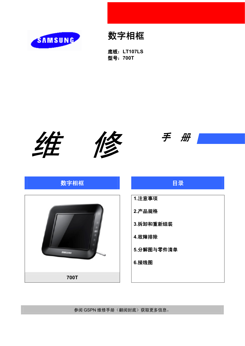
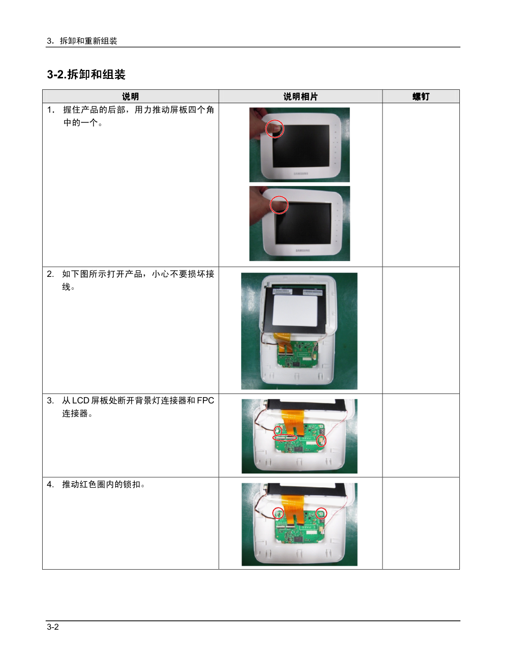
三星700T数码相框维修手册
 "三星700T数码相框维修手册-0")
 "三星700T数码相框维修手册-1")
 "三星700T数码相框维修手册-2")
 "三星700T数码相框维修手册-3")
 "三星700T数码相框维修手册-4")
 "三星700T数码相框维修手册-5")
 "三星700T数码相框维修手册-6")
 "三星700T数码相框维修手册-7")
 "三星700T数码相框维修手册-8")
 "三星700T数码相框维修手册-9")
�
�
�
��
�
�
���
��
��
���
�
��
��
��
��
��������
��
��
��
��
�����
�
�
�
�
�
�
�
�
�
�
�
�
�� � �
�
�
��
�
�
�
�
�
��
�
�
���
��
��
���
�
��
��
��
���
�
�
�
�
�
�
�
�
�
�
�
�
�
�
�
�����
�
������
����
����
�����
������
����
����
�����
���������
�������
�������
��������
������
����
����
�����
����������
��������
��������
���������
����
��
��
���
�
�
��
�
�
�
�
�� ���� ����
����
������
�
�
�
�
�
�� � �
�
�
��
�
��
��
��
���
�
�
����
����
����
�����
��� ������ ����������������������������������������������������������������������������������������������������������������������������� ����
��� ������ ����������������������������������������������������������������������������������������������������������������������������� ����
��� ������ ����������������������������������������������������������������������������������������������������������������������������� ����
��� ����������������������������������������������������������������������������������������� ����
�
�
����
����
����
�����
��� �������������������������������������������������������������������������������������������������������������������������������������� ����
���� �������������������������������������������������������������������������������������������������������������������������������� ����
���� ��������������������������������������������������������������������������������������������������������������������������������������������� ����
���� ��
����
��������������������������������������������������������������������������������������������������������������������� ����
��� �������������������������������������������������������������������������������������� ����
�
�
�������
�������
�������
��������
��� ������� ����������������������������������������������������������������������������������������������������������������������� ����
��� ����������������������������������������������������������������������������������������������� ����
�
�
����
����
����
�����
��� ������� ������������������������������������������������������������������������������������������������������������������������� ����
��� ������������������������������������������������������������������������������������������������������������������������������������������� ����
��� �������������������������������������������������������������������������������������������������������������������������������������� ����
��� ����������������������������������������������������������������������������������������������������������������������������������� ����
��� ������������������������ ����������������������������������������������������������� ����
��� ���������������������������������������������������������������������������������������������� ����
�
�
��������
��������
��������
���������
��� ����� ��������������������������������������������������������������������������������������������������������������������������������� ����
���� ���������������������������������������������������������������������������������������������������������������������������������������� ����
�
�
������
������
������
�������
��� ������������������������������������������������������������������������������������������������������������������������������������������� ����
��� ���� ������������������������������������������������������������������������������������������������������������������������������������ ����
�
�
�
�
�
�
�
�
�
�
�
�
�
�
�
�
�
�
�
�
�
�
�
�
�
�
�
�
�
�
�
�
�
�
�
��������������
��������
��������
����������
�
��
��
��
���
��
��
��
���
���
��������������������������
�����
������������������������
����
����������������������
���
�������������������������
���
������������������������
���
�����������������������
������
����������������������
�
����������������
�
�����������������������
�����
�
�
���������� � � ���� ��
�����
�������������������
�
�
��������
�
����
�
�������
�������
�������
��������
�
��������������
�
��
������������
�����������
�
���
������
������
������
�������
��
��� ��������
�
��� ����
������������
�
��� �����������
�
��� �� ������ �� ���
������
��� ����
�
��� ��� ��� ���
������
�
�
��������
����
�
���������
�����
�����
������
��
��
��
���
����
����
����
�����
��
��
��
���
�
��������
���������
����
�
�
�
�
��� ���������
�������
�
�
�
�
��� � ��� ������������ ���
���
�
�
�
��� ���������
�
�
�
�
�
��������
�
����
�
��
��
��
���
����
����
����
�����
��
��
��
���
��� ��� �����������
�
�
�
�
�����������������
�
� �
�
��������
����
�
���
���
���
����
5-1
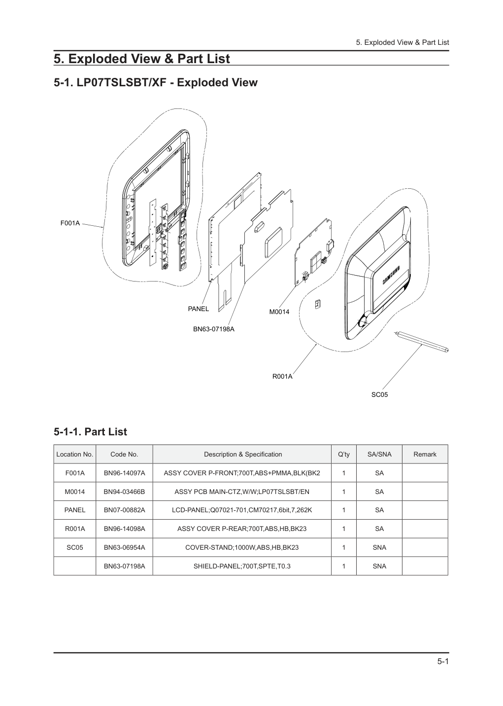
5. Exploded View & Part List
5. Exploded View & Part List
5-1. LP07TSLSBT/XF - Exploded View
F001A
PANEL
BN63-07198A
M0014
R001A
SC05
5-1-1. Part List
Location No.
Code No.
Description & Specification
Q’ty
SA/SNA
Remark
F001A
BN96-14097A
ASSY COVER P-FRONT;700T,ABS+PMMA,BLK(BK2
1
SA
M0014
BN94-03466B
ASSY PCB MAIN-CTZ,W/W;LP07TSLSBT/EN
1
SA
PANEL
BN07-00882A
LCD-PANEL;Q07021-701,CM70217,6bit,7,262K
1
SA
R001A
BN96-14098A
ASSY COVER P-REAR;700T,ABS,HB,BK23
1
SA
SC05
BN63-06954A
COVER-STAND;1000W,ABS,HB,BK23
1
SNA
BN63-07198A
SHIELD-PANEL;700T,SPTE,T0.3
1
SNA
5-2
5. Exploded View & Part List
5-2. LP07TSLSBT/XF - Part List
Service Bom (SA: SERVICE AVAILABLE, SNA: SERVICE NOT AVAILABLE)
Level
Location No.
Code No.
Description & Specification
Q’ty
SA/SNA
Remark
0.1
BN90-02778A
ASSY COVER FRONT;T2(700T)
1
SNA
..2
F001A
BN96-14097A
ASSY COVER P-FRONT;700T,ABS+PMMA,BLK(BK2
1
SA
...3
BN63-06935A
COVER FRONT;700T,ABS+PMMA,HB,BLK(BK27)
1
SNA
...3
BN96-14335A
ASSY BOARD P-KEY FUNCTION;T2,1299-01240-
1
SA
...3
BN61-06407A
GUIDE-CONTROL;700T,ABS,WH13,HB
1
SNA
...3
CCM1
BN63-02183K
COVER-SHEET;Rhcm,PE Vinyl,T 0.04,250MM,2
0.3
SNA
...3
AS078
BN63-06936A
SHEET-FUNCTION;700T,PET,0.3T
1
SNA
...3
BN63-07351A
SHEET-GUIDE;700T,PORON TAPE,0.3T,3mm,77m
1
SNA
0.1
R001A
BN90-02779A
ASSY COVER REAR;T2(700T)
1
SNA
..2
R001A
BN96-14098A
ASSY COVER P-REAR;700T,ABS,HB,BK23
1
SA
...3
R001
BN63-06937A
COVER-REAR;700T,ABS,HB,BK23
1
SNA
....4
BN61-02932G
BRACKET-STOPPER NUT;LED TV,M4,D6,L6.5,BR
1
SNA
...3
M0114
BN61-04467A
HOLDER-WIRE;MONACO,NYNOL66,1.0,NTR
2
SNA
0.1
BN91-04675K
ASSY LCD-CTZ;LP07TSLSBT/EN
1
SNA
..2
PANEL
BN07-00882A
LCD-PANEL;Q07021-701,CM70217,6bit,7,262K
1
SA
0.1
M0017
BN91-04693W
ASSY CHASSIS-CTZ,W/W;LP07TSLSBT/EN
1
SNA
..2
M0014
BN94-03466B
ASSY PCB MAIN-CTZ,W/W;LP07TSLSBT/EN
1
SA
...3
0202-001463
SOLDER-WIRE;LFC2-W3.0,-,D3,99.79Sn/0.2Cu
0.325
SNA
...3
0202-001608
SOLDER-WIRE FLUX;LFC7-107,D0.8,99.3Sn/0.
0.003
SNA
...3
0204-002420
SOLVENT;1M-1000,C3H70H,96
5.84
SNA
...3
0204-002607
FLUX;DF-234U,13%,14KG,Gravity 0.82
3.801
SNA
...3
BN97-04294B
ASSY SMD;LP07TSLSBT/EN,BN41-0*
1
SNA
....4
0202-001477
SOLDER-CREAM;LST309-M,D20~45um,96.5Sn/3A
1.026
SNA
....4
DS01A
0401-001056
DIODE-SWITCHING;MMBD4148SE,100V,200mA,SO
2
SA
....4
D1
0401-001099
DIODE-SWITCHING;1N4148WS,75V,150mA,SOD-3
3
SA
....4
D0254
0402-000553
DIODE-SCHOTTKY;SS24/B240,40V,2000mA,DO-2
5
SA
....4
0403-000584
DIODE-ZENER;VLZ3V6B,3.6/3.845V,500mW,SOD
2
SNA
....4
0403-000607
DIODE-ZENER;VLZ16C,15.69/16.51V,500mW,SO
1
SA
....4
0403-001137
DIODE-ZENER;VLZ9V1B,8.57/9.01V,500mW,SOD
1
SNA
....4
MZD1
0403-001411
DIODE-ZENER;5.49-5.73V,200mW,SOD-323,TP
1
SA
....4
0403-001784
DIODE-ZENER;NZH7V5C,7.29/7.67V,500mW,SOD
1
SNA
....4
0406-001181
DIODE-TVS;NUP4201MR6,6/-/-V,500W,TSOP-6
1
SA
....4
PQ02
0501-002080
TR-SMALL SIGNAL;2SC2412K,NPN,200mW,SC-59
2
SA
....4
Q409
0505-001165
FET-SILICON;Si3443CDV,P,-20V,+-4.4A,65mo
2
SA
....4
1001-001481
IC-ANALOG SWITCH;FSUSB42UMX,USB SWITCH,U
1
SNA
....4
IC113
1105-001357
IC-DRAM;K4S281632,128NBit,4x2Mx16,TSOP(I
1
SNA
....4
T0087
1203-002302
IC-POSI.FIXED REG.;78RM33D,D-PAK,3P,-,PL
1
SA
....4
1203-003615
IC-DC/DC CONVERTER;MP1541DJ,TSOT-23,5P,2
2
SNA
....4
1203-005279
IC-DC/DC CONVERTER;MP2372DN,SOP,8P,4.9x3
1
SA
....4
1204-003061
IC-DECODER;MP630DTCG-B,TQFP,144P,16x16x1
1
SA
....4
P803T
1404-001457
THERMISTOR-PTC;0.2/0.8ohm,13.2V,100A,1.1
1
SNA
....4
1405-001185
VARISTOR;24Vdc,1.6x0.8x0.36mm,TP
4
SA
....4
HD9
1405-001192
VARISTOR;12Vdc,30A,1.6x0.8x0.55mm,TP
2
SA
....4
KAR21
2007-000070
R-CHIP;0ohm,5%,1/10W,TP,1608
1
SA
....4
AR49
2007-000140
R-CHIP;1Kohm,5%,1/16W,TP,1005
9
SNA
....4
R319
2007-000143
R-CHIP;4.7Kohm,5%,1/16W,TP,1005
12
SNA
5-3
5. Exploded View & Part List
Level
Location No.
Code No.
Description & Specification
Q’ty
SA/SNA
Remark
....4
2007-000146
R-CHIP;6.8Kohm,5%,1/16W,TP,1005
1
SNA
....4
R104
2007-000148
R-CHIP;10Kohm,5%,1/16W,TP,1005
30
SA
....4
DR39
2007-000162
R-CHIP;100Kohm,5%,1/16W,TP,1005
2
SNA
....4
R111
2007-000171
R-CHIP;0ohm,5%,1/16W,TP,1005
4
SNA
....4
R691
2007-000572
R-CHIP;220ohm,5%,1/8W,TP,2012
1
SA
....4
2007-000710
R-CHIP;3.9Kohm,5%,1/8W,TP,2012
1
SC
....4
DR37
2007-000932
R-CHIP;470ohm,5%,1/16W,TP,1005
1
SNA
....4
R3505
2007-000950
R-CHIP;47ohm,5%,1/4W,TP,3216
3
SA
....4
S1G0843
2007-001125
R-CHIP;68Kohm,1%,1/10W,TP,1608
2
SA
....4
R16
2007-001313
R-CHIP;330ohm,5%,1/16W,TP,1005
1
SNA
....4
2007-001319
R-CHIP;1.2Kohm,5%,1/16W,TP,1005
1
SNA
....4
TR30
2007-007009
R-CHIP;75ohm,5%,1/16W,TP,1005
1
SNA
....4
R365
2007-007107
R-CHIP;100Kohm,1%,1/16W,TP,1005
2
SNA
....4
2007-007132
R-CHIP;15Kohm,1%,1/16W,TP,1005
1
SA
....4
2007-007136
R-CHIP;4.7Kohm,1%,1/16W,TP,1005
1
SNA
....4
2007-007138
R-CHIP;27Kohm,1%,1/16W,TP,1005
1
SA
....4
2007-007156
R-CHIP;1ohm,5%,1/16W,TP,1005
5
SNA
....4
2007-007305
R-CHIP;120ohm,1%,1/16W,TP,1005
1
SNA
....4
MR601
2007-007307
R-CHIP;150ohm,1%,1/16W,TP,1005
1
SNA
....4
2007-007313
R-CHIP;6.8Kohm,1%,1/16W,TP,1005
1
SA
....4
2007-007318
R-CHIP;1Kohm,1%,1/16W,TP,1005
2
SNA
....4
2007-007352
R-CHIP;130Kohm,1%,1/10W,TP,1608
1
SA
....4
2007-007469
R-CHIP;110ohm,1%,1/16W,TP,1005
1
SNA
....4
2007-007517
R-CHIP;240ohm,1%,1/16W,TP,1005
1
SNA
....4
2007-007528
R-CHIP;1.5Kohm,1%,1/16W,TP,1005
3
SA
....4
2007-007698
R-CHIP;5.1Kohm,1%,1/16W,TP,1005
1
SNA
....4
2007-007766
R-CHIP;2Kohm,1%,1/16W,TP,1005
1
SNA
....4
2007-007861
R-CHIP;62Kohm,1%,1/16W,TP,1005
1
SA
....4
2007-007942
R-CHIP;1Mohm,1%,1/16W,TP,1005
1
SA
....4
MR11
2007-008015
R-CHIP;75ohm,1%,1/16W,TP,1005
1
SNA
....4
2007-008175
R-CHIP;330ohm,1%,1/16W,TP,1005
1
SNA
....4
2007-008294
R-CHIP;33ohm,1%,1/16W,TP,1005
9
SA
....4
ZRN10
2011-001261
R-NETWORK;33ohm,5%,1/16W,L,CHIP,8P,TP,2.
4
SA
....4
DC54
2203-000278
C-CER,CHIP;.01nF,0.5pF,50V,C0G,TP,1005
1
SA
....4
DC1
2203-000386
C-CER,CHIP;.015nF,5%,50V,C0G,TP,1005
4
SA
....4
C507
2203-000489
C-CER,CHIP;2.2nF,10%,50V,X7R,TP,1005
1
SA
....4
HDC5
2203-001072
C-CER,CHIP;0.056nF,5%,50V,NP0,1005
21
SA
....4
AC28
2203-001607
C-CER,CHIP;0.22nF,5%,50V,NP0,1608
1
SA
....4
C637
2203-001656
C-CER,CHIP;0.47nF,5%,50V,NP0,1608
1
SNA
....4
AD480
2203-002525
C-CER,CHIP;0.56nF,10%,50V,X7R,TP,1005
1
SNA
....4
AC2
2203-002711
C-CER,CHIP;100nF,10%,25V,X7R,1608
2
SA
....4
DC108
2203-005005
C-CER,CHIP;100nF,10%,16V,X7R,1608
1
SC
....4
AD480
2203-005054
C-CER,CHIP;0.0047nF,0.25pF,50V,NP0,TP,10
4
SA
....4
AC611
2203-005194
C-CER,CHIP;.22nF,10%,50V,X7R,TP,1608
1
SA
....4
TE3
2203-005261
C-CER,CHIP;1000nF,10%,25V,X7R,TP,3216
4
SNA
....4
C102
2203-006158
C-CER,CHIP;100nF,10%,16V,X7R,1005
31
SNA
....4
AD480
2203-006333
C-CER,CHIP;10000nF,20%,16V,X5R,TP,3216
20
SNA
....4
AD480
2203-006336
C-CER,CHIP;10000nF,10%,25V,X5R,3216
4
SA
....4
AD480
2203-006460
C-CER,CHIP;2200nF,10%,16V,X5R,1608
3
SA
5-4
5. Exploded View & Part List
Level
Location No.
Code No.
Description & Specification
Q’ty
SA/SNA
Remark
....4
HDC11
2203-006562
C-CER,CHIP;1000nF,10%,10V,X5R,TP,1005
13
SNA
....4
AD480
2203-006636
C-CER,CHIP;220nF,10%,25V,X7R,1608
2
SA
....4
2409-001168
C-EDL;200000uF,3.3V,0.01mA,TP,D6.8x11.3m
1
SA
....4
X202
2801-000258
CRYSTAL-SMD;0.032768MHz,20ppm,SMD,12.5pF
1
SA
....4
X202
2801-003948
CRYSTAL-SMD;12MHz,30ppm,28-AAN,12pF,60oh
1
SA
....4
T0568
3301-001594
BEAD-SMD;90ohm,2.0*1.2*1.3mm,TP,-,-
2
SNA
....4
3601-001470
FUSE-SURFACE MOUNT;32V,1.5A,FAST-ACTING,
1
SNA
....4
AC510
3708-002285
CONNECTOR-FPC/FFC/PIC;30 P,0.5mm,SMD-A,A
2
SNA
....4
3709-001526
CONNECTOR-CARD SLOT;9P,2.5mm,SMD-A,Au,2
1
SNA
....4
CN906
3711-005484
CONNECTOR-HEADER;BOX,2P,1R,3.5MM,STRAIGH
1
SNA
....4
HB01A
3711-005743
HEADER-BOARD TO CABLE;BOX,5P,1R,1.25mm,A
1
SA
....4
3722-002528
JACK-USB;5P,AU30U,BLK,SMD-A,MINI USB B
1
SA
....4
3722-002894
JACK-USB;4P,Au 30/ Ni 80,BLK,SMD-A,A-TYP
1
SA
....4
3722-002895
JACK-DC POWER;2P,4.4PI,nickel,black
1
SA
....4
T0010
BN27-00007A
COIL CHOKE-SMD;DHB0504-100,RB15/17NS,10u
3
SA
....4
BN41-01431A
PCB MAIN;700T,FR-4,1,1.0,1.2,105X75mm,4,
1
SNA
....4
BN61-03631A
BRACKET-FINGER;Creta Entry,BeCu 1/4H,0.1
7
SNA
....4
BN97-04035L
ASSY MICOM-MAIN,CTZ,W/W;LP07TSLSBT/EN,BN
1
SNA
.....5
NAND2
1107-001774
IC-NAND FLASH;K9G8G08U0A-PCB0,1GByte,1Gx
1
SNA
....4
BN97-04035M
ASSY MICOM-SUB,CTZ,W/W;LP07TSLSBT/EN,BN4
1
SNA
.....5
IC520
0903-001624
IC-MICROCONTROLLER;WT6703F,SSOP,24P,8.7x
1
SA
....4
T0087
1203-006136
IC-POSI.FIXED REG.;AP1117D-18-GZ-13-89,T
1
SA
....4
1203-006266
IC-POSI.FIXED REG.;AP1117E33GZ-13-89,SOT
1
SA
....4
2007-000039
R-CHIP;0ohm,1%,1/10W,TP,1608
1
SA
....4
2007-000147
R-CHIP;8.2Kohm,5%,1/16W,TP,1005
1
SNA
....4
PR4
2007-000265
R-CHIP;1.8Kohm,1%,1/10W,TP,1608
1
SA
....4
CER42
2007-000999
R-CHIP;510ohm,1%,1/10W,TP,1608
2
SA
....4
R8
2007-007721
R-CHIP;560ohm,1%,1/10W,TP,1608
2
SA
....4
2007-008563
R-CHIP;270ohm,1%,1/16W,TP,1005
2
SA
....4
AD480
2203-000204
C-CER,CHIP;100nF,10%,25V,X7R,2012
2
SNA
....4
T0568
3301-001404
BEAD-SMD;30ohm,2012,TP,15.9OHM/30MHz
5
SA
....4
AC109
2203-000783
C-CER,CHIP;0.33nF,5%,50V,C0G,1608
2
SA
....4
AD480
2203-002720
C-CER,CHIP;10nF,10%,25V,X7R,TP,1005
1
SNA
....4
R102
2007-000149
R-CHIP;12Kohm,5%,1/16W,TP,1005
1
SA
...3
M2893
BN39-00862F
LEAD CONNECTOR;DH0802-022A,UL1571#30,157
1
SA
...3
T0186
BN64-00951A
INLAY-PLATE;MONACO,PS SHEET,0.5,43,9,BLA
1
SNA
0.1
BN91-05505A
ASSY SHIELD;T2(700T)
1
SNA
..2
BN63-07198A
SHIELD-PANEL;700T,SPTE,T0.3
1
SNA
..2
CIS1
BN74-00021A
TAPE-FILAMENT;Filament tape,clear,#8915,
0.05
SNA
..2
BN63-07329A
GASKET;Conductive Fabric,0.07mm,88mm,40m
1
SNA
0.1
T0527
BN92-03547A
ASSY LABEL;LP07MNLSBT/EN
1
SNA
..2
CCM1
BN68-01588A
LABEL RATING;SPF-75H,WW,PET,T0.05,105,14
1
SNA
0.1
BN92-05638X
ASSY P/MATERIAL;LP07TSLSBT/EN
1
SNA
..2
T0214
0203-001595
TAPE-OPP MASKING;OPP-2,0.075,75,800M,CLR
1.32
SNA
..2
6902-000061
BAG AIR;LDPE,T0.2,W500,L1000,TRP,370.000
1
SNA
..2
6902-000379
BAG AIR;LDPE,T0.2,W1000,L1800,TRP,1260.0
1
SNA
..2
6902-000604
BAG WRAPPING;LDPE,T0.02,W500,L10000,TRP,
1.85
SNA
..2
6902-000609
BAG ROLL;LDPE,T0.05,W2400,L1000,TRP,30.0
0.04
SNA
..2
T0524
6902-001059
BAG PE;HDPE/NITRON,T0.015/T0.5,W200,L300
1
SNA
..2
AA69-03854A
PAD-PLATE;CB,SW,605,425
1
SNA
5-5
5. Exploded View & Part List
Level
Location No.
Code No.
Description & Specification
Q’ty
SA/SNA
Remark
..2
T0527
BH68-40364A
LABEL-SUMMARY;G52,G72,ART,100G,WHT,BLK,W
1
SNA
..2
BH69-00403A
PALLET-PACKING;KR17LO,WOOD,1070,1034,120
1
SNA
..2
BH69-00457F
PACKING INNER-PAD;ALL MODEL,EPE,SHEET,W1
1
SNA
..2
T0527
BN68-00129A
LABEL SHIPPING-00;LABEL SHIPPING,ART-PAP
1
SNA
..2
BN69-00391D
PAD-ANGLE;DI19PS,OTHER,T4,50,2000,YEL
1
SNA
..2
BN69-04939A
CUSHION-BLISTER;700T,1.0,BLK
1
SNA
0.1
BN92-05993E
ASSY BOX;LP07TSLSBT/EN
1
SNA
..2
BH68-20015B
LABEL BAR CODE-00;ALL MODEL,MOJO 90G,90,
1
SNA
..2
T0527
BN68-00134L
LABEL-BOX,01;ALL MODEL,MOJO 90G,120X90,W
1
SNA
..2
BN69-04994A
BOX-01,SET;LP07T2,CB,NON-STANDARD,SW,W10
1
SNA
..2
BN69-04995A
BOX-MASTER;LP07T2,CB,A1,W362,D388,H158,A
1
SNA
0.1
ACCE1
BN92-06264S
ASSY ACCESSORY;LP07TSLSBT/XF
1
SNA
..2
T0268
3903-000381
CBF-POWER CORD;DT,CHINA,LSG-21,250/250V,
1
SA
..2
EC34
BN39-01044D
AV OUT CABLE-USB;IPANEMA,4p/5p,UL2725_US
1
SA
..2
M0158
BN44-00133C
DC VSS(A);SAD1212,IPANEMA/SWAN,110/230V,
1
SA
..2
M9889
BN63-02368B
CLOTH-CLEAN;cloth,120,160,sea blue,ToC
1
SA
..2
SC05
BN63-06954A
COVER-STAND;1000W,ABS,HB,BK23
1
SNA
...3
BN61-06405A
STAND-BAR;1000W,SUM24,4,110,NI,INSERT
1
SNA
..2
ACCE1
BN96-14858D
ASSY ACCESSORY;LP07TSLSBT/XF
1
SNA
...3
T0524
6902-000110
BAG PE;LDPE,T0.05,W250,L400,TRP,28,2,9.2
1
SNA
...3
T0527
AA68-00764A
LABEL-PASSING;SAMSUNG ALL,ART PAPER,CLR,
1
SNA
...3
AA68-03242S
MANUAL FLYER-SAFETY GUIDE;comm,Samsung,1
1
SNA
...3
T0527
BN68-00513A
LABEL-E,PASS;ALL MODEL,YUPO(110G),50X15,
1
SNA
...3
BN68-01789A
MANUAL FLYER-WARRANTY CARD;Chinese,Art 1
1
SNA
...3
BN68-02886B
MANUAL USERS;700T,Samsung,6Lang,Asia,W/P
1
SNA
...3
BN68-02886D
MANUAL FLYER;700T,Samsung,22Lang,Korea,W
1
SNA
5-6
5. Exploded View & Part List
Memo
1-1
1. Precautions
1. Precautions
1-1. Safety Precautions
Follow these safety, servicing and ESD precautions to prevent damage and to protect against potential hazards such as
electrical shock.
1-1-1. Warnings
For continued safety, do not attempt to modify the circuit board.
1.
Disconnect the AC power and DC power jack before servicing.
2.
1-1-2. Servicing the LCD Monitor
When servicing the LCD Monitor, Disconnect the AC line cord from the AC outlet.
1.
It is essential that service technicians have an accurate voltage meter available at all times. Check the calibration of
2.
this meter periodically.
1-1-3. Fire and Shock Hazard
Before returning the monitor to the user, perform the following safety checks:
Inspect each lead dress to make certain that the leads are not pinched or that hardware is not lodged between the
1.
chassis and other metal parts in the monitor.
Inspect all protective devices such as nonmetallic control knobs, insulating materials, cabinet backs, adjustment and
2.
compartment covers or shields, isolation resistorcapacitor networks, mechanical insulators, etc.
Leakage Current Hot Check (Figure 1-1):
3.
WARNING : Do not use an isolation transformer during this test.
Use a leakage current tester or a metering system that complies with American National Standards Institute (ANSI
C101.1, Leakage Current for Appliances), and Underwriters Laboratories (UL Publication UL1410, 59.7).
With the unit completely reassembled, plug the AC line cord directly into a 120V AC outlet. With the unit’s AC switch
4.
first in the ON position and then OFF, measure the current between a known earth ground (metal water pipe, conduit,
etc.) and all exposed metal parts, including: metal cabinets, screwheads and control shafts.
The current measured should not exceed 0.5 milliamp.
Reverse the power-plug prongs in the AC outlet and repeat the test.
1-1-4. Product Safety Notices
Some electrical and mechanical parts have special safetyrelated characteristics which are often not evident from visual
inspection. The protection they give may not be obtained by replacing them with components rated for higher voltage,
wattage, etc. Parts that have special safety characteristics are identified by
on schematics and parts lists. A substitute
replacement that does not have the same safety characteristics as the recommended replacement part might create
shock, fire and/or other hazards. Product safety is under review continuously and new instructions are issued whenever
appropriate.
DEVICE
UNDER
TEST
(READING SHOULD)
NOT BE ABOVE 0.5mA
LEAKAGE
CURRENT
TESTER
TEST ALL
EXPOSED METAL
SURFACES
2-WIRE CORD
*ALSO TEST WITH
PLUG REVERSED
(USING AC ADAPTER
PLUG AS REQUIRED)
EARTH
GROUND
Figure 1-1. Leakage Current Test Circuit
1-2
1. Precautions
1-2. Servicing Precautions
WARNING:
An electrolytic capacitor installed with the wrong polarity might explode.
Caution:
Before servicing units covered by this service manual, read and follow the Safety Precautions section of
this manual.
Note:
If unforeseen circumstances create conflict between the following servicing precautions and any of the
safety precautions, always follow the safety precautions.
1-2-1 General Servicing Precautions
Always unplug the unit’s AC power cord from the AC power source and disconnect the DC Power Jack before
1.
attempting to:
(a) remove or reinstall any component or assembly, (b) disconnect PCB plugs or connectors, (c) connect a test
component in parallel with an electrolytic capacitor.
Some components are raised above the printed circuit board for safety. An insulation tube or tape is sometimes
2.
used. The internal wiring is sometimes clamped to prevent contact with thermally hot components. Reinstall all such
elements to their original position.
After servicing, always check that the screws, components and wiring have been correctly reinstalled. Make sure that
3.
the area around the serviced part has not been damaged.
Check the insulation between the blades of the AC plug and accessible conductive parts (examples: metal panels,
4.
input terminals and earphone jacks).
Insulation Checking Procedure: Disconnect the power cord from the AC source and turn the power switch ON.
5.
Connect an insulation resistance meter (500 V) to theblades of the AC plug.
The insulation resistance between each blade of the AC plug and accessible conductive parts (see above) should be
greater than 1 megohm.
Always connect a test instrument’s ground lead to the instrument chassis ground before connecting the positive lead;
6.
always remove the instrument’s ground lead last.
1-3. Static Electricity Precautions
Some semiconductor (solid state) devices can be easily damaged by static electricity. Such components are commonly
called Electrostatically Sensitive Devices (ESD). Examples of typical ESD are integrated circuits and some field-effect
transistors. The following techniques will reduce the incidence of component damage caused by static electricity.
Immediately before handling any semiconductor components or assemblies, drain the electrostatic charge from your
1.
body by touching a known earth ground. Alternatively, wear a discharging wrist-strap device. To avoid a shock hazard,
be sure to remove the wrist strap before applying power to the monitor.
After removing an ESD-equipped assembly, place it on a conductive surface such as aluminum foil to prevent
2.
accumulation of an electrostatic charge.
Do not use freon-propelled chemicals. These can generate electrical charges sufficient to damage ESDs.
3.
Use only a grounded-tip soldering iron to solder or desolder ESDs.
4.
Use only an anti-static solder removal device. Some solder removal devices not classified as “anti-static” can generate
5.
electrical charges sufficient to damage ESDs.
Do not remove a replacement ESD from its protective package until you are ready to install it. Most replacement ESDs
6.
are packaged with leads that are electrically shorted together by conductive foam, aluminum foil or other conductive
materials.
Immediately before removing the protective material from the leads of a replacement ESD, touch the protective
7.
material to the chassis or circuit assembly into which the device will be installed.
Caution: Be sure no power is applied to the chassis or circuit and observe all other safety precautions.
Minimize body motions when handling unpackaged replacement ESDs. Motions such as brushing clothes together,
8.
or lifting your foot from a carpeted floor can generate enough static electricity to damage an ESD.
1-3
1. Precautions
1-4. Installation Precautions
Keep the power cord away from any heat emitting devices, as a melted covering may cause fire or electric shock.
1.
Do not place the product in areas with poor ventilation such as a bookshelf or closet. The increased internal
2.
temperature may cause fire.
Make sure to turn the power off and unplug the power cord from the outlet before repositioning the product. Also check
3.
the antenna cable or the external connectors if they are fully unplugged. Damage to the cord may cause fire or electric
shock.
Keep the antenna far away from any high-voltage cables and install it firmly. Contact with the highvoltage cable or the
4.
antenna falling over may cause fire or electric shock.
When installing the product, leave enough space (10cm) between the product and the wall for ventilation purposes.
5.
A rise in temperature within the product may cause fire.
1-4
1. Precautions
Memo
2-1
2. Product specifications
2. Product specifications
2-1. Feature & Specifications
Model
700T
Features
Various slideshow effects
ሪ
Light in weight and moderately priced
ሪ
Neat design and two exterior color choices
ሪ
Clock feature
ሪ
Specifications
Panel
Type
7”TFT LCD / CMO
Resolution
800 x 600
Brightness
250cd/m2
Contrast Ratio
400:1
Viewing Angle
50/70/70/70 (U/D/L/R)
Interface
Digital TTL 6 bit (18bit)
Response Time
20msec (Tr + Tf)
Storage
Flash Memory
10MByte (Code) , 990MByte (User)
Main Memory
16MByte SDRAM
Supported Image File Formats
JPEG files, except for progressive or CMYK format images.
Supported Music File Formats
None
USB
Host(USB2.0) x 1, Slave(USB2.0) x 1
Memorys
SD
Power
Rating
4.6W (typ)
External Power Adapter (12V, 1A, 12W)
Browse
Contents
Image View
Slide Show / Interval / Slide Show Effect / Rotate / Zoom / Thumbnail View
Control
I/O Device
Key Button (8 keys) + Power button (1 key)
File Management
Image copy, delete
Dimensions (mm)
200.7 (W) x 165.3 (H) x 30.0 (D)
Weight
350g
2-2
2. Product specifications
2-2. Spec Comparison to the Old Models
Model
700T
TIVOLI2 (SPF-71ES)
Design
Penel Type
7”TFT LCD / CMO
7” TFT LCD (Analog) / Hannstar
Resolution
800 x 600
480 x 234
Response Time
20ms (Tr + Tf)
25 ms
Brightness
250 cd/2
200 cd/2
Contrast Ratio
400 : 1
500 : 1
Viewing Angle
50/70/70/70 (U/D/L/R)
60/70/60/60 (U/D/L/R)
Color
Black / White 2 Type
White / Black / Pink 3 Type
Support Contents
Format
JPG
JPG
Internal Memory
900MB
900MB
2-3
2. Product specifications
2-3. Accessories
Product
Description
Ccde. No
Remark
Power Cord
3903-000055
Samsung Electronics
Service center
Adapter
BN44-00133C
USB Cable
BN39-01044D
User’s Guide
BN68-01567D
Warranty
BN68-00226R
2-4. Accessories (Sold Separately)
Product
Description
Code. No
SD
-
2-4
2. Product specifications
2-5. The Control Panel and Its Functions
2-5-1. Function Button Descriptions
Turns power on and off.
Opens or closes the menu.
Navigates or changes options on the menu.
Selects an option on the menu.
Returns to the previous menu.
(Moves to the main screen if pressed for 2
seconds.)
Starts a slide show.
2-5
2. Product specifications
2-5-2. Menu Options
Use the buttons on the product to set various functions to your preferences.
Photo
Home
Moves to the main screen.
Copy
If an external memory device (SD memory card/ USB memory device) is connected to the product,
• Copies pictures in an external memory device to the internal memory.
• Copies pictures in the internal memory to an external memory device.
Delete
Deletes pictures in the internal memory or an external memory device.
Select Multiple Files
Selects multiple files to run functions like slide show, copy, delete, etc.
Select Storage
Device
If an external memory device (SD memory card/USB memory device) is connected to the product,
• Select the internal memory or an external memory device (SD memory card/USB memory device).
Settings
Clock
The current time configured in
版权声明
1. 本站所有素材,仅限学习交流,仅展示部分内容,如需查看完整内容,请下载原文件。
2. 会员在本站下载的所有素材,只拥有使用权,著作权归原作者所有。
3. 所有素材,未经合法授权,请勿用于商业用途,会员不得以任何形式发布、传播、复制、转售该素材,否则一律封号处理。
4. 如果素材损害你的权益请联系客服QQ:77594475 处理。