NEC 65PWB31显示器维修手册
 "NEC 65PWB31显示器维修手册-0")
 "NEC 65PWB31显示器维修手册-1")
 "NEC 65PWB31显示器维修手册-2")
 "NEC 65PWB31显示器维修手册-3")
 "NEC 65PWB31显示器维修手册-4")
 "NEC 65PWB31显示器维修手册-5")
 "NEC 65PWB31显示器维修手册-6")
 "NEC 65PWB31显示器维修手册-7")
 "NEC 65PWB31显示器维修手册-8")
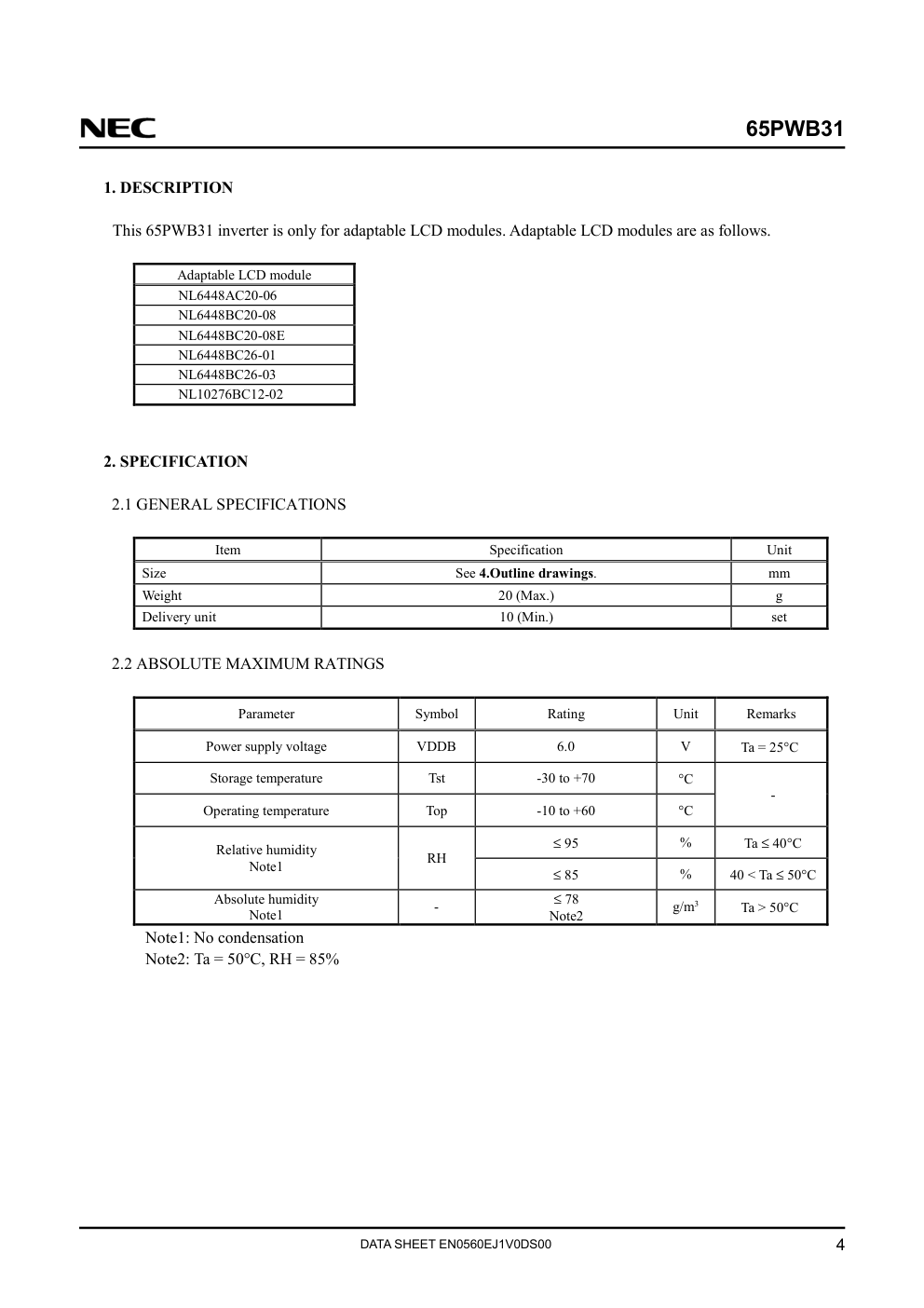
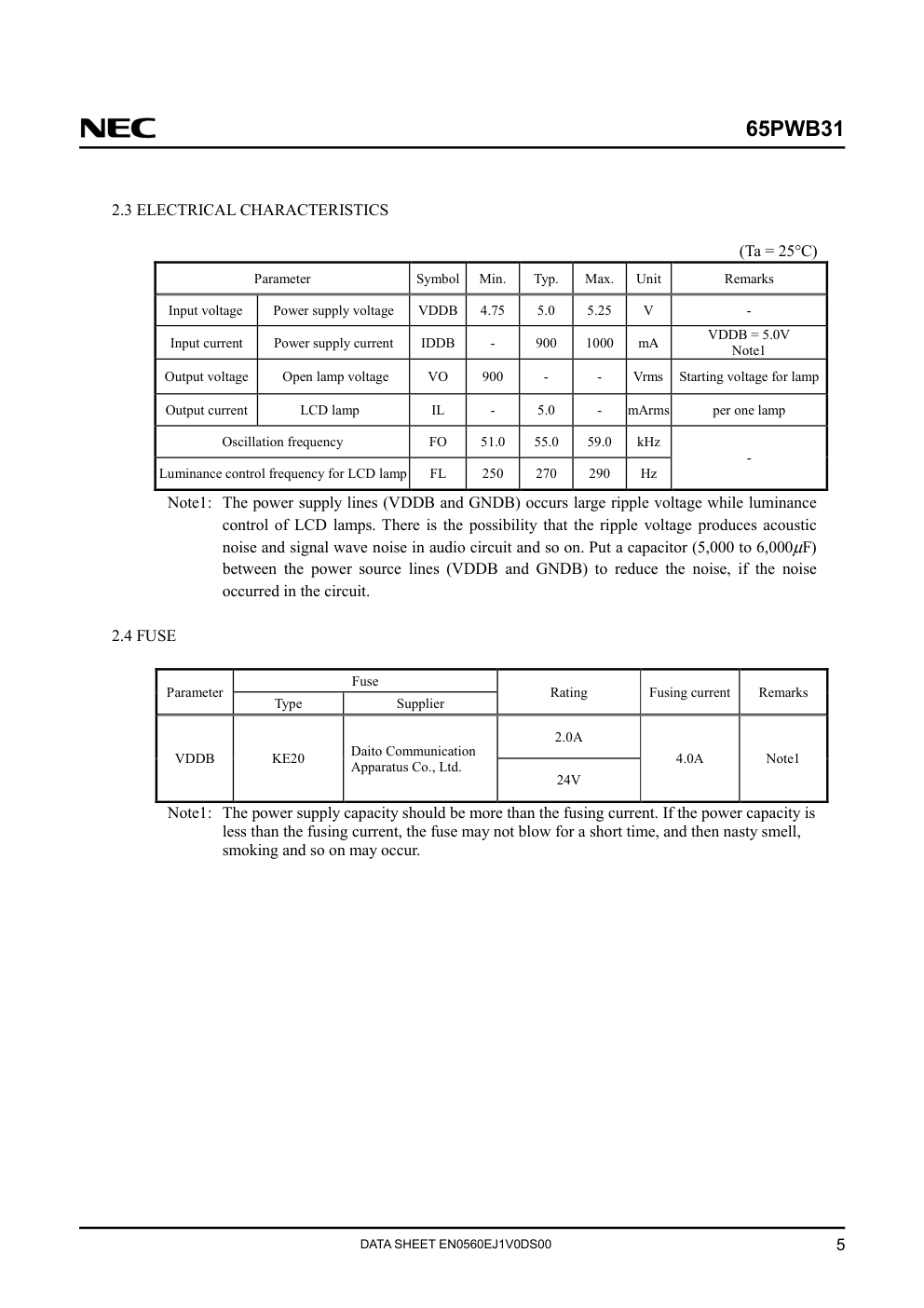
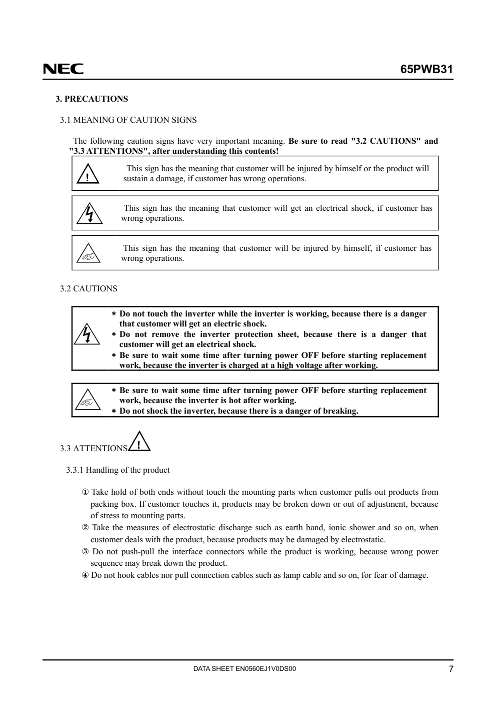
Document Number: EN0560EJ1V0DS00 (1st edition) Published date: June 2002 N CP (N) � NEC Corporation 2002 All rights reserved. All information is subject to change without notice. Please confirm the delivery specification before starting to design your system. 1 INVERTER 65PWB31 DATA SHEET (1st edition) 65PWB31 DATA SHEET EN0560EJ1V0DS00 2 INTRODUCTION No part of this document shall be copied in any form or by any means without the prior written consent of NEC Corporation. NEC Corporation does not assume any liability for infringement of patents, copyrights or other intellectual property rights of third parties by or arising from use of a product described herein or any other liability arising from use of such application. No license, express, implied or otherwise, is granted under any patents, copyrights or other intellectual property rights of NEC Corporation or of others. While NEC Corporation has been making continuous effort to enhance the reliability of its products, the possibility of failures cannot be eliminated entirely. To minimize risks of damage to property or injury to person arising from a failure in an NEC product, customers must incorporate sufficient safety measures in their design, such as redundancy, fire-containment and anti-failure features. NEC products are classified into the following three quality grades: " S t a n d a r d " , " S p e c i a l " , " S p e c i f i c " The "Specific" quality grade applies only to applications developed based on a customer designated "quality assurance program" for a specific application. The recommended applications of a product depend on its quality grade, as indicated below. Customers must check the quality grade of each application before using it in a particular application. Standard: Computers, office equipment, communications equipment, test and measurement equipment, audio and visual equipment, home electronic appliances, machine tools, personal electronic equipment and industrial robots Special: Transportation equipment (automobiles, trains, ships, etc.), traffic control systems, anti-disaster systems, anti-crime systems, safety equipment and medical equipment (not specifically designed for life support) Specific: Military systems, aircraft, aerospace equipment, submersible repeaters, nuclear reactor control systems, life support systems (medical equipment, etc.) and any other equipment The quality grade of this product is "Standard" unless otherwise specified in this document. If customers intend to use this product for applications other than those specified for "Standard" quality grade, they should contact NEC Corporation sales representative in advance. Anti-radioactive design is not implemented in this product. 65PWB31 DATA SHEET EN0560EJ1V0DS00 3 CONTENTS INTRODUCTION.......................................................................................................................................... 2 1. DESCRIPTION.......................................................................................................................................... 4 2. SPECIFICATION ...................................................................................................................................... 4 2.1 GENERAL SPECIFICATIONS............................................................................................................. 4 2.2 ABSOLUTE MAXIMUM RATINGS.................................................................................................... 4 2.3 ELECTRICAL CHARACTERISTICS .................................................................................................. 5 2.4 FUSE...................................................................................................................................................... 5 2.5 CONNECTIONS AND FUNCTIONS FOR INTERFACE PINS.......................................................... 6 3. PRECAUTIONS......................................................................................................................................... 7 3.1 MEANING OF CAUTION SIGNS ....................................................................................................... 7 3.2 CAUTIONS ........................................................................................................................................... 7 3.3 ATTENTIONS........................................................................................................................................ 7 3.3.1 Handling of the product................................................................................................................. 7 3.3.2 Environment.................................................................................................................................. 8 3.3.3 Other.............................................................................................................................................. 8 4. OUTLINE DRAWINGS ............................................................................................................................ 9 65PWB31 DATA SHEET EN0560EJ1V0DS00 4 1. DESCRIPTION This 65PWB31 inverter is only for adaptable LCD modules. Adaptable LCD modules are as follows. Adaptable LCD module NL6448AC20-06 NL6448BC20-08 NL6448BC20-08E NL6448BC26-01 NL6448BC26-03 NL10276BC12-02 2. SPECIFICATION 2.1 GENERAL SPECIFICATIONS Item Specification Unit Size See 4.Outline drawings. mm Weight 20 (Max.) g Delivery unit 10 (Min.) set 2.2 ABSOLUTE MAXIMUM RATINGS Parameter Symbol Rating Unit Remarks Power supply voltage VDDB 6.0 V Ta = 25°C Storage temperature Tst -30 to +70 °C Operating temperature Top -10 to +60 °C - ≤ 95 % Ta ≤ 40°C Relative humidity Note1 RH ≤ 85 % 40 < Ta ≤ 50°C Absolute humidity Note1 - ≤ 78 Note2 g/m3 Ta > 50°C Note1: No condensation Note2: Ta = 50°C, RH = 85% 65PWB31 DATA SHEET EN0560EJ1V0DS00 5 2.3 ELECTRICAL CHARACTERISTICS (Ta = 25°C) Parameter Symbol Min. Typ. Max. Unit Remarks Input voltage Power supply voltage VDDB 4.75 5.0 5.25 V - Input current Power supply current IDDB - 900 1000 mΑ VDDB = 5.0V Note1 Output voltage Open lamp voltage VO 900 - - Vrms Starting voltage for lamp Output current LCD lamp IL - 5.0 - mArms per one lamp Oscillation frequency FO 51.0 55.0 59.0 kHz Luminance control frequency for LCD lamp FL 250 270 290 Hz - Note1: The power supply lines (VDDB and GNDB) occurs large ripple voltage while luminance control of LCD lamps. There is the possibility that the ripple voltage produces acoustic noise and signal wave noise in audio circuit and so on. Put a capacitor (5,000 to 6,000µF) between the power source lines (VDDB and GNDB) to reduce the noise, if the noise occurred in the circuit. 2.4 FUSE Fuse Parameter Type Supplier Rating Fusing current Remarks 2.0A VDDB KE20 Daito Communication Apparatus Co., Ltd. 24V 4.0A Note1 Note1: The power supply capacity should be more than the fusing current. If the power capacity is less than the fusing current, the fuse may not blow for a short time, and then nasty smell, smoking and so on may occur. 65PWB31 DATA SHEET EN0560EJ1V0DS00 6 2.5 CONNECTIONS AND FUNCTIONS FOR INTERFACE PINS CN1 socket (Inverter side): IL-Z-6PL-SMTY (Japan Aviation Electronics Industry Limited (JAE)) Adaptable plug: IL-Z-6S-S125C3 (Japan Aviation Electronics Industry Limited (JAE)) Pin No. Symbol Function Remarks 1 GNDB Backlight ground - 2 GNDB Backlight ground - 3 VDDB Power supply - 4 VDDB Power supply - 5 BRTL Luminance control input Note1 6 BRTH Luminance control input Note1, Note2 Note1: A way of luminance control by a variable resistor. Mating variable resistor: 10 kΩ±5 % Minimum luminance (30%) : R = 0 Ω Maximum luminance (100%): R = 10 kΩ Note2: A way of luminance control by a voltage. The range of input voltage between BRTH and GNDB is as follows. NL6448AC20-06 Minimum luminance (30%): 1.5V Maximum luminance (100%): 1.9V Other than NL6448AC20-06 Minimum luminance (30%): 1.5V Maximum luminance (100%): 2.3V If BRTH voltage is higher than 2.5V, the internal circuit will be damaged. CN2 and CN3 socket (Inverter side): SM02 (8.0)B-BHS-TB (J.S.T TRADING COMPANY, LTD.) Adaptable plug: BHR-03VS-1(J.S.T TRADING COMPANY, LTD.) Pin No. Symbol Function Remarks 1 VHIGH High voltage terminal - 2 N.C. Non-connection - 3 VLOW Low voltage terminal - Note1: VHIGH and VLOW must be connected correctly. If customer connects wrongly, customer will be hurt and the product will be broken. BRTL BRTH R 65PWB31 DATA SHEET EN0560EJ1V0DS00 7 3. PRECAUTIONS 3.1 MEANING OF CAUTION SIGNS The following caution signs have very important meaning. Be sure to read "3.2 CAUTIONS" and "3.3 ATTENTIONS", after understanding this contents! ! This sign has the meaning that customer will be injured by himself or the product will sustain a damage, if customer has wrong operations. This sign has the meaning that customer will get an electrical shock, if customer has wrong operations. This sign has the meaning that customer will be injured by himself, if customer has wrong operations. 3.2 CAUTIONS ∗∗∗∗ Do not touch the inverter while the inverter is working, because there is a danger that customer will get an electric shock. ∗∗∗∗ Do not remove the inverter protection sheet, because there is a danger that customer will get an electrical shock. ∗∗∗∗ Be sure to wait some time after turning power OFF before starting replacement work, because the inverter is charged at a high voltage after working. ∗∗∗∗ Be sure to wait some time after turning power OFF before starting replacement work, because the inverter is hot after working. ∗∗∗∗ Do not shock the inverter, because there is a danger of breaking. 3.3 ATTENTIONS ! 3.3.1 Handling of the product x Take hold of both ends without touch the mounting parts when customer pulls out products from packing box. If customer touches it, products may be broken down or out of adjustment, because of stress to mounting parts. y Take the measures of electrostatic discharge such as earth band, ionic shower and so on, when customer deals with the product, because products may be damaged by electrostatic. z Do not push-pull the interface connectors while the product is working, because wrong power sequence may break down the product. { Do not hook cables nor pull connection cables such as lamp cable and so on, for fear of damage. 65PWB31 DATA SHEET EN0560EJ1V0DS00 8 3.3.2 Environment x Do not operate or store in high temperature, high humidity, dewdrop atmosphere or corrosive gases. Keep the product in antistatic pouch in room temperature, because of avoidance for dusts and sunlight, if customer stores the product. y Do not operate in high magnetic field. Circuit boards may be broken down by it. 3.3.3 Other x All GNDB and VDDB terminals should be used without a non-connected line. y Do not disassemble a product or adjust volume without permission of NEC Corporation. z Pack the product with original shipping package, because of avoidance of some damages during transportation, when customer returns it to NEC Corporation for repair and so on. { Put the spacer of 1.0mm thickness or more on a product rear side, because of the protection for contortion. e.g., Washer condition: The washer thickness = 1.0mm (min.) The washer diameter (φ) = 5.0mm (Recommendation) 65PWB31 DATA SHEET EN0560EJ1V0DS00 9 4. OUTLINE DRAWINGS (reference) (Unit: mm)
版权声明
1. 本站所有素材,仅限学习交流,仅展示部分内容,如需查看完整内容,请下载原文件。
2. 会员在本站下载的所有素材,只拥有使用权,著作权归原作者所有。
3. 所有素材,未经合法授权,请勿用于商业用途,会员不得以任何形式发布、传播、复制、转售该素材,否则一律封号处理。
4. 如果素材损害你的权益请联系客服QQ:77594475 处理。