夏普LC-32A47L液晶电视维修培训手册
 "夏普LC-32A47L液晶电视维修培训手册-0")
 "夏普LC-32A47L液晶电视维修培训手册-1")
 "夏普LC-32A47L液晶电视维修培训手册-2")
 "夏普LC-32A47L液晶电视维修培训手册-3")
 "夏普LC-32A47L液晶电视维修培训手册-4")
 "夏普LC-32A47L液晶电视维修培训手册-5")
 "夏普LC-32A47L液晶电视维修培训手册-6")
 "夏普LC-32A47L液晶电视维修培训手册-7")
 "夏普LC-32A47L液晶电视维修培训手册-8")
 "夏普LC-32A47L液晶电视维修培训手册-9")
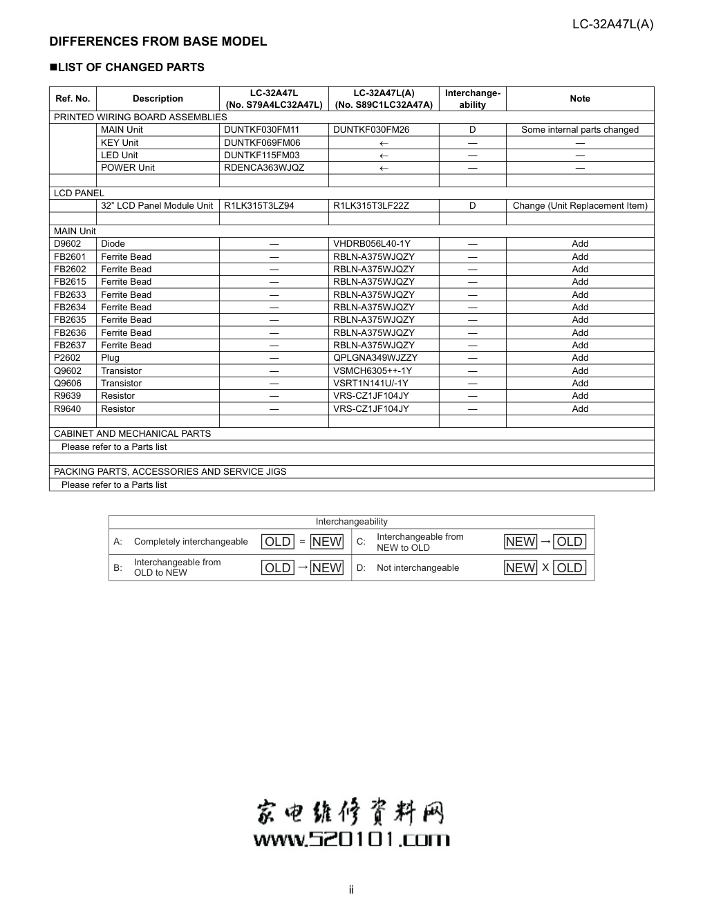
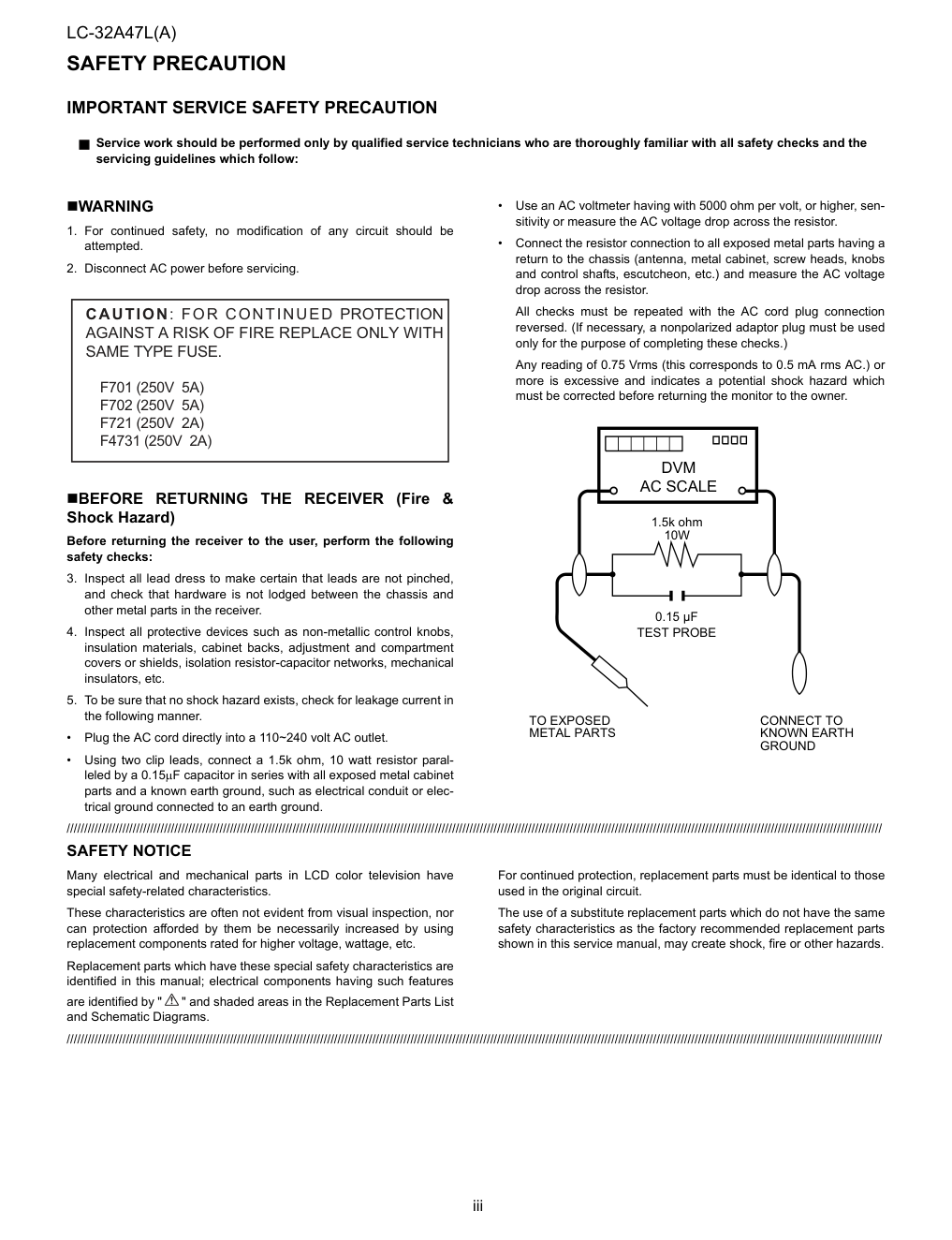
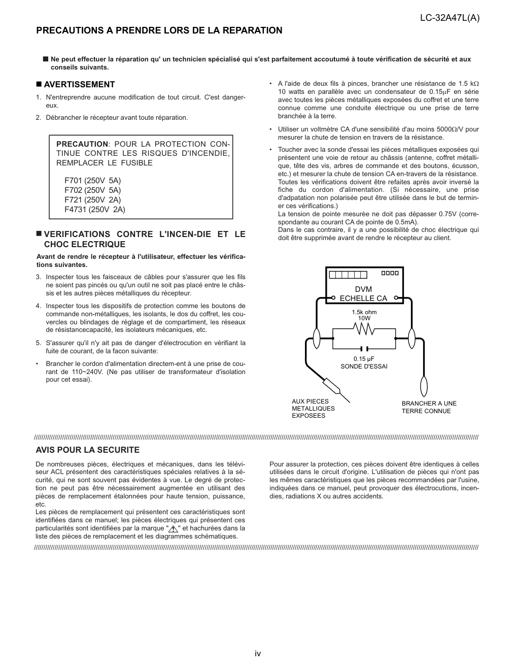
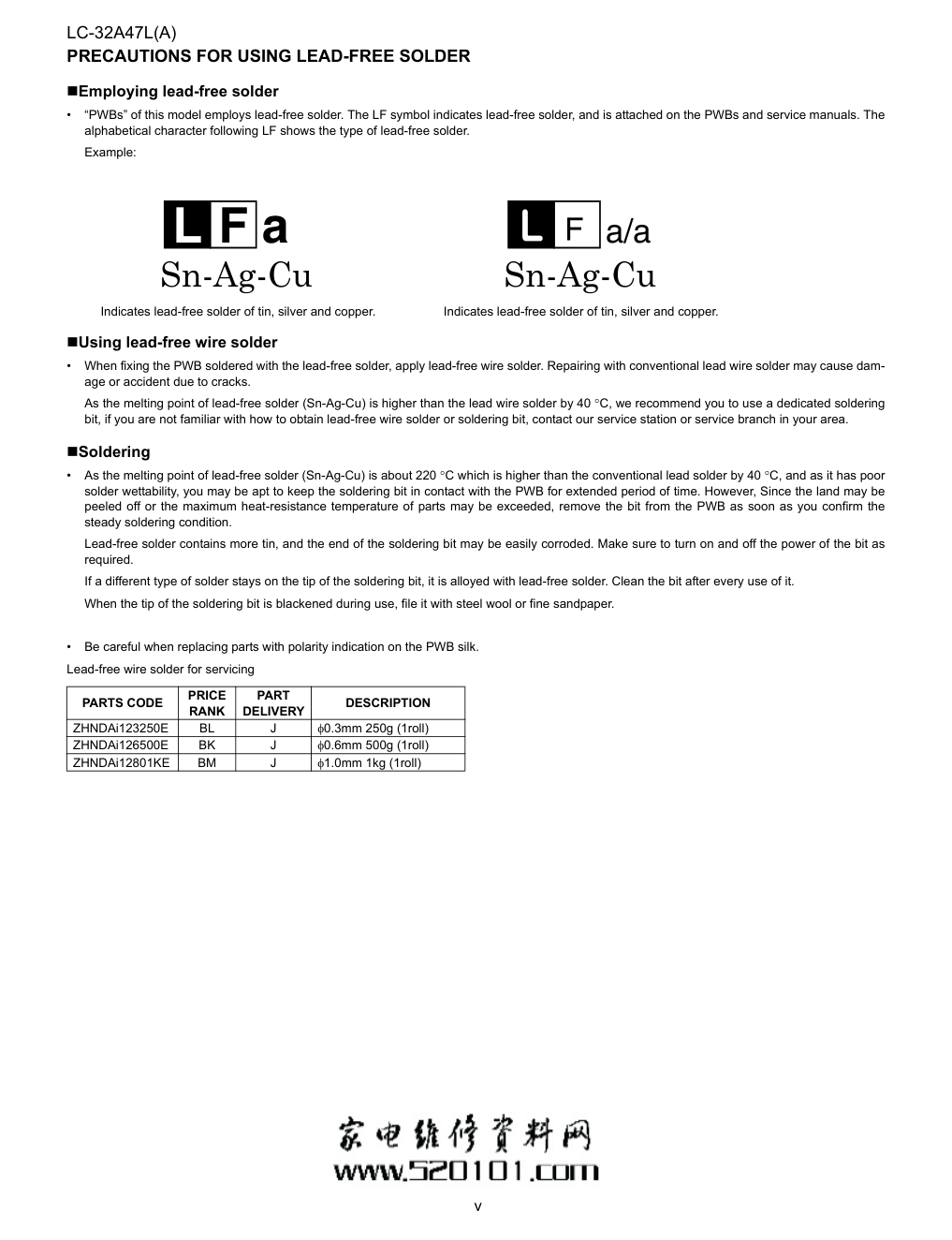
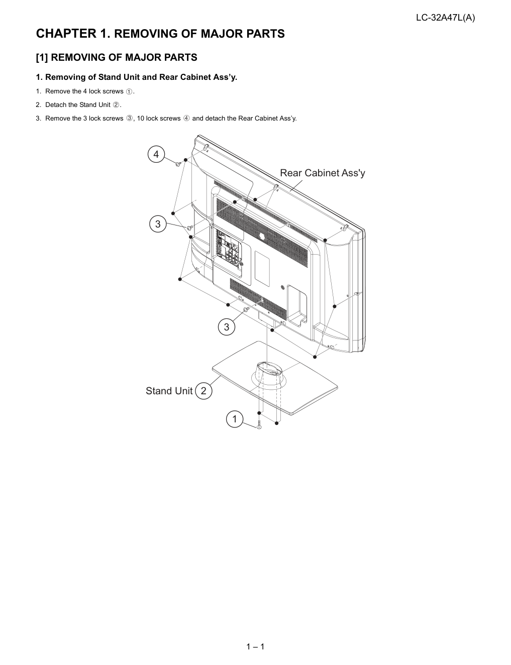
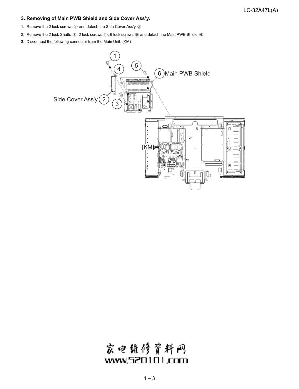
SERVICE MANUAL Parts marked with " " are important for maintaining the safety of the set. Be sure to replace these parts with specified ones for maintaining the safety and performance of the set. This document has been published to be used for after sales service only. The contents are subject to change without notice. OUTLINE AND DIFFERENCES FROM BASE MODEL OUTLINE.................................................................... i DIFFERENCES FROM BASE MODEL..................... ii SAFETY PRECAUTION IMPORTANT SERVICE SAFETY PRECAUTION...........................................................iii PRECAUTIONS A PRENDRE LORS DE LA REPARATION .......................................................... iv PRECAUTIONS FOR USING LEAD-FREE SOLDER ................................................................... v CHAPTER 1. REMOVING OF MAJOR PARTS [1] REMOVING OF MAJOR PARTS ...........................1-1 CHAPTER 2. ADJUSTMENT [1] ADJUSTMENT PROCEDURE...............................2-1 CHAPTER 3. OVERALL WIRING/BLOCK DIAGRAM [1] OVERALL WIRING DIAGRAM ..............................3-1 [2] SYSTEM BLOCK DIAGRAM .................................3-2 CHAPTER 4. PRINTED WIRING BOARD ASSEMBLIES [1] MAIN Unit...............................................................4-1 CHAPTER 5. SCHEMATIC DIAGRAM [1] DESCRIPTION OF SCHEMATIC DIAGRAM.........5-1 [2] MAIN Unit...............................................................5-2 Parts Guide TopPage CONTENTS In the interests of user-safety (Required by safety regulations in some countries) the set should be restored to its original condition and only parts identical to those specified should be used. LCD COLOR TELEVISION No. S89C1LC32A47A LC-32A47L(A) LC-32A47L(A) MODEL OUTLINE This manual has been issued to cover the modifications of some parts in reference to the redesigned LCD panel module of Model LC-32A47L. In this Service Manual, the modifications from Model LC-32A47L (No. S79A4LC32A47L) are focused on. For what is left out herein, please refer back to the Service Manual of the previous model LC-32A47L (No. S79A4LC32A47L). This Service Manual should be referred to as from the July 2009 production units (serial numbers: ****51112 and on). LC-32A47L(A) i LC-32A47L(A) Service Manual OUTLINE AND DIFFERENCES FROM BASE MODEL OUTLINE This manual has been issued to cover the modifications of some parts in reference to the redesigned LCD panel module of Model LC-32A47L. In this Service Manual, the modifications from Model LC-32A47L (No. S79A4LC32A47L) are focused on. For what is left out herein, please refer back to the Service Manual of the previous model LC-32A47L (No. S79A4LC32A47L). This Service Manual should be referred to as from the July 2009 production units (serial numbers: ****51112 and on). Identifying the models with the redesigned LCD panel module • The models with the redesigned LCD panel module have the “ ” marking added at the end of the model number given on the “Model Label”. • The models with the redesigned LCD panel module have the “ ” marking in “No. Label” applied on the packing case. • The models with the redesigned LCD panel module have the “ ” marking in “Back Serial No. Label”. Interchangeability • The previous and redesigned LCD panel modules are not interchangeable with each other. • The redesigned LCD panel module is applicable only on the sets that have been manufactured since July 2009. Model Label SERIAL NO. N'DE SERIE ****51112 LC-32A47L A Back Serial No. Label MODEL NO. LC-32A47L M0015094 ****51112 SERIAL NO. A No. Label of the packing case (Side) MODEL NO. ****51112 SERIAL NO. LC-32A47L M0015094 A No. Label of the packing case (Top) Add Add Add Add Models with the redesigned LCD panel module LC-32A47L(A) ii DIFFERENCES FROM BASE MODEL �LIST OF CHANGED PARTS Ref. No. Description LC-32A47L (No. S79A4LC32A47L) LC-32A47L(A) (No. S89C1LC32A47A) Interchange- ability Note PRINTED WIRING BOARD ASSEMBLIES MAIN Unit DUNTKF030FM11 DUNTKF030FM26 D Some internal parts changed KEY Unit DUNTKF069FM06 ← — — LED Unit DUNTKF115FM03 ← — — POWER Unit RDENCA363WJQZ ← — — LCD PANEL 32” LCD Panel Module Unit R1LK315T3LZ94 R1LK315T3LF22Z D Change (Unit Replacement Item) MAIN Unit D9602 Diode — VHDRB056L40-1Y — Add FB2601 Ferrite Bead — RBLN-A375WJQZY — Add FB2602 Ferrite Bead — RBLN-A375WJQZY — Add FB2615 Ferrite Bead — RBLN-A375WJQZY — Add FB2633 Ferrite Bead — RBLN-A375WJQZY — Add FB2634 Ferrite Bead — RBLN-A375WJQZY — Add FB2635 Ferrite Bead — RBLN-A375WJQZY — Add FB2636 Ferrite Bead — RBLN-A375WJQZY — Add FB2637 Ferrite Bead — RBLN-A375WJQZY — Add P2602 Plug — QPLGNA349WJZZY — Add Q9602 Transistor — VSMCH6305++-1Y — Add Q9606 Transistor — VSRT1N141U/-1Y — Add R9639 Resistor — VRS-CZ1JF104JY — Add R9640 Resistor — VRS-CZ1JF104JY — Add CABINET AND MECHANICAL PARTS Please refer to a Parts list PACKING PARTS, ACCESSORIES AND SERVICE JIGS Please refer to a Parts list Interchangeability Completely interchangeable A: = NEW OLD Interchangeable from OLD to NEW B: � NEW OLD Interchangeable from NEW to OLD C: � NEW OLD Not interchangeable D: X OLD NEW LC-32A47L(A) iii LC-32A47L(A) Service Manual SAFETY PRECAUTION IMPORTANT SERVICE SAFETY PRECAUTION �WARNING 1. For continued safety, no modification of any circuit should be attempted. 2. Disconnect AC power before servicing. �BEFORE RETURNING THE RECEIVER (Fire & Shock Hazard) Before returning the receiver to the user, perform the following safety checks: 3. Inspect all lead dress to make certain that leads are not pinched, and check that hardware is not lodged between the chassis and other metal parts in the receiver. 4. Inspect all protective devices such as non-metallic control knobs, insulation materials, cabinet backs, adjustment and compartment covers or shields, isolation resistor-capacitor networks, mechanical insulators, etc. 5. To be sure that no shock hazard exists, check for leakage current in the following manner. • Plug the AC cord directly into a 110~240 volt AC outlet. • Using two clip leads, connect a 1.5k ohm, 10 watt resistor paral- leled by a 0.15µF capacitor in series with all exposed metal cabinet parts and a known earth ground, such as electrical conduit or elec- trical ground connected to an earth ground. • Use an AC voltmeter having with 5000 ohm per volt, or higher, sen- sitivity or measure the AC voltage drop across the resistor. • Connect the resistor connection to all exposed metal parts having a return to the chassis (antenna, metal cabinet, screw heads, knobs and control shafts, escutcheon, etc.) and measure the AC voltage drop across the resistor. All checks must be repeated with the AC cord plug connection reversed. (If necessary, a nonpolarized adaptor plug must be used only for the purpose of completing these checks.) Any reading of 0.75 Vrms (this corresponds to 0.5 mA rms AC.) or more is excessive and indicates a potential shock hazard which must be corrected before returning the monitor to the owner. /////////////////////////////////////////////////////////////////////////////////////////////////////////////////////////////////////////////////////////////////////////////////////////////////////////////////////////////////////////// SAFETY NOTICE Many electrical and mechanical parts in LCD color television have special safety-related characteristics. These characteristics are often not evident from visual inspection, nor can protection afforded by them be necessarily increased by using replacement components rated for higher voltage, wattage, etc. Replacement parts which have these special safety characteristics are identified in this manual; electrical components having such features are identified by " " and shaded areas in the Replacement Parts List and Schematic Diagrams. For continued protection, replacement parts must be identical to those used in the original circuit. The use of a substitute replacement parts which do not have the same safety characteristics as the factory recommended replacement parts shown in this service manual, may create shock, fire or other hazards. /////////////////////////////////////////////////////////////////////////////////////////////////////////////////////////////////////////////////////////////////////////////////////////////////////////////////////////////////////////// Service work should be performed only by qualified service technicians who are thoroughly familiar with all safety checks and the servicing guidelines which follow: CAUTION: FOR CONTINUED PROTECTION AGAINST A RISK OF FIRE REPLACE ONLY WITH SAME TYPE FUSE. F701 (250V 5A) F702 (250V 5A) F721 (250V 2A) F4731 (250V 2A) DVM AC SCALE 1.5k ohm 10W TO EXPOSED METAL PARTS CONNECT TO KNOWN EARTH GROUND 0.15 µF TEST PROBE LC-32A47L(A) iv PRECAUTIONS A PRENDRE LORS DE LA REPARATION De nombreuses pièces, électriques et mécaniques, dans les télévi- seur ACL présentent des caractéristiques spéciales relatives à la sé- curité, qui ne sont souvent pas évidentes à vue. Le degré de protec- tion ne peut pas être nécessairement augmentée en utilisant des pièces de remplacement étalonnées pour haute tension, puissance, etc. Les pièces de remplacement qui présentent ces caractéristiques sont identifiées dans ce manuel; les pièces électriques qui présentent ces particularités sont identifiées par la marque " " et hachurées dans la liste des pièces de remplacement et les diagrammes schématiques. Pour assurer la protection, ces pièces doivent être identiques à celles utilisées dans le circuit d'origine. L'utilisation de pièces qui n'ont pas les mêmes caractéristiques que les pièces recommandées par l'usine, indiquées dans ce manuel, peut provoquer des électrocutions, incen- dies, radiations X ou autres accidents. AVERTISSEMENT 1. 2. 3. 4. 5. • • • ///////////////////////////////////////////////////////////////////////////////////////////////////////////////////////////////////////////////////////////////////////////////////////////////////////////////////////////////////////////// ///////////////////////////////////////////////////////////////////////////////////////////////////////////////////////////////////////////////////////////////////////////////////////////////////////////////////////////////////////////// Ne peut effectuer la réparation qu' un technicien spécialisé qui s'est parfaitement accoutumé à toute vérification de sécurité et aux conseils suivants. N'entreprendre aucune modification de tout circuit. C'est danger- eux. Débrancher le récepteur avant toute réparation. Inspecter tous les faisceaux de câbles pour s'assurer que les fils ne soient pas pincés ou qu'un outil ne soit pas placé entre le châs- sis et les autres pièces métalliques du récepteur. Inspecter tous les dispositifs de protection comme les boutons de commande non-métalliques, les isolants, le dos du coffret, les cou- vercles ou blindages de réglage et de compartiment, les réseaux de résistancecapacité, les isolateurs mécaniques, etc. S'assurer qu'il n'y ait pas de danger d'électrocution en vérifiant la fuite de courant, de la facon suivante: • Brancher le cordon d'alimentation directem-ent à une prise de cou- rant de 110~240V. (Ne pas utiliser de transformateur d'isolation pour cet essai). A l'aide de deux fils à pinces, brancher une résistance de 1.5 kΩ 10 watts en parallèle avec un condensateur de 0.15µF en série avec toutes les pièces métalliques exposées du coffret et une terre connue comme une conduite électrique ou une prise de terre branchée à la terre. Utiliser un voltmètre CA d'une sensibilité d'au moins 5000Ω/V pour mesurer la chute de tension en travers de la résistance. Toucher avec la sonde d'essai les pièces métalliques exposées qui présentent une voie de retour au châssis (antenne, coffret métalli- que, tête des vis, arbres de commande et des boutons, écusson, etc.) et mesurer la chute de tension CA en-travers de la résistance. Toutes les vérifications doivent être refaites après avoir inversé la fiche du cordon d'alimentation. (Si nécessaire, une prise d'adpatation non polarisée peut être utilisée dans le but de termin- er ces vérifications.) La tension de pointe mesurèe ne doit pas dépasser 0.75V (corre- spondante au courant CA de pointe de 0.5mA). Dans le cas contraire, il y a une possibilité de choc électrique qui doit être supprimée avant de rendre le récepteur au client. PRECAUTION: POUR LA PROTECTION CON- TINUE CONTRE LES RISQUES D'INCENDIE, REMPLACER LE FUSIBLE VERIFICATIONS CONTRE L'INCEN-DIE ET LE CHOC ELECTRIQUE Avant de rendre le récepteur à l'utilisateur, effectuer les vérifica- tions suivantes. DVM ECHELLE CA 1.5k ohm 10W 0.15 µF SONDE D'ESSAI AUX PIECES METALLIQUES EXPOSEES BRANCHER A UNE TERRE CONNUE AVIS POUR LA SECURITE F701 (250V 5A) F702 (250V 5A) F721 (250V 2A) F4731 (250V 2A) LC-32A47L(A) v PRECAUTIONS FOR USING LEAD-FREE SOLDER �Employing lead-free solder • “PWBs” of this model employs lead-free solder. The LF symbol indicates lead-free solder, and is attached on the PWBs and service manuals. The alphabetical character following LF shows the type of lead-free solder. Example: �Using lead-free wire solder • When fixing the PWB soldered with the lead-free solder, apply lead-free wire solder. Repairing with conventional lead wire solder may cause dam- age or accident due to cracks. As the melting point of lead-free solder (Sn-Ag-Cu) is higher than the lead wire solder by 40 °C, we recommend you to use a dedicated soldering bit, if you are not familiar with how to obtain lead-free wire solder or soldering bit, contact our service station or service branch in your area. �Soldering • As the melting point of lead-free solder (Sn-Ag-Cu) is about 220 °C which is higher than the conventional lead solder by 40 °C, and as it has poor solder wettability, you may be apt to keep the soldering bit in contact with the PWB for extended period of time. However, Since the land may be peeled off or the maximum heat-resistance temperature of parts may be exceeded, remove the bit from the PWB as soon as you confirm the steady soldering condition. Lead-free solder contains more tin, and the end of the soldering bit may be easily corroded. Make sure to turn on and off the power of the bit as required. If a different type of solder stays on the tip of the soldering bit, it is alloyed with lead-free solder. Clean the bit after every use of it. When the tip of the soldering bit is blackened during use, file it with steel wool or fine sandpaper. • Be careful when replacing parts with polarity indication on the PWB silk. Lead-free wire solder for servicing Indicates lead-free solder of tin, silver and copper. Indicates lead-free solder of tin, silver and copper. PARTS CODE PRICE RANK PART DELIVERY DESCRIPTION ZHNDAi123250E BL J φ0.3mm 250g (1roll) ZHNDAi126500E BK J φ0.6mm 500g (1roll) ZHNDAi12801KE BM J φ1.0mm 1kg (1roll) LC-32A47L(A) 1 – 1 LC-32A47L(A) Service Manual CHAPTER 1. REMOVING OF MAJOR PARTS [1] REMOVING OF MAJOR PARTS 1. Removing of Stand Unit and Rear Cabinet Ass’y. 1. Remove the 4 lock screws . 2. Detach the Stand Unit . 3. Remove the 3 lock screws , 10 lock screws and detach the Rear Cabinet Ass’y. 2 1 Stand Unit Rear Cabinet Ass'y 3 4 3 LC-32A47L(A) 1 – 2 2. Removing of Speaker L/R, Control Button Ass’y, Front Cabinet Ass’y, LED Unit and KEY Unit. 1. Disconnect the following connectors from the Main Unit. (RA, SP) 2. Detach the Speaker-L and Speaker-R . 3. Detach the LED Unit . 4. Disconnect the following connector from the LED Unit. (RA) 5. Remove the Control Button Ass’y. 6. Detach the KEY Unit from the Control Button and disconnect the connection cord from the KM connector. 7. Remove the 4 lock screws , 6 hooks and detach the Front Cabinet Ass’y. 6 7 7 Control Button Ass'y 4 Control Button 3 LED Unit 1 7 7 2 Speaker-L Speaker-R 5 KEY Unit Front Cabinet Ass'y 6 7 7 [SP] [RA] [SP] [KM] [RA] LC-32A47L(A) 1 – 3 3. Removing of Main PWB Shield and Side Cover Ass’y. 1. Remove the 2 lock screws and detach the Side Cover Ass’y . 2. Remove the 2 lock Shafts , 2 lock screws , 6 lock screws and detach the Main PWB Shield . 3. Disconnect the following connector from the Main Unit. (KM) [KM] 6 1 5 4 3 Main PWB Shield 2 Side Cover Ass'y LC-32A47L(A) 1 – 4 4. Removing of Support Angle and Connectors. 1. Remove the 4 lock screws and detach the Support Angle . 2. Disconnect the following connectors from the Main Unit. (PD, LB1, LP, LW) 3. Disconnect the following connectors from the Power Unit. (PD, LB1, LB2) 4. Disconnect the following connector from the Inverter Unit. (CN101) 5. Disconnect the following connector from the LCD Control Unit. (CN1) [CN1] [CN101] Support Angle (Stand Support) 1 2 POWER Unit INVERTER Unit LCD CONTROL Unit MAIN Unit [LB1] [LB1] [LB2] [PD] [PD] [LP] [LW] POWER Unit MAIN Unit LC-32A47L(A) 1 – 5 5. Removing of POWER Unit, MAIN Unit, Power PWB Angle, Main PWB Angle R/L/M and LCD Fix Angle-T/B. 1. Remove the 6 lock screws and detach the POWER Unit . 2. Remove the 8 lock screws and detach the MAIN Unit . 3. Remove the 10 lock screws and detach the Power PWB Angle , Main PWB Angle R , Main PWB Angle L and Main PWB Angle M . 4. Remove the 6 lock screws and detach the LCD Fix Angle-T and LCD Fix Angle-B . 32" LCD Panel Module Unit 10 11 LCD Fix Angle-T 12 LCD Fix Angle-B 6 Power PWB Angle 8 Main PWB Angle L 2 9 Main PWB Angle M 7 Main PWB Angle R 1 5 3 POWER Unit 4 MAIN Unit LC-32A47L(A) 2 – 1 LC-32A47L(A) Service Manual CHAPTER 2. ADJUSTMENT [1] ADJUSTMENT PROCEDURE 1. Adjustment of white balance Adjustment item Adjustment conditions Adjustment procedure 1 Setting Backlight: +16 (MAX) For detailed adjustment procedure refer to “Kameyama Model Integral WB Adjustment Specifications”. 1) Make the following settings for the set. AV MODE: [DYNAMIC] Backlight: +16 Aging time: Min. 60 minutes 2) Connect the white balance adjustment tool to the set. 3) The cross is displayed by execute command of RS232C and the probe position is set to the center of the screen (please attention the operation manual of CA210). 4) The cross is disappeared by execute command of RS232C. Adjusting the picture by execute command of RS232C 2 Automatic adjustment execution [Adjustment procedure] 1) Using the remote controller, transmit the “monitor adjustment process” code. 2) Set the 2nd point to the specified gradation level, With the strongest color being fixed, turn down the R,G and B settings to their reference levels. 3) Set the 1st point to the specified gradation level. Correct the G setting (388 x 2nd point G setting /875) (rounded off), and make the R and B settings to their reference levels. *Initial R, G and B settings at point 2: Gradation level set at 875 * Initial R and B settings at points 1: Correct the setting same remainder of RGB setting at each point (This is because the adjustment is made to achieve the same remainder of RGB setting/4 at each point). [Adjustment value] As per the “standard set” submitted by Engineering Department. [Adjustment reference] Instrument: [Minolta CA-210] Engineering instrument. Level Reference Adj. spec Ins. spec Point 2 875 X=0.272 ±0.001 ±0.002 y=0.277 Point 1 388 X=0.272 ±0.004 ±0.008 y=0.277 Note Set conditions for inspection AV MODE: [DYNAMIC] (Reset) Aging Time: Min. 60 minutes LC-32A47L(A) 2 – 2 2. Model number ID plug Model numbers are identified by inserting the destination ID plug (QCNCMA275WJQZ) in its specified slot of the destination ID connector SC9003 (QCNCWA715WJQZY). C5 V/LR USB 1 10 1 4 L/R out Analog RGB PC Audio IN 1 41 1 12 1 4 TUNER MAIN Unit 1 6 DDR Position SC9003 HDMI SC9003 LC-32A47L(A) Destination ID connector locations Plug locations ������������������������ ������������������� ���������������� ��������������� 1 15 LC-32A47L(A) 2 – 3 MEMO LC-32A47L(A) 3 – 1 LC-32A47L(A) Service Manual CHAPTER 3. OVERALL WIRING/BLOCK DIAGRAM [1] OVERALL WIRING DIAGRAM A C B D E F G I H 1 2 3 4 5 6 7 8 9 10 11 12 13 14 15 16 17 18 19 20 21 22 32" LCD Panel [KM] 4 1 [RA] LED Unit LCD Cont Unit KEY Unit INV Unit POWER Unit [PD] 12 1 MAIN Unit [RA] 1 10 1 4 [SP] [LW] 41 1 [PD] 12 1 6 1 [LB1] 15 1 [LP] TUNER USB L/R Output Analog RGB HDMI V/ LR PC Audio IN [KM] 4 1 C5 DDR Position QCNW-J170WJQZ QCNW-J171WJQZ QCNW-J834WJPZ QCNW-J173WJQZ QCNW-J174WJQZ 4 1 [LB1] 7 1 1 14 [LB2] CN101 1 14 QCNW-J639WJQZ QCNW-J630WJPZ SC9003 OVERALL WIRING DIAGRAM [LW / LP] 30 1 CN1 LC-32A47L(A) 3 – 2 [2] SYSTEM BLOCK DIAGRAM A C B D E F G I H 1 2 3 4 5 6 7 8 9 10 11 12 13 14 15 16 17 18 19 20 21 22 zz S Video IC8001 RH-IXC677WJQZQ DTV-C5 for WXGA Digital AV decode & Main CPU PROTECT N_CPU_RST IC1301 Audio DAC AK4341ET [PD] P9601(12 pin) [LB1] P2603 (6 pin) Serial FLASH LVDS OUT USB D_IF in I2S I2C_0 RESET UART-A UART-B AGC RGB in H/V HDMIin CVBS S-Video YPbPr I2C RxD,TxD MAIN SIF Thermister KEY1,KEY2,STANDBYPOW PS_ON Von YPbPr OPC_LED,POW_LED_R,POW_LED_G,LED_YOYAKU, ILL_LED OUT1 HDMI 2 IC2002 R8C/2A IXC165WJ Monitor Micom UART BU+3.3V FRAME,R/L,U/D,TEMP[3:0],O/S_SET A9V 5V D3.3V D2.6V D1.2V I2C I2C_SDA_UCOM I2C_SCL_UCOM ERR_PNL I/O I/O I/O I/O THERMO A/D OPC A/D INT0 R/C CVBS L/R AFT INPUT 1 UR13V BackUp Line MAIN Line BU+5V BU+3.3V PM_REQ, CBOOTS I/O N_SRESET I/O P8001 IC2701 SP AMP YDA148QZ UR13V IC8251 DDR2(800) 512Mb*1 P8001 S-Video VCOM_WP LCDC-EN SHIP_EN,PNEL_EN LINE_OUT_L/R SPOUT_L/R Disclete Mute P2602 AMP_MUTE STANDBY A/D AFT N_SRESET HDMI_MUTE RGB_LR RGB/HDMI Audio (Mini Plug) IC1609 TMDS-SW SII9187 In1 In0 In2 +3.3V [SP] P2701 EXT-SP SP IC2004 Gate 7WH126FU I2S LR Audio Out I/O RST_H8FLS_CPLD FLAS_W_CPLD WEITE_BUF CNVss RxD,TxD 25.000MHz X8001 X'tal 50MHz 16MHz Xtal 16MHz N_DBG_RST I2C_SDA/I2S_SCL (100KHz) INPUT 6 INPUT 5 INPUT 4 LR Component RF IN TU1101 Analog/ Digital Tuner D_IF AGC I2C +5V UCOM_RS STB_CPU STB From CPU ROMSEL0 TUN_I2C TUN_SDA_C5/TUN_SCL_C5(100KHz 5V) IC2001 Reset BU+3.3V N_LINE_DAC_RST LINE_MCLK/BCLK/DAT/LRCLK J8001 USB RS-232C No.9 pin RC Passthrough DET_13V,DET_ DETECT DET_T-CON POW IC602 EEPROM BU+3.3V [LW] (41 pin FFC) [LP] P2602 (15 pin) +3.3V +1.8V +1.2V A9V +3.3V SIF Component CVBS/LR INPUT 2 INPUT 3 YPbPr CVBS L/R L/R L/R HDMI 3 Service INPUT 4/5 [RA] P101(7p) R/C OPC POW_LED [RA] P2003(10p) LED Disclete Mute D-SUB RGB HDMI 4 IC8451 Serial FLASH 64Mbit +3.3V From CPU KEY [KM] P2002(4p) [KM] P151 (4p) MODEL_A[1-0] SC9003 PCIN_H/V PCIN_R/G/B In3 IC503 A-SW AUDIO IC9002 SUB-SW HC2G66DP BU+3.3V IC8454 EEPROM 256kbit BU+3.3V VCOM_SDA VCOM_SCL VCOM_SDA VCOM_SCL SYNC_DET The WXGA machine unmounts. P9001 The WXGA machine unmounts. DET_10V POWER LCD PANEL Vbrt P2603 IC2602 DAC M62332FP +3.3V The WXGA machine unmounts. Vbrt PNL_ON From CPU BU5V AC_DET AC_DET Vert. Insert Vert. Insert Vert. Insert Vert. Insert Vert. Insert Vert. Insert Vert. Insert Vert. Insert Vert. Insert Vert. Insert Vert. Insert Horiz. Insert DDC1 not supported Input1 CVBS deleted Connector for Software Writing Connector for Debugging Connector for Model Detect MENU POWER INPUT SELECT Ch-Up/Down Vol-Up/Down Power Circuit SYSTEM BLOCK DIAGRAM CN1 (12 pin) [PD] [LB1] (4 pin) [LW / LP] (30 pin FFC) (14 pin) [LB2] (14 pin) CN101 P2601 LC-32A47L(A) 4 – 1 LC-32A47L(A) Service Manual CHAPTER 4. PRINTED WIRING BOARD ASSEMBLIES [1] MAIN Unit A C B D E F G I H 1 2 3 4 5 6 7 8 9 10 11 12 13 14 15 16 17 18 19 20 21 22 MAIN Unit (Side-A) LC-32A47L(A) 4 – 2 A C B D E F G I H 1 2 3 4 5 6 7 8 9 10 11 12 13 14 15 16 17 18 19 20 21 22 MAIN Unit (Side-A Chip) J8001 D607 D608 LUG1102 C641 Q604 R639 C642 R660 D601 R641 R8004 C8150 R8020 FB8004 R662 VA8001 VA8002 FD2 R661 R659 IC602 FB8001 R8085 R8084 C8138 C8918 IC8003 R658 KOUJO1 C640 R619 FB605 C614 R622 D606 R613 SC601 C639 R617 FB604 C612 D605 R625 R610 C638 FB603 R615 C610 D604 R627 R609 FB607 FB606 D602 R608 R607 C607 C9003 R9002 TH2001 R9001 R611 FB9004 FB9003 D9007 Q9001 R9024 C608 R612 IC9001 D603 R9022 D9002 R9020 D9001 SC9001 R9021 D9005 FB9002FB9001 J506 C533 C525 J505 C526 R557 R558 FB513 FB514 R560 R559 C528 C527 R549 FB512 J504 FB511 FB510 R543 FB506 R544 R542 FB505 R541 R8069 J502 FB509 FB508 FB507 R545 R8060 J503 C630 R2012 TL2041 D502 R2017 FB2005 Q2002 FB2006 FB2014 FB2007 R2075 P2003 FB2008 FB2009 FB2010 FB2011 FB2012 FB2013 TU1101 P2701 LF3 LUG1103 R1101 R1102 C1135 C1102 C1134 C1101 FB1102 R1104 R1106 FB1101 VER1 BAR3 BAR1 C1132 C2730 R1142 C1336 C1108 R1103C1136 R1143 C1131 C2726 C2725 R1117 C1110 L2702 L2701 C2711 C2724 C2717 C2712 R2726 R2725 C2704 R2730 R2731 R2752 C2713 IC2701 Q2704 R2742 C2706 C2705 R2741 C2707 C2723 C2716 C2748 R2717 R2753 R2715 R2754 L2703 L2704 C2727 C2728 C2731 LF1 D503 D504 C631 C632 C536 R578 J508 FB519 FB518 R577 R576 R546 C535 R1343R1339 R1345 R547 C1306 R1310 R1340 Q1311 J507 R548 C1307 R1344 C1309 Q1310 R1342 R1334 C534 R575 R574 D505 FB517 C633 D501 C634 C511 C513 D506 C512 C635 D509 D510 C520 R562 R564 C524 C523 R550 C532 C531 R561 R563 R555 R551 R556 R569 Q508 Q507 R570 C538 IC502 R552 R580 R567 R568 R579 C537 Q509 R581 Q510 FB516 R573 R583 C541 C627 IC503 FB515 R571 R582 SC1604 IC1604 R1602 D1306 D1601 R631R634 R632 R629 R633 R630 C605 C606 R616 Q601 Q602 Q603 FB601 C617 C618 C619 C601 R604 C604 R605 R623 FB602 R603 C603 R606 SC1603 R618 C602 R624 L501 R620 J601 R626 C615 R635 IC1603 IC601 C626 C625 C624 C616 D508 R636 C620 C509 C501 C637 R503 C510 R512 R513 R505 R504 C502 FB501 FB503 FB502 R501 SC1601 J501 LUG1101 IC1601 IC1602 R1667 R1675 SC1602 IC1609 L1601 R1710R1641 L1602 R1642 R1676 C1625 L1603 D1619 R1711 R1646 R1644 L1604 R1645 R1669 C1629 R1657 R1677C1630 R1712 C1626 R1678 C1628 R1661 R1660 R1714 R1715 C1622 R1658 R1611 D1620 R1713 R1680 C1621 R1679 R1718 R1716 R1610 R1651 D1623 D1622 R1652 R1656R1655 R1654 R1653 C1637C1634 R1684 Q1614 IC1613 R1688 R1692 C9628 R9647 R9648 R9649 C9630 D514 LUG1107 IC9606 D513 R9633 D9619 R9631 Q9608 C1126 C1128 R1141 R1134 L1105 C1129 L1107 C1103 C1130 L1104 R1135 C1127 C1125 C8031 C8036 C8054 C8063 C8072 C8081 R1145 R8001 R1133 R1140 L1106 R1144 R8002 C8029 C8032 C8037 C8044 C8064 C8066 C8080 R8058 C8139 C8140 R8024 D611 R8068 R8057 C8137 D610 C8141R8067 R8022 R9007 R9003 C1119 C1116 R1128 R1125 D9618 R8059 Q9609 D8001 IC8001 R8062 R8070 R1304 R1302 Q1301 R9632 R9630 IC8251 C9629 R8010 IC9607 R8013 C8082 R8263 R8251 R8253 R8252 C9631 R8262 R8006 R8008 R8007 R8035 R8061 R8064 R8065 R8474 C8461 C8460 C8462 P9001 P8001 R8475 R1323 C1314 IC8454 Q1304 R1337 D1311 R1336 R1338 R1335 Q1309 R8454 R8451 R8452 R8455 D1313 D1304 R1324 R1322 Q1305 R2601 Q2603 SC9301 R2635 R2602 C2710 L2612 L2610 FB2706 L2605 L2604 LUG1104 C1334 P2601 LUG1105 FD1 L2603 L2608 L2607 L2606 L2609 L2611 L2602 L2601 Q9602 FB9613 Q9606R9639 R9640 C2602 C2601 P2602 IC2603 R2619 R2620 R2612 IC2601 R2611 R2606 R2607 C2608 D9602 TP8013 C2606 R2623 P2603 X8001 R8025 R8030 R8031 C8070 R8012 R8019 D2504 D2506 R2510 FB2518 FB2519 D2505 R2512 R2513 FB2520 Q2502 FB2517 FB2515 FB2516 SG2501 RDA8001 SG2502 SG2503 P2501 SG2504 SG2505 SG2506 SG2507 SG2508 R8088 C8096 C8083 C8088 R8015 TP8009 R8017 C8095 R8087 TP8010 C8919 C8920 R8086 FB8022 Q8002R8082 TP8011 R8083 R2505 LUG1108 Q8001 Q2501 R8081 R8080 D8002 C9634 IC9608 C9632 C9007 C9009 C9002 L9603 D9610 C9001 IC9003 R9016 R9017 C9008 C9006 L9601 D9604 D9614 L9604 L9602 D9609 C9633 P9601 SC9002 D2003 C2010 R2016 C2001 SC9003 IC9609 R2025 C9635 R2015 R2013 IC2004 R2026 R2027 C2009 R9031 R2002 C9004 R9032 LUG1106 R2005 IC9002 P2002 R9033 R9015 R2028 LC-32A47L(A) 4 – 3 A C B D E F G I H 1 2 3 4 5 6 7 8 9 10 11 12 13 14 15 16 17 18 19 20 21 22 MAIN Unit (Side-B) LC-32A47L(A) 4 – 4 A C B D E F G I H 1 2 3 4 5 6 7 8 9 10 11 12 13 14 15 16 17 18 19 20 21 22 MAIN Unit (Side-B Chip) TL1102 TL1108 TL1107 TL1101 TL1110 TL1111 R1107 C1123 C1124 C1122 L1108 R1130 Q1104 D2704 C1133 C2741 TL2701 FB2702 CF1101 D2703 C2745 C2740 TL2702 FB2703 D2702 C2744 TL2703 C2743 D2701 FB2704 C2738 R1119 TL2704 Q1101 C2742 FB2705 TL2016 C2737 TL2028 TL2026 TL2025 TL2024 TL2023 TL2022 TL2021 TL2020 TL2019 TL2018 TL2017 TL515 TL526 TL524 TL521 TL522 TL523 TL527 TL525 TL513 TL511 LF2 TL8068 TL514 TL512 TL533 TL531 TL528 TL530 TL529 TL534 TL532 TL537 TL535 TL541 TL542 TL540 TL536 TL538 TL544 TL539 TL543 BAR2 TL9007 TL9004 TL9010 TL9008 TL9006 TL9009 BAR4 TL614 TL602 TL601 TL616 TL604 TL610 TL607 TL608 TL609 TL615 TL8059 TL8061 TL8062 TL8060 TL618 FD4 TL8066 TL8065 TL8064 TL8063 TL8058 TL617 TL507 TL506 TL504 TL502 TL503 TL505 TL501 R1615 R1618 TL1607 Q1613 R1682 D1610 D1612 C1633 TL1633 TL1629 C1631 IC1612 R1686 D1608 R1690 TL605 TL606 R1606 R1604 TL1603 TL603 D1607 D1616 TL1616 TL613 TL612 R1616 TL611 R1614 D1613 TL1608 TL1614 TL1303 TL1304 TL1302 D1615 D1606 R1619 TL1615 D1611 R1617 TL1611 C1312 R1311 R1374 R1605 R1601 C1310 C1311 TL1602 IC1304 L1301 R1333 Q1312 TL1606 R1703 D511 R572 R655 R643 R644 R8072 C629R600 R654 R656 R599 C628 Q606 R657 Q605 TL545 TL546 TL547 TL519 TL520 TL518 TL548 TL549 TL550 TL551 TL552 C1302 TL553 C1316 TL516 TL517 LUG1111 Q1102 R1118 R1120 C1112 R1121 R1115 R1114 R1113 C1107 R1122 R1110 R1308 R1341 C1303 TL1103 R1314 C1137 C1323 R1372 R1108 R1112 R1116 R1315 R1366 R1111 R1362 R1318 R1146 R1330 R1129 Q1103 R1109 R1361 R1317 R1365 C1113 R1329 C1322 R1357 R1355 C1338 TL1120 TL1121 TL1119 TL1115 TL1116 TL1112 TL1114 C1321 C1328 R1316 R1326 R1328 R1331 C1330 C1325 C1327 R1321 R1325 C1331 TL2639 R2616 IC1305 R1327 TL2628 TL2627 TL2651 R2615 FB2632 TL2646 TL2647 TL2643 TL2603 TL2640 C1329 R1319 FB2608 FB2607 TL2602 TL2645 TL2644 TL2642 TL2641 R1320 FB2629 FB2627 FB2626 FB2624 FB2622 R1354 R1353 C1337 R1359 FB2631 FB2628 FB2630 FB2625 FB2623 FB2621 R1356 R1358 R9305 Q1314 Q1313 R9308 R2603 D9613 R2636 R1360 D9302 D9303 D9304 R9301 C9304 TL9302 IC9301 C9303 C9301 C9302 TL9301 R9319 D9301 Q1306 R8014 Q1307 R8457 D1310 D1314 R1305 R8453 R8041 R8039 R8037 TL8001 TL8010 TL8002 R8043 IC8451 R1303 TL8011 R8044 D1305 D1312 TL8012 TL8003 R8045 TL8013 TL8004 R8036 TL9023 C8451 TL8018 TL8005 R8073 R1307 D9008 D1301 D1303 TL8014 TL8006 TL8455 R8038 TL9022 TL8015 TL8007 TL8456 TL8454 R8075 R8456 R1306 D9006 TL8020 TL8008 C8132 R8040 TL9021 D1302 D1307 TL8016 TL8009 R8078 D9004 TL8019 R8077 R8074 R8079 R8046 TL8017 R8042 R8076 Q8003 C9638 C8252 C8263 TL9618 R8259 R8254 R8071 C8262 C8264 R8264 C8269 R8066 R8257 R8256 R8255 R8261 R8260 R8258 FB8023 C8270 R8265 R8267 C8265 C8257 C8267 C8260 C8255 C8009 C8015 C8077 C8011 R8268 C8254 C8256 C8253 R8266 C8010 C8251 C8258 C8261 C8062 C1301 R1301 FL8019 C1305 C8028 C8266 C8268 C8075 C8087 C8035 C8065 C8259 C8018 C8026 C8076 IC1301 C8043 R8003 C8013 R8005 C8014 C8055 TL8067 C8004 C8027 FL8016 FL8015 C1304 FB8003 C1315 TL8021 C8023 R8048 R8047 FL8021 R8049 C8022 FL8022 R8052 C8091 C8092 FL8020 C8008 C8017 C8007 FB8017 FB8016 C8073 C8021 C8006 C8041 C8103 C8005 C8057 C8067 C8003 C8016 FB8014 C8089 FB8015 C1121 C8058 R8009 R1137 C8040 C8045 R1138 FB8020 C8046 C8134 C1120 FB8013 R8050 C8136 R8055 TL9620 C8133 C8142 R8051 C8135 R8056 C8143 R1371 C1341 R1368 IC1307 R1370 C1342 R1367 IC1306 R2504 Q1619 Q1618 Q1617 D1628 D1627 D1626 D1625 R1707 R1706 R1700 R1701 Q1620 R1702 TL1634 TL1627 C1639 R1697 R1696 R1695 IC1614 R1694 D1624 Q1616 Q1621 Q1622 Q1615 R1699 D1629 D1630 D1621 R1705 R1708 R1709 R1698 R1704 R1717 C1619 C1617 C1614 C1615 C1640 IC1610 D1609 C1616 R1685 C1601 C1613 FB1605 C1638 TL1628 C1618 R1640 Q1610 D1614 D1617 C1620 TL1631 R1693 R1689 R1639 C1635 TL1613 TL1617 R1620 R1621 Q1611 Q1609 R1638 D1618 C1623 TL1609 TL1605 Q1623 R1665 R1663 TL1604 R1603 TL9014 R1607 R9030 R9014 R1687 R1691 R9604 TL1601 TL1632 R1683 IC1611 R1609 TL1610 Q1612 R1608 TL1630 C1632 C1636 FB2001 LUG1109 TL9024 TL2002 TL2005 TL2003 TL2004 FB2002 FB2003 FB2004 TL9020 R9028 R9027 R9029 TL9015 TL9016 C2002 TL9017 R9012 R2021 C2007 FL2001 X2001 R2020 TL9018 R2032 R2034 R2036 IC2001 TL2015 TL9614 R2033 R2030 C9602 C2006 R2011 C2003 TP2002 C9601 R2044 R2008 R8026 TP2001 R2042 R2010 C2004 C2013 IC9601 R2009 R2048 R2047 R2022 C2005 C2012 FB9612 C2014 C2016 R2019 R2003 TL9611 R2007 Q2006 R9005 FB9610 IC2002 R2049 R2046 R9008 R2023 FB9609 TL9612 R2024 TL2001 R9644 R9646 TL9610 C2015 R2001 R2014 Q9607 TL9609 R2004 D9616 FB9608 R2006 R2031 R2018 R9642 R9643 R2041 R9645 IC2007 FB9611 C2024 R9607 R9611 TL9608 R2029 TL9005 FB9607 R9025 R9019 C9612 R9026 TL9607 FB9606 R9013 TL9012 TL9003 TL9011 R9018 R9023 TL9616 TL9606 TL9013 IC9611 FB9605 R9636 C9637 R9641 TL9019 R9637 TL9605 IC9603 D9603 R9617 R9603 R9618 C9614 C9623 TL9604 R9601 Q9601 Q9603 C9613 C9625 TL9603 R9620 R9615 C9605 C9610 IC9604 FB9603 C9627 C9619 FB9602 R9612 TL9617 C9617 TL9602 D9601 R9626 FB9601 R9628 R9624 D9608 TL9601 D9615 C9620 R9621 D9605 FB9604 TL9621 R9602 C9604 C9609 TL9615 Q9605 R9616 C9603 C9611 TL9613 R9614 R9605 IC9602 C9607 C9606 R9613 Q9604 R9609 R9610 R9608 D9606 D9607 D9617 C9608 R9606 R9004R9009 R9006 R9035 R9619 C9616 C9615 C9624 C9626 C2501 R9622 IC9605 C9621 C9618 TL9619 R9627 R9629 R9625 D9611 D9612 C9622 R9623 R2503 IC2501 R2502 R1369 D2501 R2511 C2502 R2501 R1373 TL2503 D2503 IC2502 R2508 R2509 D2502 R2507 C2503 FB8018 C2504 R2506 TL2504 FB8021 C8079FB8019 C8131 TL1625 TL1626 C8112 C8128 C8129 C8078 R8011 C8113 C8123 R8034 C8094 C8001 C8047 FB8002 FB8024 C8124 TL2502 C8110 R8028 C8071 C8111 R8029 FB2514 R8027 C8127 C8109 TL2501 C8118 C8114 C8119 TL2506 C8012 FL8017 R8033 C8120 TL2505 C8121 TL2507 FL8018 C8125 TL2508 C8102 C8126 R8053 TL2509 R8021 R9011 R8018 R8032 R9010 R8023 R8016 TL2672 R2640 FB2619 TL2610 R8063 C2607 C2609 FB2613 R8089 C2603 TL2621 Q2601 R2631 FB2620 TL2605 R2609 R8090 R2608 R2621 TL2609 FB2609 Q2602 R2610 R2605 FB2618 IC2602 D2601 R2639 FB2610 FB2611 TL2670 FB2617 TL2671 FB2616 TL2650 FB2614 TL2649 TL2648 FB2612 FB2602 R2604 TL2673 FB2601 TL2638 FB2615 TL2604 LUG1110 FB2633 TL2606 TL2607 FB2634 TL2608 FB2635 TL2611 FB2636 TL2612 FB2637 TL2613 TL2669 FB2606 FB2605 FB2604 FD3 TL2626 TL2625 TL2623 TL2624 LF5 LC-32A47L(A) 5 – 1 LC-32A47L(A) Service Manual CHAPTER 5. SCHEMATIC DIAGRAM [1] DESCRIPTION OF SCHEMATIC DIAGRAM 1. VOLTAGE MEASUREMENT CONDITION: 1) The voltages at test points are measured on exclusive AC adaptor and the stable supply voltage of AC 110~240V. Signals are fed by a color bar signal generator for servicing purpose and the above voltages are measured with a 20k ohm/V tester. 2. INDICATION OF RESISTOR & CAPACITOR: RESISTOR 1) The unit of resistance "Ω" is omitted. (K=kΩ=1000Ω, M=MΩ). 2) All resistors are ± 5%, unless otherwise noted. (K= ± 10%, F= ± 1%, D= ± 0.5%) 3) All resistors are 1/16W, unless otherwise noted. CAPACITOR 1) All capacitors are µF, unless otherwise noted. (P=pF=µµF). 2) All capacitors are 50V, unless otherwise noted. CAUTION: This circuit diagram is original one, therefore there may be a slight difference from yours. SAFETY NOTES: 1) DISCONNECT THE AC PLUG FROM THE AC OUTLET BEFORE REPLACING PARTS. 2) SEMICONDUCTOR HEAT SINKS SHOULD BE REGARDED AS POTENTIAL SHOCK HAZARDS WHEN THE CHASSIS IS OPERATING. IMPORTANT SAFETY NOTICE: PARTS MARKED WITH " " ( ) ARE IMPORTANT FOR MAINTAINING THE SAFETY OF THE SET. BE SURE TO REPLACE THESE PARTS WITH SPECIFIED ONES FOR MAIN- TAINING THE SAFETY AND PERFORMANCE OF THE SET. AVIS DE SECURITE IMPORTANT: LES PIECES MARQUEES " " ( ) SONT IMPOR- TANTES POUR MAINTENIR LA SECURITE DE L'APPAREIL. NE REMPLACER CES PIEDES QUE PAR DES PIECES DONT LE NUMERO EST SPECIFIE POUR MAINTENIR LA SECURITE ET PROTEGER LE BON FONCTIONNEMENT DE L'APPAREIL. LC-32A47L(A) 5 – 2 [2] MAIN Unit • MAIN Unit-6/13 A C B D E F G I H 1 2 3 4 5 6 7 8 9 10 11 12 13 14 15 16 17 18 19 20 21 22 LV0OUT3M LV0OUT3P LV0CKOP LV0CKOM LV0OUT2M LV0OUT2P LV0OUT1P LV0OUT1M LV0OUT0P LV0OUT0M U_D FRAME TEMP3 O_S_SET TEMP1 L_R VON TEMP2 R2602 22K 1 2 3 4 5 6 7 8 R2601 22K 1 2 3 4 5 6 7 8 ERR_PNL D3.3V I2C_SCL SHIP_EN R2603 22K F FB2608 A375WJQZ FB2607 A375WJQZ FB2606 A375WJQZ FB2605 A375WJQZ FB2604 A375WJQZ *R2621 10K C2606 0.1u CZB PNL_EN ROMSEL0 M62332FP 1 AO1 2 NC 3 NC 4 NC 5 GND 6 SDA 7 SCL 8 Vcc I2C_SDA DET_PNL12V Q2603 KRC404E R2635 10K R2636 100K P2601 WA659WJQZ TO LCDCONT 1 SHIP_EN 2 OS_EN 3 PE 4 TEMP1 5 TEMP2 6 TEMP3 7 ROMSEL0 8 ROMSEL1 9 HV_MODE 10 U/D 11 R/L 12 LVDS_SEL 13 GND 14 TE2+ 15 TE2- 16 TD2+ 17 TD2- 18 TCLK2+ 19 TCLK2- 20 GND 21 TC2+ 22 TC2- 23 TB2+ 24 TB2- 25 TA2+ 26 TA2- 27 GND 28 TE1+ 29 TE1- 30 TD1+ 31 TD1- 32 TCLK1+ 33 TCLK1- 34 GND 35 TC1+ 36 TC1- 37 TB1+ 38 TB1- 39 TA1+ 40 TA1- 41 GND *C2609 0.1u 10V 5V PNL_PWM FB2609 A204WJ DET_SYNC R2639 100K FB2619 A074WJ FB2620 A074WJ FB2621 A074WJ FB2622 A074WJ FB2623 A074WJ FB2624 A074WJ FB2625 A074WJ FB2626 A074WJ FB2627 A074WJ FB2628 A074WJ FB2629 A074WJ FB2630 A074WJ FB2631 A074WJ FB2618 A074WJ *FB2602 A375WJQZ FB2613 A074WJ L2601 FA154WJ 1 2 3 4 L2606 FA154WJ 1 2 3 4 L2607 FA154WJ 1 2 3 4 L2602 FA154WJ 1 2 3 4 L2608 FA154WJ 1 2 3 4 PNL_PWM2 PNL_12V *P2602 NA349WJ TO LCDCONT 1 VCC 2 VCC 3 VCC 4 VCC 5 GND 6 GND 7 GND 8 GND 9 TEST_MODE -> 10 COND_DET -> 11 VCOM_WP -> 12 VCOM_SCL <-> 13 VCOM_SDA <-> 14 LCD_EN -> 15 DET <- P2603 NA340WJ TO INV 1 GND 2 VON 3 OFL1 4 ERR 5 BRT 6 OFL2 *FB2601 A375WJQZ *FB2615 A375WJQZ *FB2633 A375WJQZ *FB2634 A375WJQZ *FB2635 A375WJQZ *FB2636 A375WJQZ *FB2637 A375WJQZ SHIP_EN R2606 0 R2607 0 R2613 0 R2614 0 TO_MAIN8(CPU) TO_MAIN7(UCOM) TO_MAIN8(CPU) TO_MAIN12(CONN) TO_MAIN13(POWER1) (PWBXF030WJ) -> <- -> -> TO_MAIN11(EXBUS) MAIN6 (PANEL) *IC2602 DUNTKF030WE LW LP LB1 MAIN UNIT 6/13 5.0 LC-32A47L(A) 5 – 3 • MAIN Unit-13/13 A C B D E F G I H 1 2 3 4 5 6 7 8 9 10 11 12 13 14 15 16 17 18 19 20 21 22 D3.3V 400mA C9603 0.01u CZB 25V R9609 47K F D3.3V D1.2V 1030mA C9607 1000P CZB C9611 10u 16V KZA510WJPZ D1.8V 120mA R9605 5.6K D3.3V C9604 0.1u CYB 25V R9610 6.8K D1.8V 300mA D3.3V C9609 10u 16V KZA510WJPZ D9606 EXA523WJ 5.6V R9608 10K F D9608 1PS226 1 2 3 D3.3V C9606 10u 16V KZA510WJPZ D3.3V LV5893M 1 BS 2 Vin 3 SW 4 GND 5 FB 6 COMP 7 EN 8 SS R9626 5.6K F 15uH L9602 CIL PA898WJ 1.9A,77m C9619 4700P CZB 25V R9620 4.7K C9617 10u 16V KZA510WJPZ C9623 10u 16V KZA510WJPZ C9625 10u 16V KZA510WJPZ C9614 0.1u CYB 25V R9628 330 R9624 10K F C9627 10u 16V KZA510WJPZ D9609 D1FS4A VHD D9607 MA111G C9616 0.1u CYB 25V C9626 10u 16V KZA510WJPZ C9618 10u 16V KZA510WJPZ D9611 EXA512WJ 4V R9629 4.7K R9622 4.7K D9610 D1FS4A VHD C9615 0.01u CZB 25V LV5893M 1 BS 2 Vin 3 SW 4 GND 5 FB 6 COMP 7 EN 8 SS R9625 10K F 15uH L9603 PA898WJ 1.9A,77m C9621 4700P CZB 25V C9624 10u 16V KZA510WJPZ R9627 27K F D9612 MA111G D9604 D1FH3 C9613 0.01u CZB 25V D3.3V LV5893M 1 BS 2 Vin 3 SW 4 GND 5 FB 6 COMP 7 EN NC 8 SS R9618 39 R9619 39 15uH L9601 PA898WJ 1.9A,77m R9602 39 D3.3V PQ1LAX95 1 Vadj 2 GND 3 On 4 Vin 5 Vout C9612 1u 10V KZA520WJQZ C9622 1000P CZB R9623 4.7 C9608 1000P CZB R9606 4.7 CZ D3.3V *FB9610 A074WJ FB9603 A375WJQZ FB9609 A074WJ FB9601 A375WJQZ FB9607 A375WJQZ FB9606 A375WJQZ P9601 NA181WJ PD To Power Unit 1 UR13V 2 UR13V UR13V 3 4 UR13V 5 GND 6 GND 7 GND 8 GND 9 AC_DET/NC 10 PS_ON 11 BU5V 12 PNL_ON *FB9612 A375WJQZ FB9604 A375WJQZ *FB9608 A074WJ FB9611 A375WJQZ FB9605 A375WJQZ FB9602 A375WJQZ GND_B TCR5SB33 1 VIn 2 GND 3 ON 4 NC 5 Vout C9602 4.7u 6.3V KZA403WJPZ C9601 1u 10V KZA520WJQZ A9V 5V A5V A5V A5V BU3.3V A9V 5V BU3.3V 5V 5V USB 500mA BU5V 5V R9612 4.7K CZ D9603 MA111G VHD D9605 MA111G VHD Q9601 RN4982 1 2 3 4 5 6 R9603 1K CZ C9610 1u 10V KZA520WJQZ C9605 0.01u 25V R9601 10K CZ Q9603 RN4982 1 2 3 4 5 6 PNL_ON SMPOW SMPOWHOLD BU3.3V AC_DET DET_13V UR13V UR13V D9601 MA111G VHD R9615 5.6K CZ R9617 33K CZ PQ1LA185 1 Vadj 2 GND 3 On 4 Vin 5 Vout C9630 1u 10V KZA520WJQZ C9631 1u 10V KZA520WJQZ C9629 0.1u CZB 10V A1.8V 380mA Q9605 KTC3875SG VS D1.2V R9616 3.9K J R9614 10K F R9613 4.7K CZ Q9604 RT1N141U VS 100uH L9604 PA903WJ 0.7A,0.5 C9633 10u 16V KZA510WJPZ A3.3V 180mA PQ1LA335 1 Nr 2 GND 3 On 4 Vin 5 Vout C9632 0.01u CZB R9641 2.2K C9634 4.7u 6.3V KZA403WJPZ A9V 5V A3.3V AC_DET D3.3V D9613 MA111G VHD 5V BU3.3V BU3.3V BU3.3V D9614 MA111G VHD *R9636 27K CZ *R9637 10K CZ F *Q9606 RT1N141U VS *R9639 100K CZ *Q9602 MCH6305 1 2 3 4 5 6 *R9640 100K CZ *D9602 RB056L40 VHD PNL_12V D9615 MA111G VHD *R9645 1K CZ *R9646 0 CZ MM3441JF 1 Vout 2 NC 3 GND 4 NC 5 CE 6 Sub 7 Vin R9630 1 TWF 1/2W R9632 1 TWF 1/2W R9631 1 TWF 1/2W R9633 1 TWF 1/2W *C9628 0.01u CZB 25V 100u 4V C9638 ARC R9607 47K F R9611 4.7K CZ D9619 MA111G D9618 MA111G Q9608 RN2408 22k 47k 1 2 3 Q9609 RN2408 22k 47k 1 2 3 TO MAIN8(CPU) TO MAIN11(EXBUS) TO MAIN10(EPROM) 5.1V 1440mA TO MAIN12(CONN) TO_MAIN9(DDR) TO MAIN5(HDMI_SW1) TO MAIN7(UCOM) A1.8V 220mA (PWBXF030WJ) TO MAIN6(PANEL) 3.32V 700mA TO MAIN3(AMP_IF) TO MAIN4(AMP) TO MAIN2(A_TERM) TO MAIN1(TUNER) TO MAIN8(CPU) D1.8V 380mA D1.26V 680mA TO MAIN3(AMP_IF) TO MAIN14(SP_IF) TO MAIN6(PANEL) IC9602 IC9605 DUNTKF030WE IC9604 IC9603 IC9601 *IC9606 IC9608 IC9607 MAIN13 (POWER) MAIN UNIT 13/13 0.796 0.796 0.796 LC-32A47L(A) 5 – 4 PARTS GUIDE CONTENTS Parts marked with " " are important for maintaining the safety of the set. Be sure to replace these parts with specified ones for maintaining the safety and performance of the set. This document has been published to be used for after sales service only. The contents are subject to change without notice. LC-32A47L(A) No. S89C1LC32A47A LC-32A47L(A) MODEL LCD COLOR TELEVISION Note: The reference numbers on the PWB are arranged in alphabetical order. PartsGuide [1] PRINTED WIRING BOARD ASSEMBLIES [2] LCD PANEL [3] DUNTKF030FM26 (MAIN Unit) [4] CABINET AND MECHANICAL PARTS [5] SUPPLIED ACCESSORIES [6] PACKING PARTS (NOT REPLACEMENT ITEM) [7] SERVICE JIGS (USE FOR SERVICING) LC-32A47L(A) 2 NO. PARTS CODE PRICE RANK NEW MARK PART DELIVERY DESCRIPTION [1] PRINTED WIRING BOARD ASSEMBLIES N DUNTKF030FM26 BX N X MAIN Unit N DUNTKF069FM06 AH N X KEY Unit N DUNTKF115FM03 AM X LED Unit ! N RDENCA363WJQZ BN N X POWER Unit [2] LCD PANEL N R1LK315T3LF22Z CZ N X 32" LCD Panel Module Unit [3] DUNTKF030FM26 (MAIN Unit) D9602 VHDRB056L40-1Y AC J Diode, RB056L-40TE25 FB2601 RBLN-A375WJQZY AA J Ferrite Bead FB2602 RBLN-A375WJQZY AA J Ferrite Bead FB2615 RBLN-A375WJQZY AA J Ferrite Bead FB2633 RBLN-A375WJQZY AA J Ferrite Bead FB2634 RBLN-A375WJQZY AA J Ferrite Bead FB2635 RBLN-A375WJQZY AA J Ferrite Bead FB2636 RBLN-A375WJQZY AA J Ferrite Bead FB2637 RBLN-A375WJQZY AA J Ferrite Bead P2602 QPLGNA349WJZZY AE J Plug Q9602 VSMCH6305++-1Y AE J Transistor, MCH6305-TL-E Q9606 VSRT1N141U/-1Y AB N J Transistor, RT1N141U-T111-1 R9639 VRS-CZ1JF104JY AA J Resistor, 100k 1/16W Metal Oxide R9640 VRS-CZ1JF104JY AA J Resistor, 100k 1/16W Metal Oxide LC-32A47L(A) 3 [4] CABINET AND MECHANICAL PARTS 28 1-6 1-6 33 32 1-7 1-1 1-7 25 7 40 17 41 9 41 41 41 16 41 1-2 1 8 41 15 10 17 35 35 41 5 36 18 41 13 12 14 11 11 41 30 22 41 41 29 31 41 41 24 3-1 3 3-2 41 37 19 26 27 34 4 2-1 2 39 42 6 42 2-2 2-3 2-3 2-2 20 35 16 35 40 LC-32A47L(A) 4 NO. PARTS CODE PRICE RANK NEW MARK PART DELIVERY DESCRIPTION [4] CABINET AND MECHANICAL PARTS 1 CCABAC469WJ31 BG N X Front Cabinet Ass'y 1-1 Not Available - N - Front Cabinet 1-2 Not Available - - LED Decoration 1-6 Not Available - - Spacer, x2 1-7 PSPAHB408WJZZ AC X Spacer, x2 2 CCABBB638WJ01 BG N X Rear Cabinet Ass'y 2-1 Not Available - N - Rear Cabinet 2-2 Not Available - - VESA Angle, x4 2-3 XEBSN30P08000 AA J Screw, x4 3 CCOVAD295WJ03 AL X Side AV Cover Ass'y 3-1 Not Available - - Side Terminal Cover 3-2 Not Available - N - Side Terminal Label 4 GCOVAD297WJ3A AD X Bass Cone Cover 5 GDAI-A548WJ3A AM X Stand Support 6 HINDPD489WJSA AD N X Model Label 7 JBTN-A812WJ3A AF X Control Button 8 LANGKC126WJFW AN X Support Angle 9 LANGKC275WJFW AP N X LCD Fix Angle-T 10 LANGKC276WJFW AR N X LCD Fix Angle-B 11 LANGKC277WJFW AF N X Power PWB Angle, x2 12 LANGKC278WJFW AF N X Main PWB Angle M 13 LANGKC279WJFW AG N X Main PWB Angle L 14 LANGKC280WJFW AG N X Main PWB Angle R 15 LHLDWA143WJKZ AC J Wire Holder 16 LHLDWA151WJKZ AB J Wire Holder, x2 17 LHLDWA175WJUZ AC J Wire Holder, x8 18 LHLDWA176WJUZ AC J Wire Holder 19 NSFTZA284WJFW AC J Shaft, x2 20 TLABK0023TAZZ AA J Bar Code Label 22 PSLDMB577WJFW AN N X Main PWB Shield 24 QCNCMA275WJQZ AC J Model Selector 25 QCNW-J170WJQZ AF N X Connecting Cord (KM) 26 QCNW-J171WJQZ AL N X Connecting Cord (PD) 27 QCNW-J173WJQZ AK N X Connecting Cord (RA) 28 QCNW-J174WJQZ AG N X Connecting Cord (SP) 29 QCNW-J834WJPZ AV N X Connecting Cord (LW) 30 QCNW-J630WJPZ AK N X Connecting Cord (LB2) 31 QCNW-J639WJQZ AF N X Connecting Cord (LB1) 32 RSP-ZA391WJZZ AP N J Speaker-L 33 RSP-ZA392WJZZ AP N J Speaker-R 34 TLABNB037WJZZ AC X Back Serial No. Label 35 XBBS940P05000 AB J Screw, x6 (for Panel) 36 XBPS740P55KS0 AC X Screw, x4 (for Support) 37 XBPS830P06000 AA J Screw, x2 (for HDMI) 39 XEBS940P16000 AB J Screw, x10 (for Cabinet) 40 XEBSN40P10000 AB J Screw, x4 41 XHPS830P06WS0 AA J Screw, x38 42 XHPS830P10WS0 AB J Screw, x3 LC-32A47L(A) 5 [5] SUPPLIED ACCESSORIES NO. PARTS CODE PRICE RANK NEW MARK PART DELIVERY DESCRIPTION [5] SUPPLIED ACCESSORIES X1 RRMCGA667WJSA AN N X Remote Control Unit ! X2 QACCZA070WJPZ AK J AC Cord X3 CDAI-A549WJ02 BC N X Stand Unit X4 CX-BZA329WJ01 AD N X Screw Ass'y X5 TINS-E169WJN1 AE N X Operation Manual (English) X6 TINS-E170WJN1 AE N X Operation Manual (Spanish) X7 Not Available - - "AA" Size Battery X4 X7 X2 X1 X5 X6 X3 Screw Ass'y "AA" size battery LC-32A47L(A) 6 [6] PACKING PARTS (NOT REPLACEMENT ITEM) S1 S5 S3 S4 S5 S9 S9 S2 S5 S6 S8 S7 S5 X1 X5 X6 X4 X7 X2 LC-32A47L(A) 7 NO. PARTS CODE PRICE RANK NEW MARK PART DELIVERY DESCRIPTION [6] PACKING PARTS (NOT REPLACEMENT ITEM) S1 SPAKCF243WJZZ - N - Packing Case S2 SPAKAA373WJZZ - - Cover Sheet S3 SPAKPB045WJZZ - N - Wrapping Paper S4 SPAKPB385WJZZ - N - Mirror Mat Base S5 SPAKXC400WJZZ - N - Packing Add. S6 SSAKA0101GJZZ - - Polyethylene Bag S7 SSAKAA032WJZZ - - Polyethylene Bag S8 SSAKHA051WJZZ - N - Polyethylene Bag S9 TLABKA009WJZZ - - Case No. Label [7] SERVICE JIGS (USE FOR SERVICING) N QCNW-J832WJPZ N J Connecting Cord (L=700mm) N Main - LCD Control Unit (LW) N QCNW-J277WJQZ J Connecting Cord (L=700mm) N Power - Inverter Unit (LB2) SHARP CORPORATION AV Systems Group CS Promotion Center Yaita, Tochigi 329-2193, Japan Aug. 2009 SH. KD COPYRIGHT 2009 BY SHARP CORPORATION ALL RIGHTS RESERVED. No part of this publication may be reproduced, stored in a retrieval system, or transmitted in any form or by any means, electronic, mechanical, photocopying, recording, or otherwise, without prior written permission of the publisher. LC-32A47L(A)
版权声明
1. 本站所有素材,仅限学习交流,仅展示部分内容,如需查看完整内容,请下载原文件。
2. 会员在本站下载的所有素材,只拥有使用权,著作权归原作者所有。
3. 所有素材,未经合法授权,请勿用于商业用途,会员不得以任何形式发布、传播、复制、转售该素材,否则一律封号处理。
4. 如果素材损害你的权益请联系客服QQ:77594475 处理。