先锋PIONEER DVD-D7361电路图
 "先锋PIONEER DVD-D7361电路图-0")
 "先锋PIONEER DVD-D7361电路图-1")
 "先锋PIONEER DVD-D7361电路图-2")
 "先锋PIONEER DVD-D7361电路图-3")
 "先锋PIONEER DVD-D7361电路图-4")
 "先锋PIONEER DVD-D7361电路图-5")
 "先锋PIONEER DVD-D7361电路图-6")
 "先锋PIONEER DVD-D7361电路图-7")
 "先锋PIONEER DVD-D7361电路图-8")
 "先锋PIONEER DVD-D7361电路图-9")
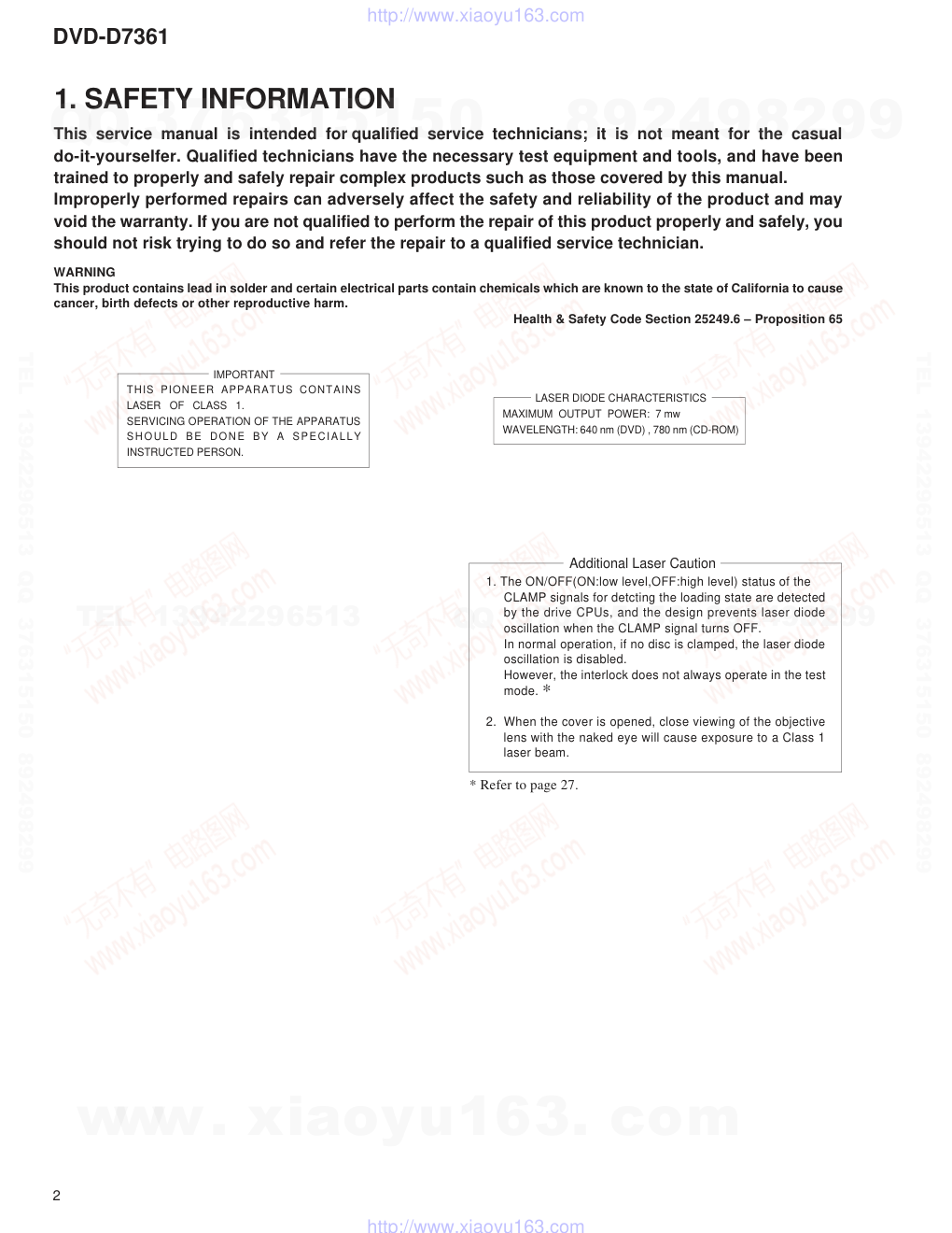
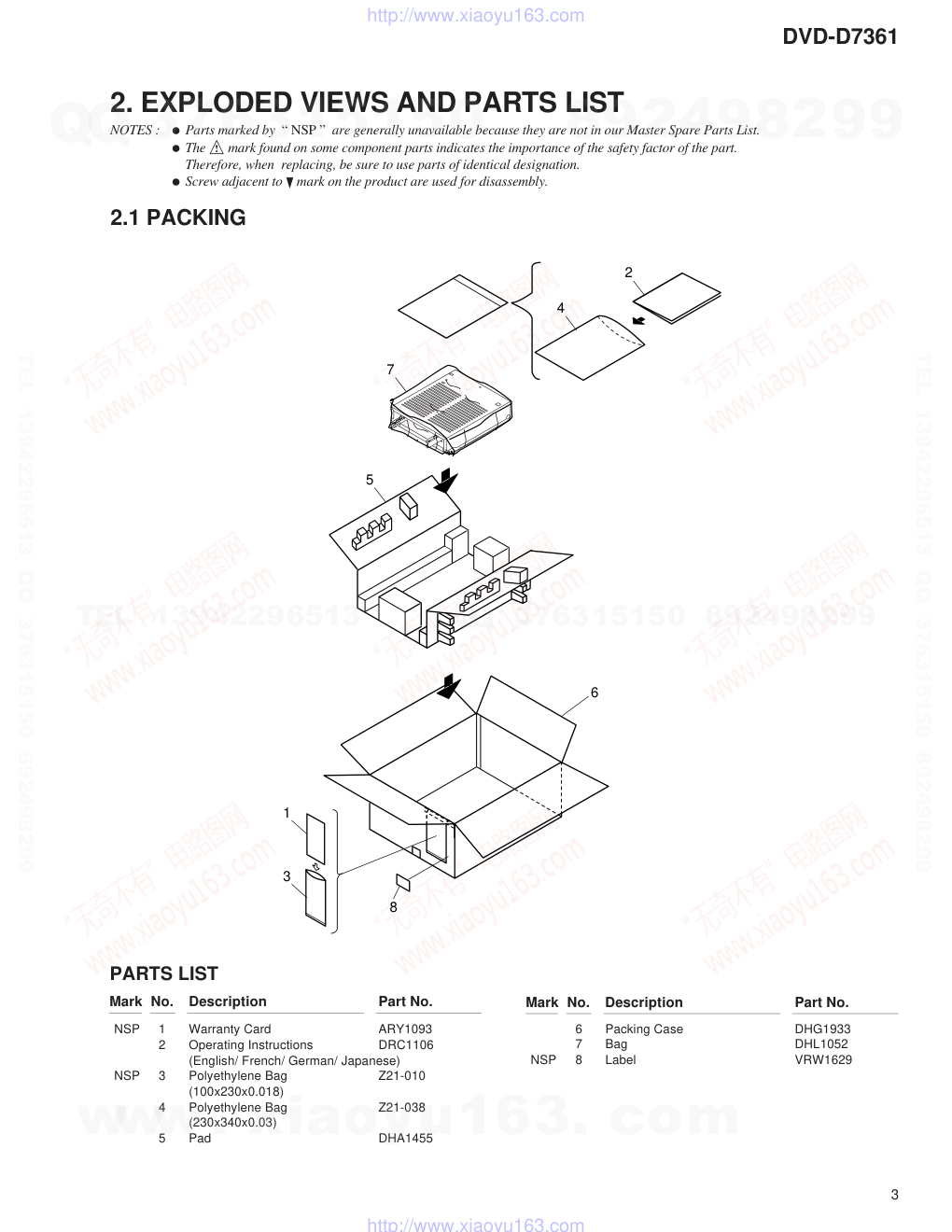
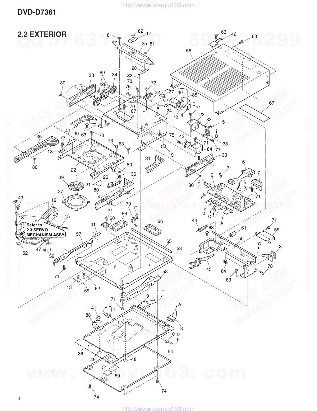
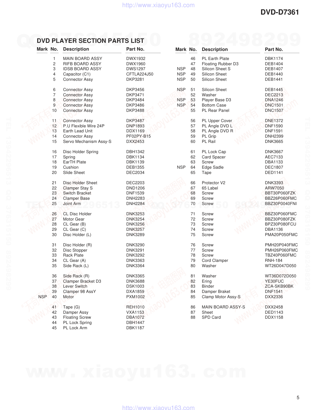
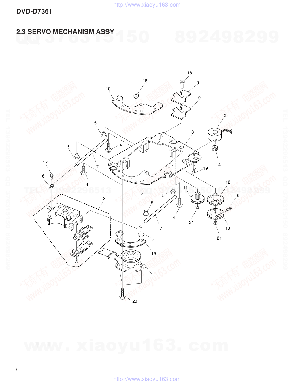
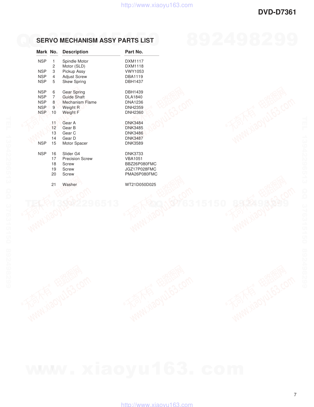
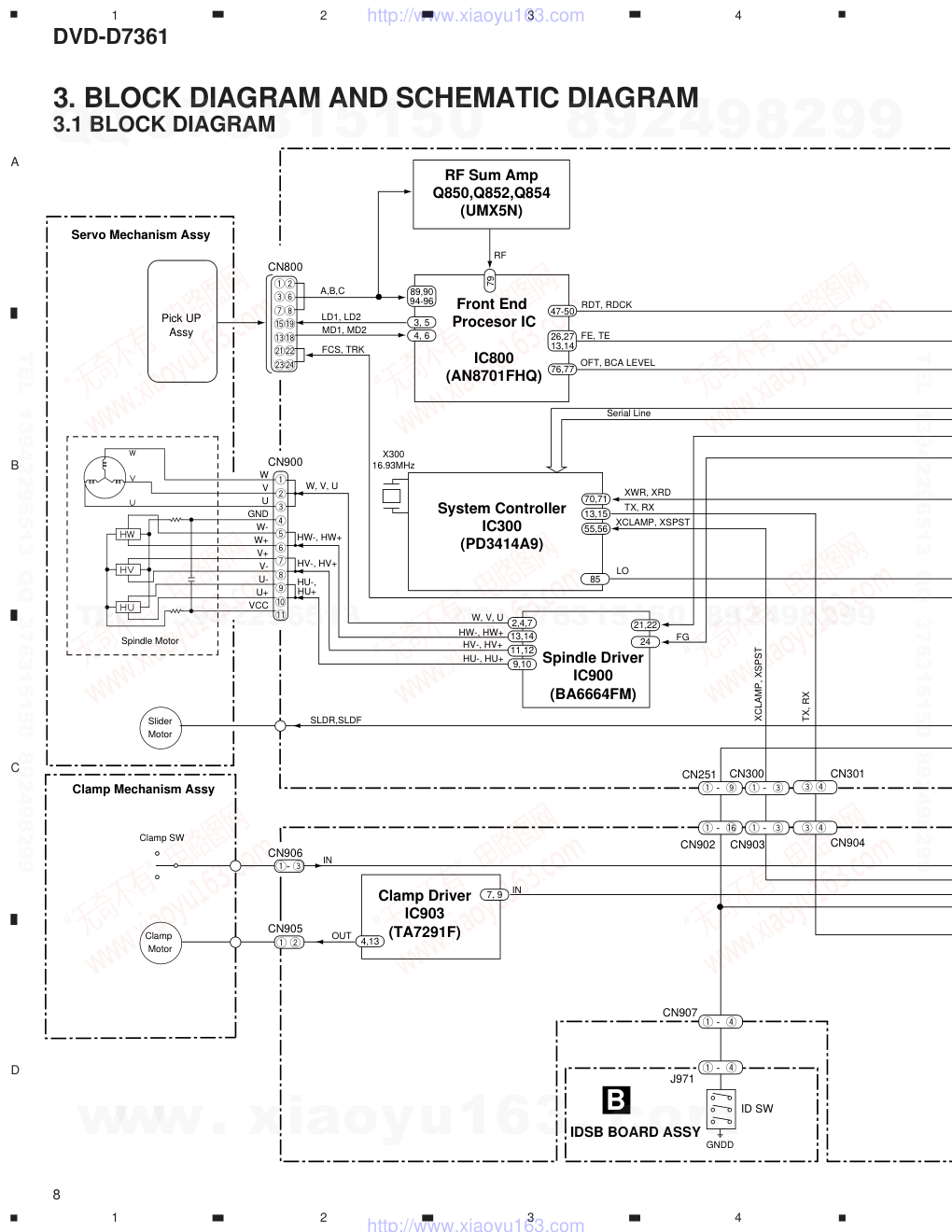
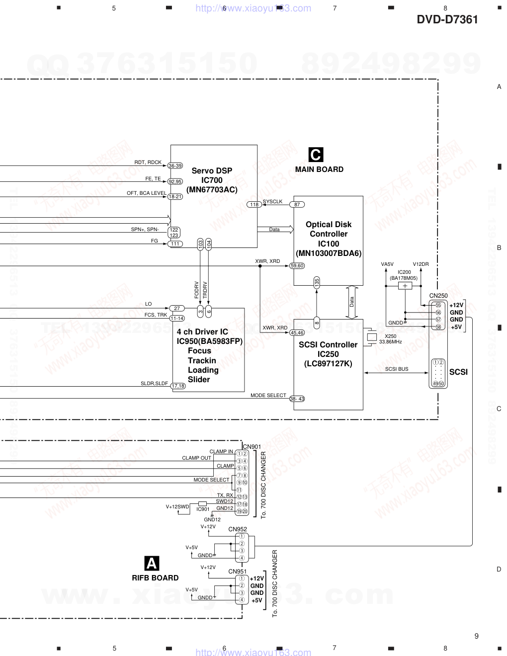
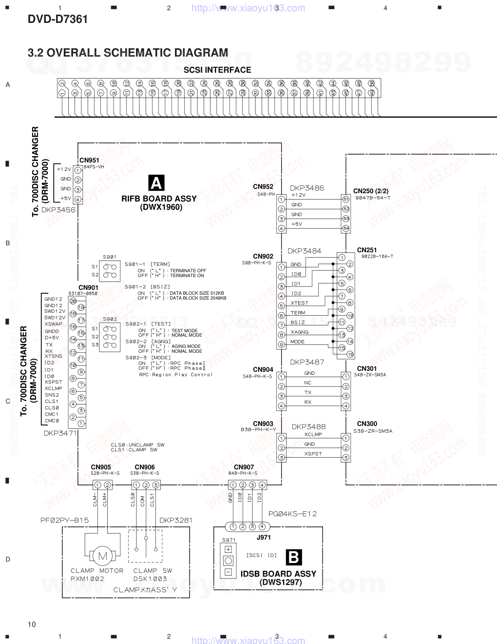
ORDER NO. PIONEER CORPORATION 4-1, Meguro 1-chome, Meguro-ku, Tokyo 153-8654, Japan PIONEER ELECTRONICS SERVICE, INC. P.O. Box 1760, Long Beach, CA 90801-1760, U.S.A. PIONEER ELECTRONIC (EUROPE) N.V. Haven 1087, Keetberglaan 1, 9120 Melsele, Belgium PIONEER ELECTRONICS ASIACENTRE PTE. LTD. 253 Allexandra Road, #04-01, Singapore 159936 � � � � � � � � � �PIONEER CORPORATION 1999 c RRV2174 DVD-D7361 1. SAFETY INFORMATION ....................................... 2 2. EXPLODED VIEWS AND PARTS LIST ................. 3 3. BLOCK DIAGRAM AND SCHEMATIC DIAGRAM 8 4. PCB CONNECTION DIAGRAM ........................... 20 5. PCB PARTS LIST ................................................ 24 6. ADJUSTMENT..................................................... 26 CONTENTS 7. GENERAL INFORMATION .................................. 30 7.1 DIAGNOSIS ................................................... 30 7.1.1 DISASSEMBLY .................................... 30 7.2 PARTS ........................................................... 32 7.2.1 IC .......................................................... 32 8. PANEL FACILITIES AND SPECIFICATIONS....... 33 T – ZZY AUG. 1999 Printed in Japan THIS MANUAL IS APPLICABLE TO THE FOLLOWING MODEL(S) AND TYPE(S). DVD-ROM DRIVE UNIT Remarks Type Model DVD-D7361 Power Requirement ZUCYV/WL O DC Power supply from other system www. xiaoyu163. com QQ 376315150 9 9 2 8 9 4 2 9 8 TEL 13942296513 9 9 2 8 9 4 2 9 8 0 5 1 5 1 3 6 7 3 Q Q TEL 13942296513 QQ 376315150 892498299 TEL 13942296513 QQ 376315150 892498299 http://www.xiaoyu163.com DVD-D7361 2 1. SAFETY INFORMATION This service manual is intended for qualified service technicians; it is not meant for the casual do-it-yourselfer. Qualified technicians have the necessary test equipment and tools, and have been trained to properly and safely repair complex products such as those covered by this manual. Improperly performed repairs can adversely affect the safety and reliability of the product and may void the warranty. If you are not qualified to perform the repair of this product properly and safely, you should not risk trying to do so and refer the repair to a qualified service technician. WARNING This product contains lead in solder and certain electrical parts contain chemicals which are known to the state of California to cause cancer, birth defects or other reproductive harm. Health & Safety Code Section 25249.6 – Proposition 65 IMPORTANT THIS PIONEER APPARATUS CONTAINS LASER OF CLASS 1. SERVICING OPERATION OF THE APPARATUS SHOULD BE DONE BY A SPECIALLY INSTRUCTED PERSON. LASER DIODE CHARACTERISTICS MAXIMUM OUTPUT POWER: 7 mw WAVELENGTH: 640 nm (DVD) , 780 nm (CD-ROM) 1. The ON/OFF(ON:low level,OFF:high level) status of the CLAMP signals for detcting the loading state are detected by the drive CPUs, and the design prevents laser diode oscillation when the CLAMP signal turns OFF. In normal operation, if no disc is clamped, the laser diode oscillation is disabled. However, the interlock does not always operate in the test mode. * 2. When the cover is opened, close viewing of the objective lens with the naked eye will cause exposure to a Class 1 laser beam. Additional Laser Caution * Refer to page 27. www. xiaoyu163. com QQ 376315150 9 9 2 8 9 4 2 9 8 TEL 13942296513 9 9 2 8 9 4 2 9 8 0 5 1 5 1 3 6 7 3 Q Q TEL 13942296513 QQ 376315150 892498299 TEL 13942296513 QQ 376315150 892498299 http://www.xiaoyu163.com DVD-D7361 3 2. EXPLODED VIEWS AND PARTS LIST NOTES : ÷ Parts marked by “ NSP ” are generally unavailable because they are not in our Master Spare Parts List. ÷ The mark found on some component parts indicates the importance of the safety factor of the part. Therefore, when replacing, be sure to use parts of identical designation. ÷ Screw adjacent to ∞ mark on the product are used for disassembly. 2.1 PACKING NSP 1 Warranty Card ARY1093 2 Operating Instructions DRC1106 (English/ French/ German/ Japanese) NSP 3 Polyethylene Bag Z21-010 (100x230x0.018) 4 Polyethylene Bag Z21-038 (230x340x0.03) 5 Pad DHA1455 Mark No. Description Part No. PARTS LIST 6 Packing Case DHG1933 7 Bag DHL1052 NSP 8 Label VRW1629 Mark No. Description Part No. 4 2 1 3 8 6 7 5 www. xiaoyu163. com QQ 376315150 9 9 2 8 9 4 2 9 8 TEL 13942296513 9 9 2 8 9 4 2 9 8 0 5 1 5 1 3 6 7 3 Q Q TEL 13942296513 QQ 376315150 892498299 TEL 13942296513 QQ 376315150 892498299 http://www.xiaoyu163.com DVD-D7361 4 2.2 EXTERIOR G A F C D A B B C D E E F G 27 85 73 73 16 26 31 71 79 44 45 64 63 41 71 57 88 41 69 62 11 71 37 39 63 75 42 72 32 73 40 71 23 77 71 38 71 19 33 83 84 71 59 61 63 55 3 78 66 58 54 48 51 10 65 53 13 71 69 60 66 6 2 71 80 7 5 67 4 14 24 87 56 80 34 29 80 33 30 63 81 25 81 17 63 46 83 28 20 70 73 76 82 63 73 18 41 35 80 36 80 21 43 52 52 13 12 47 47 47 15 22 9 1 86 49 50 8 74 74 80 Refer to 2.3 SERVO MECHANISM ASSY www. xiaoyu163. com QQ 376315150 9 9 2 8 9 4 2 9 8 TEL 13942296513 9 9 2 8 9 4 2 9 8 0 5 1 5 1 3 6 7 3 Q Q TEL 13942296513 QQ 376315150 892498299 TEL 13942296513 QQ 376315150 892498299 http://www.xiaoyu163.com DVD-D7361 5 1 MAIN BOARD ASSY DWX1932 2 RIFB BOARD ASSY DWX1960 3 IDSB BOARD ASSY DWS1297 4 Capacitor (C1) CFTLA224J50 5 Connector Assy DKP3281 6 Connector Assy DKP3456 7 Connector Assy DKP3471 8 Connector Assy DKP3484 9 Connector Assy DKP3486 10 Connector Assy DKP3488 11 Connector Assy DKP3487 12 P.U Flexible Wire 24P DNP1893 13 Earth Lead Unit DDX1169 14 Connector Assy PF02PY-B15 15 Servo Mechanism Assy-S DXX2453 16 Disc Holder Spring DBH1342 17 Spring DBK1134 18 EarTH Plate DBK1139 19 Cushion DEB1355 20 Slide Sheet DEC2034 21 Disc Holder Sheet DEC2203 22 Clamper Stay S DND1206 23 Switch Bracket DNF1539 24 Clamper Base DNH2283 25 Joint Arm DNH2284 26 CL Disc Holder DNK3253 27 Motor Gear DNK3254 28 CL Gear (B) DNK3256 29 CL Gear (C) DNK3257 30 Disc Holder (L) DNK3289 31 Disc Holder (R) DNK3290 32 Disc Stopper DNK3291 33 Rack Plate DNK3292 34 CL Gear (A) DNK3363 35 Side Rack (L) DNK3364 36 Side Rack (R) DNK3365 37 Clamper Bracket D3 DNK3688 38 Lever Switch DSK1003 39 Clamper 98 AssY DXA1859 NSP 40 Motor PXM1002 41 Tape (G) REH1010 42 Damper Assy VXA1153 43 Floating Screw DBA1072 44 PL Lock Spring DBH1447 45 PL Lock Arm DBK1187 Mark No. Description Part No. 46 PL Earth Plate DBK1174 47 Floating Rubber D3 DEB1404 NSP 48 Silicon Sheet S DEB1407 NSP 49 Silicon Sheet DEB1440 NSP 50 Silicon Sheet DEB1441 NSP 51 Silicon Sheet DEB1445 52 Washer DEC2213 NSP 53 Player Base D3 DNA1246 NSP 54 Bottom Case DNC1501 55 PL Rear Panel DNC1507 56 PL Upper Cover DNE1372 57 PL Angle DVD L DNF1590 58 PL Angle DVD R DNF1591 59 PL Grip DNH2399 60 PL Rail DNK3665 61 PL Lock Cap DNK3667 62 Card Spacer AEC7133 63 Screw DBA1133 NSP 64 Edge Sadle DEC1807 65 Tape DED1141 66 Protector V2 DNK3393 67 65 Label ARW7050 68 Screw BBT30P060FZK 69 Screw BBZ26P060FMC 70 Screw BBZ30P0040FNI 71 Screw BBZ30P060FMC 72 Screw BBZ30P080FZK 73 Screw BPZ30P080FCU 74 Screw DBA1136 75 Screw PMA20P050FMC 76 Screw PMH20P040FMC 77 Screw PMH26P060FMC 78 Screw TBZ40P060FMC 79 Cord Clamper RNH-184 80 Washer WT26D047D050 81 Washer WT36D072D050 82 Ering YE30FUC 83 Binder ZCA-SKB90BK 84 Damper Braket DNF1541 85 Clamp Motor Assy-S DXX2336 86 MAIN BOARD ASSY-S DXX2458 87 Sheet DED1143 88 SPD Card DDX1158 Mark No. Description Part No. DVD PLAYER SECTION PARTS LIST www. xiaoyu163. com QQ 376315150 9 9 2 8 9 4 2 9 8 TEL 13942296513 9 9 2 8 9 4 2 9 8 0 5 1 5 1 3 6 7 3 Q Q TEL 13942296513 QQ 376315150 892498299 TEL 13942296513 QQ 376315150 892498299 http://www.xiaoyu163.com DVD-D7361 6 2.3 SERVO MECHANISM ASSY 18 18 8 4 2 14 19 21 7 4 7 15 1 20 4 4 13 21 5 5 12 11 17 5 5 10 16 6 9 9 3 www. xiaoyu163. com QQ 376315150 9 9 2 8 9 4 2 9 8 TEL 13942296513 9 9 2 8 9 4 2 9 8 0 5 1 5 1 3 6 7 3 Q Q TEL 13942296513 QQ 376315150 892498299 TEL 13942296513 QQ 376315150 892498299 http://www.xiaoyu163.com DVD-D7361 7 NSP 1 Spindle Motor DXM1117 2 Motor (SLD) DXM1118 NSP 3 Pickup Assy VWY1053 NSP 4 Adjust Screw DBA1119 NSP 5 Skew Spring DBH1437 NSP 6 Gear Spring DBH1439 NSP 7 Guide Shaft DLA1840 NSP 8 Mechanism Flame DNA1236 NSP 9 Weight R DNH2359 NSP 10 Weight F DNH2360 11 Gear A DNK3484 12 Gear B DNK3485 13 Gear C DNK3486 14 Gear D DNK3487 NSP 15 Motor Spacer DNK3589 NSP 16 Slider G4 DNK3733 17 Precision Screw VBA1051 18 Screw BBZ26P080FMC 19 Screw JGZ17P028FMC 20 Screw PMA26P080FMC 21 Washer WT21D050D025 Mark No. Description Part No. SERVO MECHANISM ASSY PARTS LIST www. xiaoyu163. com QQ 376315150 9 9 2 8 9 4 2 9 8 TEL 13942296513 9 9 2 8 9 4 2 9 8 0 5 1 5 1 3 6 7 3 Q Q TEL 13942296513 QQ 376315150 892498299 TEL 13942296513 QQ 376315150 892498299 http://www.xiaoyu163.com 8 A B C D 1 2 3 4 1 2 3 4 DVD-D7361 Front End Procesor IC IC800 (AN8701FHQ) Spindle Driver IC900 (BA6664FM) Clamp Driver IC903 (TA7291F) System Controller IC300 (PD3414A9) RF Sum Amp Q850,Q852,Q854 (UMX5N) 12� 36� 78� @^� ~%� *(� )_ � CN800 CN900 CN905 A,B,C LD1, LD2 MD1, MD2 FCS, TRK Pick UP Assy 89,90 94-96 3, 5 70,71 55,56 13,15 85 47-50 26,27 13,14 4, 6 1� 2� 3� 4� 5� 6� 7� 8� 9� 0� - W V U GND W- W+ V+ V- U- U+ VCC XWR, XRD RDT, RDCK 76,77 OFT, BCA LEVEL FE, TE W, V, U LO W, V, U HW-, HW+ HW-, HW+ HV-, HV+ HV-, HV+ HU-, HU+ 79 FG HU-, HU+ XCLAMP, XSPST XCLAMP, XSPST TX, RX TX, RX SLDR,SLDF Serial Line Slider Motor Clamp Motor Clamp SW Spindle Motor Servo Mechanism Assy CN251 CN902 X300 16.93MHz B IDSB BOARD ASSY RF 2,4,7 9,10 IN 11,12 13,14 21,22 24 1�- 9 1�- # J971 CN907 ID SW CN300 CN301 CN904 CN903 1�- 3 1�- 3 3�4 3�4 1�2 CN906 1- 3 OUT 4,13 7, 9 IN Clamp Mechanism Assy 1�- 4 1�- 4 GNDD 3. BLOCK DIAGRAM AND SCHEMATIC DIAGRAM 3.1 BLOCK DIAGRAM www. xiaoyu163. com QQ 376315150 9 9 2 8 9 4 2 9 8 TEL 13942296513 9 9 2 8 9 4 2 9 8 0 5 1 5 1 3 6 7 3 Q Q TEL 13942296513 QQ 376315150 892498299 TEL 13942296513 QQ 376315150 892498299 http://www.xiaoyu163.com DVD-D7361 9 A B C D 5 6 7 8 5 6 7 8 Servo DSP IC700 (MN67703AC) Optical Disk Controller IC100 (MN103007BDA6) SCSI Controller IC250 (LC897127K) SCSI +12V GND GND +5V 4 ch Driver IC IC950(BA5983FP) Focus Trackin Loading Slider 11-14 27 59,60 45,46 38- 43 87 118 36-39 92,95 18-21 111 OFT, BCA LEVEL RDT, RDCK FE, TE XWR, XRD XWR, XRD SCSI BUS Data FCS, TRK LO 6 TRDRV 3 104 122 123 103 FODRV 8 135 FG Data SLDR,SLDF MODE SELECT CLAMP MODE SELECT TX, RX SWD12 GND12 SPN+, SPN- SYSCLK 12� � � —±� CN250 IC200 (BA178M05) V12DR VA5V }� |� “� ‘� .... .... X250 33.86MHz C MAIN BOARD A RIFB BOARD GNDD CLAMP OUT 17,18 CN901 CN952 12� 34� 56� 78� 90� -��� =~� $%� ^&� � CLAMP IN V+12V V+12V V+5V V+12SWD IC901 1� 2� 3� 4 GNDD GND12 CN951 V+5V 1� 2� 3� 4 GNDD +12V GND GND +5V To. 700 DISC CHANGER To. 700 DISC CHANGER � www. xiaoyu163. com QQ 376315150 9 9 2 8 9 4 2 9 8 TEL 13942296513 9 9 2 8 9 4 2 9 8 0 5 1 5 1 3 6 7 3 Q Q TEL 13942296513 QQ 376315150 892498299 TEL 13942296513 QQ 376315150 892498299 http://www.xiaoyu163.com 10 A B C D 1 2 3 4 1 2 3 4 DVD-D7361 3.2 OVERALL SCHEMATIC DIAGRAM CN901 CN905 CN906 CN907 CN903 CN904 CN902 CN952 CN250 (2/2) CN251 CN301 CN300 CN951 TEST MODE AGING MODE NOMAL MODE NOMAL MODE DATA BLOCK SIZE 512KB DATA BLOCK SIZE 2048KB TERMINATE OFF TERMINATE ON SCSI INTERFACE A RIFB BOARD ASSY (DWX1960) B IDSB BOARD ASSY (DWS1297) J971 To. 700DISC CHANGER (DRM-7000) To. 700DISC CHANGER (DRM-7000) www. xiaoyu163. com QQ 376315150 9 9 2 8 9 4 2 9 8 TEL 13942296513 9 9 2 8 9 4 2 9 8 0 5 1 5 1 3 6 7 3 Q Q TEL 13942296513 QQ 376315150 892498299 TEL 13942296513 QQ 376315150 892498299 http://www.xiaoyu163.com DVD-D7361 11 A B C D 5 6 7 8 5 6 7 8 Note : When ordering service parts, be sure to refer to "EXPLODED VIEWS and PARTS LIST" or "PCB PARTS LIST". CN250 (1/2) CN800 CN900 (RED) (BLACK) SCSI INTERFACE MAIN BOARD ASSY (1/3- 3/3) (DWX1932) C 1/3- 3/3 www. xiaoyu163. com QQ 376315150 9 9 2 8 9 4 2 9 8 TEL 13942296513 9 9 2 8 9 4 2 9 8 0 5 1 5 1 3 6 7 3 Q Q TEL 13942296513 QQ 376315150 892498299 TEL 13942296513 QQ 376315150 892498299 http://www.xiaoyu163.com 12 A B C D 1 2 3 4 1 2 3 4 DVD-D7361 3.3 RIFB and IDSB BOARD ASSYS A CN906 CN905 CN901 CN951 CN952 CLAMP MECHA ASSY To. 700DISC CHANGER (DRM-7000) To. 700DISC CHANGER (DRM-7000) CN251 C 2/3 YEL CAUTION:FOR CONTINUED PROTECTION AGAINST RISK OF FIRE. REPLACE ONLY WITH SAME TIME NO. ICP-N20, MFD BY ROHM CO., LTD. FOR IC901. www. xiaoyu163. com QQ 376315150 9 9 2 8 9 4 2 9 8 TEL 13942296513 9 9 2 8 9 4 2 9 8 0 5 1 5 1 3 6 7 3 Q Q TEL 13942296513 QQ 376315150 892498299 TEL 13942296513 QQ 376315150 892498299 http://www.xiaoyu163.com DVD-D7361 13 A B C D 5 6 7 8 5 6 7 8B A A RIFB BOARD ASSY (DWX1960) B IDSB BOARD ASSY (DWS1297) CN907 J971 CN902 CN903 CN904 CN251 C 3/3 CN300 C 2/3 CN301 C 2/3 GRN. www. xiaoyu163. com QQ 376315150 9 9 2 8 9 4 2 9 8 TEL 13942296513 9 9 2 8 9 4 2 9 8 0 5 1 5 1 3 6 7 3 Q Q TEL 13942296513 QQ 376315150 892498299 TEL 13942296513 QQ 376315150 892498299 http://www.xiaoyu163.com 14 A B C D 1 2 3 4 1 2 3 4 DVD-D7361 3.4 MAIN BOARD ASSY (1/3) C 1/3 C 1/3 MAIN BOARD ASSY (1/3) (DWX1932) To. PICK UP ASSY To. SLIDER MOTOR CN800 CN900 To. Spindl Motor BA6664FM 1 www. xiaoyu163. com QQ 376315150 9 9 2 8 9 4 2 9 8 TEL 13942296513 9 9 2 8 9 4 2 9 8 0 5 1 5 1 3 6 7 3 Q Q TEL 13942296513 QQ 376315150 892498299 TEL 13942296513 QQ 376315150 892498299 http://www.xiaoyu163.com DVD-D7361 15 A B C D 5 6 7 8 5 6 7 8 C 1/3 CN252 No Conection NO MOUNT D OUT CPU OFTER SOD MOND DIFP DIFN BOD XTRON RESET C 2/3 RF-TP: PLAY MODE (CD) 100mV/div 0.1µsec/div 1 RF-TP: PLAY MODE (DVD) 100mV/div 50nsec/div 1 TE-TP: PLAY MODE (CD) 500mV/div 5msec/div 2 TE-TP: PLAY MODE (DVD) 500mV/div 1msec/div 2 2 No maunt www. xiaoyu163. com QQ 376315150 9 9 2 8 9 4 2 9 8 TEL 13942296513 9 9 2 8 9 4 2 9 8 0 5 1 5 1 3 6 7 3 Q Q TEL 13942296513 QQ 376315150 892498299 TEL 13942296513 QQ 376315150 892498299 http://www.xiaoyu163.com DVD-D7361 16 A B C D 1 2 3 4 1 2 3 4 3.5 MAIN BOARD ASSY (2/3) C 2/3 C 1/3 C 2/3 MAIN BOARD ASSY (2/3) (DWX1932) CN904 A CN301 CN903 A CN300 D OUT CPU RESET SOD OFTR MOND TKCNT DIFP DIFN BOD XTRON No maunt www. xiaoyu163. com QQ 376315150 9 9 2 8 9 4 2 9 8 TEL 13942296513 9 9 2 8 9 4 2 9 8 0 5 1 5 1 3 6 7 3 Q Q TEL 13942296513 QQ 376315150 892498299 TEL 13942296513 QQ 376315150 892498299 http://www.xiaoyu163.com DVD-D7361 17 A B C D 1 2 3 4 1 2 3 4C 2/3 CN952 A CN250 (2/2) INTSPC D OUT RESET ID AD C 3/3 www. xiaoyu163. com QQ 376315150 9 9 2 8 9 4 2 9 8 TEL 13942296513 9 9 2 8 9 4 2 9 8 0 5 1 5 1 3 6 7 3 Q Q TEL 13942296513 QQ 376315150 892498299 TEL 13942296513 QQ 376315150 892498299 http://www.xiaoyu163.com 18 A B C D 1 2 3 4 1 2 3 4 DVD-D7361 3.6 MAIN BOARD ASSY (3/3) C 3/3 C 3/3 MAIN BOARD ASSY (3/3) (DWX1932) INTSPC D OUT RESET ID AD C 2/3 www. xiaoyu163. com QQ 376315150 9 9 2 8 9 4 2 9 8 TEL 13942296513 9 9 2 8 9 4 2 9 8 0 5 1 5 1 3 6 7 3 Q Q TEL 13942296513 QQ 376315150 892498299 TEL 13942296513 QQ 376315150 892498299 http://www.xiaoyu163.com DVD-D7361 19 A B C D 5 6 7 8 5 6 7 8 C 3/3 CN902 A CN251 TEST MODE TERMINATER: ON DATA BLOCK SIZE: 512KB AGNG MODE NORMAL MODE TERMINATER: OFF DATA BLOCK SIZE: 2048KB NORMAL MODE CN250 (1/2) To. SCSI INTER FACE www. xiaoyu163. com QQ 376315150 9 9 2 8 9 4 2 9 8 TEL 13942296513 9 9 2 8 9 4 2 9 8 0 5 1 5 1 3 6 7 3 Q Q TEL 13942296513 QQ 376315150 892498299 TEL 13942296513 QQ 376315150 892498299 http://www.xiaoyu163.com DVD-D7361 20 A B C D 1 2 3 4 1 2 3 4 4.PCB CONNECTION DIAGRAM NOTE FOR PCB DIAGRAMS : 1. Part numbers in PCB diagrams match those in the schematic diagrams. 2. A comparison between the main parts of PCB and schematic diagrams is shown below. 3. The parts mounted on this PCB include all necessary parts for several destinations. For further information for respective destinations, be sure to check with the schematic diagram. 4. View point of PCB diagrams. Symbol In PCB Diagrams Symbol In Schematic Diagrams Part Name B C E D D G G S S B C E B C E D G S B C E B C E B C E Transistor Transistor with resistor Field effect transistor Resistor array 3-terminal regulator Capacitor Connector P.C.Board Chip Part SIDE A SIDE B www. xiaoyu163. com QQ 376315150 9 9 2 8 9 4 2 9 8 TEL 13942296513 9 9 2 8 9 4 2 9 8 0 5 1 5 1 3 6 7 3 Q Q TEL 13942296513 QQ 376315150 892498299 TEL 13942296513 QQ 376315150 892498299 http://www.xiaoyu163.com DVD-D7361 21 A B C D 1 2 3 4 1 2 3 4 SIDE A RIFB BOARD ASSY A RIFB BOARD ASSY A IDSB BOARD ASSY B Q907 Q904 Q908 Q902 Q901 Q906 Q905 IC901 IC903 IC953 IC954 IC955 Q903 Q951 Q952 (DNP1908-A) (DNP1908-A) C CN301 C CN300 C CN250 C CN251 To. Clamp Motor To. 700DISC CHANGER (DRM-7000) To. 700DISC CHANGER (DRM-7000) To. Clamp SW 4.1 RIFB and IDSB BOARD ASSYS A B SIDE B www. xiaoyu163. com QQ 376315150 9 9 2 8 9 4 2 9 8 TEL 13942296513 9 9 2 8 9 4 2 9 8 0 5 1 5 1 3 6 7 3 Q Q TEL 13942296513 QQ 376315150 892498299 TEL 13942296513 QQ 376315150 892498299 http://www.xiaoyu163.com DVD-D7361 22 A B C D 1 2 3 4 1 2 3 4 SIDE A 4.2 MAIN BOARD ASSY MAIN BOARD ASSY C (DNP1880-B) A CN902 A CN952 To. SCSI Inter fase C www. xiaoyu163. com QQ 376315150 9 9 2 8 9 4 2 9 8 TEL 13942296513 9 9 2 8 9 4 2 9 8 0 5 1 5 1 3 6 7 3 Q Q TEL 13942296513 QQ 376315150 892498299 TEL 13942296513 QQ 376315150 892498299 http://www.xiaoyu163.com DVD-D7361 23 A B C D 1 2 3 4 1 2 3 4 SIDE B IC250 IC200 IC100 IC950 IC900 IC300 IC1 Q601 Q802 Q401 Q500 Q852 Q850 Q854 Q602 Q801 IC800 IC700 IC500 IC251 (DNP1880-B) MAIN BOARD ASSY C A CN903 To. Slider Motor A CN904 To. Spindle Motor To. Pick up Assy C www. xiaoyu163. com QQ 376315150 9 9 2 8 9 4 2 9 8 TEL 13942296513 9 9 2 8 9 4 2 9 8 0 5 1 5 1 3 6 7 3 Q Q TEL 13942296513 QQ 376315150 892498299 TEL 13942296513 QQ 376315150 892498299 http://www.xiaoyu163.com DVD-D7361 24 6. PCB PARTS LIST Mark No. Description Part No. Mark No. Description Part No. NOTES : ÷ Parts marked by “ NSP ” are generally unavailable because they are not in our Master Spare Parts List. ÷ The mark found on some component parts indicates the importance of the safety factor of the part. Therefore, when replacing, be sure to use parts of identical designation. ÷ When ordering resistors, first convert resistance values into code form as shown in the following examples. Ex. 1 When there are 2 effective digits (any digit apart from 0), such as 560 ohm and 47k ohm (tolerance is shown by J = 5%, and K = 10%). 560 Ω = 56 × 10 1 = 561 ................................................... RD1/4PU 5 6 1 J 47k Ω = 47 × 10 3 = 473 .................................................. RD1/4PU 4 7 3 J 0.5 Ω = R50 ...................................................................... RN2H  5 0 K 1 Ω = 1R0 ......................................................................... RS1P 1  0 K Ex. 2 When there are 3 effective digits (such as in high precision metal film resistors). 5.62k Ω = 562 × 10 1 = 5621 ........................................... RN1/4PC 5 6 2 1 F LIST OF ASSEMBLIES RDIF BOARD ASSY DWM2099 RIFB BOARD ASSY DWX1960 IDSB BOARD ASSY DWS1297 MAIN BOARD ASSY DWX1932 RIFB BOARD ASSY SEMICONDUCTORS IC953 HIP1013CB IC901 (0.8A /50V) ICP-N20 IC954, IC955 RF1K49157 IC903 TA7291F Q903 2SC2412K Q901, Q902, Q904, Q907, Q908 DTC124EK Q951, Q952 DTC124EK D902–D905, D908–D931 1SS355 D934–D936 1SS355 D906, D907 RB501V-40 D933 SML-210MT D932 SML-210YT D901 UDZS7.5B SWITCHES AND RELAYS S902 DSX-103 S901 DSX1044 CAPACITORS C902 CEJA101M16 C956 CEJA4R7M25 C901, C903, C951, C952 CKSQYB103K50 C954, C955 CKSQYF104Z50 RESISTORS R960, R961 (24mΩ /1W) DCN1119 R907 RD1/2VM4R7J Other Resistors RS1/10S&&& J OTHERS CN907 (CONNECTOR 4P) B4B-PH-K-S (PCB BINDER) DEF1015 CN901 (CONNECTOR 20P) FAP-20-08#2-0BF CN905 (CONNECTOR 2P) S2B-PH-K-S CN906 (CONNECTOR 3P) S3B-PH-K-S CN904 (CONNECTOR 4P) S4B-PH-K-S CN902 (CONNECTORY 9P) S9B-PH-K-S KN901 (EARTH METAL FITTING) VNF1084 IDSB BOARD ASSY SWITCHES AND RELAYS S971 DSX1043 OTHERS (ID SW HOLDER) DEC1805 J971 PG04KS-E12 MAIN BOARD ASSY SEMICONDUCTORS IC800 AN8701FHQ IC200 BA178M05FP IC950 BA5983FP IC900 BA6664FM IC500 BH3541F IC251 BH9598AFP-Y IC250 LC897127K IC1 MM1458AFBE IC100 MN103007BDA6 IC700 MN67703AC IC300 PD3414A9 Q601, Q602 2SA1036K Q801 2SA1037K Q501, Q502 2SC2411K Q500 DTA144EK Q401, Q700, Q800, Q802 DTC124EK Q850, Q852, Q854 UMX5N D500 DA204K D250 RB160L-40 D999 SLP3117E51HS TH999 DCX1033 COILS AND FILTERS L500–L502 QTL1011 CAPACITORS C713, C715, C956, C957 CCSRCH101J50 C703, C820 CCSRCH121J50 C801, C812 CCSRCH181J50 C723 CCSRCH271J50 C959 CCSRCH471J50 A B C www. xiaoyu163. com QQ 376315150 9 9 2 8 9 4 2 9 8 TEL 13942296513 9 9 2 8 9 4 2 9 8 0 5 1 5 1 3 6 7 3 Q Q TEL 13942296513 QQ 376315150 892498299 TEL 13942296513 QQ 376315150 892498299 http://www.xiaoyu163.com DVD-D7361 25 Mark No. Description Part No. C827, C828 CCSRCH561J25 C718 CCSRCH680J50 C719 CCSRCH681J25 C514, C515 CEAL100M16 C3, C511 CEAL101M6R3 C507 CEAL330M10 C265, C504, C505 CEAL470M6R3 C950 CEAT101M16 C202 CEAT221M6R3 C846 CKSQYB224K16 C6 CKSQYB334K16 C1, C807, C809, C825, C845 CKSQYF104Z25 C205, C805 CKSQYF105Z16 C710, C714, C817 CKSRYB102K50 C116, C150, C280, C351–C353 CKSRYB103K50 C704, C711, C826, C844, C880 CKSRYB103K50 C253, C304, C305, C502, C503 CKSRYB104K16 C508–C510, C701, C821, C830 CKSRYB104K16 C834, C835, C850, C958 CKSRYB104K16 C702 CKSRYB122K50 C888 CKSRYB183K25 C712, C848, C849 CKSRYB222K50 C516, C517 CKSRYB272K50 C902 CKSRYB393K16 C829 CKSRYB473K16 C512, C513, C955 CKSRYB682K50 C100–C115, C250–C252 CKSRYF104Z16 C254–C261, C263, C264 CKSRYF104Z16 C300–C303, C500, C501, C506 CKSRYF104Z16 C700, C705–C708, C716, C717 CKSRYF104Z16 C720–C722, C800, C802 CKSRYF104Z16 C813–C815, C818, C819 CKSRYF104Z16 C831–C833, C836, C861, C862 CKSRYF104Z16 C890, C900, C901, C903–C905 CKSRYF104Z16 C951–C954 CKSRYF104Z16 C750 CKSRYF105Z10 C839 (22µF/6.3V) DCH1119 C841 (33µF/6.3V) DCH1120 C860 (2.2µF/10V) VCG1031 RESISTORS R841 (47kΩ) ACN7077 R850 (51Ω) DCN1115 R854 (510Ω) DCN1116 R858 (750Ω) DCN1117 R830–R832 RS1/10S360J R827–R829 RS1/10S680J R807 RS1/16S1202F R913, R916, R917, R980–R982 RS1/16S2002F R900, R901 RS1/4S1R0J Other Resistors RS1/16S&&& J OTHERS CN252 (CONNECTOR 4P) 103672-3A CN251 (CONNECTOR 16P) 9022B-16A CN250 (CONNECTOR 4P) 9047B-54 X101, X300 (16.93MHz) DSS1107 X250 (33.86MHz) DSS1112 CN300 (CONNECTOR 3P) S3B-ZR-SM3A www. xiaoyu163. com QQ 376315150 9 9 2 8 9 4 2 9 8 TEL 13942296513 9 9 2 8 9 4 2 9 8 0 5 1 5 1 3 6 7 3 Q Q TEL 13942296513 QQ 376315150 892498299 TEL 13942296513 QQ 376315150 892498299 http://www.xiaoyu163.com DVD-D7361 26 6. ADJUSTMENT 6.1 PREPARATIONS CD TEST DISC (CDT-304) DVD TEST DISC GGV1018 (JK1) screwdriver (small) screwdriver (medium) Dual-trace oscilloscope (10 : 1 probe) DC Power Supply Test mode Remote Control Unit (RU-V101) 6.1.1 Jigs and Measuring Instruments www. xiaoyu163. com QQ 376315150 9 9 2 8 9 4 2 9 8 TEL 13942296513 9 9 2 8 9 4 2 9 8 0 5 1 5 1 3 6 7 3 Q Q TEL 13942296513 QQ 376315150 892498299 TEL 13942296513 QQ 376315150 892498299 http://www.xiaoyu163.com DVD-D7361 27 6.2 TEST MODE When operating the DVD-ROM directly, it is possible to operate by connecting the RU-V101 to the DVD-ROM with the interface. [ Test mode ] When the test command is used, Pin 1 of S902 on the RIFB BOARD ASSY to ON. Schematic Diagram of the Conversion Jig for Remote Control Operation. CAUTION-Laser radiation when open. DO NOT STARE INTO BEAM. MAIN BOARD ASSY C RIFB BOARD ASSY A 1 1 2 2 3 3 4 Q1 10k 2.2k Q1: DTC124ES or UN4212 3P mini jack From RU-V101 Interface PH type connector (4P) V+5D REMI GNDD GND RF RF-TP POINT Rear REMI V+5V GNDD O P E N S902 1 2 3 1. TEST 2. XAGNG 3. MODE ON TE.ER FE.ER GND TE.ER/FE.ER TP-POINT www. xiaoyu163. com QQ 376315150 9 9 2 8 9 4 2 9 8 TEL 13942296513 9 9 2 8 9 4 2 9 8 0 5 1 5 1 3 6 7 3 Q Q TEL 13942296513 QQ 376315150 892498299 TEL 13942296513 QQ 376315150 892498299 http://www.xiaoyu163.com DVD-D7361 28 Function Table of the Remote Controller (RU-V101) for Service Key Operation Command Description � CD Position [0] + [TIME] {0TM} All servo OFF [1] + [TIME] {1TM} Laser-diode (LD) ON [2] + [TIME] {2TM} Focus Servo ON/OFF [3] + [TIME] {3TM} Spindle ON [4] + [TIME] {4TM} Tracking Servo ON/OFF [5] + [TIME] {5TM} Spindle CLV Servo [6] + [TIME] {6TM} ID Lead [9] + [TIME] {9TM} Disc Seach [1] + [0] + [TIME] {10TM} CD Servo select [1] + [2] + [TIME] {12TM} Focus Position [1] + [3] + [TIME] {13TM} Tracking Balance Adjustment [1] + [5] + [TIME] {15TM} Focus Gain Adustment [1] + [6] + [TIME] {16TM} Tracking Gain Adjustment [STILL/STEP >>] {SF} 1 Track jump : FWD [STILL/STEP <<] {SR} 1 Track jump : REV [*] + [*] + [*] + [MULTI-SPEED +] {***MF} *** Track jump : FWD [*] + [*] + [*] + [MULTI-SPEED -] {***MR} *** Track jump : REV � DVD Position [0] + [TIME] {0TM} All servo OFF [1] + [TIME] {1TM} Laser-diode (LD) ON/OFF [2] + [TIME] {2TM} Focus Servo ON/OFF [3] + [TIME] {3TM} Spindle ON [4] + [TIME] {4TM} Tracking Servo ON/OFF [6] + [TIME] {6TM} ID Lead [9] + [TIME] {9TM} Disc Seach [1] + [1] + [TIME] {11TM} DVD Servo select [1] + [2] + [TIME] {12TM} Focus Position [1] + [3] + [TIME] {13TM} Tracking Balance Adjustment [1] + [4] + [TIME] {14TM} Focus Posision Adustment [1] + [5] + [TIME] {15TM} Focus Gain Adjustment [1] + [6] + [TIME] {16TM} Tracking Gain Adjustment [STILL/STEP >>] {SF} 1 Track jump : FWD [STILL/STEP <<] {SR} 1 Track jump : REV [*] + [*] + [*] + [MULTI-SPEED +] {***MF} *** Track jump : FWD [*] + [*] + [*] + [MULTI-SPEED -] {***MR} *** Track jump : REV ÷ Test Command www. xiaoyu163. com QQ 376315150 9 9 2 8 9 4 2 9 8 TEL 13942296513 9 9 2 8 9 4 2 9 8 0 5 1 5 1 3 6 7 3 Q Q TEL 13942296513 QQ 376315150 892498299 TEL 13942296513 QQ 376315150 892498299 http://www.xiaoyu163.com DVD-D7361 29 6.3 CD AND DVD RF LEVEL CHECK 1 Oscilloscope AC Mode V: 100mV/div H: 50nSec/div START RF-TP POINT Player RF GND GND Probe (10:1) MAIN BOARD ASSY Test mode � TEST DISC PLAY Check CD: CD-T304 DVD: GGV1018 (JK1) 340mVp–p ±40mV 340mVp–p ±40mV CD DVD www. xiaoyu163. com QQ 376315150 9 9 2 8 9 4 2 9 8 TEL 13942296513 9 9 2 8 9 4 2 9 8 0 5 1 5 1 3 6 7 3 Q Q TEL 13942296513 QQ 376315150 892498299 TEL 13942296513 QQ 376315150 892498299 http://www.xiaoyu163.com 30 DVD-D7361 7. GENERAL INFORMATION 7.1 DIAGNOSIS 7.1.1 DISASSEMBLY ×4 The PL Upper Cover is fixed with Claws at the front and with screws at the rear. To remove the PL Upper Cover, proceed as follows. Failure to do so may damage the claws. While pressing the PL lock lever toward RELEASE, slide the PL Upper Cover backward. (It will stop after sliding approx. 1 cm backward.) Claws (both sides) Press and bend the front part of the PL Upper Cover from the left and right sides to unhook the claws, then lift up the cover. (Do NOT try to lift up the cover forcibly with the claws unhooked. This may damage the claws and make it impossible to reattach the cover.) Remove the PL Upper Cover 4 2 1 3 • When reattaching the cover, reverse the above procedures. (Place the cover approx. 1 cm backward and hook the claws, then slide the cover forward.) • Observe the driver unit from the rear to check that the claws are firmly engaged. PL Upper Cover Claw PL Upper Cover screwdriver (small) screwdriver (medium) Jigs Instruments soldering iron www. xiaoyu163. com QQ 376315150 9 9 2 8 9 4 2 9 8 TEL 13942296513 9 9 2 8 9 4 2 9 8 0 5 1 5 1 3 6 7 3 Q Q TEL 13942296513 QQ 376315150 892498299 TEL 13942296513 QQ 376315150 892498299 http://www.xiaoyu163.com 31 DVD-D7361 1 1 5 3 9 3 4 2 MAIN Board assy C To. Slider Motor To. Pick up Assy To. Serveo mecha Assy 7 7 CN800 CN700 SLDF (Red) SLDR (Blk) 8 SIDE B Clamp Mecha Bottom Case RIFB Board Assy Servo Mechanism Assy Remove the Servo Mechanism Assy Caution: Shift the slide switch of the pickup assy to the short side, and short- circuit the section A before removing the flexible cables. Slide Switch 1 Short side Section A www. xiaoyu163. com QQ 376315150 9 9 2 8 9 4 2 9 8 TEL 13942296513 9 9 2 8 9 4 2 9 8 0 5 1 5 1 3 6 7 3 Q Q TEL 13942296513 QQ 376315150 892498299 TEL 13942296513 QQ 376315150 892498299 http://www.xiaoyu163.com 32 DVD-D7361 • The information shown in the list is basic information and may not correspond exactly to that shown in the schematic diagrams. 7.2.1 IC 7.2 PARTS •Pin Function PD3414A9 (MAIN BOARD ASSY : IC300) • System Control IC No. Name I/O Description 1 VCC I V+5 2 SK O - 3 - O - 4 CSS O - 5 TFSEL O ADSC Input selector 6 XFEPRST O FEP Reset pulse (0: Reset, 1: Reset off) 7 XDSCRST O ADSC Reset pulse (0: Reset, 1: Reset off) 8 XAMUTE O Audio mute (0: mute, 1: mute off) 9 BUSY O Busy LED 10 WFLASH I Flash memory Wright enable signal 11 VSS I GND 12 CPUDOUT O FEP/ADSC serial output 13 REMO O Pasonal computer/Remote control serial output 14 CPUDIN I EEP/ADSC serial input 15 REMI I Pasonal computer/Remote control serial input 16 SCK O EEP/ADSC serial clock 17 WFLASH O Flash memory Wright control clock 18 TKS O TE level select 19 DSW0 O - 20 IDCS O - 21 IDSL O - 22 VSS O GND 23 IDMA O - 24 DSW1 O - 25 GSW O OEIC gain selecter (0: Low, 1: Hi) 26 EJECT O - 27 D0 O Data bus I I 34 D1 O 35 Vcc O V+5V 36 A0 I/O Address bus I I I 43 A7 I/O 44 Vss I GND 45 A8 I/O Address bus I I I 54 A17 I/O 55 XCLMP I Changer clamp (0: clamp, 1: no clamp) 56 SPL2 I - 57 Vss I GND No. Name I/O Description 58 WAIT I ODC for wait input 59 XPST O SPDL stop (0: stop, 1: ) 60 STXSP O SPDL driver IC mute control 61 P67 O - 62 XSTBY I - 63 XMRST I Reset input (0: reset 1: reset off) 64 NMI I - 65 Vss I GND 66 EXTAL I Connect the crystal resonator 67 XTAL I (16.9344MHz) 68 Vcc I V+5V 69 P63 I - 70 XRD O lead signal 71 XWR O right signal 72 P66 O - 73 MD0 I 74 MD1 I CPU mode selecter 75 MD2 I 76 Vcc I V+5V 77 Vref I 78 OFTR I FEP of off track signal input (analog) 79 VREFC I VREF level input (analog) 80 DIFP I Pushpull positive signal input (analog) 81 DIFN I Pushpull negative signal input (analog) 82 P74 I - 83 FEMON I - 84 LEDRV O Lens drive 85 LO O - 86 Avss I Analog GND 87 XINT0 I Interrupt/request to ODIC ATAPI 88 XINT1 I Interrupt/request to ODC DECODER 89 CPUIRQ I Interrupt/request to ADSC 90 P83 O - 91 P84 I - 92 Vss I Gnd 93 DI I - 94 MOND I CD for C1 error count input 95 ENC O ADSC CIRC sirial input enable 96 ENS O ADSC serial input enable 97 BR O SPDL driver IC shoote brake 98 XDMUTE O Driver IC mute control 99 FESEN O EEP serial input enable 100 TKCNT I Track pulse input www. xiaoyu163. com QQ 376315150 9 9 2 8 9 4 2 9 8 TEL 13942296513 9 9 2 8 9 4 2 9 8 0 5 1 5 1 3 6 7 3 Q Q TEL 13942296513 QQ 376315150 892498299 TEL 13942296513 QQ 376315150 892498299 http://www.xiaoyu163.com DVD-D7361 33 8. PANEL FACILITIES AND SPECIFICATIONS REAR PANEL [ REARVIEW ] 1 SCSI termination switch This switch is used to turn the drive's internal SCSI termination switch on and off. Note that this switch is set on at the time of shipment. 2 Data block size switch This switch is used to set the data block size. When this switch is turned on the data block size is set to a length of 2048 bytes, and when it is set off the data block size is set to a length of 512 bytes. 3 Termination indicator When the drive is installed in a changer and its power cable has been connected, this indicator lights up if the drive's SCSI termination switch has been turned on. 4 Wiring monitor indicator Meaning of indicator when indicator is lit up: ¶ Indicates that a disc has been inserted into the drive. ¶ This indicator also lights up when the drive is installed in a changer and its power cable has been connected. Meaning of indicator when indicator flashes in 2-second intervals: ¶ This indicator flashes in 2-second intervals when the drive is installed in a changer and its changer interface cable has been connected. Meaning of indicator when indicator flashes in 0.5-second intervals: ¶ This indicator flashes in 0.5-second intervals when the drive in question has been specified as the drive to be swapped during the swapping of drives. 5 Changer interface cable This cable must be connected to the changer-internal changer interface connector. 6 Power cable This cable must be connected to the power inlet located in the changer. 7 Lock lever When a drive is to be removed from the changer, flip the lock lever to the released position and then pull the drive out from the changer. 8 SCSI ID switches These switches are used to set the drive's SCSI ID. Pressing the upper switch causes the displayed SCSI ID to be decremented, and pressing the lower switch conversely causes the SCSI ID to be incremented. Note that SCSI ID is set to '0' at the time of shipment. 9 SCSI interface connector This connector must be connected to the SCSI cable provided with the changer or to an add-on SCSI cable. RELEASE LOCK WIRING MONITOR IND TERM ON / OFF BLOCK SIZE SCSI TERM IND ON SCSI ID BLOCK SIZE 512 byte OFF ON 2048 byte 8 9 1 2 34 5 6 7 NOTE: Be careful not to allow any part of your body to come into contact with connector pins, as doing so may result in faulty connections or damage from static electricity. www. xiaoyu163. com QQ 376315150 9 9 2 8 9 4 2 9 8 TEL 13942296513 9 9 2 8 9 4 2 9 8 0 5 1 5 1 3 6 7 3 Q Q TEL 13942296513 QQ 376315150 892498299 TEL 13942296513 QQ 376315150 892498299 http://www.xiaoyu163.com DVD-D7361 34 [ TOP VIEW ] TOP PANEL 0 0 Function switch This switch is used to check the device before shipment, and its setting should never be changed. RPC (Region Play Control) Set switch ON = Stay in RPC Phase I mode OFF= Start RPC Phase II mode (Never return to Phase I mode after Phase II mode is used) ¶ Set ON at the time of shipping from the plant. ¶ For a DVD Video playback system (computer) for Phase I, please use with Phase I. When the DVD Video playback system (computer) and the drive have different region codes, DVD Video playback is not possible. Set the jumper switch to OFF only when use of a drive corresponding to Phase II has been specified clearly for the DVD Video playback system (computer). The drive will be initialized automatically and will operate in Phase II mode. ON OFF www. xiaoyu163. com QQ 376315150 9 9 2 8 9 4 2 9 8 TEL 13942296513 9 9 2 8 9 4 2 9 8 0 5 1 5 1 3 6 7 3 Q Q TEL 13942296513 QQ 376315150 892498299 TEL 13942296513 QQ 376315150 892498299 http://www.xiaoyu163.com DVD-D7361 35 SPECIFICATIONS [General functions] Disc diameter ..............................................................12 cm Transfer rate (Sustained) DVD-ROM .............................. maximum 8,100 kBytes/sec.* CD-ROM ................................ maximum 4,800 kBytes/sec.* * The data transfer rate may not be output due to disc conditions (scratches, etc.). Access time (Random average) DVD-ROM .................................................................120 ms CD-ROM .....................................................................90 ms Data buffer capacity ............................................512 kBytes [Others] Power supply............................................... DC +12 V, 1.0 A DC +5 V, 1.0 A External dimensions ... 187.2 (W) x 72.4 (H) x 260.7 (D) mm Weight .........................................................................1.8 kg Operation temperature ................................ +5 °C to +35 °C Operation humidity .............. 5 % to 85 % (no condensation) Storage temperature ................................. –40 °C to +60 °C Storage humidity ................. 5 % to 90 % (no condensation) NOTE: Specifications and design subject to possible modifications without notice, due to improvements. www. xiaoyu163. com QQ 376315150 9 9 2 8 9 4 2 9 8 TEL 13942296513 9 9 2 8 9 4 2 9 8 0 5 1 5 1 3 6 7 3 Q Q TEL 13942296513 QQ 376315150 892498299 TEL 13942296513 QQ 376315150 892498299 http://www.xiaoyu163.com
版权声明
1. 本站所有素材,仅限学习交流,仅展示部分内容,如需查看完整内容,请下载原文件。
2. 会员在本站下载的所有素材,只拥有使用权,著作权归原作者所有。
3. 所有素材,未经合法授权,请勿用于商业用途,会员不得以任何形式发布、传播、复制、转售该素材,否则一律封号处理。
4. 如果素材损害你的权益请联系客服QQ:77594475 处理。