先锋PIONEER DEH-P6200UC电路图
 "先锋PIONEER DEH-P6200UC电路图-0")
 "先锋PIONEER DEH-P6200UC电路图-1")
 "先锋PIONEER DEH-P6200UC电路图-2")
 "先锋PIONEER DEH-P6200UC电路图-3")
 "先锋PIONEER DEH-P6200UC电路图-4")
 "先锋PIONEER DEH-P6200UC电路图-5")
 "先锋PIONEER DEH-P6200UC电路图-6")
 "先锋PIONEER DEH-P6200UC电路图-7")
 "先锋PIONEER DEH-P6200UC电路图-8")
 "先锋PIONEER DEH-P6200UC电路图-9")
PIONEER CORPORATION
4-1, Meguro 1-Chome, Meguro-ku, Tokyo 153-8654, Japan
PIONEER ELECTRONICS SERVICE INC.
P.O.Box 1760, Long Beach, CA 90801-1760 U.S.A.
PIONEER EUROPE N.V.
Haven 1087 Keetberglaan 1, 9120 Melsele, Belgium
PIONEER ELECTRONICS ASIACENTRE PTE.LTD.
253 Alexandra Road, #04-01, Singapore 159936
C PIONEER CORPORATION 2000
K-ZZU. FEB. 2000 Printed in Japan
ORDER NO.
CRT2468
MULTI-CD CONTROL HIGH POWER CD PLAYER WITH FM/AM TUNER
DEH-P6200
X1N/UC
Service
Manual
CONTENTS
1. SAFETY INFORMATION ............................................2
2. EXPLODED VIEWS AND PARTS LIST.......................3
3. BLOCK DIAGRAM AND SCHEMATIC DIAGRAM .....8
4. PCB CONNECTION DIAGRAM ................................26
5. ELECTRICAL PARTS LIST ........................................36
6. ADJUSTMENT..........................................................42
7. GENERAL INFORMATION .......................................46
7.1 DIAGNOSIS ........................................................46
7.1.1 TEST MODE..............................................46
7.1.2 DISASSEMBLY .........................................50
7.2 PARTS .................................................................54
7.2.1 IC................................................................54
7.2.2 DISPLAY....................................................60
7.3 OPERATIONAL FLOW CHART...........................61
8. OPERATIONS AND SPECIFICATIONS.....................62
- This service manual should be used together with the following manual(s):
Model No.
Order No.
Mech. Module
Remarks
CX-958
CRT2423
S8.1
CD Mech. Module:Circuit Description, Mech.Description, Disassembly
www. xiaoyu163. com
QQ 376315150
9
9
2
8
9
4
2
9
8
TEL 13942296513
9
9
2
8
9
4
2
9
8
0
5
1
5
1
3
6
7
3
Q
Q
TEL 13942296513 QQ 376315150 892498299
TEL 13942296513 QQ 376315150 892498299
http://www.xiaoyu163.com
2
DEH-P6200
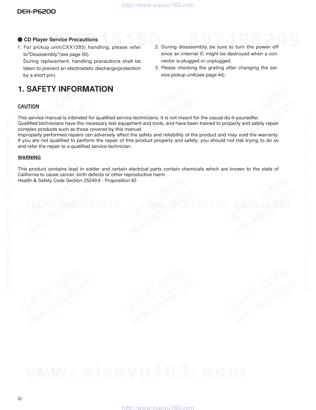
- CD Player Service Precautions
1. For pickup unit(CXX1285) handling, please refer
to"Disassembly"(see page 50).
During replacement, handling precautions shall be
taken to prevent an electrostatic discharge(protection
by a short pin).
2. During disassembly, be sure to turn the power off
since an internal IC might be destroyed when a con-
nector is plugged or unplugged.
3. Please checking the grating after changing the ser-
vice pickup unit(see page 44).
CAUTION
This service manual is intended for qualified service technicians; it is not meant for the casual do-it-yourselfer.
Qualified technicians have the necessary test equipment and tools, and have been trained to properly and safely repair
complex products such as those covered by this manual.
Improperly performed repairs can adversely affect the safety and reliability of the product and may void the warranty.
If you are not qualified to perform the repair of this product properly and safely; you should not risk trying to do so
and refer the repair to a qualified service technician.
WARNING
This product contains lead in solder and certain electrical parts contain chemicals which are known to the state of
California to cause cancer, birth defects or other reproductive harm.
Health & Safety Code Section 25249.6 - Proposition 65
1. SAFETY INFORMATION
www. xiaoyu163. com
QQ 376315150
9
9
2
8
9
4
2
9
8
TEL 13942296513
9
9
2
8
9
4
2
9
8
0
5
1
5
1
3
6
7
3
Q
Q
TEL 13942296513 QQ 376315150 892498299
TEL 13942296513 QQ 376315150 892498299
http://www.xiaoyu163.com
3
DEH-P6200
1 Cord Assy
CDE6242
*
2 Accessory Assy
CEA2395
3 Spring
CBH1650
*
4 Screw Assy
CEA2396
5 Screw
CBA1002
*
6 Polyethylene Bag
CEG-127
7 Screw
CRZ50P090FMC
8 Screw
TRZ50P080FMC
*
9 Polyethylene Bag
CEG-158
10 Handle
CNC5395
11 Bush
CNV3930
12 Polyethylene Bag
CEG1173
13 Battery
CEX1030
14 Carton
CHG3997
15 Contain Box
CHL3997
16 Protector
CHP2251
17 Protector
CHP2252
18 Remote Control Unit
CXB4285
19 Case Assy
CXB3520
20-1 Polyethylene Bag
CEG1116
20-2 Owner’s Manual
CRD3152
(English, French)
20-3 Installation Manual
CRD3153
(English, French)
Mark No. Description
Part No.
Mark No. Description
Part No.
- PACKING SECTION PARTS LIST
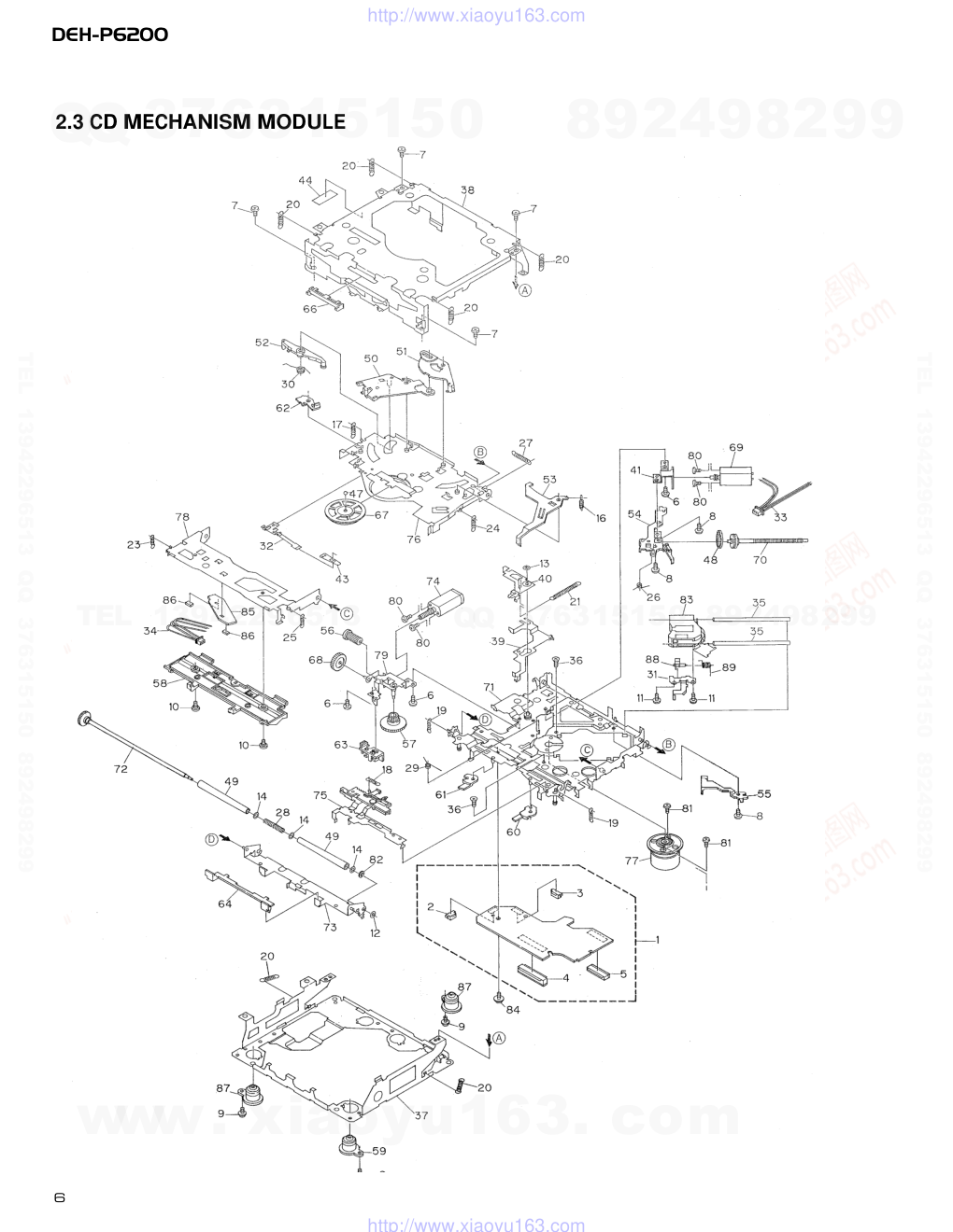
NOTE:
- Parts marked by “*” are generally unavailable because they are not in our Master Spare Parts List.
- Screws adjacent to ∇ mark on the product are used for disassembly.
2. EXPLODED VIEWS AND PARTS LIST
2.1 PACKING
20
19
15
12
16
17
4
7
11
3
10
9
8
6
5
2
14
1
13
18
www. xiaoyu163. com
QQ 376315150
9
9
2
8
9
4
2
9
8
TEL 13942296513
9
9
2
8
9
4
2
9
8
0
5
1
5
1
3
6
7
3
Q
Q
TEL 13942296513 QQ 376315150 892498299
TEL 13942296513 QQ 376315150 892498299
http://www.xiaoyu163.com
4
DEH-P6200
A
A
B
C
B
C
11
95
1717
6
3
71
71
71
71
3
7
3
3
1
21
36
19
31
94
22
24
27
25
29
26
23
33
96
4
4
20
34
96
20
84
87
86
91
88
66
76
75
16
93
77
70
85
90
83
69
53
51
42
61
44
58
5946
54
49
44
55
43
69
69
48
68
60
52
44
44
56
45
62
57
67
44
47
64
65
63
50
2
2
41
4
5
15
18
38
37
12
13
14
14
32
35
28
30
9
10
82
80
8
5
72
92
55
78
97
81
73
74
79
39
40
2.2 EXTERIOR
www. xiaoyu163. com
QQ 376315150
9
9
2
8
9
4
2
9
8
TEL 13942296513
9
9
2
8
9
4
2
9
8
0
5
1
5
1
3
6
7
3
Q
Q
TEL 13942296513 QQ 376315150 892498299
TEL 13942296513 QQ 376315150 892498299
http://www.xiaoyu163.com
DEH-P6200
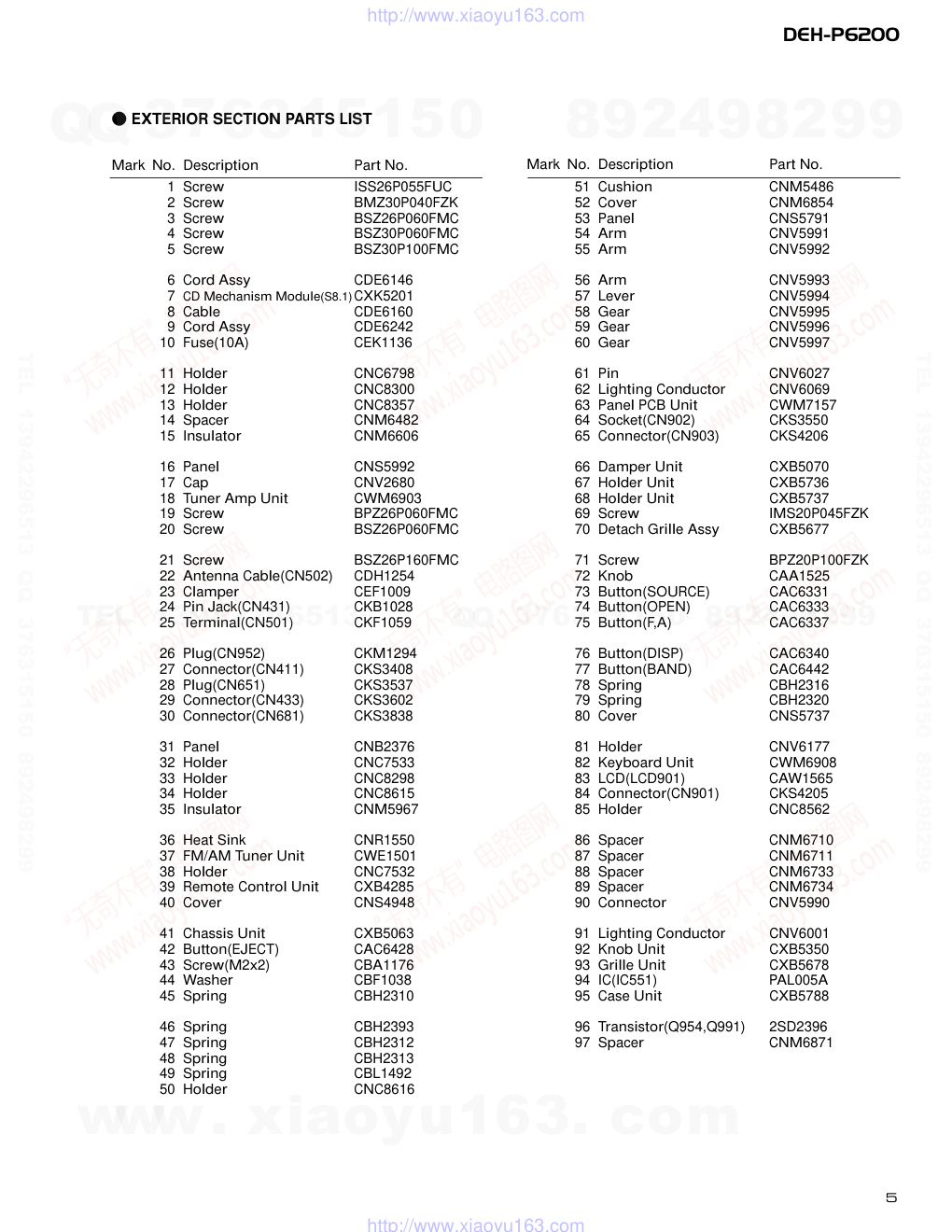
1 Screw
ISS26P055FUC
2 Screw
BMZ30P040FZK
3 Screw
BSZ26P060FMC
4 Screw
BSZ30P060FMC
5 Screw
BSZ30P100FMC
6 Cord Assy
CDE6146
7 CD Mechanism Module(S8.1)CXK5201
8 Cable
CDE6160
9 Cord Assy
CDE6242
10 Fuse(10A)
CEK1136
11 Holder
CNC6798
12 Holder
CNC8300
13 Holder
CNC8357
14 Spacer
CNM6482
15 Insulator
CNM6606
16 Panel
CNS5992
17 Cap
CNV2680
18 Tuner Amp Unit
CWM6903
19 Screw
BPZ26P060FMC
20 Screw
BSZ26P060FMC
21 Screw
BSZ26P160FMC
22 Antenna Cable(CN502)
CDH1254
23 Clamper
CEF1009
24 Pin Jack(CN431)
CKB1028
25 Terminal(CN501)
CKF1059
26 Plug(CN952)
CKM1294
27 Connector(CN411)
CKS3408
28 Plug(CN651)
CKS3537
29 Connector(CN433)
CKS3602
30 Connector(CN681)
CKS3838
31 Panel
CNB2376
32 Holder
CNC7533
33 Holder
CNC8298
34 Holder
CNC8615
35 Insulator
CNM5967
36 Heat Sink
CNR1550
37 FM/AM Tuner Unit
CWE1501
38 Holder
CNC7532
39 Remote Control Unit
CXB4285
40 Cover
CNS4948
41 Chassis Unit
CXB5063
42 Button(EJECT)
CAC6428
43 Screw(M2x2)
CBA1176
44 Washer
CBF1038
45 Spring
CBH2310
46 Spring
CBH2393
47 Spring
CBH2312
48 Spring
CBH2313
49 Spring
CBL1492
50 Holder
CNC8616
51 Cushion
CNM5486
52 Cover
CNM6854
53 Panel
CNS5791
54 Arm
CNV5991
55 Arm
CNV5992
56 Arm
CNV5993
57 Lever
CNV5994
58 Gear
CNV5995
59 Gear
CNV5996
60 Gear
CNV5997
61 Pin
CNV6027
62 Lighting Conductor
CNV6069
63 Panel PCB Unit
CWM7157
64 Socket(CN902)
CKS3550
65 Connector(CN903)
CKS4206
66 Damper Unit
CXB5070
67 Holder Unit
CXB5736
68 Holder Unit
CXB5737
69 Screw
IMS20P045FZK
70 Detach Grille Assy
CXB5677
71 Screw
BPZ20P100FZK
72 Knob
CAA1525
73 Button(SOURCE)
CAC6331
74 Button(OPEN)
CAC6333
75 Button(F,A)
CAC6337
76 Button(DISP)
CAC6340
77 Button(BAND)
CAC6442
78 Spring
CBH2316
79 Spring
CBH2320
80 Cover
CNS5737
81 Holder
CNV6177
82 Keyboard Unit
CWM6908
83 LCD(LCD901)
CAW1565
84 Connector(CN901)
CKS4205
85 Holder
CNC8562
86 Spacer
CNM6710
87 Spacer
CNM6711
88 Spacer
CNM6733
89 Spacer
CNM6734
90 Connector
CNV5990
91 Lighting Conductor
CNV6001
92 Knob Unit
CXB5350
93 Grille Unit
CXB5678
94 IC(IC551)
PAL005A
95 Case Unit
CXB5788
96 Transistor(Q954,Q991)
2SD2396
97 Spacer
CNM6871
- EXTERIOR SECTION PARTS LIST
Mark No. Description
Part No.
Mark No. Description
Part No.
5
www. xiaoyu163. com
QQ 376315150
9
9
2
8
9
4
2
9
8
TEL 13942296513
9
9
2
8
9
4
2
9
8
0
5
1
5
1
3
6
7
3
Q
Q
TEL 13942296513 QQ 376315150 892498299
TEL 13942296513 QQ 376315150 892498299
http://www.xiaoyu163.com
6
DEH-P6200
2.3 CD MECHANISM MODULE
www. xiaoyu163. com
QQ 376315150
9
9
2
8
9
4
2
9
8
TEL 13942296513
9
9
2
8
9
4
2
9
8
0
5
1
5
1
3
6
7
3
Q
Q
TEL 13942296513 QQ 376315150 892498299
TEL 13942296513 QQ 376315150 892498299
http://www.xiaoyu163.com
1 Control Unit
CWX2411
2 Connector(CN802)
CKS2192
3 Connector(CN801)
CKS2193
4 Connector(CN701)
CKS2773
5 Connector(CN101)
CKS3486
6 Screw
BMZ20P030FMC
7 Screw
BSZ20P040FMC
8 Screw(M2x3)
CBA1077
9 Screw(M2x5)
EBA1028
10 Screw
CBA1243
11 Screw(M2x4)
CBA1362
12 Washer
CBF1037
13 Washer
CBF1038
14 Washer
CBF1060
15 •••••
16 Spring
CBH2079
17 Spring
CBH2117
18 Spring
CBH2314
19 Spring
CBH2110
20 Spring
CBH2282
21 Spring
CBH2318
22 •••••
23 Spring
CBH2324
24 Spring
CBH2118
25 Spring
CBH2161
26 Spring
CBH2163
27 Spring
CBH2189
28 Spring
CBH2377
29 Spring
CBH2260
30 Spring
CBH2262
31 Bracket
CNC8568
32 Spring
CBL1369
33 Connector
CDE5531
34 Connector
CDE5532
35 Shaft
CLA3304
36 Screw(M2.6x6)
CBA1458
37 Frame
CNC8565
38 Frame
CNC8749
39 Lever
CNC7546
40 Arm
CNC8663
41 Bracket
CNC8567
42 •••••
43 Spacer
CNM3315
44 Sheet
CNM6659
45 •••••
46 •••••
47 Ball
CNR1189
48 Belt
CNT1086
49 Roller
CNV4509
50 Arm
CNV6037
51 Arm
CNV5247
52 Arm
CNV5248
53 Arm
CNV5249
54 Guide
CNV5254
55 Guide
CNV5255
56 Gear
CNV5257
57 Gear
CNV5256
58 Guide
CNV6272
59 Damper
CNV6010
60 Arm
CNV6096
61 Arm
CNV6031
62 Arm
CNV6211
63 Guide
CNV6012
64 Guide
CNV5510
65 •••••
66 Guide
CNV5751
67 Clamper
CNV6013
68 Gear
CNV5813
69 Motor Unit(M1)
CXB2190
70 Screw Unit
CXB5892
71 Chassis Unit
CXB4797
72 Gear Unit
CXB4728
73 Arm Unit
CXB5753
74 Motor Unit(M2)
CXB2195
75 Lever Unit
CXB4730
76 Arm Unit
CXB4731
77 Motor Unit(M3)
CXB2562
78 Arm Unit
CXB4732
79 Bracket Unit
CXB4795
80 Screw
JFZ20P025FMC
81 Screw
JGZ17P025FZK
82 Washer
YE20FUC
83 Pickup Unit(Service)(P8)
CXX1285
84 Screw
IMS26P030FMC
*
85 PCB
CNX2982
86 Photo-transistor(Q1, 2)
CPT230SX-TU
87 Damper
CNV6011
88 Rack
CNV6014
89 Spring
CBH2315
7
DEH-P6200
Mark No. Description
Part No.
Mark No. Description
Part No.
- CD MECHANISM MODULE SECTION PARTS LIST
www. xiaoyu163. com
QQ 376315150
9
9
2
8
9
4
2
9
8
TEL 13942296513
9
9
2
8
9
4
2
9
8
0
5
1
5
1
3
6
7
3
Q
Q
TEL 13942296513 QQ 376315150 892498299
TEL 13942296513 QQ 376315150 892498299
http://www.xiaoyu163.com
8
DEH-P6200
1
2
3
4
1
2
3
4
D
C
B
A
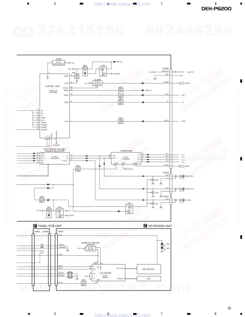
3. BLOCK DIAGRAM AND SCHEMATIC DIAGRAM
3.1 BLOCK DIAGRAM
Q411
R881,882,C881
Q412
IC 411
CA0008AM
IP-BUS DRIVER
28
MUTE
X1
X2
B.U
IL+B
EJECT
CSENS
SW5V
DPDT
KYDT
ROT1(H)
ROT0(L)
BL+B
CDLOAD
clamp
PEE
54
61
100
CDEJET
55
CONT
59
EJTSNS
78
DSCSNS
79
CD5VON
58
VDCONT
56
LCDPW
23
eject
75
DPDT
96
KEYDT
95
KEYIN1
42
KEYIN2
43
1
20
SYSTEM -COM
IC 601(2/2)
PE5106B
M
M
M
35
22
38
42
46
39
CN502
44
63
69
70
54
65
71
46
24
+
19
6
25
32
DI/DO
34 33 41 44 11 12
33
45
55 57
61 74
75
4
3
8
CE2
CK
CE1
SDBW
SL
FMSD
NL1
5
6
CF202
AM 2ND IF 450kHz
T51
Q51
CF51
CF52 CF53
FM MPX
22 10
14
7
12 15 16 8 13
3
2
VDD
B U
VDD
VCC
VCC
VDD
AM RF
AM RF AGC
Q201
Q3
ANT
FM FRONT END
FM/AM 1ST IF 10.7MHz
Q204
1
27
28
2
8
21
6
5
11
22
23
7
24
2
5
4
2
1
3
4
3
FO +
TO +
FO +
TO +
16
23
X201
S801
HOME
S802
CLAMP
CLAMP
CDLOAD
CDEJET
CONT
EJTSNS
CDCSNS
CD5VON
VD
VD
V+5
VD
ED/TD/SD/MD
97
14
5
4
3
98
21
LD
PSW
L +
L —
PD
FDP
TDP
SOP
F
MUTE
R
SOM
COP
COM
LOP
LOM
20
10
11
6
LOUT
24
39
17
12
11
14
13
10
9
21
D802
DISC SENSE
SELECT
SENSE
LOADING
MOTOR
CARRIAGE
MOTOR
SPINDLE
MOTOR
D801
28 DSCSNS
CD5VON
1
CDLOAD
LD +
MD
MD
LD
2
1
ANT1 TV
ANT2 TV
RF TV
HOLOGRAM
UNIT
FOCUS ACT
TRACKING ACT
MIXER,IF AMP DET
IC 1
PML002A
IC 3
BR9010FV
IC 501
S-81250SGUP
POWER ON MUTE
EEPROM
IC 601
TA2063F
IC 2 PM4008A
IC 201
UPD63710GC
IC 301
BA5985FM
CD DRIVER
RF-AMP,SERVO,DSP,DAC
LPF
CN701
CN802
CN801
CN101
5V REGULATOR
IC 701
BA05SFP
PICKUP UNIT(SERVICE)(P8)
BUS—
B.U
BUS+
BUS+L
BUS—L
5
8
1
7
11
1
2
8
6
5
TX
RX
IPPW
swvdd
44
csens
ILMPW
B.U
VDD
B.U
2
10
11
12
14
13
4
8
5
FLAP IL—
6
7
CN651
CN681
CN411
Q652
B.U
Q655
Q654
Q653
Q651
Q656
Q992
Q991
A TUNER AMP UNIT
B FM/AM TUNER UNIT
D CONTROL UNIT
E PHOTO UNIT(S8)
BZ601
ALARM
BUZZER
DFS
ALARM
16
TEMP
81
X601
TH601
15
17
4
19
20
14
3
2
18
1
FLPILM
77
www. xiaoyu163. com
QQ 376315150
9
9
2
8
9
4
2
9
8
TEL 13942296513
9
9
2
8
9
4
2
9
8
0
5
1
5
1
3
6
7
3
Q
Q
TEL 13942296513 QQ 376315150 892498299
TEL 13942296513 QQ 376315150 892498299
http://www.xiaoyu163.com
9
DEH-P6200
5
6
7
8
5
6
7
8
REAR RCA
C
11
1
adpw
bsens
asens
VDD
B.U
B.U
B.U
5
6
1
B.U
NL1
7
91
92
93
48
83
22
SD
SL
SDBW
PCE1
tunpck
tunpce@
tunpdo
ASENBO
10
FL
11
RL
9
B.U
SYSPW
IL+B
COMGND
CSENS
SW5V
DPDT
KYDT
KEYIN1
KEYIN2
BL+B
Preout_L
23
10
12
9
11
RL—
21
RL+
3
FL—
5
FL+
FL—
FL+
RL—
RL+
8
B.REM
RLO
FLO
SLO
7
MUTE
5
ILL
6
ACC
4
ALARM
2
GND
1
BACK UP
BACK UP
GND
TELIN
isens
DRELAY
(VDD)
76
38
74
TUN L
40
BUS+L
43
BUS—L
44
CD L
41
DFS
35
10
99
97
32
98
25
86 85 24
72
FLIN
12
RLIN
14
22
4
25
SYSTEM -COM
RESET
ALARM
POWER AMP
IC 601(1/2)
PE5106B
IC 451
PML004AF
IC 631
S-80734ANDYI
IC 851
TPD1018F
IC 551
PAL005A
IC 902
RS-140
reset
VDD
Q601
Q952
Q959
Q953
Q951
Q434
Q431
SYSPW
Q551
Q957
Q954
Q955
D904
D903
Q905
Q958
DALMON
TX
RX
IPPW
DALMON
DALMON
ELECTRONIC VOLUME/
SOURCE SELECTOR
SYS+B
B.REM
STBY
MUTE
REMOTE CONTROL
SENSOR
IC 901
PD6279
LCD DRIVER
KEY MATRIX
LCD
OPT IN
1
11
8
7
9
6
5
3
4
11
2
8
7
5
6
10
11
12
14
13
4
3
4
6
5
7
8
14
10
2
4
SI
SO
X0
X1
dim
KEY DATA
LCD DATA
REMIN
VCC
53
52
57
X901
58
61
48 50
60
CN903
CN901
CN902
S930
KEYBOARD UNIT
F PANEL PCB UNIT
SUB W.
CN433
CN431
ALARM
ACC
RL—
RL+
ILL
MUTE
FL—
FL+
B.REM
Q432
FRONT RCA
Q433
2
1
2
CN952
1
2
5
6
www. xiaoyu163. com
QQ 376315150
9
9
2
8
9
4
2
9
8
TEL 13942296513
9
9
2
8
9
4
2
9
8
0
5
1
5
1
3
6
7
3
Q
Q
TEL 13942296513 QQ 376315150 892498299
TEL 13942296513 QQ 376315150 892498299
http://www.xiaoyu163.com
CN902
IL GND
BL+
IL +B
CSENS
SW5V
uGND
DPDT
KYDT
ROT0(L)
ROT1(H)
NC
NC
CN901
CN903
10
DEH-P6200
1
2
3
4
1
2
3
4
D
C
B
A
3.2 OVERALL CONNECTION DIAGRAM(GUIDE PAGE)
Note: When ordering service parts, be sure to refer to “EXPLODED VIEWS AND PARTS LIST” or “ELECTRICAL PARTS
LIST”.
A-a
A-b
A-a
A-b
A-b
A-a
Large size
SCH diagram
Guide page
Detailed page
A
A-a
A
B
E
D
F
TUNER AMP UNIT
FM/AM TUNER UNIT
CD MECHANISM
MODULE
PANEL PCB UNIT
C
KEYBOARD
UNIT
www. xiaoyu163. com
QQ 376315150
9
9
2
8
9
4
2
9
8
TEL 13942296513
9
9
2
8
9
4
2
9
8
0
5
1
5
1
3
6
7
3
Q
Q
TEL 13942296513 QQ 376315150 892498299
TEL 13942296513 QQ 376315150 892498299
http://www.xiaoyu163.com
S-CD:36.5dBs
CEK1136
11
DEH-P6200
5
6
7
8
5
6
7
8
D
C
B
A
A-b
A
www. xiaoyu163. com
QQ 376315150
9
9
2
8
9
4
2
9
8
TEL 13942296513
9
9
2
8
9
4
2
9
8
0
5
1
5
1
3
6
7
3
Q
Q
TEL 13942296513 QQ 376315150 892498299
TEL 13942296513 QQ 376315150 892498299
http://www.xiaoyu163.com
12
DEH-P6200
1
2
3
4
1
2
3
4
D
C
B
A
A-a
A
B
TUNER AMP UNIT
FM/AM TUNER UNIT
1
2
3
4
5
www. xiaoyu163. com
QQ 376315150
9
9
2
8
9
4
2
9
8
TEL 13942296513
9
9
2
8
9
4
2
9
8
0
5
1
5
1
3
6
7
3
Q
Q
TEL 13942296513 QQ 376315150 892498299
TEL 13942296513 QQ 376315150 892498299
http://www.xiaoyu163.com
13
DEH-P6200
5
6
7
8
5
6
7
8
D
C
B
A
CN902
IL GND
BL+
IL +B
CSENS
SW5V
uGND
DPDT
KYDT
ROT0(L)
ROT1(H)
NC
NC
CN901
CN903
A-a
A-a A-b
E
D
CD MECHANISM
MODULE
PANEL PCB UNIT
F
6
KEYBOARD
UNIT
C
www. xiaoyu163. com
QQ 376315150
9
9
2
8
9
4
2
9
8
TEL 13942296513
9
9
2
8
9
4
2
9
8
0
5
1
5
1
3
6
7
3
Q
Q
TEL 13942296513 QQ 376315150 892498299
TEL 13942296513 QQ 376315150 892498299
http://www.xiaoyu163.com
14
1
2
3
4
1
2
3
4
D
C
B
A
S-CD:36.5dBs
A-a A-b
A-b
DEH-P6200
1
2
3
4
5
www. xiaoyu163. com
QQ 376315150
9
9
2
8
9
4
2
9
8
TEL 13942296513
9
9
2
8
9
4
2
9
8
0
5
1
5
1
3
6
7
3
Q
Q
TEL 13942296513 QQ 376315150 892498299
TEL 13942296513 QQ 376315150 892498299
http://www.xiaoyu163.com
15
DEH-P6200
5
6
7
8
5
6
7
8
D
C
B
A
CEK1136
A-b
A-a A-b
6
www. xiaoyu163. com
QQ 376315150
9
9
2
8
9
4
2
9
8
TEL 13942296513
9
9
2
8
9
4
2
9
8
0
5
1
5
1
3
6
7
3
Q
Q
TEL 13942296513 QQ 376315150 892498299
TEL 13942296513 QQ 376315150 892498299
http://www.xiaoyu163.com
16
DEH-P6200
1
2
3
4
1
2
3
4
D
C
B
A
B
3.3 FM/AM TUNER UNIT
B
A
KV1410(23)
Mark
None
F0
F65
F125
A0
A74
A125
Band
–
FM
FM
FM
AM
AM
AM
Input Level
–
0dBf
65dBf
125dBf
0dBµ
74dBµ
125dBµ
DAN217U
DAN217U
FM/AM TUNER UNIT
www. xiaoyu163. com
QQ 376315150
9
9
2
8
9
4
2
9
8
TEL 13942296513
9
9
2
8
9
4
2
9
8
0
5
1
5
1
3
6
7
3
Q
Q
TEL 13942296513 QQ 376315150 892498299
TEL 13942296513 QQ 376315150 892498299
http://www.xiaoyu163.com
17
DEH-P6200
5
6
7
8
5
6
7
8
D
C
B
A
B
KV1410(23)
www. xiaoyu163. com
QQ 376315150
9
9
2
8
9
4
2
9
8
TEL 13942296513
9
9
2
8
9
4
2
9
8
0
5
1
5
1
3
6
7
3
Q
Q
TEL 13942296513 QQ 376315150 892498299
TEL 13942296513 QQ 376315150 892498299
http://www.xiaoyu163.com
18
DEH-P6200
1
2
3
4
1
2
3
4
D
C
B
A
C
3.4 KEYBOARD UNIT
C KEYBOARD UNIT
www. xiaoyu163. com
QQ 376315150
9
9
2
8
9
4
2
9
8
TEL 13942296513
9
9
2
8
9
4
2
9
8
0
5
1
5
1
3
6
7
3
Q
Q
TEL 13942296513 QQ 376315150 892498299
TEL 13942296513 QQ 376315150 892498299
http://www.xiaoyu163.com
19
DEH-P6200
5
6
7
8
5
6
7
8
D
C
B
A
ROTARY VR
C
F CN903
www. xiaoyu163. com
QQ 376315150
9
9
2
8
9
4
2
9
8
TEL 13942296513
9
9
2
8
9
4
2
9
8
0
5
1
5
1
3
6
7
3
Q
Q
TEL 13942296513 QQ 376315150 892498299
TEL 13942296513 QQ 376315150 892498299
http://www.xiaoyu163.com
DEH-P6200
1
2
3
4
1
2
3
4
D
C
B
A
BA05SFP
(SERVICE)(P8)
PICKUP UNIT
PHOTO UNIT(S8)
CONTROL UNIT
SPINDLE MOTOR
Q2 CPT230SX-TU
Q1 CPT230SX-TU
M3 CXB2562
CARRIAGE MOTOR
M1 CXB2190
M2 CXB2195
LOADING MOTOR
RF-AMP, SE
5V REGULATOR
CD DRIVER
CN101
CN802
CN801
3.5 CD MECHANISM MODULE
E
D
E
D
20
www. xiaoyu163. com
QQ 376315150
9
9
2
8
9
4
2
9
8
TEL 13942296513
9
9
2
8
9
4
2
9
8
0
5
1
5
1
3
6
7
3
Q
Q
TEL 13942296513 QQ 376315150 892498299
TEL 13942296513 QQ 376315150 892498299
http://www.xiaoyu163.com
21
DEH-P6200
5
6
7
8
5
6
7
8
D
C
B
A
MP, SERVO, DSP, DAC, LPF
SWITCHES:
CONTROL UNIT
S801 : HOME SWITCH.....ON-OFF
S802 : CLAMP SWITCH....ON-OFF
The underlined indicates the switch position.
CN701
A CN681
D
www. xiaoyu163. com
QQ 376315150
9
9
2
8
9
4
2
9
8
TEL 13942296513
9
9
2
8
9
4
2
9
8
0
5
1
5
1
3
6
7
3
Q
Q
TEL 13942296513 QQ 376315150 892498299
TEL 13942296513 QQ 376315150 892498299
http://www.xiaoyu163.com
22
DEH-P6200
1 RFI
0.5V/div. 0.5µs/div.
Normal mode: play
1 CH1: RFI
1V/div.
2 CH2: MIRR
5V/div.
Test mode: Tracking open
0.5ms/div.
1 CH1: RFI
1V/div.
2 CH2: MIRR
5V/div.
Normal mode: The defect part
passes 800µm
0.5ms/div.
3 CH1: FD
0.5V/div.
4 CH2: FO+
2V/div.
Test mode: No disc, Focus close
0.2s/div.
3 CH1: FD
0.5V/div.
5 CH2: FOK
2V/div.
Normal mode: Focus close
0.2s/div.
6 CH1: FE
0.5V/div.
7 CH2: XSI
2V/div.
Normal mode: Focus close
1ms/div.
REFO →
8 CH1: TE
0.5V/div.
9 CH2: TD
0.5V/div.
Test mode: 32 tracks jump (FWD)
0.5ms/div.
8 CH1: TE
0.5V/div.
9 CH2: TD
0.5V/div.
Test mode: Single jump (FWD)
0.5ms/div.
8 CH1: TE
0.5V/div.
9 CH2: TD
0.5V/div.
Test mode: 100 tracks jump (FWD)
5ms/div.
6 CH1: FE
0.1V/div.
3 CH2: FD
0.2V/div.
Normal mode: Play
20ms/div.
3 CH1: FD
0.5V/div.
0 CH2: MD
1V/div.
Normal mode: Focus close (12cm)
0.5s/div.
3 CH1: FD
0.5V/div.
0 CH2: MD
1V/div.
Normal mode: Focus close (8cm)
0.5s/div.
REFO →
REFO →
REFO →
REFO →
REFO →
REFO →
GND →
REFO →
REFO →
REFO →
REFO →
REFO →
REFO →
REFO →
REFO →
REFO →
REFO →
REFO →
REFO →
- Waveforms
Note:1. The encircled numbers denote measuring pointes in the circuit diagram.
2. Reference voltage
REFO:2.5V
REFO →
REFO →
REFO →
REFO →
www. xiaoyu163. com
QQ 376315150
9
9
2
8
9
4
2
9
8
TEL 13942296513
9
9
2
8
9
4
2
9
8
0
5
1
5
1
3
6
7
3
Q
Q
TEL 13942296513 QQ 376315150 892498299
TEL 13942296513 QQ 376315150 892498299
http://www.xiaoyu163.com
23
DEH-P6200
8 CH1: TE
0.2V/div.
9 CH2: TD
0.2V/div.
Normal mode: play
8 CH1: TE
0.5V/div.
! CH2: SD
0.5V/div.
TEST mode: 100 Tracks jump(FWD)
5ms/div.
0 MD
0.5V/div.
0.1s/div.
Normal mode: Play (12cm)
0 MD
1V/div.
10ms/div.
Normal mode:
Long Search (12cm)
@ EFM
1V/div.
5µs/div.
Normal mode: play
8 CH1: TE
1V/div.
# CH2: TEC
1V/div.
Test mode: Focus close
Tracking open
2ms/div.
8 CH1: TE
0.5V/div.
6 CH2: FE
0.5V/div.
Normal mode: AGC after focus close
0.2s/div.
$ PLCK
2V/div.
0.5µs/div.
Normal mode: play
20ms/div.
% SCKO
2V/div.
1µs/div.
Normal mode: play
^ Dout
2V/div.
10µs/div.
Normal mode: play
& LRCK
2V/div.
20µs/div.
Normal mode: play
* VD
5V/div.
50ms/div.
Normal mode: No disc
GND →
REFO →
REFO →
GND →
REFO →
REFO →
REFO →
REFO →
REFO →
REFO →
REFO →
REFO →
REFO →
GND →
REFO →
GND →
REFO →
GND →
REFO →
GND →
REFO →
www. xiaoyu163. com
QQ 376315150
9
9
2
8
9
4
2
9
8
TEL 13942296513
9
9
2
8
9
4
2
9
8
0
5
1
5
1
3
6
7
3
Q
Q
TEL 13942296513 QQ 376315150 892498299
TEL 13942296513 QQ 376315150 892498299
http://www.xiaoyu163.com
24
DEH-P6200
( CH1: R OUT
1V/div.
) CH2: L OUT
1V/div.
Normal mode: Play (1kHz 0dB)
6 CH1: FE
0.2V/div.
3 CH2: FD
0.5V/div.
Normal mode: During AGC
1ms/div.
8 CH1: TE
0.2V/div.
9 CH2: TD
0.5V/div.
Normal mode: During AGC
1 CH1: RFI
1V/div.
⁄ CH2: HOLD
5V/div.
Normal mode: The defect part passes
800µm(B.D)
0.2ms/div.
1ms/div.
0.5ms/div.
3 CH1: FD
0.5V/div.
⁄ CH2: HOLD
5V/div.
Normal mode: The defect part passes
800µm(B.D)
0.5ms/div.
9 CH1: TD
0.1V/div.
⁄ CH2: HOLD
5V/div.
Normal mode: The defect part passes
800µm(B.D)
0.5ms/div.
REFO →
REFO →
REFO →
REFO →
REFO →
REFO →
REFO →
REFO →
REFO →
REFO →
REFO →
REFO →
www. xiaoyu163. com
QQ 376315150
9
9
2
8
9
4
2
9
8
TEL 13942296513
9
9
2
8
9
4
2
9
8
0
5
1
5
1
3
6
7
3
Q
Q
TEL 13942296513 QQ 376315150 892498299
TEL 13942296513 QQ 376315150 892498299
http://www.xiaoyu163.com
25
DEH-P6200
1
2
3
4
1
2
3
4
D
C
B
A
ILGND
IL+B
NC
BL+B
FLAP IL+
FLAP IL-
CSENS
EJECT
uGND
SW5V
DPDT
KYDT
ROT0(L)
ROT1(H)
IL GND
BL+
IL +B
CSENS
SW5V
uGND
DPDT
KYDT
ROT0(L)
ROT1(H)
NC
NC
EJECT
F
3.6 PANEL PCB UNIT
F
PANEL PCB UNIT
A CN651
C CN901
www. xiaoyu163. com
QQ 376315150
9
9
2
8
9
4
2
9
8
TEL 13942296513
9
9
2
8
9
4
2
9
8
0
5
1
5
1
3
6
7
3
Q
Q
TEL 13942296513 QQ 376315150 892498299
TEL 13942296513 QQ 376315150 892498299
http://www.xiaoyu163.com
26
DEH-P6200
1
2
3
4
1
2
3
4
D
C
B
A
4. PCB CONNECTION DIAGRAM
4.1 TUNER AMP UNIT
NOTE FOR PCB DIAGRAMS
1. The parts mounted on this PCB
include all necessary parts for
several destination.
For further information for
respective destinations, be sure
to check with the schematic dia-
gram.
2. Viewpoint of PCB diagrams
A
A
Capacitor
Connector
P.C.Board
Chip Part
SIDE A
SIDE B
TUNER AMP UNIT
CORD ASSY
CN701
D
www. xiaoyu163. com
QQ 376315150
9
9
2
8
9
4
2
9
8
TEL 13942296513
9
9
2
8
9
4
2
9
8
0
5
1
5
1
3
6
7
3
Q
Q
TEL 13942296513 QQ 376315150 892498299
TEL 13942296513 QQ 376315150 892498299
http://www.xiaoyu163.com
27
DEH-P6200
5
6
7
8
5
6
7
8
D
C
B
A
A
SIDE A
B
F CN902
CORD ASSY
www. xiaoyu163. com
QQ 376315150
9
9
2
8
9
4
2
9
8
TEL 13942296513
9
9
2
8
9
4
2
9
8
0
5
1
5
1
3
6
7
3
Q
Q
TEL 13942296513 QQ 376315150 892498299
TEL 13942296513 QQ 376315150 892498299
http://www.xiaoyu163.com
28
DEH-P6200
1
2
3
4
1
2
3
4
D
C
B
A
A
A
TUNER AMP UNIT
www. xiaoyu163. com
QQ 376315150
9
9
2
8
9
4
2
9
8
TEL 13942296513
9
9
2
8
9
4
2
9
8
0
5
1
5
1
3
6
7
3
Q
Q
TEL 13942296513 QQ 376315150 892498299
TEL 13942296513 QQ 376315150 892498299
http://www.xiaoyu163.com
29
DEH-P6200
5
6
7
8
5
6
7
8
D
C
B
A
A
SIDE B
www. xiaoyu163. com
QQ 376315150
9
9
2
8
9
4
2
9
8
TEL 13942296513
9
9
2
8
9
4
2
9
8
0
5
1
5
1
3
6
7
3
Q
Q
TEL 13942296513 QQ 376315150 892498299
TEL 13942296513 QQ 376315150 892498299
http://www.xiaoyu163.com
30
DEH-P6200
1
2
3
4
1
2
3
4
D
C
B
A
4.2 FM/AM TUNER UNIT
B
SIDE A
B
FM/AM TUNER UNIT
A
www. xiaoyu163. com
QQ 376315150
9
9
2
8
9
4
2
9
8
TEL 13942296513
9
9
2
8
9
4
2
9
8
0
5
1
5
1
3
6
7
3
Q
Q
TEL 13942296513 QQ 376315150 892498299
TEL 13942296513 QQ 376315150 892498299
http://www.xiaoyu163.com
31
DEH-P6200
1
2
3
4
1
2
3
4
D
C
B
A
B
SIDE B
B
FM/AM TUNER UNIT
www. xiaoyu163. com
QQ 376315150
9
9
2
8
9
4
2
9
8
TEL 13942296513
9
9
2
8
9
4
2
9
8
0
5
1
5
1
3
6
7
3
Q
Q
TEL 13942296513 QQ 376315150 892498299
TEL 13942296513 QQ 376315150 892498299
http://www.xiaoyu163.com
32
DEH-P6200
1
2
3
4
1
2
3
4
D
C
B
A
4.3 KEYBOARD UNIT
CN903
F
C
C
SIDE A
KEYBOARD UNIT
C
KEYBOARD UNIT
SIDE B
www. xiaoyu163. com
QQ 376315150
9
9
2
8
9
4
2
9
8
TEL 13942296513
9
9
2
8
9
4
2
9
8
0
5
1
5
1
3
6
7
3
Q
Q
TEL 13942296513 QQ 376315150 892498299
TEL 13942296513 QQ 376315150 892498299
http://www.xiaoyu163.com
33
DEH-P6200
1
2
3
4
1
2
3
4
D
C
B
A
F
F
PANEL PCB UNIT
A CN651
SIDE A
SIDE B
F
PANEL PCB UNIT
4.4 PANEL PCB UNIT
C CN901
EJECT
www. xiaoyu163. com
QQ 376315150
9
9
2
8
9
4
2
9
8
TEL 13942296513
9
9
2
8
9
4
2
9
8
0
5
1
5
1
3
6
7
3
Q
Q
TEL 13942296513 QQ 376315150 892498299
TEL 13942296513 QQ 376315150 892498299
http://www.xiaoyu163.com
34
DEH-P6200
1
2
3
4
1
2
3
4
D
C
B
A
4.5 CD MECHANISM MODULE
CONTROL UNIT
HOME
M1 CARRIAGE MOTOR
M2 LOADING MOTOR
M3 SPINDLE MOTOR
PICKUP UNIT(SERVICE)(P8)
CN802
CN681
321
PHOTO UNIT(S8)
SIDE A
A
D
E
D
D E
E
www. xiaoyu163. com
QQ 376315150
9
9
2
8
9
4
2
9
8
TEL 13942296513
9
9
2
8
9
4
2
9
8
0
5
1
5
1
3
6
7
3
Q
Q
TEL 13942296513 QQ 376315150 892498299
TEL 13942296513 QQ 376315150 892498299
http://www.xiaoyu163.com
35
DEH-P6200
D
C
B
A
1
2
3
4
1
2
3
4
CLAMP
SIDE B
CONTROL UNIT
D
D
www. xiaoyu163. com
QQ 376315150
9
9
2
8
9
4
2
9
8
TEL 13942296513
9
9
2
8
9
4
2
9
8
0
5
1
5
1
3
6
7
3
Q
Q
TEL 13942296513 QQ 376315150 892498299
TEL 13942296513 QQ 376315150 892498299
http://www.xiaoyu163.com
36
DEH-P6200
5. ELECTRICAL PARTS LIST
NOTES:
- Parts whose parts numbers are omitted are subject to being not supplied.
- The part numbers shown below indicate chip components.
Chip Resistor
RS1/_S___J,RS1/__S___J
Chip Capacitor (except for CQS.....)
CKS....., CCS....., CSZS.....
=====Circuit Symbol and No.===Part Name
Part No.
---
------
------------------------------------------
-------------------------
Unit Number : CWM6903
Unit Name
: Tuner Amp Unit
MISCELLANEOUS
IC
411
IC
HA12187FP
IC
451
IC
PML004AF
IC
501
IC
S-81250SGUP
IC
551
IC
PAL005A
IC
601
IC
PE5106B
IC
631
IC
S-80734ANDYI
IC
851
IC
TPD1018F
Q
411
Transistor
2SA1586
Q
412
Transistor
DTC124EK
Q
431
Transistor
IMH3A
Q
432
Transistor
IMH3A
Q
433
Transistor
IMH3A
Q
434
Transistor
IMD2A
Q
502
Transistor
2SC2412K
Q
551
Transistor
DTC144EK
Q
601
Transistor
DTA114EK
Q
651
Transistor
2SA933S
Q
652
Transistor
2SB710A
Q
653
Transistor
DTC114EK
Q
654
Transistor
DTC114EU
Q
655
Transistor
2SA1037K
Q
656
Transistor
DTC114EK
Q
851
Transistor
2SA1037K
Q
852
Transistor
DTC124EK
Q
853
Transistor
2SC2412K
Q
951
Transistor
2SA1037K
Q
952
Transistor
2SC3673
Q
953
Transistor
IMX1
Q
954
Transistor
2SD2396
Q
955
Transistor
2SB1238
Q
956
Transistor
DTC114EK
Q
957
Transistor
2SC2412K
Q
958
Transistor
DTC114EK
Q
959
Transistor
IMD2A
Q
991
Transistor
2SD2396
Q
992
Transistor
IMD2A
D
431
Diode
DAN202U
D
432
Diode
1SS133
D
501
Diode
MA3160(LMH)
D
551
Diode
1SR154-400
D
552
Diode
1SR154-400
D
651
Diode
MTZ5R6J(C)
D
652
Diode
DA204K
D
653
Diode
DA204K
D
654
Diode
DA204K
D
655
Diode
DA204K
D
656
Diode
DA204K
D
657
Diode
DA204K
D
658
Diode
DA204K
D
851
LED
BR4361F
D
852
Diode
ERA15-02VH
D
853
Diode
ERA15-02VH
D
951
Diode
ERA15-02VH
D
952
Diode
ERA15-02VH
D
955
Diode
DAN202U
D
956
Diode
HZS6L(B2)
D
957
Diode
HZS7L(C2)
D
958
Diode
HZS6L(C3)
D
959
Diode
HZS9L(A2)
D
960
Diode
HZS9L(B3)
D
961
Diode
ERA15-02VH
D
973
Diode
1SR154-400
D
992
Diode
HZS9L(B1)
L
411
Inductor
LAU3R3J
L
501
Ferri-Inductor
LAU4R7K
L
502
Inductor
CTF1399
L
506
Ferri-Inductor
LAU2R2K
L
601
Inductor
CTF1399
L
603
Ferri-Inductor
LAU2R2K
L
604
Ferri-Inductor
LAU2R2K
L
651
Ferri-Inductor
LAU101K
L
951
Ferri-Inductor
LAU2R2K
TH
601
Thermistor
CCX1037
X
601
Radiator 12.582912MHz
CSS1495
S
651
Switch
CSN1039
BZ
601
Buzzer
CPV1050
AR
501
Arrester
DSP-201M
FM/AM Tuner Unit
CWE1501
RESISTORS
R
411
RS1/10S620J
R
412
RS1/10S101J
R
413
RS1/10S101J
R
414
RS1/10S222J
R
415
RS1/10S332J
R
416
RS1/10S682J
R
417
RS1/10S102J
R
418
RS1/10S102J
R
419
RS1/10S473J
R
420
RS1/10S103J
R
421
RS1/10S473J
R
423
RS1/10S821J
R
424
RS1/10S821J
R
425
RS1/10S223J
R
426
RS1/10S223J
R
427
RS1/10S102J
R
428
RS1/10S102J
R
431
RS1/10S821J
R
432
RS1/10S821J
R
433
RS1/10S821J
R
434
RS1/10S821J
R
435
RS1/10S821J
R
436
RS1/10S821J
R
437
RS1/10S223J
R
438
RS1/10S223J
=====Circuit Symbol and No.===Part Name
Part No.
---
------
------------------------------------------
-------------------------
A
www. xiaoyu163. com
QQ 376315150
9
9
2
8
9
4
2
9
8
TEL 13942296513
9
9
2
8
9
4
2
9
8
0
5
1
5
1
3
6
7
3
Q
Q
TEL 13942296513 QQ 376315150 892498299
TEL 13942296513 QQ 376315150 892498299
http://www.xiaoyu163.com
37
DEH-P6200
R
439
RS1/10S223J
R
440
RS1/10S223J
R
441
RS1/10S223J
R
442
RS1/10S223J
R
443
RS1/10S102J
R
445
RS1/16S0R0J
R
446
RS1/16S0R0J
R
447
RS1/10S0R0J
R
448
RS1/10S0R0J
R
449
RS1/10S0R0J
R
450
RS1/10S0R0J
R
451
RS1/10S0R0J
R
452
RS1/10S0R0J
R
453
RS1/10S0R0J
R
454
RS1/10S0R0J
R
455
RS1/10S0R0J
R
456
RS1/10S0R0J
R
467
RS1/10S0R0J
R
468
RS1/10S0R0J
R
491
RS1/10S102J
R
492
RS1/10S102J
R
501
RS1/10S0R0J
R
502
RS1/10S222J
R
503
RS1/10S222J
R
505
RS1/10S0R0J
R
506
RS1/10S0R0J
R
507
RS1/10S0R0J
R
508
RS1/10S681J
R
511
RS1/10S473J
R
512
RS1/10S681J
R
513
RS1/10S473J
R
514
RS1/10S681J
R
515
RS1/10S473J
R
516
RS1/10S681J
R
517
RS1/10S472J
R
518
RS1/10S103J
R
519
RS1/10S473J
R
520
RS1/10S681J
R
521
RS1/8S151J
R
522
RS1/10S681J
R
523
RS1/10S473J
R
524
RS1/10S0R0J
R
525
RS1/10S0R0J
R
528
RS1/10S0R0J
R
532
RS1/10S681J
R
533
RS1/10S473J
R
541
RS1/10S272J
R
542
RS1/10S272J
R
544
RS1/10S393J
R
545
RS1/10S162J
R
546
RS1/10S162J
R
547
RS1/10S0R0J
R
550
RS1/10S473J
R
551
RS1/10S103J
R
552
RS1/10S103J
R
553
RS1/10S331J
R
603
RS1/10S473J
R
604
RS1/10S102J
R
605
RS1/10S473J
R
606
RS1/10S473J
R
607
RA3C102J
R
610
RS1/10S222J
R
611
RN1/10SE2002D
R
612
RS1/10S473J
R
613
RS1/10S104J
R
614
RS1/10S222J
R
615
RS1/10S222J
R
616
RS1/10S473J
R
617
RS1/10S473J
R
618
RS1/10S473J
R
620
RS1/10S473J
R
621
RS1/10S473J
R
622
RS1/10S102J
R
623
RS1/10S102J
R
625
RS1/10S102J
R
626
RS1/10S822J
R
633
RS1/8S473J
R
634
RS1/10S0R0J
R
637
RS1/16S101J
R
651
RS1/10S222J
R
652
RS1/10S472J
R
653
RS1/10S222J
R
654
RS1/8S472J
R
655
RS1/8S222J
R
656
RS1/8S222J
R
657
RS1/10S473J
R
658
RS1/8S472J
R
659
RS1/8S472J
R
660
RD1/4PU102J
R
661
RS2PMF330J
R
662
RD1/4PU471J
R
663
RS1/10S473J
R
664
RS1/10S473J
R
665
RS1/8S4R7J
R
668
RS1/10S473J
R
669
RS1/8S222J
R
670
RS1/8S472J
R
671
RD1/4PU152J
R
675
RS1/8S222J
R
676
RS1/8S222J
R
677
RS1/10S104J
R
678
RS1/10S473J
R
679
RS1/8S102J
R
680
RS1/8S102J
R
681
RS1/10S681J
R
682
RS1/10S102J
R
683
RS1/10S102J
R
691
RS1/10S473J
R
694
RS1/10S222J
R
851
RS1/10S223J
R
852
RS1/16S223J
R
853
RS1/10S103J
R
854
RS1/10S272J
R
855
RS1/10S223J
R
856
RS1/10S473J
R
857
RS1/16S473J
R
858
RS1/16S473J
R
859
RS1/8S471J
R
867
RS1/16S103J
R
868
RD1/4PU102J
R
870
RS1/10S102J
R
881
RS1/10S103J
R
882
RS1/10S102J
R
951
RD1/4PU102J
R
952
RS1/10S153J
R
953
RS1/16S472J
R
954
RS1/16S472J
R
955
RS1/10S102J
R
956
RD1/4PU102J
R
958
RS1/10S622J
=====Circuit Symbol and No.===Part Name
Part No.
---
------
------------------------------------------
-------------------------
=====Circuit Symbol and No.===Part Name
Part No.
---
------
------------------------------------------
-------------------------
www. xiaoyu163. com
QQ 376315150
9
9
2
8
9
4
2
9
8
TEL 13942296513
9
9
2
8
9
4
2
9
8
0
5
1
5
1
3
6
7
3
Q
Q
TEL 13942296513 QQ 376315150 892498299
TEL 13942296513 QQ 376315150 892498299
http://www.xiaoyu163.com
R
959
RS1/10S473J
R
960
RS1/16S473J
R
961
RS1/10S103J
R
962
RS1/10S473J
R
963
RS1/10S472J
R
964
RS1/10S103J
R
965
RS1/10S473J
R
966
RS1/10S473J
R
967
RS1/8S222J
R
968
RS1/10S102J
R
970
RS1/10S1R0J
R
971
RS1/10S473J
R
972
RS1/10S103J
R
973
RS1/16S473J
R
974
RS1/10S103J
R
975
RS1/16S473J
R
976
RS1/10S152J
R
991
RD1/4PU221J
R
992
RD1/4PU221J
R
993
RS1/10S472J
R
994
RS1/10S222J
CAPACITORS
C
411
CKSQYB104K50
C
412
CKSQYB473K50
C
413
CKSYB105K16
C
414
CKSYB105K16
C
415
CKSYB105K16
C
416
CKSYB105K16
C
431
CEJA100M16
C
432
CEJA100M16
C
433
CEJA100M16
C
434
CEJA100M16
C
435
CEJA100M16
C
436
CEJA100M16
C
443
CEJA220M16
C
451
CKSYB224K25
C
452
CKSYB224K25
C
453
CKSYB474K16
C
454
CKSYB474K16
C
455
CEJANP4R7M16
C
456
CEJANP4R7M16
C
457
CEJANP4R7M16
C
458
CEJANP4R7M16
C
459
CKSQYB473K50
C
460
CKSQYB473K50
C
461
CKSQYB473K50
C
462
CKSQYB473K50
C
463
CEJA470M10
C
464
CKSQYB104K50
C
465
CEJA100M16
C
466
CKSQYB153K50
C
467
CKSQYB473K50
C
468
CKSQYB123K50
C
469
CKSQYB333K50
C
470
CKSQYB153K50
C
491
CKSQYB152K50
C
492
CKSQYB152K50
C
501
CKSQYB103K50
C
502
CKSQYB223K50
C
503
CKSQYB223K50
C
504
CEJA220M16
C
505
CKSQYB102K50
C
506
CEAL101M6R3
C
507
CKSQYB473K50
C
521
CKSRYB102K50
C
522
CEJA101M16
C
523
CEJA101M16
C
533
CKSQYB183K50
C
534
CKSQYB183K50
C
535
CKSQYB472K50
C
536
CCSQCH101J50
C
537
CCSQCH101J50
C
551
CKSYB474K16
C
552
CKSYB474K16
C
553
CKSYB474K16
C
554
CKSYB474K16
C
555
CEJA330M10
C
557
CKSYB225K16
C
558
CEJA100M16
C
559
CKSYB104K50
C
560
3300µF/16V
CCH1330
C
561
CKSQYB473K50
C
563
CKSYB474K16
C
564
CKSYB474K16
C
565
CKSYB474K16
C
566
CKSYB474K16
C
567
CKSYB225K16
C
601
CCSQCH270J50
C
602
CCSQCH270J50
C
603
CKSYB105K16
C
604
CEAL4R7M35
C
607
CCSQCH101J50
C
608
CCSQCH101J50
C
609
CCSQCH101J50
C
610
CCSQCH101J50
C
611
CCSQCH101J50
C
612
CEAL2R2M50
C
651
CCSQCH101J50
C
652
CEAL4R7M35
C
654
CKSYB103K50
C
670
CKSQYB473K50
C
675
CCSQCH101J50
C
710
CKSQYB103K50
C
851
CKSQYB473K50
C
881
CKSQYB473K50
C
951
470µF/16V
CCH1325
C
952
CKSQYB473K50
C
953
CEJA101M10
C
954
CKSQYB473K50
C
955
CEJA101M16
C
956
CKSQYB103K50
C
957
330µF/16V
CCH1326
C
958
CKSQYB102K50
C
959
CKSQYB105K16
C
960
CKSQYB103K50
C
989
470µF/16V
CCH1183
C
991
CKSQYB473K50
C
992
CKSQYB102K50
C
993
CEJA101M10
Unit Number
: CWM6908
Unit Name
: Keyboard Unit
MISCELLANEOUS
IC
901
IC
PD6279A
IC
902
IC
RS-140
Q
906
Transistor
DTC114EU
D
901
Diode
DAN202U
D
902
Diode
DAP202U
D
903
LED
CL170UBX
D
904
LED
CL170UBX
D
908
LED
CL170PGCD
D
909
LED
NSSW440-9159
D
910
LED
NSSW440-9159
38
DEH-P6200
C
=====Circuit Symbol and No.===Part Name
Part No.
---
------
------------------------------------------
-------------------------
=====Circuit Symbol and No.===Part Name
Part No.
---
------
------------------------------------------
-------------------------
www. xiaoyu163. com
QQ 376315150
9
9
2
8
9
4
2
9
8
TEL 13942296513
9
9
2
8
9
4
2
9
8
0
5
1
5
1
3
6
7
3
Q
Q
TEL 13942296513 QQ 376315150 892498299
TEL 13942296513 QQ 376315150 892498299
http://www.xiaoyu163.com
39
DEH-P6200
D
911
LED
NSSW440-9159
D
912
LED
NSSW440-9159
L
901
Inductor
LCTA101J3225
X
901
Radiator 5.00MHz
CSS1423
S
902
Push Switch
CSG1112
S
903
Push Switch
CSG1112
S
904
Spring Switch
CSN1052
S
905
Spring Switch
CSN1051
S
906
Push Switch
CSG1112
S
907
Push Switch
CSG1112
S
908
Push Switch
CSG1112
S
909
Push Switch
CSG1112
S
910
Push Switch
CSG1112
S
911
Push Switch
CSG1112
S
912
Push Switch
CSG1112
S
913
Push Switch
CSG1112
S
914
Push Switch
CSG1112
S
915
Push Switch
CSG1112
S
916
Push Switch
CSG1112
S
917
Push Switch
CSG1112
S
918
Push Switch
CSG1112
S
919
Push Switch
CSG1112
S
920
Push Switch
CSG1112
S
921
Push Switch
CSG1112
S
922
Switch
CSD1040
LCD 901
LCD
CAW1565
RESISTORS
R
901
RS1/10S222J
R
902
RS1/10S222J
R
903
RS1/10S472J
R
904
RS1/10S121J
R
905
RS1/10S2R2J
R
906
RS1/10S470J
R
907
RS1/10S470J
R
909
RS1/8S751J
R
910
RS1/8S751J
R
911
RS1/8S561J
R
912
RS1/8S561J
R
913
RS1/8S561J
R
914
RS1/8S561J
R
915
RS1/8S561J
R
916
RS1/8S561J
R
917
RS1/8S561J
R
918
RS1/8S561J
R
919
RS1/8S561J
R
920
RS1/8S561J
R
921
RS1/8S561J
R
922
RS1/8S561J
R
928
RS1/8S0R0J
R
930
RS1/10S103J
R
931
RS1/8S821J
R
932
RS1/8S821J
R
933
RS1/8S821J
R
934
RS1/8S821J
R
935
RS1/8S152J
R
936
RS1/8S152J
R
937
RS1/8S152J
R
938
RS1/10S431J
R
939
RS1/10S431J
CAPACITORS
C
901
CSZSR100M16
C
902
CKSQYB104K50
C
903
CSZSR100M16
C
904
CKSQYB103K50
C
905
CKSQYB103K50
C
906
CKSQYB103K50
C
907
CKSQYB104K50
C
908
CKSQYB104K50
C
909
CKSQYB104K50
C
910
CKSQYB104K50
C
913
CKSQYB104K50
C
914
CKSQYB104K50
Unit Number
: CWM7157
Unit Name
: PANEL PCB UNIT
MISCELLANEOUS
D
920
LED
CL220PGC
D
921
LED
CL220PGC
S
930
Switch(EJECT)
CSG1112
Unit Number : CWX2411
Unit Name
: Control Unit
MISCELLANEOUS
IC
201
IC
UPD63711GC
IC
301
IC
BA5985FM
IC
701
IC
BA05SFP
Q
101
Transistor
2SB1132
D
801
LED
CL200IRX
D
802
LED
CL200IRX
X
201
Ceramic Oscillator 16.934MHz
CSS1456
S
801
Spring Switch(HOME)
CSN1051
S
802
Spring Switch(CLAMP)
CSN1052
RESISTORS
R
101
RS1/8S120J
R
102
RS1/8S100J
R
103
RS1/16S222J
R
201
RS1/16S104J
R
202
RS1/16S103J
R
203
RS1/16S393J
R
204
RS1/16S103J
R
205
RS1/16S103J
R
206
RS1/16S182J
R
207
RS1/16S123J
R
302
RS1/16S153J
R
303
RS1/16S103J
R
501
RS1/16S102J
R
502
RA4C681J
R
601
RS1/16S102J
R
602
RS1/16S102J
R
605
RS1/16S0R0J
R
606
RS1/16S0R0J
R
801
RS1/8S751J
R
803
RS1/8S751J
R
902
RS1/16S0R0J
R
906
RS1/16S0R0J
CAPACITORS
C
101
CKSRYB102K50
C
102
CKSRYB104K16
C
103
CEV101M6R3
C
104
CEV470M6R3
C
105
CKSQYB334K16
C
106
CKSQYB334K16
C
107
CKSQYB334K16
C
201
CKSRYB104K16
C
202
CKSRYB471K50
C
203
CKSRYB104K16
=====Circuit Symbol and No.===Part Name
Part No.
---
------
------------------------------------------
-------------------------
=====Circuit Symbol and No.===Part Name
Part No.
---
------
------------------------------------------
-------------------------
F
D
www. xiaoyu163. com
QQ 376315150
9
9
2
8
9
4
2
9
8
TEL 13942296513
9
9
2
8
9
4
2
9
8
0
5
1
5
1
3
6
7
3
Q
Q
TEL 13942296513 QQ 376315150 892498299
TEL 13942296513 QQ 376315150 892498299
http://www.xiaoyu163.com
40
DEH-P6200
C
205
CEV101M6R3
C
206
CKSRYB104K16
C
207
CKSRYB104K16
C
208
CKSRYB104K16
C
209
CKSRYB104K16
C
210
CKSRYB332K50
C
211
CKSRYB104K16
C
212
CKSRYB104K16
C
213
CKSRYB392K50
C
214
CKSRYB104K16
C
215
CKSRYB104K16
C
216
CCSRCJ3R0C50
C
217
CCSRCH270J50
C
218
CKSRYB104K16
C
219
CCSRCH181J50
C
220
CCSRCH510J50
C
221
CKSRYB682K25
C
222
CEV220M6R3
C
223
CKSRYB103K25
C
224
CKSRYB224K10
C
301
CEV101M10
C
603
CCSQSL152J50
C
604
CCSQSL152J50
C
702
10µF/10V
CCH1349
C
703
CKSQYB334K16
Unit Number : CWE1501
Unit Name
: FM/AM Tuner Unit
MISCELLANEOUS
IC
1
IC
PML002A
IC
2
IC
PM4008A
IC
3
IC
BR9010FV
Q
1
Transistor
2SC4081
Q
2
Transistor
DTC124EU
Q
3
FET
3SK263
Q
51
Transistor
2SC4081
Q
201
FET
2SK932
Q
202
Transistor
DTC124EU
Q
204
Transistor
2SC4081
D
1
Diode
KV1410(23)
D
2
Diode
1SV248
D
6
Diode
KV1410(23)
D
201
Diode
DAN217U
D
202
Diode
DAN217U
D
903
Diode
KV1410(23)
D
904
Diode
SVC253
L
1
Coil
CTC1155
L
3
Inductor
LCTB1R5K2125
L
4
Coil
CTC1155
L
201
Inductor
LCTB330M1608
L
202
Inductor
CTF1287
L
203
Inductor
LCTA121J3225
L
901
Coil
CTC1154
L
902
Inductor
LCTA3R3J3225
L
904
Inductor
LCTBR47M1608
L
905
Inductor
LCTBR47M1608
T
51
Coil
CTE1132
CF
51
Ceramic Filter
CTF1442
CF
52
Ceramic Filter
CTF1442
CF
53
Ceramic Filter
CTF1442
CF
202
Ceramic Filter
CTF1348
X
901
Crystal Resonator 10.250MHz
CSS1432
RESISTORS
R
1
RS1/16S183J
R
2
RS1/16S103J
R
5
RS1/16S0R0J
R
7
RS1/16S273J
R
8
RS1/16S473J
R
9
RS1/16S223J
R
10
RS1/16S473J
R
11
RS1/16S221J
R
12
RS1/16S103J
R
13
RS1/16S104J
R
16
RS1/16S223J
R
17
RS1/16S221J
R
18
RS1/16S221J
R
19
RS1/16S473J
R
20
RS1/16S470J
R
31
RS1/16S0R0J
R
51
RS1/16S470J
R
52
RS1/16S103J
R
53
RS1/16S103J
R
54
RS1/16S331J
R
55
RS1/16S331J
R
56
RS1/16S560J
R
57
RS1/16S560J
R
58
RS1/16S102J
R
59
RS1/16S225J
R
60
RS1/16S133J
R
61
RS1/16S433J
R
101
RS1/16S333J
R
102
RS1/16S103J
R
103
RS1/16S333J
R
104
RS1/16S562J
R
110
RS1/16S154J
R
111
RS1/16S273J
R
113
RS1/16S222J
R
114
RS1/16S333J
R
115
RS1/16S334J
R
116
RS1/16S473J
R
202
RS1/16S472J
R
203
RS1/16S225J
R
204
RS1/16S102J
R
205
RS1/16S220J
R
206
RS1/16S471J
R
208
RS1/16S104J
R
209
RS1/16S104J
R
210
RS1/16S563J
R
213
RS1/16S223J
R
251
RS1/16S225J
R
902
RS1/16S103J
R
904
RS1/16S473J
R
907
RS1/16S103J
R
908
RS1/16S681J
R
909
RS1/16S473J
R
914
RS1/16S562J
CAPACITORS
C
1
CCSQCH4R0C50
C
6
CKSQYB105K10
C
8
CKSRYB222K50
C
10
CCSRCH220J50
C
11
CCSRCH150J50
C
12
CCSRCH8R0D50
C
14
CCSRCJ3R0C50
C
15
CKSRYB103K50
C
16
CKSRYB222K50
C
17
CKSRYB222K50
=====Circuit Symbol and No.===Part Name
Part No.
---
------
------------------------------------------
-------------------------
=====Circuit Symbol and No.===Part Name
Part No.
---
------
------------------------------------------
-------------------------
B
www. xiaoyu163. com
QQ 376315150
9
9
2
8
9
4
2
9
8
TEL 13942296513
9
9
2
8
9
4
2
9
8
0
5
1
5
1
3
6
7
3
Q
Q
TEL 13942296513 QQ 376315150 892498299
TEL 13942296513 QQ 376315150 892498299
http://www.xiaoyu163.com
41
DEH-P6200
C
18
CCSRCJ3R0C50
C
19
CKSRYB103K50
C
20
CKSRYB103K50
C
21
CKSRYB103K50
C
24
CKSQYB334K16
C
26
CKSRYB472K50
C
30
CCSRCH220J50
C
32
CCSRCH470J50
C
35
CKSRYB103K50
C
51
CKSRYB103K50
C
52
CKSRYB473K16
C
53
CCSRCK2R0C50
C
54
CKSRYB103K50
C
55
CKSRYB104K16
C
56
CKSRYB104K16
C
58
CKSQYB224K16
C
101
CEALNP100M10
C
102
CCSRCH151J50
C
103
CKSRYB473K16
C
105
CKSRYB682K25
C
106
CEALR68M50
C
107
CKSRYB103K50
C
108
CKSQYB474K16
C
109
CKSQYB474K16
C
110
CKSRYB104K16
C
111
CKSRYB104K16
C
112
CKSRYB104K16
C
113
CKSRYB123K25
C
114
CEAL220M6R3
C
115
CKSRYB473K16
C
116
CEAL2R2M50
C
117
CKSRYB102K50
C
120
CKSRYB183K25
C
121
CKSRYB332K50
C
122
CKSRYB562K25
C
123
CKSRYB681K50
C
125
CKSRYB103K50
C
126
CKSRYB103K50
C
127
CEAL2R2M50
C
128
CKSRYB103K50
C
201
CCSRCH471J50
C
202
CCSRCH100D50
C
203
CKSRYB104K16
C
204
CKSRYB332K50
C
205
CKSRYB103K50
C
206
CKSRYB104K16
C
207
CKSRYB473K16
C
208
CCSRCH560J50
C
209
CEAL470M6R3
C
210
CKSRYB103K50
C
211
CKSRYB103K50
C
212
CCSRCH101J50
C
215
CKSRYB223K25
C
216
CKSQYB334K16
C
217
CKSRYB103K50
C
219
CKSQYB105K10
C
220
CKSRYB104K16
C
221
CKSRYB473K16
C
222
CKSQYB334K16
C
223
CKSQYB474K16
C
224
CKSRYB104K16
C
225
CKSRYB272K50
C
226
CKSRYB682K25
C
902
CCSRCH270J50
C
904
CKSRYB223K25
C
905
CKSRYB103K50
C
906
CCSRTH100D50
C
907
CCSRTH150J50
C
909
CCSRTH100D50
C
910
CKSRYB332K50
C
912
CKSQYB474K16
C
913
CKSRYB223K25
C
914
CKSRYB682K25
C
915
CKSQYB223K25
C
916
CKSQYB474K16
C
917
CKSYB475K10
C
918
CKSRYB223K25
C
919
CKSQYB225K10
C
920
CCSRCH270J50
C
921
CCSRCH270J50
C
922
CKSYB105K16
C
923
CKSRYB103K50
Unit Number :
Unit Name
: Photo Unit(S8)
Q
1
Photo-transistor
CPT230SX-TU
Q
2
Photo-transistor
CPT230SX-TU
Miscellaneous Parts List
Pickup Unit(Service)(P8)
CXX1285
M
1
Motor Unit(CARRIAGE)
CXB2190
M
2
Motor Unit(LOADING)
CXB2195
M
3
Motor Unit(SPINDLE)
CXB2562
=====Circuit Symbol and No.===Part Name
Part No.
---
------
------------------------------------------
-------------------------
=====Circuit Symbol and No.===Part Name
Part No.
---
------
------------------------------------------
-------------------------
E
www. xiaoyu163. com
QQ 376315150
9
9
2
8
9
4
2
9
8
TEL 13942296513
9
9
2
8
9
4
2
9
8
0
5
1
5
1
3
6
7
3
Q
Q
TEL 13942296513 QQ 376315150 892498299
TEL 13942296513 QQ 376315150 892498299
http://www.xiaoyu163.com
42
DEH-P6200
1) Precautions
• This unit uses a single power supply (+5V) for the reg-
ulator. The signal reference potential, therefore, is
connected to REFO(approx. 2.5V) instead of GND.
If REFO and GND are connected to each other by mis-
take during adjustments, not only will it be impossi-
ble to measure the potential correctly, but the servo
will malfunction and a severe shock will be applied to
the pick-up. To avoid this, take special note of the fol-
lowing.
Do not connect the negative probe of the measuring
equipment to REFO and GND together. It is especially
important not to connect the channel 1 negative
probe of the oscilloscope to REFO with the channel 2
negative probe connected to GND.
Since the frame of the measuring instrument is usual-
ly at the same potential as the negative probe, change
the frame of the measuring instrument to floating sta-
tus.
If by accident REFO comes in contact with GND,
immediately switch the regulator or power OFF.
• Always make sure the regulator is OFF when connect-
ing and disconnecting the various filters and wiring
required for measurements.
• Before proceeding to further adjustments and mea-
surements after switching regulator ON, let the player
run for about one minute to allow the circuits to stabi-
lize.
• Since the protective systems in the unit's software are
rendered inoperative in test mode, be very careful to
avoid mechanical and /or electrical shocks to the sys-
tem when making adjustment.
• Disc detection during loading and eject operations is
performed by means of a photo transistor in this
unit.Consequently, if the inside of the unit is exposed
to a strong light source when the outer casing is
removed for repairs or adjustment, the following mal-
functions may occur.
*During PLAY, even if the eject button is
pressed,the disc will not be ejected and the unit
will remain in the PLAY mode.
*The unit will not load a disc.
When the unit malfunctions this way, either re-posi-
tion the light source, move the unit or cover the photo
transistor.
2) Test Mode
This mode is used for adjusting the CD mechanism
module of the device.
• Test mode starting procedure
Reset while pressing the 4 and 6 keys together.
• Test mode cancellation
Switch ACC, back-up OFF.
• After pressing the EJECT key, do not press any other
key until the disk is completely ejected.
• If the ] or [ key is pressed while focus search is in
progress, immediately turn the power off (otherwise
the actuator may be damaged due to adhesion of the
lenses).
• Jump operation of TRs other than 100TR continues
after releasing the key. CRG move and 100TR jump
operations are brought into the “Tracking close” sta-
tus when the key is released.
• Powering Off/On resets the jump mode to “Single TR
(91)”, the RF AMP gain setting to 0 dB, and the auto-
matic adjustment value to the initial value.
6. ADJUSTMENT
6.1 CD ADJUSTMENT
www. xiaoyu163. com
QQ 376315150
9
9
2
8
9
4
2
9
8
TEL 13942296513
9
9
2
8
9
4
2
9
8
0
5
1
5
1
3
6
7
3
Q
Q
TEL 13942296513 QQ 376315150 892498299
TEL 13942296513 QQ 376315150 892498299
http://www.xiaoyu163.com
DEH-P6200
43
- Flow Chart
Focus Close
*2
S Curve Check
01 01 01
00 00 00
(99 99 99)
Display
TYP
4
3
Reset
SOURCE
New test mode
6
[
BAND
BAND
BAND
BAND
BAND
3
*2
*1
+6dB
+12dB
*4
*5
6
6
6
6
1
2
1
2
]
]
[
06 06 06
12 12 12
Select CD
Single TR
32TRK
92(82)
CRG Move
94(84)
100TRK
93(83)
Focus Mode
Select
Focus Close/
S Curve Check
CRG-
Auto Adjustment
Display Select
版权声明
1. 本站所有素材,仅限学习交流,仅展示部分内容,如需查看完整内容,请下载原文件。
2. 会员在本站下载的所有素材,只拥有使用权,著作权归原作者所有。
3. 所有素材,未经合法授权,请勿用于商业用途,会员不得以任何形式发布、传播、复制、转售该素材,否则一律封号处理。
4. 如果素材损害你的权益请联系客服QQ:77594475 处理。