先锋PIONEER DEH-P4300RBX1N电路图
 "先锋PIONEER DEH-P4300RBX1N电路图-0")
 "先锋PIONEER DEH-P4300RBX1N电路图-1")
 "先锋PIONEER DEH-P4300RBX1N电路图-2")
 "先锋PIONEER DEH-P4300RBX1N电路图-3")
 "先锋PIONEER DEH-P4300RBX1N电路图-4")
 "先锋PIONEER DEH-P4300RBX1N电路图-5")
 "先锋PIONEER DEH-P4300RBX1N电路图-6")
 "先锋PIONEER DEH-P4300RBX1N电路图-7")
 "先锋PIONEER DEH-P4300RBX1N电路图-8")
 "先锋PIONEER DEH-P4300RBX1N电路图-9")
PIONEER CORPORATION
4-1, Meguro 1-Chome, Meguro-ku, Tokyo 153-8654, Japan
PIONEER ELECTRONICS SERVICE INC.
P.O.Box 1760, Long Beach, CA 90801-1760 U.S.A.
PIONEER EUROPE NV
Haven 1087 Keetberglaan 1, 9120 Melsele, Belgium
PIONEER ELECTRONICS ASIACENTRE PTE.LTD.
253 Alexandra Road, #04-01, Singapore 159936
C PIONEER CORPORATION 2000
K-ZZB. DEC. 2000 Printed in Japan
ORDER NO.
CRT2578
MULTI-CD CONTROL HIGH POWER CD PLAYER WITH RDS TUNER
DEH-P4300R
X1N/EW
Service
Manual
DEH-P4300RB
X1N/EW
DEH-P4300R/X1N/EW
- This service manual should be used together with the following manual(s):
Model No.
Order No.
Mech. Module
Remarks
CX-958
CRT2423
S8.1
CD Mech. Module:Circuit Description, Mech. Description, Disassembly
CONTENTS
1. SAFETY INFORMATION ............................................2
2. EXPLODED VIEWS AND PARTS LIST.......................3
3. BLOCK DIAGRAM AND SCHEMATIC DIAGRAM .....8
4. PCB CONNECTION DIAGRAM ................................26
5. ELECTRICAL PARTS LIST ........................................34
6. ADJUSTMENT..........................................................39
7. GENERAL INFORMATION .......................................43
7.1 DIAGNOSIS ........................................................43
7.1.1 TEST MODE..............................................43
7.1.2 DISASSEMBLY .........................................47
7.1.3 CONNECTOR FUNCTION DESCRIPTION ...51
7.2 PARTS .................................................................52
7.2.1 IC................................................................52
7.2.2 DISPLAY....................................................57
7.3 OPERATIONAL FLOW CHART...........................58
8. OPERATIONS AND SPECIFICATIONS.....................59
www. xiaoyu163. com
QQ 376315150
9
9
2
8
9
4
2
9
8
TEL 13942296513
9
9
2
8
9
4
2
9
8
0
5
1
5
1
3
6
7
3
Q
Q
TEL 13942296513 QQ 376315150 892498299
TEL 13942296513 QQ 376315150 892498299
http://www.xiaoyu163.com
2
DEH-P4300R,P4300RB
- CD Player Service Precautions
1. For pickup unit(CXX1285) handling, please refer
to"Disassembly"(see page 47).
During replacement, handling precautions shall be
taken to prevent an electrostatic discharge(protection
by a short pin).
2. During disassembly, be sure to turn the power off
since an internal IC might be destroyed when a con-
nector is plugged or unplugged.
3. Please checking the grating after changing the ser-
vice pickup unit(see page 41).
1. SAFETY INFORMATION
This service manual is intended for qualified service technicians; it is not meant for the casual do-it-yourselfer.
Qualified technicians have the necessary test equipment and tools, and have been trained to properly and safely repair
complex products such as those covered by this manual.
Improperly performed repairs can adversely affect the safety and reliability of the product and may void the warranty.
If you are not qualified to perform the repair of this product properly and safely; you should not risk trying to do so
and refer the repair to a qualified service technician.
1. Safety Precautions for those who Service this Unit.
•
When checking or adjusting the emitting power of the laser diode exercise caution in order to get safe, reliable
results.
Caution:
1. During repair or tests, minimum distance of 13cm from the focus lens must be kept.
2. During repair or tests, do not view laser beam for 10 seconds or longer.
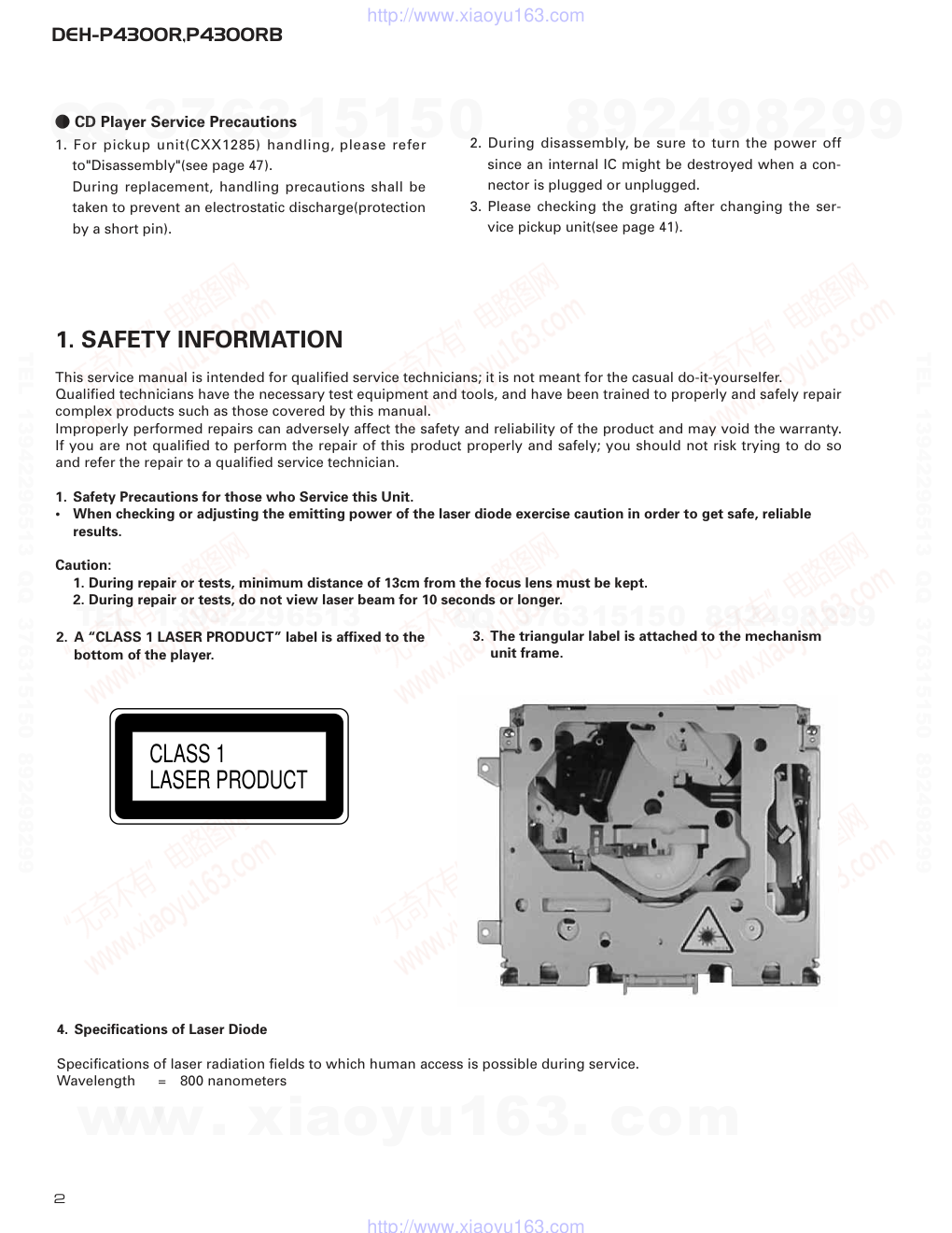
2. A “CLASS 1 LASER PRODUCT” label is affixed to the
bottom of the player.
3. The triangular label is attached to the mechanism
unit frame.
4. Specifications of Laser Diode
Specifications of laser radiation fields to which human access is possible during service.
Wavelength
=
800 nanometers
CLASS 1
LASER PRODUCT
www. xiaoyu163. com
QQ 376315150
9
9
2
8
9
4
2
9
8
TEL 13942296513
9
9
2
8
9
4
2
9
8
0
5
1
5
1
3
6
7
3
Q
Q
TEL 13942296513 QQ 376315150 892498299
TEL 13942296513 QQ 376315150 892498299
http://www.xiaoyu163.com
DEH-P4300R,P4300RB
3
1 Cord Assy
CDE6435
2 Inner Box
CHW1754
*
3 Accessory Assy
CEA2397
4 Screw
CBA1002
5 Handle
CNC5395
6 Bush
CNV3930
*
7 Polyethylene Bag
E36-615
8 Polyethylene Bag
CEG-162
9 Carton(P4300R)
CHG4263
Carton(P4300RB)
CHG4264
10 Contain Box(P4300R)
CHL4263
Contain Box(P4300RB)
CHL4264
11 Protector
CHP2251
12 Protector
CHP2252
13-1 Polyethylene Bag
CEG1116
13-2 Owner's Manual
CRD3297
13-3 Owner's Manual
CRD3298
13-4 Owner's Manual
CRD3299
13-5 Installation Manual
CRD3308
* 13-6 Passport
CRY1013
* 13-7 Warranty Card
CRY1157
* 13-8 Caution Card
CRP1241
14 Case Assy
CXB3520
Mark No. Description
Part No.
Mark No. Description
Part No.
- PACKING SECTION PARTS LIST
NOTE:
- Parts marked by “*” are generally unavailable because they are not in our Master Spare Parts List.
- Screws adjacent to ∇ mark on the product are used for disassembly.
- Owner's Manual, Installation Manual
Model
Part No.
Language
DEH-P4300R/X1N/EW
CRD3297
English, Spanish
DEH-P4300RB/X1N/EW
CRD3298
German, French
CRD3299
Italian, Dutch
CRD3308
English, Spanish, German, French, Italian, Dutch
2. EXPLODED VIEWS AND PARTS LIST
2.1 PACKING
13
14
10
8
12
11
9
1
2
6
5
7
4
3
www. xiaoyu163. com
QQ 376315150
9
9
2
8
9
4
2
9
8
TEL 13942296513
9
9
2
8
9
4
2
9
8
0
5
1
5
1
3
6
7
3
Q
Q
TEL 13942296513 QQ 376315150 892498299
TEL 13942296513 QQ 376315150 892498299
http://www.xiaoyu163.com
4
DEH-P4300R,P4300RB
A
C
B
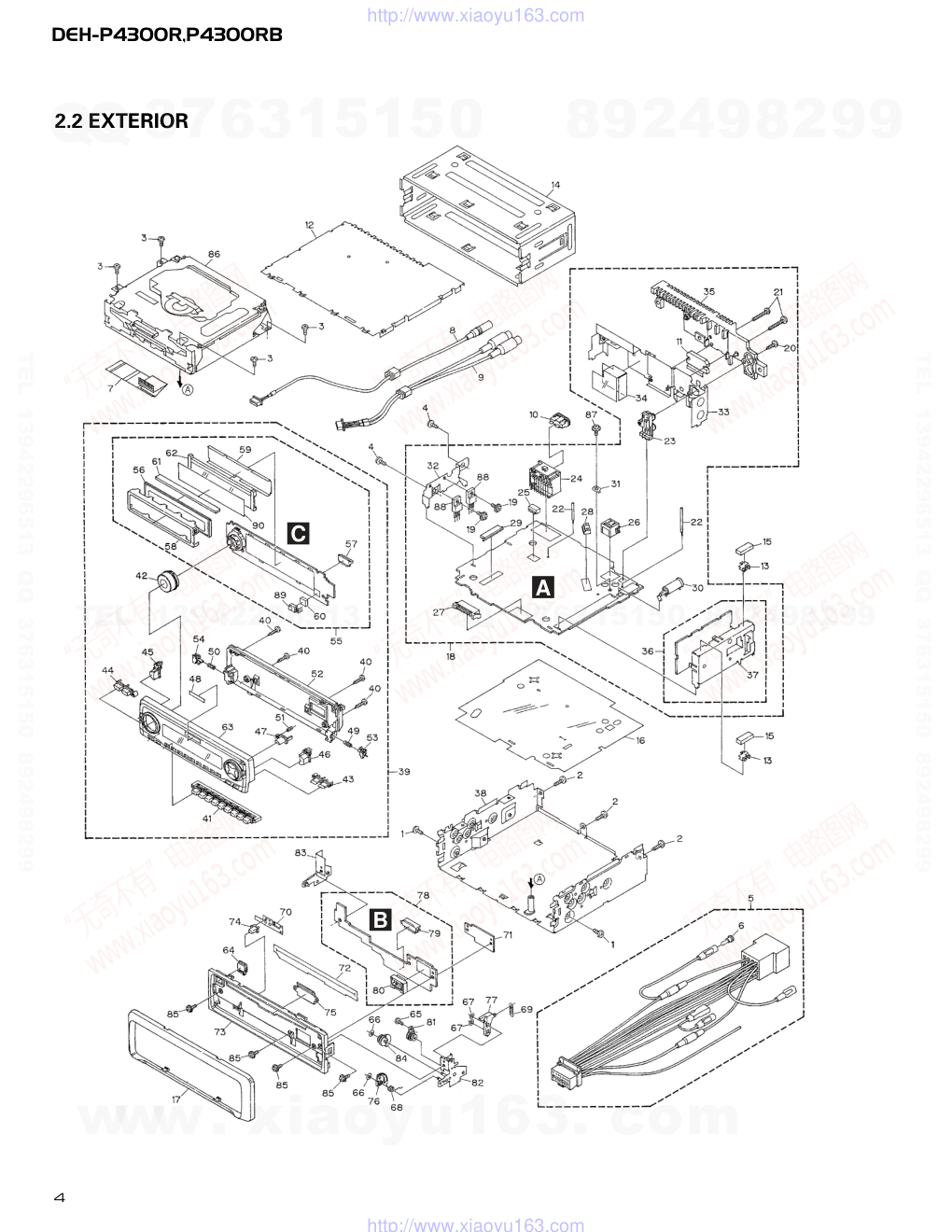
2.2 EXTERIOR
www. xiaoyu163. com
QQ 376315150
9
9
2
8
9
4
2
9
8
TEL 13942296513
9
9
2
8
9
4
2
9
8
0
5
1
5
1
3
6
7
3
Q
Q
TEL 13942296513 QQ 376315150 892498299
TEL 13942296513 QQ 376315150 892498299
http://www.xiaoyu163.com
5
DEH-P4300R,P4300RB
1 Screw
BMZ30P040FZK
2 Screw
BMZ30P100FMC
3 Screw
BSZ26P060FMC
4 Screw
BSZ30P060FMC
5 Cord Assy
CDE6435
6 Cap
CKX-003
7 Cable
CDE6444
8 Cord Assy
CDE6494
9 Cord Assy
CDE6495
10 Fuse(10A)
CEK1136
11 IC(IC361)
PAL006A
12 Case
CNB2686
13 Holder
CNC5704
14 Holder
CNC8659
15 Cushion
CNM4870
16 Insulator
CNM6948
17 Panel
CNS6332
18 Tuner Amp Unit(P4300R) CWM7377
Tuner Amp Unit(P4300RB) CWM7380
19 Screw
ASZ26P060FMC
20 Screw
BPZ26P100FMC
21 Screw
BSZ26P160FMC
22 Clamper
CEF1007
23 Pin Jack(CN351)
CKB1035
24 Plug(CN901)
CKM1330
*
25 Plug(CN201)
CKS1052
26 Connector(CN701)
CKS3408
27 Plug(CN750)
CKS3537
28 Connector(CN331)
CKS3598
29 Connector(CN501)
CKS4398
30 Antenna Jack(CN402)
CKX1056
31 Holder(CN403)
CNC5399
32 Holder
CNC8615
33 Holder
CNC9469
34 Insulator
CNM6949
35 Heat Sink
CNR1583
36 FM/AM Tuner Unit
CWE1562
37 Holder
CNC8815
38 Chassis Unit(P4300R)
CXB6098
Chassis Unit(P4300RB)
CXB6099
39 Detach Grille Assy(P4300R)
CXB6289
Detach Grille Assy(P4300RB) CXB6292
40 Screw
BPZ20P100FZK
41 Button(1-6)
CAC6773
42 Knob(VOLUME)
CAC6775
43 Button(FUNC/AUDIO)
CAC6776
44 Button(SOURCE/DISP)
CAC6777
45 Button(EQ)
CAC6778
46 Button(SFEQ)
CAC6779
47 Button(OPEN)
CAC6780
*
48 Badge
CAH1754
49 Spring
CBH2430
50 Spring
CBH2431
51 Spring
CBH2491
52 Cover
CNS6282
53 Holder
CNV6505
54 Holder
CNV6506
55 Keyboard Unit(P4300R)
CWM7399
Keyboard Unit(P4300RB) CWM7402
56 LCD(P4300R)
CAW1624
LCD(P4300RB)
CAW1625
57 Connector(CN1901)
CKS4205
58 Holder
CNC9053
59 Sheet
CNM6969
60 Cushion
CNM6984
61 Connector
CNV6440
62 Lighting Conductor
CNV6441
63 Sub Grille Assy(P4300R) CXB7150
Sub Grille Assy(P4300RB)CXB7151
64 Button(EJECT)
CAC6839
65 Screw(M2x2)
CBA1176
66 Washer
CBF1038
67 Washer
CBF1039
68 Spring
CBH2428
69 Spring
CBH2429
70 Spring
CBL1512
71 Holder
CNC9096
72 Cover
CNM6854
73 Panel
CNS6278
74 Pin
CNV6486
75 Lighting Conductor
CNV6487
76 Gear
CNV6507
77 Arm
CNV6508
78 Panel Unit
CWM7375
79 Socket(CN1950)
CKS3550
80 Connector(CN1951)
CKS4206
81 Damper Unit
CXB5070
82 Holder Unit
CXB6356
83 Holder Unit
CXB6357
84 Clutch Unit
CXB6358
85 Screw
IMS20P045FZK
86 CD Mechanism Module(S8.1)CXK5201
87 Screw
ISS26P055FUC
88 Transistor(Q510,Q910)
2SD2396
89 IC(IC1902)
SBX8035-H
90 Film(P4300RB)
CNM6983
- EXTERIOR SECTION PARTS LIST
Mark No. Description
Part No.
Mark No. Description
Part No.
www. xiaoyu163. com
QQ 376315150
9
9
2
8
9
4
2
9
8
TEL 13942296513
9
9
2
8
9
4
2
9
8
0
5
1
5
1
3
6
7
3
Q
Q
TEL 13942296513 QQ 376315150 892498299
TEL 13942296513 QQ 376315150 892498299
http://www.xiaoyu163.com
6
DEH-P4300R,P4300RB
D
E
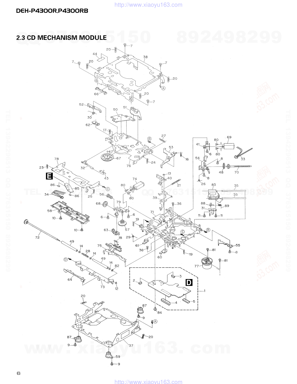
2.3 CD MECHANISM MODULE
www. xiaoyu163. com
QQ 376315150
9
9
2
8
9
4
2
9
8
TEL 13942296513
9
9
2
8
9
4
2
9
8
0
5
1
5
1
3
6
7
3
Q
Q
TEL 13942296513 QQ 376315150 892498299
TEL 13942296513 QQ 376315150 892498299
http://www.xiaoyu163.com
7
DEH-P4300R,P4300RB
1 Control Unit
CWX2411
2 Connector(CN802)
CKS2192
3 Connector(CN801)
CKS2193
4 Connector(CN701)
CKS2773
5 Connector(CN101)
CKS3486
6 Screw
BMZ20P030FMC
7 Screw
BSZ20P040FMC
8 Screw(M2x3)
CBA1077
9 Screw(M2x5)
EBA1028
10 Screw
CBA1243
11 Screw(M2x4)
CBA1362
12 Washer
CBF1037
13 Washer
CBF1038
14 Washer
CBF1060
15 •••••
16 Spring
CBH2079
17 Spring
CBH2117
18 Spring
CBH2314
19 Spring
CBH2110
20 Spring
CBH2282
21 Spring
CBH2318
22 •••••
23 Spring
CBH2324
24 Spring
CBH2118
25 Spring
CBH2161
26 Spring
CBH2163
27 Spring
CBH2189
28 Spring
CBH2377
29 Spring
CBH2260
30 Spring
CBH2262
31 Bracket
CNC8568
32 Spring
CBL1531
33 Connector
CDE5531
34 Connector
CDE5532
35 Shaft
CLA3894
36 Screw(M2.6x6)
CBA1458
37 Frame
CNC8565
38 Frame
CNC8749
39 Lever
CNC9265
40 Arm
CNC8663
41 Bracket
CNC8567
42 •••••
43 Spacer
CNM3315
44 Sheet
CNM6659
45 •••••
46 •••••
47 Ball
CNR1189
48 Belt
CNT1086
49 Roller
CNV4509
50 Arm
CNV6037
51 Arm
CNV5247
52 Arm
CNV5248
53 Arm
CNV5249
54 Guide
CNV5254
55 Guide
CNV5255
56 Gear
CNV5257
57 Gear
CNV5256
58 Guide
CNV6272
59 Damper
CNV6010
60 Arm
CNV6096
61 Arm
CNV6031
62 Arm
CNV6211
63 Guide
CNV6012
64 Guide
CNV5510
65 •••••
66 Guide
CNV5751
67 Clamper
CNV6013
68 Gear
CNV5813
69 Motor Unit(M1)
CXB2190
70 Screw Unit
CXB5892
71 Chassis Unit
CXB4797
72 Gear Unit
CXB4728
73 Arm Unit
CXB5753
74 Motor Unit(M2)
CXB2195
75 Lever Unit
CXB4730
76 Arm Unit
CXB4731
77 Motor Unit(M3)
CXB2562
78 Arm Unit
CXB4732
79 Bracket Unit
CXB4795
80 Screw
JFZ20P025FMC
81 Screw
JGZ17P025FZK
82 Washer
YE20FUC
83 Pickup Unit(Service)(P8)
CXX1285
84 Screw
IMS26P030FMC
*
85 PCB
CNX2982
86 Photo-transistor(Q1, 2)
CPT230SX-TU
87 Damper
CNV6011
88 Rack
CNV6014
89 Spring
CBH2315
Mark No. Description
Part No.
Mark No. Description
Part No.
- CD MECHANISM MODULE SECTION PARTS LIST
www. xiaoyu163. com
QQ 376315150
9
9
2
8
9
4
2
9
8
TEL 13942296513
9
9
2
8
9
4
2
9
8
0
5
1
5
1
3
6
7
3
Q
Q
TEL 13942296513 QQ 376315150 892498299
TEL 13942296513 QQ 376315150 892498299
http://www.xiaoyu163.com
Q420
Q415
Q413
Q416
Q710
Q711
Q411
Q481
IC 481
PM4009A
IC 710
HA12187FP
X481
RDS
DECODER
IP-BUS DRIVER
12
11
20
8
37
MUTE
X1
X2
ILB+
EJECT
CSENS
SW5V
DPDT
KYDT
ROT1
ROT0
BL+B
CDLOAD
clamp
PEE
64
56
100
EJECT
53
CONT
63
EJTSNS
78
DSCSNS
79
CD5VON
55
VDCONT
57
LCDPW
6
EJECTIN
4
DPDT
96
KYDT
95
ROT0
29
ROT1
25
23
20
SYSTEM
CONTROLLER
IC 601(2/2)
PE5202A
CN402
6
21
18
22
19
12 15 16
8
13
3
2
4
ANT
28
27
BUS—
B.U
BUS+
BUS+L
5
8
1
7
1
2
8
6
5
TX
RX
IPPW
SWVDD
77
CSENS
ILMPW
B.U
VDD
B.U
7
10
11
14
12
13
2
8
5
FILM—
6
4
CN750
CN501
CN701
Q751
B.U
Q754
Q755
Q753
Q750
Q752
Q511
Q510
A TUNER AMP UNIT
FM/AM TUNER UNIT
BZ610
ALARM
BUZZER
16
TEMP
81
X610
TH601
15
17
4
19
20
14
3
2
18
1
FLPILM
9
FILM+
5
1
6
72
mute
S750
CN201
5
Q215
Q216
VDD
IC 212
NJM2068MD
2
2
1
IC 3
EEPROM
FM/AM 1ST IF 10.7MHz
T51 Q51 CF51
CF52 CF53
IC1
MIXER, IF AMP, DET.
LDET
COMP
CF202
VCC
DI/DO
CE2
CK
CE1
SDBW
SL
FMSD
NL1
NL2
IC 2 FM MPX
AMANT
FMANT
ATT
ATT
AMRF
FMRF
IMG ADJ
RF ADJ
X901
10.25MHz
ANT ADJ
LOCL
LOCH
AMDET
MPXREF 41kHz
AM 2ND IF
450kHz
CREQ
STIND
L ch
1
14
25
23
Q410
LOCL
VCC
LOCH
VDD
Q414
B.U
5
R ch
7
17
20
24
26
WC
NC
NC
FMLOCL
RFGND
11 DGND
10
VDD
VDD
9
NC
PDIO
CURRQ
mute
Q36
VCC
SYSPW
21
SYSPW
DETACH
SENSE SW
M
M
M
8
21
6
5
11
22
23
7
24
2
1
4
2
1
3
4
3
FO +
TO +
FO +
TO +
16
23
X201
S801
HOME
S802
CLAMP
CLAMP
CDLOAD
CDEJET
CONT
EJTSNS
DSCSNS
CD5VON
VD
VD
V+5
VD
FD/TD/SD/MD
97
14
5
4
3
98
16
LD
LIMIT
L.OUT
PD
FOP
TOP
SOP
F
MUTE
R
SOM
COP
COM
LOP
LOM
6
LOUT
24
39
18
12
11
14
13
10
9
21
D802
DISC SENSE
EJECT
SENSE
LOADING
MOTOR
CARRIAGE
MOTOR
SPINDLE
MOTOR
D801
28 CDEJET
CD5VON
1
CDLOAD
LD +
MD
MD
LD
2
1
HOLOGRAM
UNIT
FOCUS ACT
TRACKING ACT
IC 201
UPD63711GC
IC 301
BA5985FM
CD DRIVER
RF-AMP,SERVO,DSP,DAC,LPF
CN701
CN802
CN801
CN101
5V REGULATOR
IC 701
BA05SFP
PICKUP UNIT(SERVICE)(P8)
D CONTROL UNIT
E PHOTO UNIT (S8)
Q101
8
DEH-P4300R,P4300RB
1
2
3
4
1
2
3
4
D
C
B
A
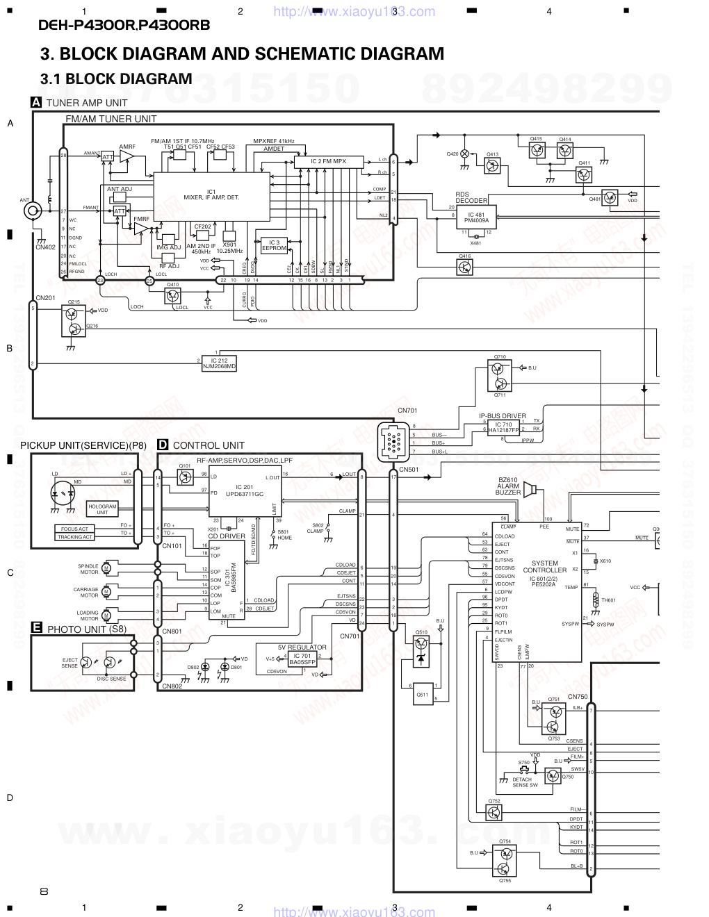
3. BLOCK DIAGRAM AND SCHEMATIC DIAGRAM
3.1 BLOCK DIAGRAM
www. xiaoyu163. com
QQ 376315150
9
9
2
8
9
4
2
9
8
TEL 13942296513
9
9
2
8
9
4
2
9
8
0
5
1
5
1
3
6
7
3
Q
Q
TEL 13942296513 QQ 376315150 892498299
TEL 13942296513 QQ 376315150 892498299
http://www.xiaoyu163.com
C
88
ldet
42
fM/AM
48
11
1
tmute
adpw
bsens
asens
NL2DT
VDD
B.U
B.U
B.U
NL1
7
8
92
93
83
10
22
SD
SL
SDBW
PCE1
PCK
pce@
PDO
ASENBO
10
Fout L
11
Rout L
IL+B
µGND
CSENS
SW5V
DPDT
KYDT
RDT1
RDT0
BL+B
3
7
5
8
6
RL—
5
RL+
23
FL—
21
FL+
RL—
RL+
FL—
FL+
12
B.REM
Lch
TEL
10
ILM
13
ACC
16
GND
15
BACK UP
BACK UP
GND
TELIN
isens
AVREF
DALMON
47
75
38
74
TUN L
41
BUS+L
44
CD L
42
49
99
97
32
98
71
86 85 24
FLIN
14
RLIN
12
22
4
25
SYSTEM
CONTROLLER
RESET
POWER AMP
IC 301
PML008A
IC 603
S-80834ANY
IC 361
PAL006A
IC 1902
SBX8035-H
reset
VDD
Q610
Q913
Q914
Q916
Q359
Q351
SYSPW
Q1901
Q1903
Q1904
Q1902
Q1905
Q917
TX
RX
IPPW
ELECTRONIC VOLUME/
SOURCE SELECTOR
B.REM
STBY
MUTE
REMOTE CONTROL
SENSOR
IC 1903
PD6294A
LCD DRIVER
KEY MATRIX
LCD
OPT IN
1
9
8
7
10
3
5
6
4
11
7
8
4
5
6
10
11
14
12
13
2
4
3
6
5
10
8
7
9
2
3
DPDT
KYDT
X0
X1
DIMMER
KEY DATA
LCD DATA
GRN
REMIN
VDD
9
8
3
X1901
2
7
23
10
11
CN1951
CN1901
CN1950
S1950
KEYBOARD UNIT
B PANEL UNIT
REAR/SW
CN351
ACC
RL—
RL+
ILM
TEL
FL—
FL+
B.REM
RR—
FR—
FL—
RL—
RR+
FR+
FL+
RL+
BACK UP
ILL
GND
B.REM
ACC
2
CN901
12
AMB
S1922
1
CN331
IC 601(1/2)
PE5202A
5
1
Q909
6
Q915
10
20
MUTE
Q341
HFPW
1
40
IN1L
st
39
46
currq
50
51
LOCL
LOCH
VDD
VDD
CELLULAR MUTE
P4300R
7
5
8
6
12
10
13
16
15
10
B.U
SYSPW
Q361
Q910
Q911
mute
Q362
Q912
Q918
VCC
VCC
EJECT
SENSE SW
2
FRONT
9
DEH-P4300R,P4300RB
5
6
7
8
5
6
7
8
D
C
B
A
www. xiaoyu163. com
QQ 376315150
9
9
2
8
9
4
2
9
8
TEL 13942296513
9
9
2
8
9
4
2
9
8
0
5
1
5
1
3
6
7
3
Q
Q
TEL 13942296513 QQ 376315150 892498299
TEL 13942296513 QQ 376315150 892498299
http://www.xiaoyu163.com
CN1901
CN701
200mA
P
DSP-201M
SYSTEM
CL220PGC
R454
0R0
R455
0R0
R784
392 (1/10W)
R789
R788
R787
4
C765
103
C624
223
C634
472
DETACH
IMH3A
EJECT SENSE SW
ANTENNA
C799
473
>
MIC, TEL
For resistors and capacitors in the circuit diagrams, their resistance values or
capacitance values are expressed in codes:
Ex. *Resistors
Code Practical value
123 12k ohms
103 10k ohms
*Capacitors
Code Practical value
103 0.01uF
101/10 100uF/10V
B PANEL UNIT
C KEYBOARD UNIT
D CONTROL UNIT
FM/AM TUNER UNIT
The
the
The
ide
P4300R
P4300RB
FM(100%):-15.5dBs
AM(30%): -26dBs
CD:+4.1dBs
10
DEH-P4300R,P4300RB
1
2
3
4
1
2
3
4
D
C
B
A
3.2 OVERALL CONNECTION DIAGRAM(GUIDE PAGE)
Note: When ordering service parts, be sure to refer to “EXPLODED VIEWS AND PARTS LIST” or “ELECTRICAL PARTS
LIST”.
A-a
A-b
A-a
A-b
A-b
A-a
Large size
SCH diagram
Guide page
Detailed page
A
A-a
B
www. xiaoyu163. com
QQ 376315150
9
9
2
8
9
4
2
9
8
TEL 13942296513
9
9
2
8
9
4
2
9
8
0
5
1
5
1
3
6
7
3
Q
Q
TEL 13942296513 QQ 376315150 892498299
TEL 13942296513 QQ 376315150 892498299
http://www.xiaoyu163.com
11
DEH-P4300R,P4300RB
5
6
7
8
5
6
7
8
D
C
B
A
A-b
A
PE5202A
472/16
600µH
>
CEK1136 10A
FUSE
M CONTROLLER
RR—
FR—
FL—
RL—
RR+
FR+
FL+
RL+
BACK UP
ILL
GND
B.REM
ACC
Q918
2SC2412K
R934
103
R935
223
R936
152 (1/4W)
D926
HZS9L(A2)
D320
DAN202U
IMH3A
IMH3A
DTC124EK
222 (1/10W)
222 (1/10W)
472 (1/10W)
R786
102
H SENSE SW
R781
104
A TUNER AMP UNIT
e > mark found on some component parts indicates
e importance of the safety factor of the part.
erefore, when replacing, be sure to use parts of
entical designation.
FM(100%): +6.6dBs
AM(30%): -3.9dBs
CD:+10.2dBs
IP-BUS:+10.3dBs
FM(100%):+32.6dBs
AM(30%):+23.1dBs
CD:+36.2dBs
IP-BUS:+36.3dBs
CD:+9.4dBs
FM(100%):-15.5dBs
AM(30%): -26dBs
CD: +4.1dBs
IP-BUS: +2.2dBs
IP-BUS:+2.2dBs
www. xiaoyu163. com
QQ 376315150
9
9
2
8
9
4
2
9
8
TEL 13942296513
9
9
2
8
9
4
2
9
8
0
5
1
5
1
3
6
7
3
Q
Q
TEL 13942296513 QQ 376315150 892498299
TEL 13942296513 QQ 376315150 892498299
http://www.xiaoyu163.com
200mA
PE5202A
DSP-201M
SYSTEM CONTROLLER
R454
0R0
R455
0R0
C624
223
C634
472
ANTENNA
>
MIC, TEL
FM/AM TUNER UNIT
P4300R
P4300RB
FM(100%):-15.5dBs
AM(30%): -26dBs
12
DEH-P4300R,P4300RB
1
2
3
4
1
2
3
4
D
C
B
A
A-a
A-a A-b
1
www. xiaoyu163. com
QQ 376315150
9
9
2
8
9
4
2
9
8
TEL 13942296513
9
9
2
8
9
4
2
9
8
0
5
1
5
1
3
6
7
3
Q
Q
TEL 13942296513 QQ 376315150 892498299
TEL 13942296513 QQ 376315150 892498299
http://www.xiaoyu163.com
13
DEH-P4300R,P4300RB
5
6
7
8
5
6
7
8
D
C
B
A
A-a
A-a A-b
B
2
3
4
CN1901
CN701
CL220PGC
R784
392 (1/10W)
R789
222 (1/10W)
R788
222 (1/10W)
R787
472 (1/10W)
C765
103
DETACH SENSE SW
IMH3A
EJECT SENSE SW
C799
473
For resistors and capacitors in the circuit diagrams, their resistance values or
capacitance values are expressed in codes:
Ex. *Resistors
Code Practical value
123 12k ohms
103 10k ohms
*Capacitors
Code Practical value
103 0.01uF
101/10 100uF/10V
B PANEL UNIT
C KEYBOARD UNIT
D CONTROL UNIT
The > mark found
the importance of t
Therefore, when re
identical designatio
CD:+4.1dBs
www. xiaoyu163. com
QQ 376315150
9
9
2
8
9
4
2
9
8
TEL 13942296513
9
9
2
8
9
4
2
9
8
0
5
1
5
1
3
6
7
3
Q
Q
TEL 13942296513 QQ 376315150 892498299
TEL 13942296513 QQ 376315150 892498299
http://www.xiaoyu163.com
14
1
2
3
4
1
2
3
4
D
C
B
A
A-a A-b
A-b
DEH-P4300R,P4300RB
472/16
600µH
ROLLER
IMH3A
IMH3A
A TUNER AMP UNIT
FM(100%): +6.6dBs
AM(30%): -3.9dBs
CD:+10.2dBs
IP-BUS:+10.3dBs
FM(100%):+32.6dBs
AM(30%):+23.1dBs
CD:+36.2dBs
IP-BUS:+36.3dBs
CD:+9.4dBs
FM(100%):-15.5dBs
AM(30%): -26dBs
CD: +4.1dBs
IP-BUS: +2.2dBs
IP-BUS:+2.2dBs
1
www. xiaoyu163. com
QQ 376315150
9
9
2
8
9
4
2
9
8
TEL 13942296513
9
9
2
8
9
4
2
9
8
0
5
1
5
1
3
6
7
3
Q
Q
TEL 13942296513 QQ 376315150 892498299
TEL 13942296513 QQ 376315150 892498299
http://www.xiaoyu163.com
15
DEH-P4300R,P4300RB
5
6
7
8
5
6
7
8
D
C
B
A
A-b
A-a A-b
2
3
4
>
CEK1136 10A
FUSE
RR—
FR—
FL—
RL—
RR+
FR+
FL+
RL+
BACK UP
ILL
GND
B.REM
ACC
Q918
2SC2412K
R934
103
R935
223
R936
152 (1/4W)
D926
HZS9L(A2)
D320
DAN202U
DTC124EK
)
)
R786
102
W
R781
104
rk found on some component parts indicates
ance of the safety factor of the part.
when replacing, be sure to use parts of
esignation.
FM(100%):+32.6dBs
AM(30%):+23.1dBs
CD:+36.2dBs
IP-BUS:+36.3dBs
www. xiaoyu163. com
QQ 376315150
9
9
2
8
9
4
2
9
8
TEL 13942296513
9
9
2
8
9
4
2
9
8
0
5
1
5
1
3
6
7
3
Q
Q
TEL 13942296513 QQ 376315150 892498299
TEL 13942296513 QQ 376315150 892498299
http://www.xiaoyu163.com
REMOTE CON
SENSOR
TA
BAND
DOWN
CAW1624
16
DEH-P4300R,P4300RB
1
2
3
4
1
2
3
4
D
C
B
A
C
3.3 KEYBOARD UNIT(DEH-P4300R/X1N/EW)
www. xiaoyu163. com
QQ 376315150
9
9
2
8
9
4
2
9
8
TEL 13942296513
9
9
2
8
9
4
2
9
8
0
5
1
5
1
3
6
7
3
Q
Q
TEL 13942296513 QQ 376315150 892498299
TEL 13942296513 QQ 376315150 892498299
http://www.xiaoyu163.com
17
DEH-P4300R,P4300RB
5
6
7
8
5
6
7
8
D
C
B
A
C
OTE CONTROL
SENSOR
CL170UBX
C KEYBOARD UNIT
B
CN1951
PANEL UNIT
AUDIO
SFEQ
DISP
FUNC
EQ
SOURCE
PTY
TA
CH3
CH2
CH1
CH4
CH5
CH6
BAND
DOWN
UP
RIGHT
LEFT
R1927
472
www. xiaoyu163. com
QQ 376315150
9
9
2
8
9
4
2
9
8
TEL 13942296513
9
9
2
8
9
4
2
9
8
0
5
1
5
1
3
6
7
3
Q
Q
TEL 13942296513 QQ 376315150 892498299
TEL 13942296513 QQ 376315150 892498299
http://www.xiaoyu163.com
18
DEH-P4300R,P4300RB
1
2
3
4
1
2
3
4
D
C
B
A
REMOTE CONTROL
SENSOR
SUPER RED
SUPER RED
TA
BAND
DOWN
CAW1625
C
3.4 KEYBOARD UNIT(DEH-P4300RB/X1N/EW)
www. xiaoyu163. com
QQ 376315150
9
9
2
8
9
4
2
9
8
TEL 13942296513
9
9
2
8
9
4
2
9
8
0
5
1
5
1
3
6
7
3
Q
Q
TEL 13942296513 QQ 376315150 892498299
TEL 13942296513 QQ 376315150 892498299
http://www.xiaoyu163.com
CONTROL
SOR
CL170UBX
151
151
C KEYBOARD UNIT
B
CN1951
PANEL UNIT
AUDIO
SFEQ
DISP
FUNC
EQ
SOURCE
PTY
A
CH3
CH2
CH1
CH4
CH5
CH6
ND
WN
UP
RIGHT
LEFT
R1927
472
19
DEH-P4300R,P4300RB
5
6
7
8
5
6
7
8
D
C
B
A
C
www. xiaoyu163. com
QQ 376315150
9
9
2
8
9
4
2
9
8
TEL 13942296513
9
9
2
8
9
4
2
9
8
0
5
1
5
1
3
6
7
3
Q
Q
TEL 13942296513 QQ 376315150 892498299
TEL 13942296513 QQ 376315150 892498299
http://www.xiaoyu163.com
BA05SFP
(SERVICE)(P8)
PICKUP UNIT
PHOTO UNIT(S8)
CL203IRXTU
CL203IRXTU
CONTROL UNIT
SPINDLE MOTOR
Q2 CPT230SX-TU
Q1 CPT230SX-TU
M3 CXB2562
CARRIAGE MOTOR
M1 CXB2190
M2 CXB2195
LOADING MOTOR
RF-AMP, SE
5V REGULATOR
CD DRIVER
CN101
CN802
CN801
20
DEH-P4300R,P4300RB
1
2
3
4
1
2
3
4
D
C
B
A
3.5 CD MECHANISM MODULE
E
D
D
E
www. xiaoyu163. com
QQ 376315150
9
9
2
8
9
4
2
9
8
TEL 13942296513
9
9
2
8
9
4
2
9
8
0
5
1
5
1
3
6
7
3
Q
Q
TEL 13942296513 QQ 376315150 892498299
TEL 13942296513 QQ 376315150 892498299
http://www.xiaoyu163.com
MP, SERVO, DSP, DAC, LPF
SWITCHES:
CONTROL UNIT
S801 : HOME SWITCH.....ON-OFF
S802 : CLAMP SWITCH....ON-OFF
The underlined indicates the switch position.
CN701
16.934MHz
Decimal points for resistor
and capacitor fixed values
are expressed as :
2.2 2R2
0.022 R022
←
←
Symbol indicates a resistor.
No differentiation is made between chip resistors and
discrete resistors.
NOTE :
Symbol indicates a capacitor.
No differentiation is made between chip capacitors and
discrete capacitors.
21
DEH-P4300R,P4300RB
5
6
7
8
5
6
7
8
D
C
B
A
CN501
D
A
www. xiaoyu163. com
QQ 376315150
9
9
2
8
9
4
2
9
8
TEL 13942296513
9
9
2
8
9
4
2
9
8
0
5
1
5
1
3
6
7
3
Q
Q
TEL 13942296513 QQ 376315150 892498299
TEL 13942296513 QQ 376315150 892498299
http://www.xiaoyu163.com
22
DEH-P4300R,P4300RB
1 RFI
0.5V/div. 0.5µs/div.
Normal mode: play
1 CH1: RFI
1V/div.
2 CH2: MIRR
5V/div.
Test mode: Tracking open
0.5ms/div.
1 CH1: RFI
1V/div.
2 CH2: MIRR
5V/div.
Normal mode: The defect part
passes 800µm
0.5ms/div.
3 CH1: FD
0.5V/div.
4 CH2: FO+
2V/div.
Test mode: No disc, Focus close
0.2s/div.
3 CH1: FD
0.5V/div.
5 CH2: FOK
2V/div.
Normal mode: Focus close
0.2s/div.
6 CH1: FE
0.5V/div.
7 CH2: XSI
2V/div.
Normal mode: Focus close
1ms/div.
REFO →
8 CH1: TE
0.5V/div.
9 CH2: TD
0.5V/div.
Test mode: 32 tracks jump (FWD)
0.5ms/div.
8 CH1: TE
0.5V/div.
9 CH2: TD
0.5V/div.
Test mode: Single jump (FWD)
0.5ms/div.
8 CH1: TE
0.5V/div.
9 CH2: TD
0.5V/div.
Test mode: 100 tracks jump (FWD)
5ms/div.
6 CH1: FE
0.1V/div.
3 CH2: FD
0.2V/div.
Normal mode: Play
20ms/div.
3 CH1: FD
0.5V/div.
0 CH2: MD
1V/div.
Normal mode: Focus close (12cm)
0.5s/div.
3 CH1: FD
0.5V/div.
0 CH2: MD
1V/div.
Normal mode: Focus close (8cm)
0.5s/div.
REFO →
REFO →
REFO →
REFO →
REFO →
REFO →
GND →
REFO →
REFO →
REFO →
REFO →
REFO →
REFO →
REFO →
REFO →
REFO →
REFO →
REFO →
REFO →
- Waveforms
Note:1. The encircled numbers denote measuring pointes in the circuit diagram.
2. Reference voltage
REFO:2.5V
REFO →
REFO →
REFO →
REFO →
www. xiaoyu163. com
QQ 376315150
9
9
2
8
9
4
2
9
8
TEL 13942296513
9
9
2
8
9
4
2
9
8
0
5
1
5
1
3
6
7
3
Q
Q
TEL 13942296513 QQ 376315150 892498299
TEL 13942296513 QQ 376315150 892498299
http://www.xiaoyu163.com
23
DEH-P4300R,P4300RB
8 CH1: TE
0.2V/div.
9 CH2: TD
0.2V/div.
Normal mode: play
8 CH1: TE
0.5V/div.
! CH2: SD
0.5V/div.
TEST mode: 100 Tracks jump(FWD)
5ms/div.
0 MD
0.5V/div.
0.1s/div.
Normal mode: Play (12cm)
0 MD
1V/div.
10ms/div.
Normal mode:
Long Search (12cm)
@ EFM
1V/div.
5µs/div.
Normal mode: play
8 CH1: TE
1V/div.
# CH2: TEC
1V/div.
Test mode: Focus close
Tracking open
2ms/div.
8 CH1: TE
0.5V/div.
6 CH2: FE
0.5V/div.
Normal mode: AGC after focus close
0.2s/div.
$ PLCK
2V/div.
0.5µs/div.
Normal mode: play
20ms/div.
% SCKO
2V/div.
1µs/div.
Normal mode: play
^ Dout
2V/div.
10µs/div.
Normal mode: play
& LRCK
2V/div.
20µs/div.
Normal mode: play
* VD
5V/div.
50ms/div.
Normal mode: No disc
GND →
REFO →
REFO →
GND →
REFO →
REFO →
REFO →
REFO →
REFO →
REFO →
REFO →
REFO →
REFO →
GND →
REFO →
GND →
REFO →
GND →
REFO →
GND →
REFO →
www. xiaoyu163. com
QQ 376315150
9
9
2
8
9
4
2
9
8
TEL 13942296513
9
9
2
8
9
4
2
9
8
0
5
1
5
1
3
6
7
3
Q
Q
TEL 13942296513 QQ 376315150 892498299
TEL 13942296513 QQ 376315150 892498299
http://www.xiaoyu163.com
24
DEH-P4300R,P4300RB
( CH1: R OUT
1V/div.
) CH2: L OUT
1V/div.
Normal mode: Play (1kHz 0dB)
6 CH1: FE
0.2V/div.
3 CH2: FD
0.5V/div.
Normal mode: During AGC
1ms/div.
8 CH1: TE
0.2V/div.
9 CH2: TD
0.5V/div.
Normal mode: During AGC
1 CH1: RFI
1V/div.
⁄ CH2: HOLD
5V/div.
Normal mode: The defect part passes
800µm(B.D)
0.2ms/div.
1ms/div.
0.5ms/div.
3 CH1: FD
0.5V/div.
⁄ CH2: HOLD
5V/div.
Normal mode: The defect part passes
800µm(B.D)
0.5ms/div.
9 CH1: TD
0.1V/div.
⁄ CH2: HOLD
5V/div.
Normal mode: The defect part passes
800µm(B.D)
0.5ms/div.
REFO →
REFO →
REFO →
REFO →
REFO →
REFO →
REFO →
REFO →
REFO →
REFO →
REFO →
REFO →
www. xiaoyu163. com
QQ 376315150
9
9
2
8
9
4
2
9
8
TEL 13942296513
9
9
2
8
9
4
2
9
8
0
5
1
5
1
3
6
7
3
Q
Q
TEL 13942296513 QQ 376315150 892498299
TEL 13942296513 QQ 376315150 892498299
http://www.xiaoyu163.com
25
DEH-P4300R,P4300RB
www. xiaoyu163. com
QQ 376315150
9
9
2
8
9
4
2
9
8
TEL 13942296513
9
9
2
8
9
4
2
9
8
0
5
1
5
1
3
6
7
3
Q
Q
TEL 13942296513 QQ 376315150 892498299
TEL 13942296513 QQ 376315150 892498299
http://www.xiaoyu163.com
CORD ASSY
CN701
D
DETACH
SENSE SW
1
3
5
7
9
11
13
15
2
4
6
8
10
12
14
16
CORD ASSY
26
DEH-P4300R,P4300RB
1
2
3
4
1
2
3
4
D
C
B
A
4. PCB CONNECTION DIAGRAM
4.1 TUNER AMP UNIT
NOTE FOR PCB DIAGRAMS
1. The parts mounted on this PCB
include all necessary parts for
several destination.
For further information for
respective destinations, be sure
to check with the schematic dia-
gram.
2. Viewpoint of PCB diagrams
A
Capacitor
Connector
P.C.Board
Chip Part
SIDE A
SIDE B
TUNER AMP UNIT
A
www. xiaoyu163. com
QQ 376315150
9
9
2
8
9
4
2
9
8
TEL 13942296513
9
9
2
8
9
4
2
9
8
0
5
1
5
1
3
6
7
3
Q
Q
TEL 13942296513 QQ 376315150 892498299
TEL 13942296513 QQ 376315150 892498299
http://www.xiaoyu163.com
FRONT
ANTENNA
JACK
REAR OUTPUT
IP-BUS INPUT
FM/AM TUNER UNIT
CN1950
B
CORD ASSY
CORD ASSY
27
DEH-P4300R,P4300RB
5
6
7
8
5
6
7
8
D
C
B
A
A
SIDE A
www. xiaoyu163. com
QQ 376315150
9
9
2
8
9
4
2
9
8
TEL 13942296513
9
9
2
8
9
4
2
9
8
0
5
1
5
1
3
6
7
3
Q
Q
TEL 13942296513 QQ 376315150 892498299
TEL 13942296513 QQ 376315150 892498299
http://www.xiaoyu163.com
3
2
1
4
5
6
1
2
3
6
5
4
1
2
3
6
5
4
6
5
4
1
2
3
28
DEH-P4300R,P4300RB
1
2
3
4
1
2
3
4
D
C
B
A
A
TUNER AMP UNIT
A
www. xiaoyu163. com
QQ 376315150
9
9
2
8
9
4
2
9
8
TEL 13942296513
9
9
2
8
9
4
2
9
8
0
5
1
5
1
3
6
7
3
Q
Q
TEL 13942296513 QQ 376315150 892498299
TEL 13942296513 QQ 376315150 892498299
http://www.xiaoyu163.com
3
2
1
4
5
6
3
2
1
4
5
6
29
DEH-P4300R,P4300RB
5
6
7
8
5
6
7
8
D
C
B
A
A
SIDE B
www. xiaoyu163. com
QQ 376315150
9
9
2
8
9
4
2
9
8
TEL 13942296513
9
9
2
8
9
4
2
9
8
0
5
1
5
1
3
6
7
3
Q
Q
TEL 13942296513 QQ 376315150 892498299
TEL 13942296513 QQ 376315150 892498299
http://www.xiaoyu163.com
30
DEH-P4300R,P4300RB
1
2
3
4
1
2
3
4
D
C
B
A
4.2 PANEL UNIT
B
SIDE A
SIDE B
PANEL UNIT
B
PANEL UNIT
B
EJECT
CN1901
C
CN750
A
www. xiaoyu163. com
QQ 376315150
9
9
2
8
9
4
2
9
8
TEL 13942296513
9
9
2
8
9
4
2
9
8
0
5
1
5
1
3
6
7
3
Q
Q
TEL 13942296513 QQ 376315150 892498299
TEL 13942296513 QQ 376315150 892498299
http://www.xiaoyu163.com
31
DEH-P4300R,P4300RB
1
2
3
4
1
2
3
4
D
C
B
A
C
KEYBOARD UNIT
4.3 KEYBOARD UNIT
C
KEYBOARD UNIT
C
EQ
SOURCE
DISP
1
2
3
4
5
6
TA
PTY
BAND
FUNC
AUDIO
SFEQ
2
4
6
6
4
2
1
3
5
5
3
1
5
3
1
6
4
2
1
3
5
2
4
6
CN1951
B
SIDE A
SIDE B
www. xiaoyu163. com
QQ 376315150
9
9
2
8
9
4
2
9
8
TEL 13942296513
9
9
2
8
9
4
2
9
8
0
5
1
5
1
3
6
7
3
Q
Q
TEL 13942296513 QQ 376315150 892498299
TEL 13942296513 QQ 376315150 892498299
http://www.xiaoyu163.com
32
DEH-P4300R,P4300RB
1
2
3
4
1
2
3
4
D
C
B
A
4.4 CD MECHANISM MODULE
SIDE A
D E
CONTROL UNIT
HOME
M1 CARRIAGE MOTOR
M2 LOADING MOTOR
M3 SPINDLE MOTOR
PICKUP UNIT(SERVICE)(P8)
CN802
CN501
321
PHOTO UNIT(S8)
D
E
A
D
E
www. xiaoyu163. com
QQ 376315150
9
9
2
8
9
4
2
9
8
TEL 13942296513
9
9
2
8
9
4
2
9
8
0
5
1
5
1
3
6
7
3
Q
Q
TEL 13942296513 QQ 376315150 892498299
TEL 13942296513 QQ 376315150 892498299
http://www.xiaoyu163.com
33
DEH-P4300R,P4300RB
D
C
B
A
1
2
3
4
1
2
3
4
SIDE B
D
CLAMP
CONTROL UNIT
D
www. xiaoyu163. com
QQ 376315150
9
9
2
8
9
4
2
9
8
TEL 13942296513
9
9
2
8
9
4
2
9
8
0
5
1
5
1
3
6
7
3
Q
Q
TEL 13942296513 QQ 376315150 892498299
TEL 13942296513 QQ 376315150 892498299
http://www.xiaoyu163.com
34
DEH-P4300R,P4300RB
5. ELECTRICAL PARTS LIST
NOTES:
- Parts whose parts numbers are omitted are subject to being not supplied.
- The part numbers shown below indicate chip components.
Chip Resistor
RS1/_S___J,RS1/__S___J
Chip Capacitor (except for CQS.....)
CKS....., CCS....., CSZS.....
=====Circuit Symbol and No.===Part Name
Part No.
---
------
------------------------------------------
-------------------------
Unit Number : CWM7377(DEH-P4300R/X1N/EW)
Unit Number : CWM7380(DEH-P4300RB/X1N/EW)
Unit Name
: Tuner Amp Unit
MISCELLANEOUS
IC
212
IC
NJM2068MD
IC
301
IC
PML008A
IC
361
IC
PAL006A
IC
481
IC
PM4009A
IC
601
IC
PE5202A
IC
603
IC
S-80834ANY
IC
710
IC
HA12187FP
Q
215
Transistor
2SA1037K
Q
216
Transistor
DTC114EK
Q
341
Transistor
IMH3A
Q
351
Transistor
IMH3A
Q
359
Transistor
DTA124EK
Q
361
Transistor
DTC124EK
Q
362
Transistor
DTC114EK
Q
410
Transistor
2SC2412K
Q
411
Transistor
2SC2412K
Q
413
Transistor
DTA114EK
Q
414
Transistor
2SD1757K
Q
415
Transistor
2SD1757K
Q
416
Transistor
2SC2412K
Q
420
Transistor
RN1610
Q
481
Transistor
DTA124EK
Q
510
Transistor
2SD2396
Q
511
Transistor
RN46A1
Q
610
Transistor
DTA114EK
Q
710
Transistor
2SA1037K
Q
711
Transistor
DTC114EK
Q
750
Transistor
2SA1037K
Q
751
Transistor
2SA1036K
Q
752
Transistor
DTC114EK
Q
753
Transistor
DTC114EK
Q
754
Transistor
2SA1037K
Q
755
Transistor
DTC114EK
Q
909
Transistor
RN46A1
Q
910
Transistor
2SD2396
Q
911
Transistor
2SB1243
Q
912
Transistor
DTC114EK
Q
913
Transistor
2SD1760F5
Q
914
Transistor
2SC2412K
Q
915
Transistor
2SC2412K
Q
916
Transistor
2SA1037K
Q
917
Transistor
2SC2412K
Q
918
Transistor
2SC2412K
D
320
Diode
DAN202U
D
361
Diode
S5688G
D
362
Diode
S5688G
D
510
Diode
HZS9L(B1)
D
750
Diode
1SS270
D
751
Diode
1SS270
D
752
Diode
DAP202U
D
753
Diode
DAN202U
D
754
Diode
DAP202U
D
755
Diode
DAN202U
D
762
Diode
DAN202U
D
763
Diode
DAP202U
D
910
Diode
HZS9L(B3)
D
911
Diode
HZS6L(B2)
D
912
Diode
S5688G
D
913
Diode
HZS7L(C2)
D
914
Diode
HZS7L(A1)
D
915
Diode
1SS270
D
916
Diode
1SS270
D
919
Diode
S5688G
D
920
Diode
S5688G
D
925
Diode
1SS270
D
926
Diode
HZS9L(A2)
L
311
Ferri-Inductor
LAU4R7K
L
361
Choke Coil 600µH
CTH1221
L
410
Ferri-Inductor
LAU4R7K
L
411
Ferri-Inductor
LAU2R2K
L
412
Ferri-Inductor
LAU2R2K
L
481
Inductor
LAU100K
L
482
Ferri-Inductor
LAU101K
L
489
Inductor
CTF1346
L
612
Inductor
LAU100K
L
621
Inductor
CTF1346
L
710
Ferri-Inductor
LAU2R2K
L
750
Ferri-Inductor
LAU2R2K
L
910
Ferri-Inductor
LAU2R2K
TH
610
Thermistor
CCX1037
X
481
Crystal Resonator 3.648MHz
CSS1447
X
610
Radiator 12.5829MHz
CSS1495
S
750
Switch(DETACH SENSE)
CSN1039
FU
210
Fuse 200mA
CEK1189
BZ
610
Buzzer
CPV1050
AR
410
Arrester
DSP-201M
FM/AM Tuner Unit
CWE1562
RESISTORS
R
211
RS1/16S223J
R
212
RS1/16S152J
R
213
RN1/16SE1302D
R
214
RN1/16SE1002D
R
241
RD1/4PU102J
R
242
RS1/16S103J
R
243
RS1/16S103J
R
245
RS1/16S0R0J
R
255
RS1/16S0R0J
R
256
RS1/16S473J
R
311
RS1/16S101J
R
312
RS1/16S101J
R
313
RS1/16S101J
R
314
RS1/16S101J
R
327
RS1/16S222J
=====Circuit Symbol and No.===Part Name
Part No.
---
------
------------------------------------------
-------------------------
A
www. xiaoyu163. com
QQ 376315150
9
9
2
8
9
4
2
9
8
TEL 13942296513
9
9
2
8
9
4
2
9
8
0
5
1
5
1
3
6
7
3
Q
Q
TEL 13942296513 QQ 376315150 892498299
TEL 13942296513 QQ 376315150 892498299
http://www.xiaoyu163.com
35
DEH-P4300R,P4300RB
R
328
RS1/16S222J
R
341
RS1/16S223J
R
342
RS1/16S821J
R
343
RS1/16S821J
R
344
RS1/16S223J
R
351
RS1/16S821J
R
352
RS1/16S821J
R
353
RS1/16S223J
R
354
RS1/16S223J
R
361
RS1/16S103J
R
362
RS1/16S103J
R
363
RS1/16S331J
R
364
RS1/16S153J
R
365
RD1/4PU182J
R
409
RS1/16S0R0J
R
410
RS1/16S222J
R
411
RS1/16S222J
R
412
RS1/16S681J
R
413
RS1/16S473J
R
414
RS1/16S473J
R
415
RS1/16S393J
R
416
RS1/16S681J
R
417
RS1/16S681J
R
418
RS1/16S681J
R
419
RS1/16S681J
R
420
RS1/16S103J
R
421
RS1/16S681J
R
422
RS1/16S473J
R
423
RS1/16S472J
R
424
RS1/16S473J
R
425
RS1/16S102J
R
426
RS1/16S473J
R
427
RS1/16S153J
R
428
RS1/16S681J
R
429
RS1/16S681J
R
430
RS1/16S681J
R
431
RS1/16S473J
R
432
RS1/16S473J
R
433
RS1/16S474J
R
434
RS1/16S473J
R
435
RS1/16S472J
R
439
RS1/16S222J
R
440
RS1/16S222J
R
441
RS1/16S223J
R
442
RS1/16S223J
R
443
RS1/16S224J
R
444
RS1/16S224J
R
445
RS1/16S162J
R
446
RS1/16S162J
R
447
RS1/16S272J
R
448
RS1/16S272J
R
449
RS1/16S224J
R
450
RS1/16S681J
R
454
RS1/16S0R0J
R
455
RS1/16S0R0J
R
481
RS1/16S102J
R
482
RS1/16S225J
R
483
RS1/16S681J
R
484
RS1/16S102J
R
485
RS1/16S102J
R
486
RS1/16S102J
R
510
RD1/4PU221J
R
511
RD1/4PU221J
R
512
RS1/16S472J
R
513
RS1/16S222J
R
514
RS1/16S473J
R
515
RS1/16S473J
R
516
RS1/16S473J
R
517
RS1/16S222J
R
518
RS1/16S222J
R
519
RS1/16S222J
R
520
RS1/16S681J
R
521
RS1/16S102J
R
522
RS1/16S0R0J
R
523
RS1/16S102J
R
524
RS1/16S0R0J
R
528
RD1/4PU0R0J
R
531
RS1/16S0R0J
R
532
RS1/16S0R0J
R
534
RS1/16S0R0J
R
535
RS1/16S0R0J
R
536
RS1/16S0R0J
R
610
(DEH-P4300R/X1N/EW)
RS1/16S473J
R
611
(DEH-P4300RB/X1N/EW)
RS1/16S473J
R
612
RS1/16S2202F
R
613
RS1/16S102J
R
614
RS1/16S821J
R
615
RS1/16S102J
R
616
RS1/16S0R0J
R
620
RS1/16S473J
R
621
RS1/16S331J
R
622
RS1/16S101J
R
624
RS1/16S104J
R
625
RS1/16S0R0J
R
630
RAB4C102J
R
631
RS1/16S0R0J
R
710
RS1/16S101J
R
711
RS1/16S620J
R
712
RS1/16S101J
R
713
RS1/16S103J
R
714
RS1/16S102J
R
715
RS1/16S102J
R
716
RS1/16S473J
R
717
RS1/16S473J
R
718
RS1/16S102J
R
719
RS1/16S102J
R
720
RS1/16S223J
R
721
RS1/16S223J
R
722
RS1/16S821J
R
723
RS1/16S821J
R
724
RS1/16S222J
R
725
RS1/16S223J
R
726
RS1/16S472J
R
750
RS1/16S104J
R
751
RS1/16S103J
R
752
RS1/16S153J
R
753
RS1/16S153J
R
754
RS1/16S222J
R
756
RS1/16S433J
R
757
RS1/16S473J
R
758
RS1/16S102J
R
759
RD1/4PU222J
R
760
RS1/16S102J
R
763
RS1/16S222J
R
764
RS1/16S131J
R
765
RS1PMF390J
R
766
RS1/10S270J
R
767
RS1/16S103J
R
768
RS1/16S152J
R
769
RS1/16S152J
R
771
RS1/16S473J
R
773
RD1/4PU222J
R
774
RS1/16S102J
R
775
RS1/16S102J
R
776
RS1/16S220J
R
777
RS1/16S0R0J
R
778
RS1/16S103J
R
779
RS1/16S472J
R
781
RS1/16S104J
R
782
RS1/16S131J
=====Circuit Symbol and No.===Part Name
Part No.
---
------
------------------------------------------
-------------------------
=====Circuit Symbol and No.===Part Name
Part No.
---
------
------------------------------------------
-------------------------
www. xiaoyu163. com
QQ 376315150
9
9
2
8
9
4
2
9
8
TEL 13942296513
9
9
2
8
9
4
2
9
8
0
5
1
5
1
3
6
7
3
Q
Q
TEL 13942296513 QQ 376315150 892498299
TEL 13942296513 QQ 376315150 892498299
http://www.xiaoyu163.com
R
783
RS1/16S131J
R
784
RS1/10S392J
R
786
RS1/16S102J
R
787
RS1/10S472J
R
788
RS1/10S222J
R
789
RS1/10S222J
R
909
RD1/4PU0R0J
R
910
RS1/16S0R0J
R
911
RD1/4PU121J
R
912
RS1/16S102J
R
913
RD1/4PU102J
R
914
RS1/16S103J
R
915
RS1/16S222J
R
916
RS1/16S133J
R
917
RS1/16S104J
R
918
RS1/16S104J
R
919
RS1/16S223J
R
920
RS1/16S473J
R
921
RS1/16S103J
R
922
RS1/16S473J
R
923
RD1/4PU102J
R
924
RS1/16S472J
R
925
RD1/4PU153J
R
926
RS1/16S472J
R
927
RS1/16S102J
R
928
RS1/16S473J
R
929
RS1/16S104J
R
930
RS1/16S103J
R
931
RS1/16S103J
R
932
RD1/4PU102J
R
933
RS1/16S473J
R
934
RS1/16S103J
R
935
RS1/16S223J
R
936
RD1/4PU152J
CAPACITORS
C
211
CEJA100M16
C
212
CKSRYB104K16
C
213
CEJA100M16
C
214
CKSRYB104K16
C
241
CKSRYB104K16
C
242
CKSRYB332K50
C
243
CKSRYB104K16
C
244
CKSRYB104K16
C
245
CCSRCH101J50
C
310
CKSRYB102K50
C
311
CEJA1R0M50
C
312
CEJA1R0M50
C
314
CKSRYB105K6R3
C
315
CKSRYB105K6R3
C
316
CKSRYB104K16
C
317
CKSRYB104K16
C
318
CKSRYB105K6R3
C
319
CKSRYB105K6R3
C
320
CKSRYB105K6R3
C
321
CKSRYB105K6R3
C
325
CKSRYB102K50
C
326
CEJA100M16
C
328
CKSRYB104K16
C
329
CEJA470M10
C
342
CEJA2R2M50
C
343
CEJA2R2M50
C
351
CEJA2R2M50
C
352
CEJA2R2M50
C
361
4700µF/16V
CCH1367
C
362
CKSQYB104K16
C
363
CKSQYB474K16
C
364
CKSQYB474K16
C
365
CKSQYB474K16
C
366
CKSQYB474K16
C
367
CKSQYB474K16
C
368
CKSQYB474K16
C
369
CKSQYB474K16
C
370
CKSQYB474K16
C
371
CEJA330M10
C
373
CKSQYB225K10
C
374
CKSQYB225K10
C
375
CEJA100M16
C
410
CKSQYB103K50
C
412
CKSRYB223K25
C
413
CKSRYB102K50
C
414
CEJA220M10
C
415
CKSRYB223K25
C
418
CEAL101M10
C
419
CKSRYB473K16
C
420
CKSRYB472K50
C
421
CKSRYB223K25
C
422
CEJA1R0M50
C
423
CEJA1R0M50
C
424
CKSRYB123K25
C
425
CKSRYB123K25
C
426
CKSRYB182K50
C
481
CCSRCH471J50
C
482
CKSRYB104K16
C
483
CKSRYB471K50
C
484
CKSRYB104K16
C
485
CEAL220M6R3
C
486
CCSRCH270J50
C
487
CCSRCH270J50
C
488
CKSRYB104K16
C
489
CEAL220M6R3
C
510
CKSRYB473K16
C
511
CKSRYB102K50
C
512
CEJA101M16
C
615
CEAL2R2M50
C
616
CCSRCH270J50
C
617
CCSRCH330J50
C
618
CKSRYB105K6R3
C
619
CEAL4R7M35
C
620
CKSRYB103K50
C
621
CCSRCH101J50
C
624
CKSRYB223K25
C
629
CCSRCH101J50
C
630
CKSRYB103K50
C
631
CCSRCH101J50
C
632
CCSRCH101J50
C
633
CKSRYB103K50
C
634
CKSRYB472K50
C
710
CKSRYB104K16
C
711
CKSRYB473K16
C
712
CEJA1R0M50
C
713
CEJA1R0M50
C
714
CEJA1R0M50
C
715
CEJA1R0M50
C
750
CKSRYB103K25
C
751
CKSQYB104K16
C
765
CKSQYB103K50
C
799
CKSQYB473K50
C
910
330µF/16V
CCH1326
C
911
CKSRYB103K25
C
912
CEJA101M16
C
913
CEJA101M10
C
914
CKSRYB473K16
C
915
CKSRYB103K25
C
916
470µF/16V
CCH1331
C
920
CKSRYB104K16
36
DEH-P4300R,P4300RB
=====Circuit Symbol and No.===Part Name
Part No.
---
------
------------------------------------------
-------------------------
=====Circuit Symbol and No.===Part Name
Part No.
---
------
------------------------------------------
-------------------------
www. xiaoyu163. com
QQ 376315150
9
9
2
8
9
4
2
9
8
TEL 13942296513
9
9
2
8
9
4
2
9
8
0
5
1
5
1
3
6
7
3
Q
Q
TEL 13942296513 QQ 376315150 892498299
TEL 13942296513 QQ 376315150 892498299
http://www.xiaoyu163.com
Unit Number : CWM7399(DEH-P4300R/X1N/EW)
Unit Name
: Keyboard Unit
MISCELLANEOUS
IC
1902
IC
SBX8035-H
IC
1903
IC
PD6294A
Q
1901
Transistor
2SA1036K
Q
1902
Transistor
DTC114EU
Q
1903
Transistor
2SA1036K
Q
1904
Transistor
DTC114EU
Q
1905
Transistor
DTC114EU
D
1901
Chip Diode
MA151WK
D
1902
Chip Diode
MA151WA
D
1903
LED
CL170UBX
D
1917
LED
NSSW440-9159
D
1918
LED
NSSW440-9159
X
1901
Radiator 5.00MHz
CSS1423
S
1901
Push Switch
CSG1113
S
1902
Push Switch
CSG1113
S
1903
Push Switch
CSG1113
S
1904
Push Switch
CSG1113
S
1905
Push Switch
CSG1115
S
1906
Push Switch
CSG1113
S
1908
Push Switch
CSG1115
S
1909
Push Switch
CSG1115
S
1910
Push Switch
CSG1115
S
1911
Push Switch
CSG1115
S
1912
Push Switch
CSG1115
S
1913
Push Switch
CSG1115
S
1914
Push Switch
CSG1115
S
1915
Push Switch
CSG1115
S
1916
Push Switch
CSG1113
S
1917
Push Switch
CSG1113
S
1918
Push Switch
CSG1113
S
1919
Push Switch
CSG1113
S
1920
Push Switch
CSG1111
S
1922
Switch
CSD1061
LCD
CAW1624
RESISTORS
R
1901
RS1/10S222J
R
1902
RS1/10S222J
R
1903
RS1/16S470J
R
1904
RS1/16S470J
R
1905
RS1/16S121J
R
1906
RS1/16S2R2J
R
1909
RS1/16S151J
R
1910
RS1/16S121J
R
1911
RS1/16S121J
R
1912
RS1/16S121J
R
1913
RS1/16S121J
R
1914
RS1/16S121J
R
1915
RS1/16S121J
R
1916
RS1/16S121J
R
1917
RS1/16S131J
R
1918
RS1/16S151J
R
1919
RS1/16S131J
R
1920
RS1/16S131J
R
1921
RS1/16S103J
R
1922
RS1/16S331J
R
1923
RS1/16S331J
R
1924
RS1/16S103J
R
1925
RS1/16S331J
R
1926
RS1/16S331J
R
1927
RS1/16S472J
R
1930
RS1/16S101J
R
1931
RS1/16S101J
R
1933
RS1/16S161J
R
1934
RS1/16S151J
R
1935
RS1/16S393J
R
1936
RS1/16S131J
R
1938
RS1/16S151J
R
1939
RS1/16S131J
R
1940
RS1/16S151J
R
1941
RS1/16S131J
R
1942
RS1/16S131J
R
1943
RS1/16S131J
R
1945
RS1/16S121J
R
1946
RS1/16S0R0J
R
1949
RS1/16S151J
CAPACITORS
C
1902
CKSRYB104K16
C
1903
CSZS100M6R3
C
1905
CKSRYB104K16
C
1906
CKSRYB104K16
C
1907
CKSRYB104K16
C
1923
CKSQYB104K16
C
1924
CKSRYB104K16
C
1930
CKSQYB104K16
Unit Number : CWM7402(DEH-P4300RB/X1N/EW)
Unit Name
: Keyboard Unit
MISCELLANEOUS
IC
1902
IC
SBX8035-H
IC
1903
IC
PD6294A
Q
1905
Transistor
DTC114EU
D
1901
Chip Diode
MA151WK
D
1902
Chip Diode
MA151WA
D
1903
LED
CL170UBX
D
1913
LED
NSSW440-9159
D
1914
LED
NSSW440-9159
D
1915
LED
NSSW440-9159
D
1916
LED
NSSW440-9159
X
1901
Radiator 5.00MHz
CSS1423
S
1901
Push Switch
CSG1135
S
1902
Push Switch
CSG1135
S
1903
Push Switch
CSG1135
S
1904
Push Switch
CSG1135
S
1905
Push Switch
CSG1133
S
1906
Push Switch
CSG1135
S
1908
Push Switch
CSG1133
S
1909
Push Switch
CSG1133
S
1910
Push Switch
CSG1133
S
1911
Push Switch
CSG1133
S
1912
Push Switch
CSG1133
S
1913
Push Switch
CSG1133
S
1914
Push Switch
CSG1133
S
1915
Push Switch
CSG1133
S
1916
Push Switch
CSG1135
S
1917
Push Switch
CSG1135
S
1918
Push Switch
CSG1135
S
1919
Push Switch
CSG1135
S
1920
Push Switch
CSG1111
S
1922
Switch
CSD1061
LCD
CAW1625
RESISTORS
R
1901
RS1/10S222J
R
1902
RS1/10S222J
R
1903
RS1/16S470J
R
1904
RS1/16S470J
R
1905
RS1/16S121J
R
1906
RS1/16S2R2J
R
1909
RS1/16S151J
R
1910
RS1/16S161J
R
1911
RS1/16S161J
R
1912
RS1/16S161J
37
DEH-P4300R,P4300RB
=====Circuit Symbol and No.===Part Name
Part No.
---
------
------------------------------------------
-------------------------
=====Circuit Symbol and No.===Part Name
Part No.
---
------
------------------------------------------
-------------------------
C
C
www. xiaoyu163. com
QQ 376315150
9
9
2
8
9
4
2
9
8
TEL 13942296513
9
9
2
8
9
4
2
9
8
0
5
1
5
1
3
6
7
3
Q
Q
TEL 13942296513 QQ 376315150 892498299
TEL 13942296513 QQ 376315150 892498299
http://www.xiaoyu163.com
38
DEH-P4300R,P4300RB
R
1913
RS1/16S161J
R
1914
RS1/16S161J
R
1915
RS1/16S161J
R
1916
RS1/16S161J
R
1917
RS1/16S131J
R
1918
RS1/16S151J
R
1919
RS1/16S131J
R
1920
RS1/16S131J
R
1927
RS1/16S472J
R
1929
RS1/16S0R0J
R
1930
RS1/16S101J
R
1931
RS1/16S101J
R
1933
RS1/16S161J
R
1935
RS1/16S393J
R
1937
RS1/16S151J
R
1938
RS1/16S151J
R
1941
RS1/16S131J
R
1944
RS1/16S151J
R
1945
RS1/16S0R0J
R
1946
RS1/16S0R0J
R
1949
RS1/16S151J
CAPACITORS
C
1902
CKSRYB104K16
C
1903
CSZS100M6R3
C
1905
CKSRYB104K16
C
1906
CKSRYB104K16
C
1907
CKSRYB104K16
C
1921
CKSQYB104K16
C
1922
CKSQYB104K16
C
1924
CKSRYB104K16
C
1925
CKSQYB104K16
C
1926
CKSQYB104K16
Unit Number : CWM7375
Unit Name
: Panel Unit
MISCELLANEOUS
D
1950
LED
CL220PGC
S
1950
Push Switch
CSG1112
RESISTORS
R
1952
RS1/16S101J
R
1953
RS1/16S101J
Unit Number : CWX2411
Unit Name
: Control Unit
MISCELLANEOUS
IC
201
IC
UPD63711GC
IC
301
IC
BA5985FM
IC
701
IC
BA05SFP
Q
101
Transistor
2SB1132
D
801
Chip LED
CL203IRXTU
D
802
Chip LED
CL203IRXTU
X
201
Ceramic Resonator 16.934MHz
CSS1456
S
801
Spring Switch(HOME)
CSN1051
S
802
Spring Switch(CLAMP)
CSN1052
RESISTORS
R
101
RS1/8S120J
R
102
RS1/8S100J
R
103
RS1/16S222J
R
201
RS1/16S104J
R
202
RS1/16S103J
R
203
RS1/16S393J
R
204
RS1/16S103J
R
205
RS1/16S103J
R
206
RS1/16S182J
R
207
RS1/16S123J
R
302
RS1/16S153J
R
303
RS1/16S103J
R
501
RS1/16S102J
R
502
RA4C681J
R
601
RS1/16S102J
R
602
RS1/16S102J
R
605
RS1/16S0R0J
R
606
RS1/16S0R0J
R
801
RS1/8S751J
R
803
RS1/8S751J
R
902
RS1/16S0R0J
R
906
RS1/16S0R0J
CAPACITORS
C
101
CKSRYB102K50
C
102
CKSRYB104K16
C
103
CEV101M6R3
C
104
CEV470M6R3
C
105
CKSQYB334K16
C
106
CKSQYB334K16
C
107
CKSQYB334K16
C
201
CKSRYB104K16
C
202
CKSRYB471K50
C
203
CKSRYB104K16
C
205
CEV101M6R3
C
206
CKSRYB104K16
C
207
CKSRYB104K16
C
208
CKSRYB104K16
C
209
CKSRYB104K16
C
210
CKSRYB332K50
C
211
CKSRYB104K16
C
212
CKSRYB104K16
C
213
CKSRYB392K50
C
214
CKSRYB104K16
C
215
CKSRYB104K16
C
216
CCSRCJ3R0C50
C
217
CCSRCH270J50
C
218
CKSRYB104K16
C
219
CCSRCH181J50
C
220
CCSRCH510J50
C
221
CKSRYB682K25
C
222
CEV220M6R3
C
223
CKSRYB103K25
C
224
CKSRYB224K10
C
301
CEV101M10
C
603
CCSQSL152J50
C
604
CCSQSL152J50
C
702
10µF/10V
CCH1349
C
703
CKSQYB334K16
Unit Number :
Unit Name
: Photo Unit(S8)
Q
1
Photo-transistor
CPT230SX-TU
Q
2
Photo-transistor
CPT230SX-TU
Miscellaneous Parts List
Pickup Unit(Service)(P8)
CXX1285
M
1
Motor Unit(CARRIAGE)
CXB2190
M
2
Motor Unit(LOADING)
CXB2195
M
3
Motor Unit(SPINDLE)
CXB2562
=====Circuit Symbol and No.===Part Name
Part No.
---
------
------------------------------------------
-------------------------
=====Circuit Symbol and No.===Part Name
Part No.
---
------
------------------------------------------
-------------------------
B
D
E
www. xiaoyu163. com
QQ 376315150
9
9
2
8
9
4
2
9
8
TEL 13942296513
9
9
2
8
9
4
2
9
8
0
5
1
5
1
3
6
7
3
Q
Q
TEL 13942296513 QQ 376315150 892498299
TEL 13942296513 QQ 376315150 892498299
http://www.xiaoyu163.com
39
DEH-P4300R,P4300RB
6. ADJUSTMENT
6.1 CD ADJUSTMENT
1) Precautions
• This unit uses a single power supply (+5V) for the reg-
ulator. The signal reference potential, therefore, is
connected to REFO(approx. 2.5V) instead of GND.
If REFO and GND are connected to each other by mis-
take during adjustments, not only will it be impossi-
ble to measure the potential correctly, but the servo
will malfunction and a severe shock will be applied to
the pick-up. To avoid this, take special note of the fol-
lowing.
Do not connect the negative probe of the measuring
equipment to REFO and GND together. It is especially
important not to connect the channel 1 negative
probe of the oscilloscope to REFO with the channel 2
negative probe connected to GND.
Since the frame of the measuring instrument is usual-
ly at the same potential as the negative probe, change
the frame of the measuring instrument to floating sta-
tus.
If by accident REFO comes in contact with GND,
immediately switch the regulator or power OFF.
• Always make sure the regulator is OFF when connect-
ing and disconnecting the various filters and wiring
required for measurements.
• Before proceeding to further adjustments and mea-
surements after switching regulator ON, let the player
run for about one minute to allow the circuits to stabi-
lize.
• Since the protective systems in the unit's software are
rendered inoperative in test mode, be very careful to
avoid mechanical and /or electrical shocks to the sys-
tem when making adjustment.
• Disc detection during loading and eject operations is
performed by means of a photo transistor in this
unit.Consequently, if the inside of the unit is exposed
to a strong light source when the outer casing is
removed for repairs or adjustment, the following mal-
functions may occur.
*During PLAY, even if the eject button is
pressed,the disc will not be ejected and the unit
will remain in the PLAY mode.
*The unit will not load a disc.
When the unit malfunctions this way, either re-posi-
tion the light source, move the unit or cover the photo
transistor.
2) Test Mode
This mode is used for adjusting the CD mechanism
module of the device.
• Test mode starting procedure
Reset while pressing the 4 and 6 keys together.
• Test mode cancellation
Switch ACC, back-up OFF.
• After pressing the EJECT key, do not press any other
key until the disk is completely ejected.
• If the ] or [ key is pressed while focus search is in
progress, immediately turn the power off (otherwise
the actuator may be damaged due to adhesion of the
lenses).
• Jump operation of TRs other than 100TR continues
after releasing the key. CRG move and 100TR jump
operations are brought into the “Tracking close” sta-
tus when the key is released.
• Powering Off/On resets the jump mode to “Single TR
(91)”, the RF AMP gain setting to 0 dB, and the auto-
matic adjustment value to the initial value.
www. xiaoyu163. com
QQ 376315150
9
9
2
8
9
4
2
9
8
TEL 13942296513
9
9
2
8
9
4
2
9
8
0
5
1
5
1
3
6
7
3
Q
Q
TEL 13942296513 QQ 376315150 892498299
TEL 13942296513 QQ 376315150 892498299
http://www.xiaoyu163.com
40
DEH-P4300R,P4300RB
- Flow Chart
Focus Close
*2
S Curve Check
01 01 01
00 00 00
(99 99 99)
Display
TYP
4
3
Acc on
SOURCE
New test mode
[
BAND
BAND
BAND
BAND
BAND
3
*2
*1
+6dB
+12dB
*4
*5
6
6
6
6
1
2
1
2
]
]
[
06 06 06
12 12 12
Sourse CD
Single TR
32TRK
92(82)
CRG Move
94(84)
100TRK
93(83)
Focus Mode
Select
Focus Close/
S Curve Check
CRG-
Auto Adjustment
Display Select
1. 本站所有素材,仅限学习交流,仅展示部分内容,如需查看完整内容,请下载原文件。版权声明
2. 会员在本站下载的所有素材,只拥有使用权,著作权归原作者所有。
3. 所有素材,未经合法授权,请勿用于商业用途,会员不得以任何形式发布、传播、复制、转售该素材,否则一律封号处理。
4. 如果素材损害你的权益请联系客服QQ:77594475 处理。