先锋PIONEER DEH-P3300X1MUC1电路图
 "先锋PIONEER DEH-P3300X1MUC1电路图-0")
 "先锋PIONEER DEH-P3300X1MUC1电路图-1")
 "先锋PIONEER DEH-P3300X1MUC1电路图-2")
 "先锋PIONEER DEH-P3300X1MUC1电路图-3")
 "先锋PIONEER DEH-P3300X1MUC1电路图-4")
 "先锋PIONEER DEH-P3300X1MUC1电路图-5")
 "先锋PIONEER DEH-P3300X1MUC1电路图-6")
 "先锋PIONEER DEH-P3300X1MUC1电路图-7")
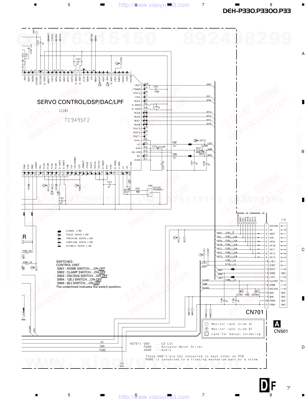
 "先锋PIONEER DEH-P3300X1MUC1电路图-8")
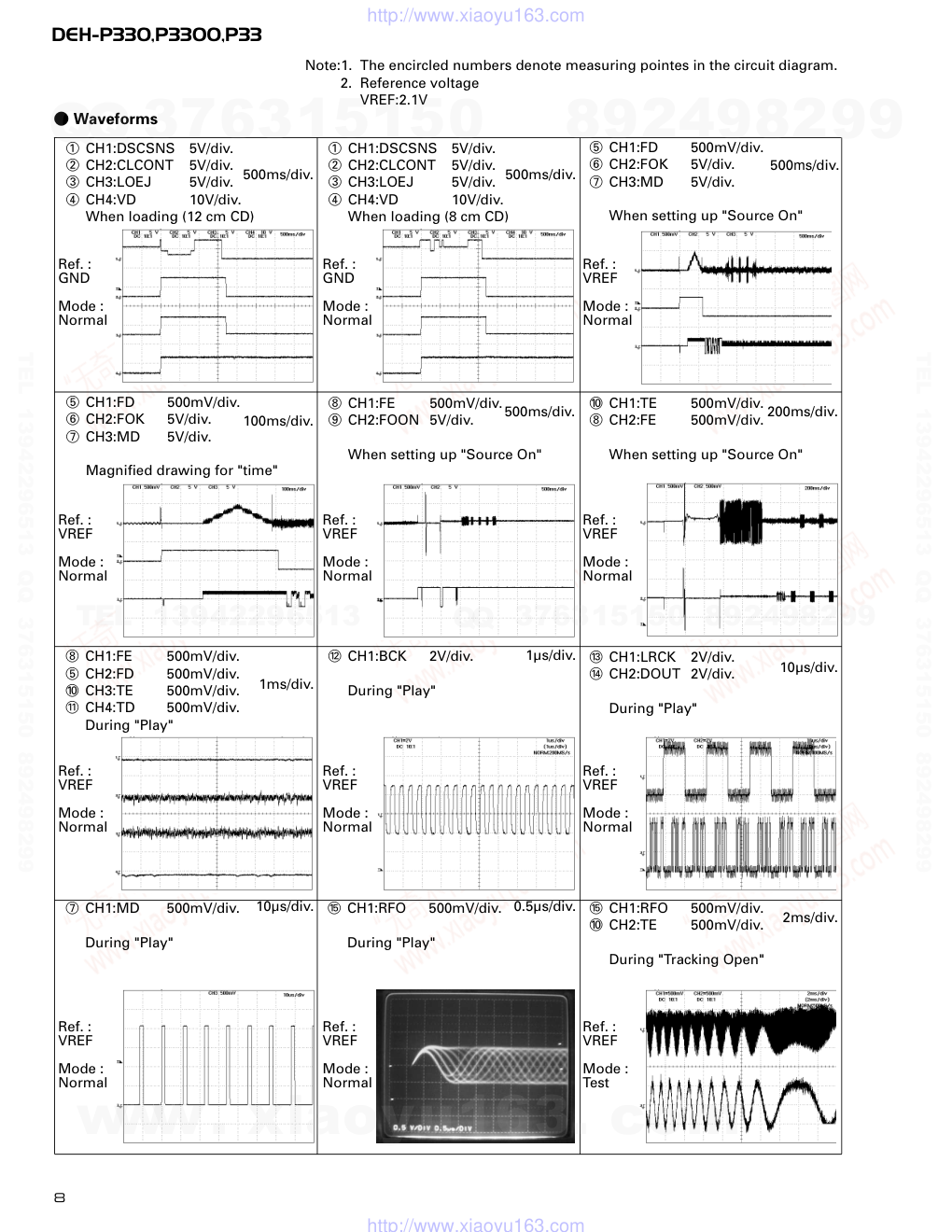
 "先锋PIONEER DEH-P3300X1MUC1电路图-9")
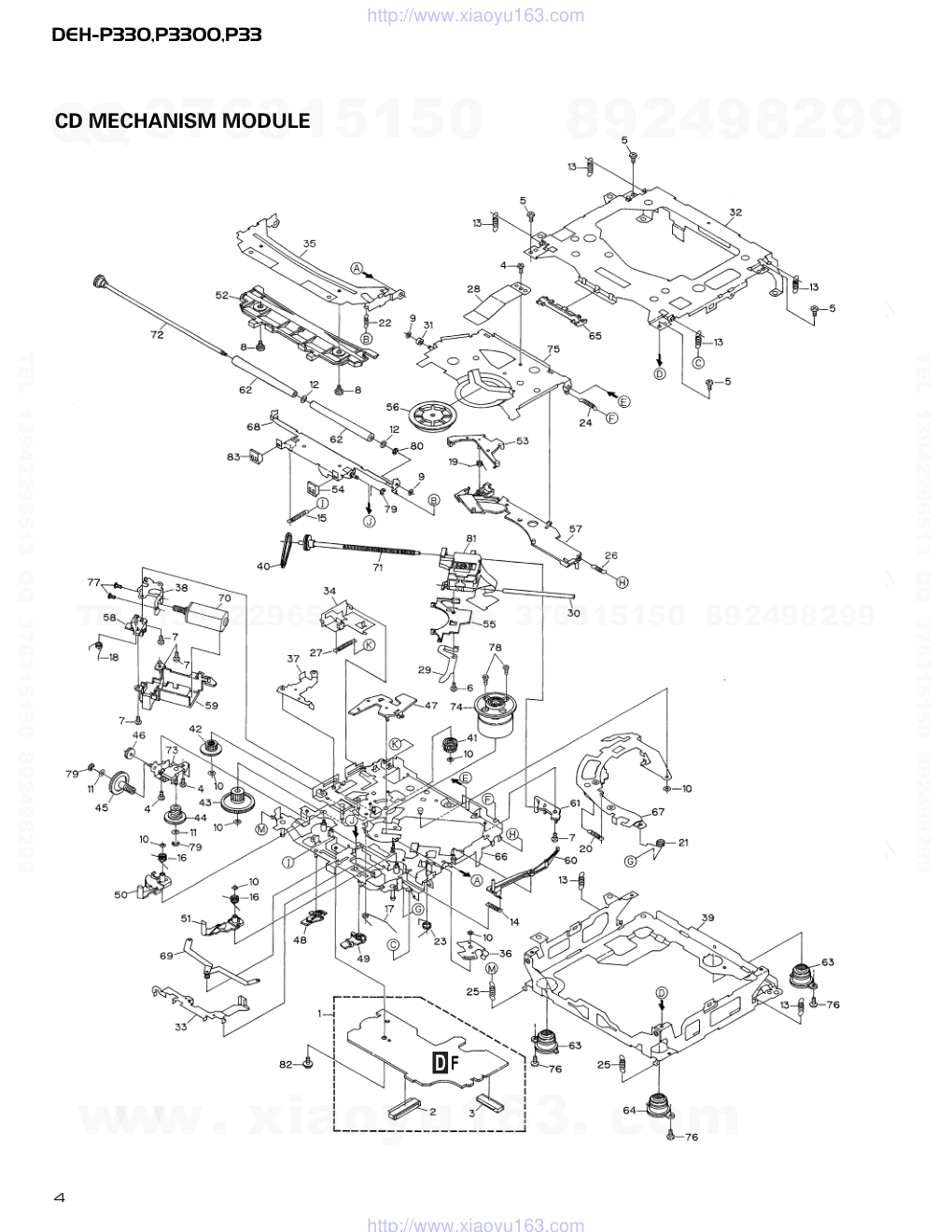
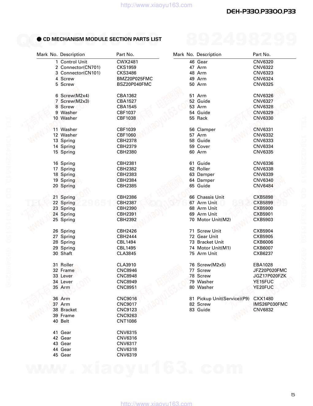
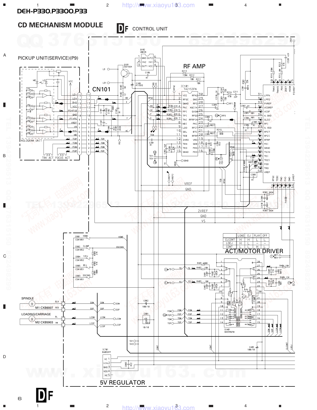
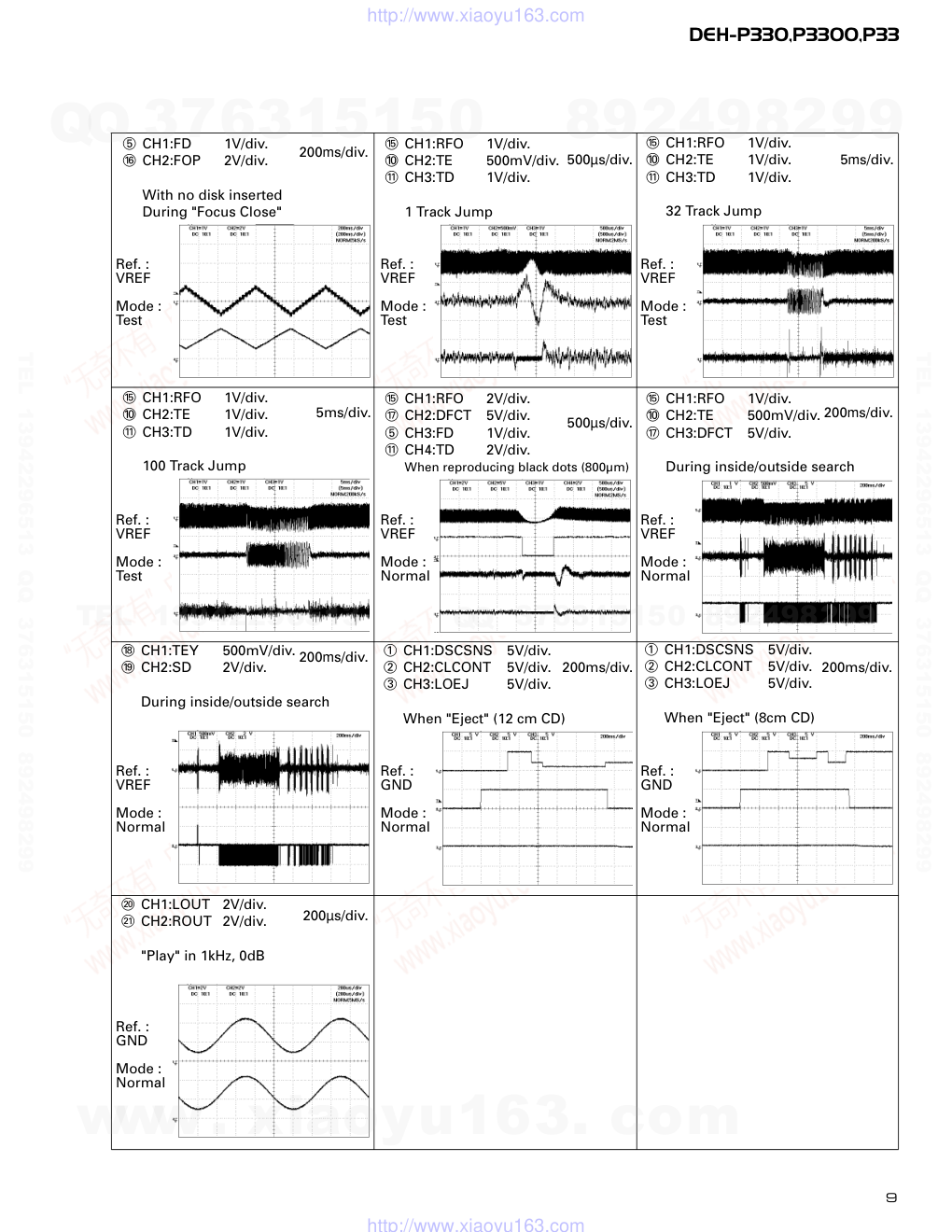
PIONEER CORPORATION 4-1, Meguro 1-Chome, Meguro-ku, Tokyo 153-8654, Japan PIONEER ELECTRONICS SERVICE INC. P.O.Box 1760, Long Beach, CA 90801-1760 U.S.A. PIONEER EUROPE NV Haven 1087 Keetberglaan 1, 9120 Melsele, Belgium PIONEER ELECTRONICS ASIACENTRE PTE.LTD. 253 Alexandra Road, #04-01, Singapore 159936 C PIONEER CORPORATION 2001 K-ZZU. MAR. 2001 Printed in Japan ORDER NO. CRT2666 Service Manual HIGH POWER CD PLAYER WITH FM/AM TUNER DEH-P330 X1N/UC1,X1M/UC1 DEH-P3300 X1N/UC1,X1M/UC1 DEH-P33 X1N/UC1,X1M/UC1 (Service's No. :DEH-P330-2/X1N/UC,X1M/UC1) (Service's No. :DEH-P3300-2/X1N/UC,X1M/UC1) (Service's No. :DEH-P33-2/X1N/UC,X1M/UC1) - This is the unit which has been replaced S8.1(CXK5201) CD mechanism module with S9(CXK5500). - This service manual should be used together with the manual(s) listed below. For the parts numbers, adjustments, etc. which are not shown in this manual, refer to the following manual(s). Model No. Order No. Mech. Module Remarks CX-977 CRT2624 S9 CD Mech. Module:Circuit Description, Mech. Description, Disassembly DEH-P330/X1N/UC CRT2575 - CD Player Service Precautions 1. For pickup unit(CXX1480) handling, please refer to"Disassembly"(see page 22). During replacement, handling precautions shall be taken to prevent an electrostatic discharge(protection by a jumper-solder). 2. During disassembly, be sure to turn the power off since an internal IC might be destroyed when a con- nector is plugged or unplugged. 3. Please checking the grating after changing the ser- vice pickup unit(see page 16). www. xiaoyu163. com QQ 376315150 9 9 2 8 9 4 2 9 8 TEL 13942296513 9 9 2 8 9 4 2 9 8 0 5 1 5 1 3 6 7 3 Q Q TEL 13942296513 QQ 376315150 892498299 TEL 13942296513 QQ 376315150 892498299 http://www.xiaoyu163.com DEH-P330,P3300,P33 EXPLODED VIEWS AND PARTS LIST PACKING (Page 3) - PACKING SECTION PARTS LIST Part No. Mark No. Description DEH-P330/X1N/UC DEH-P330/X1N/UC1 DEH-P330/X1M/UC1 13 Carton CHG4273 CHG4365 CHG4378 14 Contain Box CHL4273 CHL4365 CHL4378 - PACKING SECTION PARTS LIST Part No. Mark No. Description DEH-P3300/X1N/UC DEH-P3300/X1N/UC1 DEH-P3300/X1M/UC1 13 Carton CHG4272 CHG4364 CHG4377 14 Contain Box CHL4272 CHL4364 CHL4377 - PACKING SECTION PARTS LIST Part No. Mark No. Description DEH-P33/X1N/UC DEH-P33/X1N/UC1 DEH-P33/X1M/UC1 13 Carton CHG4274 CHG4366 CHG4379 14 Contain Box CHL4274 CHL4366 CHL4379 EXTERIOR (Page 5) - EXTERIOR SECTION PARTS LIST Part No. Mark No. Description DEH-P330/X1N/UC DEH-P330/X1N/UC1,X1M/UC1 6 Cable CDE6444 CDE6610 14 Tuner Amp Unit CWM7388 CWM7847 22 Connector(CN501) CKS4398 CKS3835 79 CD Mechanism Module CXK5201(S8.1) CXK5500(S9) - EXTERIOR SECTION PARTS LIST Part No. Mark No. Description DEH-P3300/X1N/UC DEH-P3300/X1N/UC1,X1M/UC1 6 Cable CDE6444 CDE6610 14 Tuner Amp Unit CWM7385 CWM7844 22 Connector(CN501) CKS4398 CKS3835 79 CD Mechanism Module CXK5201(S8.1) CXK5500(S9) - EXTERIOR SECTION PARTS LIST Part No. Mark No. Description DEH-P33/X1N/UC DEH-P33/X1N/UC1,X1M/UC1 6 Cable CDE6444 CDE6610 14 Tuner Amp Unit CWM7387 CWM7846 22 Connector(CN501) CKS4398 CKS3835 79 CD Mechanism Module CXK5201(S8.1) CXK5500(S9) SAFETY INFORMATION This service manual is intended for qualified service technicians; it is not meant for the casual do-it-yourselfer. Qualified technicians have the necessary test equipment and tools, and have been trained to properly and safely repair complex products such as those covered by this manual. Improperly performed repairs can adversely affect the safety and reliability of the product and may void the warranty. If you are not qualified to perform the repair of this product properly and safely; you should not risk trying to do so and refer the repair to a qualified service technician. www. xiaoyu163. com QQ 376315150 9 9 2 8 9 4 2 9 8 TEL 13942296513 9 9 2 8 9 4 2 9 8 0 5 1 5 1 3 6 7 3 Q Q TEL 13942296513 QQ 376315150 892498299 TEL 13942296513 QQ 376315150 892498299 http://www.xiaoyu163.com 3 DEH-P330,P3300,P33 ELECTRICAL PARTS LIST(Page 36) Tuner Amp Unit Part No. DEH-P330/X1N/UC DEH-P330/X1N/UC1,X1M/UC1 DEH-P3300/X1N/UC DEH-P3300/X1N/UC1,X1M/UC1 Circuit Symbol and No. DEH-P33/X1N/UC DEH-P33/X1N/UC1,X1M/UC1 IC601 PE5203A PE5246A X610(12.58921MHz) CSS1495 CSS1402 R514,R515 RS1/16S473J Not used R516 RS1/16S473J RS1/16S104J R518 RS1/16S222J Not used R519 RS1/16S222J RS1/16S102J R520 RS1/16S681J RS1/16S0R0J R521 RS1/16S102J RS1/16S222J R522,R524,R534,R535 RS1/16S0R0J Not used R523 RS1/16S102J RS1/16S0R0J R525,R526,R527 Not used RS1/16S222J R529 Not used RS1/4PU0R0J R530 Not used RS1/16S0R0J R536 RS1/16S0R0J RS1/16S102J R537 Not used RS1/16S104J R621 RS1/16S331J RS1/16S0R0J C616 CCSRCH270J50 CCSRCH200J50 C617 CSSRCH330J50 CSSRCH200J50 CN701 D CONTROL UNIT 104 (1/4W) 104 F www. xiaoyu163. com QQ 376315150 9 9 2 8 9 4 2 9 8 TEL 13942296513 9 9 2 8 9 4 2 9 8 0 5 1 5 1 3 6 7 3 Q Q TEL 13942296513 QQ 376315150 892498299 TEL 13942296513 QQ 376315150 892498299 http://www.xiaoyu163.com 4 DEH-P330,P3300,P33 CD MECHANISM MODULE D F www. xiaoyu163. com QQ 376315150 9 9 2 8 9 4 2 9 8 TEL 13942296513 9 9 2 8 9 4 2 9 8 0 5 1 5 1 3 6 7 3 Q Q TEL 13942296513 QQ 376315150 892498299 TEL 13942296513 QQ 376315150 892498299 http://www.xiaoyu163.com DEH-P330,P3300,P33 5 Mark No. Description Part No. Mark No. Description Part No. 1 Control Unit CWX2481 2 Connector(CN701) CKS1959 3 Connector(CN101) CKS3486 4 Screw BMZ20P025FMC 5 Screw BSZ20P040FMC 6 Screw(M2x4) CBA1362 7 Screw(M2x3) CBA1527 8 Screw CBA1545 9 Washer CBF1037 10 Washer CBF1038 11 Washer CBF1039 12 Washer CBF1060 13 Spring CBH2378 14 Spring CBH2379 15 Spring CBH2380 16 Spring CBH2381 17 Spring CBH2382 18 Spring CBH2383 19 Spring CBH2384 20 Spring CBH2385 21 Spring CBH2386 22 Spring CBH2387 23 Spring CBH2390 24 Spring CBH2391 25 Spring CBH2392 26 Spring CBH2426 27 Spring CBH2444 28 Spring CBL1494 29 Spring CBL1495 30 Shaft CLA3845 31 Roller CLA3910 32 Frame CNC8946 33 Lever CNC8948 34 Lever CNC8949 35 Arm CNC8951 36 Arm CNC9016 37 Arm CNC9017 38 Bracket CNC9123 39 Frame CNC9263 40 Belt CNT1086 41 Gear CNV6315 42 Gear CNV6316 43 Gear CNV6317 44 Gear CNV6318 45 Gear CNV6319 46 Gear CNV6320 47 Arm CNV6322 48 Arm CNV6323 49 Arm CNV6324 50 Arm CNV6325 51 Arm CNV6326 52 Guide CNV6327 53 Arm CNV6328 54 Guide CNV6329 55 Rack CNV6330 56 Clamper CNV6331 57 Arm CNV6332 58 Guide CNV6333 59 Cover CNV6334 60 Arm CNV6335 61 Guide CNV6336 62 Roller CNV6338 63 Damper CNV6339 64 Damper CNV6340 65 Guide CNV6484 66 Chassis Unit CXB5898 67 Arm Unit CXB5899 68 Arm Unit CXB5900 69 Arm Unit CXB5901 70 Motor Unit(M2) CXB5903 71 Screw Unit CXB5904 72 Gear Unit CXB5905 73 Bracket Unit CXB6006 74 Motor Unit(M1) CXB6007 75 Arm Unit CXB6237 76 Screw(M2x5) EBA1028 77 Screw JFZ20P020FMC 78 Screw JGZ17P020FZK 79 Washer YE15FUC 80 Washer YE20FUC 81 Pickup Unit(Service)(P9) CXX1480 82 Screw IMS26P030FMC 83 Guide CNV6832 - CD MECHANISM MODULE SECTION PARTS LIST www. xiaoyu163. com QQ 376315150 9 9 2 8 9 4 2 9 8 TEL 13942296513 9 9 2 8 9 4 2 9 8 0 5 1 5 1 3 6 7 3 Q Q TEL 13942296513 QQ 376315150 892498299 TEL 13942296513 QQ 376315150 892498299 http://www.xiaoyu163.com D F 6 DEH-P330,P3300,P33 1 2 3 4 1 2 3 4 D C B A CD MECHANISM MODULE M1 CXB6007 M2 CXB5903 LOADING/CARRIAGE SPINDLE RF AMP S ACT/MOTOR DRIVER 5V REGULATOR CN101 CONTROL UNIT PICKUP UNIT(SERVICE)(P9) D F www. xiaoyu163. com QQ 376315150 9 9 2 8 9 4 2 9 8 TEL 13942296513 9 9 2 8 9 4 2 9 8 0 5 1 5 1 3 6 7 3 Q Q TEL 13942296513 QQ 376315150 892498299 TEL 13942296513 QQ 376315150 892498299 http://www.xiaoyu163.com D DEH-P330,P3300,P33 5 6 7 8 5 6 7 8 D C B A 7 16.934MHz SERVO CONTROL/DSP/DAC/LPF ER CN701 SWITCHES: CONTROL UNIT S901 : HOME SWITCH.....ON-OFF S902 : CLAMP SWITCH....ON-OFF S903 : DSCSNS SWITCH....ON-OFF S904 : 12EJ SWITCH....ON-OFF S905 : 8EJ SWITCH....ON-OFF The underlined indicates the switch position. A CN501 F www. xiaoyu163. com QQ 376315150 9 9 2 8 9 4 2 9 8 TEL 13942296513 9 9 2 8 9 4 2 9 8 0 5 1 5 1 3 6 7 3 Q Q TEL 13942296513 QQ 376315150 892498299 TEL 13942296513 QQ 376315150 892498299 http://www.xiaoyu163.com 8 DEH-P330,P3300,P33 @ CH1:BCK 2V/div. During "Play" 1 CH1:DSCSNS 5V/div. 2 CH2:CLCONT 5V/div. 3 CH3:LOEJ 5V/div. 4 CH4:VD 10V/div. When loading (8 cm CD) 500ms/div. 5 CH1:FD 500mV/div. 6 CH2:FOK 5V/div. 7 CH3:MD 5V/div. When setting up "Source On" 500ms/div. 8 CH1:FE 500mV/div. 9 CH2:FOON 5V/div. When setting up "Source On" 500ms/div. 5 CH1:FD 500mV/div. 6 CH2:FOK 5V/div. 7 CH3:MD 5V/div. Magnified drawing for "time" 100ms/div. 1 CH1:DSCSNS 5V/div. 2 CH2:CLCONT 5V/div. 3 CH3:LOEJ 5V/div. 4 CH4:VD 10V/div. When loading (12 cm CD) Ref. : GND Mode : Normal Ref. : GND Mode : Normal Ref. : VREF Mode : Normal Ref. : VREF Mode : Normal Ref. : VREF Mode : Normal Ref. : VREF Mode : Normal Ref. : VREF Mode : Normal Ref. : VREF Mode : Normal Ref. : VREF Mode : Normal Ref. : VREF Mode : Test Ref. : VREF Mode : Normal Ref. : VREF Mode : Normal 500ms/div. 0 CH1:TE 500mV/div. 8 CH2:FE 500mV/div. When setting up "Source On" 200ms/div. 1µs/div. # CH1:LRCK 2V/div. $ CH2:DOUT 2V/div. During "Play" 10µs/div. 7 CH1:MD 500mV/div. During "Play" 10µs/div. % CH1:RFO 500mV/div. During "Play" 0.5µs/div. % CH1:RFO 500mV/div. 0 CH2:TE 500mV/div. During "Tracking Open" 2ms/div. 8 CH1:FE 500mV/div. 5 CH2:FD 500mV/div. 0 CH3:TE 500mV/div. ! CH4:TD 500mV/div. During "Play" 1ms/div. - Waveforms Note:1. The encircled numbers denote measuring pointes in the circuit diagram. 2. Reference voltage VREF:2.1V www. xiaoyu163. com QQ 376315150 9 9 2 8 9 4 2 9 8 TEL 13942296513 9 9 2 8 9 4 2 9 8 0 5 1 5 1 3 6 7 3 Q Q TEL 13942296513 QQ 376315150 892498299 TEL 13942296513 QQ 376315150 892498299 http://www.xiaoyu163.com DEH-P330,P3300,P33 9 % CH1:RFO 1V/div. 0 CH2:TE 500mV/div. & CH3:DFCT 5V/div. During inside/outside search 200ms/div. % CH1:RFO 1V/div. 0 CH2:TE 500mV/div. ! CH3:TD 1V/div. 1 Track Jump 500µs/div. % CH1:RFO 1V/div. 0 CH2:TE 1V/div. ! CH3:TD 1V/div. 100 Track Jump 5ms/div. % CH1:RFO 1V/div. 0 CH2:TE 1V/div. ! CH3:TD 1V/div. 32 Track Jump 5ms/div. 5 CH1:FD 1V/div. ^ CH2:FOP 2V/div. With no disk inserted During "Focus Close" 200ms/div. 1 CH1:DSCSNS 5V/div. 2 CH2:CLCONT 5V/div. 3 CH3:LOEJ 5V/div. When "Eject" (8cm CD) 200ms/div. ) CH1:LOUT 2V/div. ⁄ CH2:ROUT 2V/div. "Play" in 1kHz, 0dB 200µs/div. * CH1:TEY 500mV/div. ( CH2:SD 2V/div. During inside/outside search 200ms/div. 1 CH1:DSCSNS 5V/div. 2 CH2:CLCONT 5V/div. 3 CH3:LOEJ 5V/div. When "Eject" (12 cm CD) 200ms/div. % CH1:RFO 2V/div. & CH2:DFCT 5V/div. 5 CH3:FD 1V/div. ! CH4:TD 2V/div. When reproducing black dots (800µm) 500µs/div. Ref. : VREF Mode : Test Ref. : VREF Mode : Test Ref. : VREF Mode : Normal Ref. : VREF Mode : Normal Ref. : VREF Mode : Test Ref. : VREF Mode : Test Ref. : VREF Mode : Normal Ref. : GND Mode : Normal Ref. : GND Mode : Normal Ref. : GND Mode : Normal www. xiaoyu163. com QQ 376315150 9 9 2 8 9 4 2 9 8 TEL 13942296513 9 9 2 8 9 4 2 9 8 0 5 1 5 1 3 6 7 3 Q Q TEL 13942296513 QQ 376315150 892498299 TEL 13942296513 QQ 376315150 892498299 http://www.xiaoyu163.com 10 DEH-P330,P3300,P33 1 2 3 4 1 2 3 4 D C B A CD MECHANISM MODULE CONTROL UNIT SIDE A VREF E F HOME 12EJ DSCSNS M2 LOADING/CARRIAGE MOTOR M1 SPINDLE MOTOR PICKUP UNIT(SERVICE)(P9) A CN501 D F D F www. xiaoyu163. com QQ 376315150 9 9 2 8 9 4 2 9 8 TEL 13942296513 9 9 2 8 9 4 2 9 8 0 5 1 5 1 3 6 7 3 Q Q TEL 13942296513 QQ 376315150 892498299 TEL 13942296513 QQ 376315150 892498299 http://www.xiaoyu163.com DEH-P330,P3300,P33 1 2 3 4 1 2 3 4 D C B A 11 SIDE B CONTROL UNIT CLAMP 8EJ D F D F www. xiaoyu163. com QQ 376315150 9 9 2 8 9 4 2 9 8 TEL 13942296513 9 9 2 8 9 4 2 9 8 0 5 1 5 1 3 6 7 3 Q Q TEL 13942296513 QQ 376315150 892498299 TEL 13942296513 QQ 376315150 892498299 http://www.xiaoyu163.com 12 DEH-P330,P3300,P33 ELECTRICAL PARTS LIST NOTES: - Parts whose parts numbers are omitted are subject to being not supplied. - The part numbers shown below indicate chip components. Chip Resistor RS1/_S___J,RS1/__S___J Chip Capacitor (except for CQS.....) CKS....., CCS....., CSZS..... =====Circuit Symbol and No.===Part Name Part No. --- ------ ------------------------------------------ ------------------------- Unit Number : CWX2481 Unit Name : Control Unit MISCELLANEOUS IC 101 IC TA2153FN IC 201 IC TC9495F2 IC 401 IC BA5996FM IC 701 IC BA05SFP Q 101 Transistor 2SD1664 Q 102 Transistor UMD2N L 201 Inductor CTF1546 L 202 Inductor CTF1546 X 301 Ceramic Resonator 16.934MHz CSS1525 S 901 Spring Switch(HOME) CSN1051 S 902 Spring Switch(CLAMP) CSN1052 S 903 Spring Switch(DSCSNS) CSN1051 S 904 Spring Switch(12EJ) CSN1052 S 905 Spring Switch(8EJ) CSN1051 RESISTORS R 101 RS1/16S222J R 102 RS1/8S120J R 103 RS1/8S100J R 201 RS1/16S513J R 202 RS1/16S513J R 203 RS1/16S823J R 204 RS1/16S823J R 206 RS1/16S823J R 208 RS1/16S124J R 209 RS1/16S183J R 210 RS1/16S153J R 211 RS1/16S103J R 212 RS1/16S103J R 213 RS1/16S124J R 215 RS1/16S0R0J R 216 RS1/16S471J R 301 RS1/16S333J R 302 RS1/16S332J R 303 RS1/16S332J R 304 RS1/16S514J R 306 RS1/16S102J R 307 RS1/16S102J R 312 RS1/16S103J R 313 RS1/16S473J R 315 RD1/4PU334J R 321 RS1/16S331J R 322 RS1/16S0R0J R 323 RS1/16S332J R 401 RS1/16S684J R 402 RS1/16S103J R 403 RS1/16S103J R 404 RS1/16S183J R 405 RS1/16S123J R 407 RS1/16S622J R 408 RS1/16S622J R 409 RS1/16S113J R 410 RS1/16S752J R 701 RS1/16S102J R 702 RS1/16S221J R 703 RS1/16S221J R 704 RS1/16S221J R 705 RS1/16S221J R 706 RS1/16S221J R 707 RS1/16S221J R 708 RS1/16S102J R 709 RS1/16S102J R 710 RS1/16S102J R 901 RS1/16S104J R 902 RS1/16S473J R 903 RS1/16S273J CAPACITORS C 101 CEV470M6R3 C 102 CKSRYB102K50 C 103 CKSRYB104K16 C 104 CKSRYB224K16 C 105 CEV470M6R3 C 106 CKSRYB104K16 C 107 CKSRYB105K6R3 C 201 CKSRYB104K16 C 202 CCSRCH560J50 C 204 CKSRYB224K16 C 205 CKSRYB224K16 C 206 CKSRYB273K25 C 207 CKSRYB273K25 C 208 CKSRYB104K16 C 209 CKSRYB104K16 C 210 CCSRCK2R0C50 C 211 CCSRCH220J50 C 301 CKSRYB153K25 C 302 CKSRYB104K16 C 303 CKSRYB103K50 C 304 CKSRYB103K50 C 305 CKSRYB104K16 C 306 CKSRYB104K16 C 307 CKSRYB333K16 C 308 CKSRYB104K16 C 309 CKSRYB473K16 C 310 CKSRYB473K16 C 311 CKSRYB104K16 C 312 CKSRYB104K16 C 315 CEV220M6R3 C 317 CKSRYB104K16 C 318 CKSRYB104K16 C 319 CKSRYB104K16 C 320 CCSRCH470J50 C 325 CKSRYB471K50 =====Circuit Symbol and No.===Part Name Part No. --- ------ ------------------------------------------ ------------------------- D F www. xiaoyu163. com QQ 376315150 9 9 2 8 9 4 2 9 8 TEL 13942296513 9 9 2 8 9 4 2 9 8 0 5 1 5 1 3 6 7 3 Q Q TEL 13942296513 QQ 376315150 892498299 TEL 13942296513 QQ 376315150 892498299 http://www.xiaoyu163.com DEH-P330,P3300,P33 13 C 328 CKSRYB472K50 C 329 CKSRYB104K16 C 330 CKSRYB104K16 C 331 CKSRYB104K16 C 401 CKSRYB221K50 C 402 CKSRYB221K50 C 403 CKSRYB153K25 C 404 CKSRYB103K50 C 405 CEV101M10 C 702 CKSRYB104K16 C 703 CKSRYB104K16 C 801 10µF/10V CCH1349 C 802 CEV101M10 C 803 CKSRYB224K16 Miscellaneous Parts List Pickup Unit(Service)(P9) CXX1480 M 1 Motor Unit(SPINDLE) CXB6007 M 2 Motor Unit(LOADING/CARRIAGE) CXB5903 =====Circuit Symbol and No.===Part Name Part No. --- ------ ------------------------------------------ ------------------------- www. xiaoyu163. com QQ 376315150 9 9 2 8 9 4 2 9 8 TEL 13942296513 9 9 2 8 9 4 2 9 8 0 5 1 5 1 3 6 7 3 Q Q TEL 13942296513 QQ 376315150 892498299 TEL 13942296513 QQ 376315150 892498299 http://www.xiaoyu163.com 14 DEH-P330,P3300,P33 CD ADJUSTMENT 1) Precautions • This unit uses a single power supply (+5V) for the reg- ulator. The signal reference potential, therefore, is connected to VREF(approx. 2.1V) instead of GND. If VREF and GND are connected to each other by mis- take during adjustments, not only will it be impossi- ble to measure the potential correctly, but the servo will malfunction and a severe shock will be applied to the pick-up. To avoid this, take special note of the fol- lowing. Do not connect the negative probe of the measuring equipment to VREF and GND together. It is especially important not to connect the channel 1 negative probe of the oscilloscope to VREF with the channel 2 negative probe connected to GND. Since the frame of the measuring instrument is usual- ly at the same potential as the negative probe, change the frame of the measuring instrument to floating sta- tus. If by accident VREF comes in contact with GND, immediately switch the regulator or power OFF. • Always make sure the regulator is OFF when connect- ing and disconnecting the various filters and wiring required for measurements. • Before proceeding to further adjustments and mea- surements after switching regulator ON, let the player run for about one minute to allow the circuits to stabi- lize. • Since the protective systems in the unit's software are rendered inoperative in test mode, be very careful to avoid mechanical and /or electrical shocks to the sys- tem when making adjustment. • The RFI and RFO signals are easy to oscillate because of a wide band. When observing them, insert a resis- tor of about 1 kΩ to the series. • This equipment will not guarantee the load ejection operation when the mechanical unit is turned upside down. In particular, if the ejection operation is incor- rectly performed and recovery is disabled, the recov- ery is enabled by resetting a product or turning ACC off to on. 2) Test Mode This mode is used for adjusting the CD mechanism module of the device. • Test mode starting procedure Reset while pressing the 4 and 6 keys together. • Test mode cancellation Switch ACC, back-up OFF. • After pressing the EJECT key, do not press any other key until the disk is completely ejected. • If the ] or [ key is pressed while focus search is in progress, immediately turn the power off (otherwise the actuator may be damaged due to adhesion of the lenses). • Jump operation of TRs other than 100TR continues after releasing the key. CRG move and 100TR jump operations are brought into the “Tracking close” sta- tus when the key is released. • Powering Off/On resets the jump mode to “Single TR(91)”, the RF AMP gain setting to 0 dB, and the automatic adjustment value to the initial value. www. xiaoyu163. com QQ 376315150 9 9 2 8 9 4 2 9 8 TEL 13942296513 9 9 2 8 9 4 2 9 8 0 5 1 5 1 3 6 7 3 Q Q TEL 13942296513 QQ 376315150 892498299 TEL 13942296513 QQ 376315150 892498299 http://www.xiaoyu163.com DEH-P330,P3300,P33 15 *1) +12dB TRK12 MIN12 SEC12 TYP TRK MIN SEC *2) S. curve check setting TRK01 MIN01 SEC01 Focus Close setting TRK00 MIN00 SEC00 or TRK99 MIN99 SEC99 *8) CRG motor voltage = 2 [V] *3) T.Offset Display Switch to the order of the original display F.Offset Display *7) F.AGC Gain RF AGC Gain TRK/MIN/SEC T.AGC Gain *5 Single TR TRK91 MIN91 SEC91 or TRK81 MIN81 SEC81 32TR TRK92 MIN92 SEC92 or TRK82 MIN82 SEC82 100TR TRK93 MIN93 SEC93 or TRK83 MIN83 SEC83 CRG Move TRK94 MIN94 SEC94 or TRK84 MIN84 SEC84 *4) 1TR/32TR/100TR *6) Only at the time of CRG move or 100TR jump [BAND] Power On (T. offset is adjusted) TRK00 MIN00 SEC00 [CD] or [SOURCE] Source On TRK MIN [4]+[6]+Reset Test Mode In [3] Power On (T. offset is not adjusted) TRK99 MIN99 SEC99 [2] RF AMP Gain switching*1 TRKGG MINGG SECGG [BAND] Power Off TRK MIN SEC [BAND] Power Off TRK MIN SEC [BAND] Power Off TRK MIN SEC [BAND] Power Off TRK MIN SEC [3] Focus Close / S. curve check TRK91 MIN91 SEC91 [6] Focus Mode switching*2 TRK0x MIN0x SEC0x [1] Tracking Servo Close TRK00 MIN00 SEC00 or TRK99 MIN99 SEC99 [[] CRG- *8 TRK00 MIN00 SEC00 or TRK99 MIN99 SEC99 []] CRG+ *8 TRK00 MIN00 SEC00 or TRK99 MIN99 SEC99 [6] New Test Mode [2] Automatic adjustment value display switching *3 TRK?? MIN?? SEC?? [1] T.CLS and F,T AGC and RF AGC and Applicable servomechanism TRKxx MINxx SECxx [6] T.Close and Applicable servomechanism TRKxx MINxx SECxx [3] RF AGC / RF AGC coefficient display TRK?? MIN?? SEC?? []] CRG+ TRK8x MIN8x SEC8x or TRK9x MIN9x SEC9x [[] CRG- TRK8x MIN8x SEC8x or TRK9x MIN9x SEC9x [2] T.Balance adjustment / T.Balance coefficient display TRK?? MIN?? SEC?? [1] F,T,RF AGC / F.Bias display switching*7 TRK?? MIN?? SEC?? [3] F,T AGC,F.Bias and RF AGC TRKxx MINxx SECxx [6] CRG/TR jump value *5 switching TRKxx MINxx SECxx []] CRG+/TR Jump+ *4 TRKxx MINxx SECxx [[] CRG-/TR Jump- *4 TRK xx MINxx SEC xx [2] Tracking Open TRK8x MIN8x SEC8x or TRK9x MIN9x SEC9x [2] Tracking Open TRK8x MIN8x SEC8x or TRK9x MIN9x SEC9x F. EQ measurement setting TRK02 MIN02 SEC02 [Key] [BAND] []] [[] [1] [2] [3] [6] - - Power On/Off CRG +/TR Jump+ (Direction of the external surface) CRG -/TR Jump- (Direction of the internal surface) T.CLS and AGC and Applicable servomechanism/ AGC,AGC display switching RF Gain switching/Offset adjustment display/ T.Balance adjustment/T.OPN F.CLS,S.Curve/Rough Servo and RF AGC/ F,T,RF AGC SPDL 1X/2X switching (Double-speed compatibility only) Error rate measurement F.Mode switching/T.CLS/CRG,TR Jump switching Test Mode New Test Mode Operation Error occurrence time/ cause display switching TRK+/FF TRK-/REV SCAN MODE (ITP) - - Auto/Manual switching F.Bias [KEY] Contents Display - Flow Chart www. xiaoyu163. com QQ 376315150 9 9 2 8 9 4 2 9 8 TEL 13942296513 9 9 2 8 9 4 2 9 8 0 5 1 5 1 3 6 7 3 Q Q TEL 13942296513 QQ 376315150 892498299 TEL 13942296513 QQ 376315150 892498299 http://www.xiaoyu163.com 16 DEH-P330,P3300,P33 • Note : The grating angle of the PU unit cannot be adjusted after the PU unit is changed. The PU unit in the CD mecha- nism module is adjusted on the production line to match the CD mechanism module and is thus the best adjusted PU unit for the CD mechanism module. Changing the PU unit is thus best considered as a last resort. However, if the PU unit must be changed, the grating should be checked using the procedure below. • Purpose : To check that the grating is within an acceptable range when the PU unit is changed. • Symptoms of Mal-adjustment : If the grating is off by a large amount symptoms such as being unable to close tracking, being unable to perform track search operations, or taking a long time for track searching. • Method : • Measuring Equipment • Oscilloscope, Two L.P.F. • Measuring Points • E, F, VREF • Disc • ABEX TCD-784 • Mode • TEST MODE • Checking Procedure 1. In test mode, load the disc and switch the 5V regulator on. 2. Using the ] and [ buttons, move the PU unit to the innermost track. 3. Press key 3 to close focus, the display should read "91". Press key 2 to implement the tracking balance adjust- ment the display should now read "81". Press key 3. The display will change, returning to "81" on the fourth press. 4. As shown in the diagram above, monitor the LPF outputs using the oscilloscope and check that the phase differ- ence is within 75° . Refer to the photographs supplied to determine the phase angle. 5. If the phase difference is determined to be greater than 75° try changing the PU unit to see if there is any improvement. If, after trying this a number of times, the grating angle does not become less than 75° then the mechanism should be judged to be at fault. • Note Because of eccentricity in the disc and a slight misalignment of the clamping center the grating waveform may be seen to "wobble" ( the phase difference changes as the disc rotates). The angle specified above indicates the aver- age angle. • Hint Reloading the disc changes the clamp position and may decrease the "wobble". 100kΩ 390pF 100kΩ 390pF E VREF F VREF Xch Ych L.P.F. L.P.F. VREF E F CHECKING THE GRATING AFTER CHANGING THE PICKUP UNIT CONTROL UNIT Oscilloscope www. xiaoyu163. com QQ 376315150 9 9 2 8 9 4 2 9 8 TEL 13942296513 9 9 2 8 9 4 2 9 8 0 5 1 5 1 3 6 7 3 Q Q TEL 13942296513 QQ 376315150 892498299 TEL 13942296513 QQ 376315150 892498299 http://www.xiaoyu163.com DEH-P330,P3300,P33 17 Grating waveform Ech → Xch 20mV/div, AC Fch → Ych 20mV/div, AC 45° 0° 75° 60° 30° 90° www. xiaoyu163. com QQ 376315150 9 9 2 8 9 4 2 9 8 TEL 13942296513 9 9 2 8 9 4 2 9 8 0 5 1 5 1 3 6 7 3 Q Q TEL 13942296513 QQ 376315150 892498299 TEL 13942296513 QQ 376315150 892498299 http://www.xiaoyu163.com 18 DEH-P330,P3300,P33 GENERAL INFORMATION TEST MODE - Error Messages If a CD is not operative or stopped during operation due to an error, the error mode is turned on and cause(s) of the error is indicated with a corresponding number. This arrangement is intended at reducing nonsense calls from the users and also for facilitating trouble analysis and repair work in servicing. (1) Basic Indication Method 1) When SERRORM is selected for the CSMOD (CD mode area for the system), error codes are written to DMIN (min- utes display area) and DSEC (seconds display area). The same data is written to DMIN and DSEC. DTNO remains in blank as before. 2) Head unit display examples Depending on display capability of LCD used, display will vary as shown below. xx contains the error number. 8-digit display 6-digit display 4-digit display ERROR–xx ERR–xx E–xx (2) Error Code List Code Class Displayed error code Description of the code and potential cause(s) 10 Electricity Carriage Home NG CRG can't be moved to inner diameter. SERVO LSI Com- CRG can't be moved from inner diameter. munication Error → Failure on home switch or CRG move mechanism. Communication error between microcomputer and SERVO LSI. 11 Electricity Focus Servo NG Focusing not available. → Stains on rear side of disc or excessive vibrations on REWRITABLE. 12 Electricity Spindle Lock NG Spindle not locked. Sub-code is strange (not readable). Subcode NG → Failure on spindle, stains or damages on disc, or excessive vibrations. A disc not containing CD-R data is found. Turned over disc are found, though rarely. CD signal error. 17 Electricity Setup NG AGC protection doesn't work. Focus can be easily lost. → Damages or stains on disc, or excessive vibrations on REWRITABLE. 30 Electricity Search Time Out Failed to reach target address. → CRG tracking error or damages on disc. 44 Electricity ALL Skip Skip setting for all track. (CD-R/RW) 50 Mechanism CD On Mech Error Mechanical error during CD ON. → Defective loading motor, mechanical lock and mechanical sensor. A0 System Power Supply NG Power (VD) is ground faulted. → Failure on SW transistor or power supply (failure on connector). Remarks: Mechanical errors are not displayed (because a CD is turned off in these errors). Unreadable TOC does not constitute an error. An intended operation continues in this case. Upper digits of an error code are subdivided as shown below: 1x: Setup relevant errors, 3x: Search relevant errors, Ax: Other errors. www. xiaoyu163. com QQ 376315150 9 9 2 8 9 4 2 9 8 TEL 13942296513 9 9 2 8 9 4 2 9 8 0 5 1 5 1 3 6 7 3 Q Q TEL 13942296513 QQ 376315150 892498299 TEL 13942296513 QQ 376315150 892498299 http://www.xiaoyu163.com DEH-P330,P3300,P33 19 - New Test Mode S-CD plays the same way as before. If an error such as off focus, spindle unlocking, unreadable sub-code, or sound skipping occurs after setup, its cause and time occurred (in absolute time) are displayed. During setup, operational status of the control software is displayed. These displays and functions are prepared for enhancing aging in the servicing and efficiency of trouble analysis. (1) Shifting to the New Test Mode 1 Turn on the current test mode by starting the reset from the key. 2 Select S-CD for the source through the specified procedure including use of the [SOURCE] key, and inserting the disc. Then, press the [Jump Mode Selector] key while maintaining the regulator turned off. 3 After the above operations, the new test mode remains on irrespective of whether the S-CD is turned on or off. You can reset the new test mode by turning on the reset start. (2) Key Correspondence Key Test mode New test mode Regulator Off Regulator On In-play Error Production BAND To regulator on To regulator off – Time/Err.No. switching ] – FWD-Kick FF/TR+ – [ – REV-Kick REV/TR- – 1 – Tracking Close Scan – 2 – Tracking Open Mode – 3 – Focus Close – – – – Focus Open – – – – Jump Off – – 6 To new test mode Jump mode switching Auto/Manu – Note: Eject and CD on/off is performed in the same procedure as that for the normal mode. (3) Cause of Error and Error Code Code Class Contents Description and cause 40 Electricity Off focus detected. FOK goes low. → Damages/stains on disc, vibrations or failure on servo. 41 Electricity Spindle unlocked. LOCK = Low continued for 150 msec. → Damages/stains on disc, vibrations or failure on servo. 42 Electricity Sub-code unreadable. Sub-code was unreadable for 500 msec. → Damages/stains on disc, vibrations or failure on servo. 43 Electricity Sound skipping detected. Last address memory function was activated. → Damages/stains on disc, vibrations or failure on servo. Note: Mechanical errors during aging are not displayed. www. xiaoyu163. com QQ 376315150 9 9 2 8 9 4 2 9 8 TEL 13942296513 9 9 2 8 9 4 2 9 8 0 5 1 5 1 3 6 7 3 Q Q TEL 13942296513 QQ 376315150 892498299 TEL 13942296513 QQ 376315150 892498299 http://www.xiaoyu163.com 20 DEH-P330,P3300,P33 (4) Display of Operational Status during Setup Status No. Contents Protective action 21 Focus search start Focus search timeout. 22 Focus search 2 Focus search timeout. 23 Focus search 3 Focus search timeout. 24 Focus search 4 Focus search timeout. 25 Focus search(Setup protection) Focus slips off. 26 Focus search(Fast recovery) Focus slips off. 27 RF detection Focus slips off. 28 Spindle rough servocontrol Focus slips off. 29 Tracking balance adjustment start Focus slips off. 30 Tracking balance adjustment 2 Focus slips off. 31 Tracking balance adjustment 3 Focus slips off. 32 Tracking close start(Spindle stationary servocontrol setting) Focus slips off. 33 Tracking close 2 Focus slips off. 34 Tracking close 3 Focus slips off. 35 Focus/Tracking AGC start Focus slips off. 36 Focus/Tracking AGC 2 Focus slips off. 37 Focus/Tracking AGC 3 Focus slips off. 38 Focus/Tracking AGC 4 Focus slips off. 39 Focus/Tracking AGC 5 Focus slips off. 40 Focus/Tracking AGC 6 Focus slips off. 41 Focus/Tracking AGC 7 Focus slips off. 42 Focus/Tracking AGC 8 Focus slips off. 43 FE bias start Focus slips off. 44 FE bias 2 Focus slips off. 45 RF AGC start Focus slips off. 46 RF AGC 2 Focus slips off. 47 Lock check start Focus slips off. 48 Lock is being checked Focus slips off. 49 Subcode check start Focus slips off, spindle lock is not performed. 50 Subcode is being checked Focus slips off, no subcode can be read. www. xiaoyu163. com QQ 376315150 9 9 2 8 9 4 2 9 8 TEL 13942296513 9 9 2 8 9 4 2 9 8 0 5 1 5 1 3 6 7 3 Q Q TEL 13942296513 QQ 376315150 892498299 TEL 13942296513 QQ 376315150 892498299 http://www.xiaoyu163.com DEH-P330,P3300,P33 21 (5) Display Examples 1) During Setup 8-digit display, 6-digit display 4-digit display(Auto setting) 4-digit display(Manual setting) TNO. Min Sec TNO. Min Sec 11 11' 11" 11 11' 11" 2) During Operation (TOC read, TRK search, Play, FF and REV) The same as in the normal mode. 3) When a Protection Error Occurred (A) Error display ((A)←→(B), (C) : BAND key) 8-digit display 6-digit display 4-digit display ERROR-xx ERR-xx E-xx (B) Error occurrence timing display in track no. ((B)←→(C) : Auto/Manual key) 8-digit display, 6-digit display 4-digit display(Auto setting) TNO. Min Sec TNO. 10 40' 05" 10 (C) Error occurrence timing display in absolute time. ((B)←→(C) : Auto/Manual key) 8-digit display, 6-digit display 4-digit display(Manual setting) TNO. Min Sec Min Sec 10 40' 05" 40' 05" www. xiaoyu163. com QQ 376315150 9 9 2 8 9 4 2 9 8 TEL 13942296513 9 9 2 8 9 4 2 9 8 0 5 1 5 1 3 6 7 3 Q Q TEL 13942296513 QQ 376315150 892498299 TEL 13942296513 QQ 376315150 892498299 http://www.xiaoyu163.com 22 DEH-P330,P3300,P33 - How to hold the Mechanical Unit 1.Hold the top and bottom frame. 2.Do not squeeze top frame's front portion too tight, because it is fragile. - How to remove the Top and Bottom Frame 1.When the disk is "clamp" state, unlock Spring A (6 pieces) and Spring B (2 pieces), and unscrew screws (4 pieces). 2.Unlock each 1 of pawl at the both side of the frame, then remove the top frame. 3.Remove the Carriage Mechanical part in such way that; you remove the mechanical part from 3 pieces of Damper while slowly pulling up the part. 4.Now, the top frame has been removed, and under this state, fix the genuine Connector again, and eject the disk. (Caution) When you reassemble the Carriage Mechanical part, apply a bit of alcohol to Dampers. - How to remove the Guide Arm Assy 1.Unlock the spring (1 piece) at the right side of the assembly. 2.Unscrew screws (2 pieces), then remove the Screw Gear Bracket. 3.Shift the Guide Arm Assy to the left and slowly rotate it to the upper direction. 4.When the Guide Arm Assy rotates approximately 45 degree, shift the Assy to the right side direction and remove it. Top Frame Bottom Frame Damper Spring Screw Gear Bracket Guide Arm Assy Carriage Mechanical Part Do not squeeze. DISASSEMBLY www. xiaoyu163. com QQ 376315150 9 9 2 8 9 4 2 9 8 TEL 13942296513 9 9 2 8 9 4 2 9 8 0 5 1 5 1 3 6 7 3 Q Q TEL 13942296513 QQ 376315150 892498299 TEL 13942296513 QQ 376315150 892498299 http://www.xiaoyu163.com DEH-P330,P3300,P33 23 - How to remove the Control Unit 1.Give jumper-solder treatment to the Flexible Wire of the Pickup unit, then remove the wire from the Connector. 2.Remove all 4 points of solder-treatment on the Lead Wire. Also, unscrew the screw(1 piece). 3.Then, Remove the Control unit. (Caution) Be careful not to damage SW when you reassemble the Control Unit into the device. - How to remove the Loading Arm Assy 1.Unlock the spring (1 piece) and remove the E ring (1 piece) of the Fulcrum Shaft. 2.Shift the arm to the left side direction and unlock pins (2 pieces). - How to remove the Pickup Unit 1.Unscrew 2 pieces of screws, then remove the Pulley Cover. 2.Remove the Feed Screw unit from the pawl of the Feed Screw Guide (The pawl is located inside the guide). 3.Remove the belt from the Pulley, then remove the Pickup unit. (Caution) Make sure not to stain the belt with grease when you fix the belt. Control Unit Jumper-Solder Solder Loading Arm Assy Pickup Unit Pulley Cover Feed Screw Guide Belt Grease Application Grease Application www. xiaoyu163. com QQ 376315150 9 9 2 8 9 4 2 9 8 TEL 13942296513 9 9 2 8 9 4 2 9 8 0 5 1 5 1 3 6 7 3 Q Q TEL 13942296513 QQ 376315150 892498299 TEL 13942296513 QQ 376315150 892498299 http://www.xiaoyu163.com 24 DEH-P330,P3300,P33 1 15 16 30 - Pin Functions(TA2153FN) Pin No. Pin Name I/O Function and Operation 1 VCC Power supply voltage terminal 2 RFGC I RF amplitude adjustment control signal terminal 3 GMAD I AGC amplifier frequency characteristic adjustment terminal 4 FNI I Main beam amplifier input terminal 5 FPI I Main beam amplifier input terminal 6 TPI I Sub beam amplifier input terminal 7 TNI I Sub beam amplifier input terminal 8 MDI O Monitor photodiode amplifier input terminal 9 LDO I Laser diode amplifier output terminal 10 SEL I APC circuit ON/OFF signal, LDO terminal control input terminal and bottom and peak detection frequency switching terminals 11 TEB I Tracking error balance adjustment signal input terminal 12 2VRO O Reference voltage (2VRO) output terminal 13 TEN I Tracking error signal generation amplifier reverse phase input terminal 14 TEO O Tracking error signal generation amplifier output terminal 15 SBAD O Sub beam addition signal output terminal 16 FEO O Focus error signal generation amplifier output terminal 17 FEN I Focus error signal generation amplifier reverse phase input terminal 18 SEB I RFRP generation circuit mode switching terminal 19 VRO O Reference voltage (VREF) output terminal 20 RFRP O Signal generation amplifier output terminal for track count 21 BTC I Bottom detection time constant adjustment terminal for RFCT signal generation 22 RFCT O RFRP signal center level output terminal 23 PKC I Peak detection time constant adjustment signal for RFCT signal generation 24 RFRPIN I Signal generation amplifier input terminal for track count 25 RFGO O RF signal amplitude adjustment amplifier output terminal 26 GVSW I AGC, FE or TE amplifier gain switching terminal 27 AGCIN I RF signal amplitude adjustment amplifier input terminal 28 RFO O RF signal generation amplifier output terminal 29 GND I GND terminal 30 RFN2 I RF signal generation amplifier input terminal TA2153FN IC www. xiaoyu163. com QQ 376315150 9 9 2 8 9 4 2 9 8 TEL 13942296513 9 9 2 8 9 4 2 9 8 0 5 1 5 1 3 6 7 3 Q Q TEL 13942296513 QQ 376315150 892498299 TEL 13942296513 QQ 376315150 892498299 http://www.xiaoyu163.com 25 DEH-P330,P3300,P33 - Pin Functions(TC9495F2) Pin No. Pin Name I/O Function and Operation 1 TESTO Test mode terminal 2 hso O Replay speed flag output terminal 3 uhso O Replay speed flag output terminal 4 EMPH O Emphasis flag output terminal for sub code Q data 5 LRCK O Channel clock (44.1 kHz) output terminal 6 VSS Digital ground terminal 7 BCK O Bit clock output terminal 8 AOUT O Digital audio data output terminal 9 DOUT O Digital out output terminal 10 MBOV O Buffer memory over signal output terminal 11 IPF O Correction flag output terminal 12 SBOK O CRCC decision result output for sub code Q data 13 CLCK I/O Clock input/output terminal for sub code P-W data read 14 VDD Digital + power supply terminal (5 V) 15 VSS Digital ground terminal 16 DATA O Sub code P-W data output terminal 17 SFSY O Replay-system frame sync signal output terminal 18 SBSY O Sub code block sync output terminal 19 SPCK O Clock for processor status signal read 20 SPDA O Processor status signal output terminal 21 COFS O Correction-system frame clock (7.35 kHz) output terminal 22 MONIT O LSI internal signal output terminal 23 VDD Digital + power supply terminal (5 V) 24 TESIO0 I Test input/output terminal 25 P2VREF PLL-system only 2VREF terminal 26 HSSW O The VREF voltage is reached for double or quad speed. 27 ZDET O One-bit DAC zero detection flag output terminal 28 PDO O Phase error signal issue between the EFM and PLCK signals 29 TMAXS O TMAX detection result output terminal 30 TAMX O TMAX detection result output terminal 31 LPFN I Reverse input terminal of amplifier for lowpass filter 32 LPFO O Output terminal of amplifier for lowpass filter 33 PVREF PLL-system only VREF terminal 34 VCOREF I VCO center frequency reference level terminal 35 VCOF O Filter terminal for VCO 36 AVSS Analog-system ground terminal 37 SLCO O Output terminal of DAC for data slice level generation 38 RFI I RF signal input terminal 39 AVDD Analog-system power supply terminal (5 V) 40 RFCT I RFRP signal center level input terminal 41 RFZI I Input terminal for RFRP signal zero cross 42 RFRP I RF ripple signal input terminal 43 FEI I Focus error signal input terminal 44 SBAD I Sub beam addition signal input terminal 45 TSIN I Test input terminal 46 TEI I Tracking error input terminal 47 TEZI I Input terminal for tracking error or zero cross 48 FOO O Focus equalizer output terminal 49 TRO O Tracking equalizer output terminal 50 VREF Analog reference power supply terminal 51 RFGC O RF amplitude adjustment control signal output terminal 52 TEBC O Tracking balance control signal output terminal 53 FMO O Feed equalizer output terminal 54 FVO O Speed error signal or feed search EQ output 55 DMO O Disc equalizer output terminal 56 2VREF Analog reference power supply terminal 57 SEL O APC circuit ON/OFF signal output terminal www. xiaoyu163. com QQ 376315150 9 9 2 8 9 4 2 9 8 TEL 13942296513 9 9 2 8 9 4 2 9 8 0 5 1 5 1 3 6 7 3 Q Q TEL 13942296513 QQ 376315150 892498299 TEL 13942296513 QQ 376315150 892498299 http://www.xiaoyu163.com 26 DEH-P330,P3300,P33 Pin No. Pin Name I/O Function and Operation 58-61 FLGA-D O External flag output terminal for internal signal monitor 62 VDD Digital + power supply terminal (5 V) 63 VSS Digital ground terminal 64 IO0 O RF amplifier gain switching terminal 65 IO1 O Not used 66 IO2 I HOME detection switch input terminal 67 IO3 O FocusDrv and signal output terminal 68 dmout I Field equalizer PWM output terminal for IO0 and IO1 Disc equalizer PWM output terminal for IO2 and IO3 69 ckse I Usually open 70 dact I DAC test mode terminal 71 TESIN I Test input terminal 72 TESIO1 I Test input/output terminal 73 VSS Digital ground terminal 74 PXI I DPS-system clock oscillator circuit input terminal 75 PXO O DPS-system clock oscillator circuit output terminal 76 VDD Digital + power supply terminal (5 V) 77 XVSS Ground terminal for system clock oscillator circuit 78 XI I System clock oscillator circuit input terminal 79 XO O System clock oscillator circuit output terminal 80 XVDD For system clock oscillator circuit + power supply terminal 81 DVSR R channel D/A converting unit power supply terminal 82 RO O R channel data forward rotation output terminal 83 DVDD D/A converting unit power supply terminal (5 V) 84 DVR Reference voltage terminal 85 LO O L channel forward rotation output terminal 86 DVSL L channel D/A converting unit power supply terminal 87-89 TEST1-3 I Test mode terminal 90-93 BUS0-3 I/O Data input/output terminal for microcomputer interface 94 VDD Digital + power supply terminal (5 V) 95 VSS Digital ground terminal 96 BUCK I Clock terminal for microcomputer interface 97 cee I Chip enable signal for microcomputer interface 98 TEST4 I Test mode terminal 99 tsmod I Test mode terminal 100 rst I Reset signal input terminal 30 31 50 51 80 81 100 1 *TC9495F2 IC's marked by* are MOS type. Be careful in handling them because they are very liable to be damaged by electrostatic induction. www. xiaoyu163. com QQ 376315150 9 9 2 8 9 4 2 9 8 TEL 13942296513 9 9 2 8 9 4 2 9 8 0 5 1 5 1 3 6 7 3 Q Q TEL 13942296513 QQ 376315150 892498299 TEL 13942296513 QQ 376315150 892498299 http://www.xiaoyu163.com 27 DEH-P330,P3300,P33 1 14 15 28 - Pin Functions(BA5996FM) Pin No. Pin Name Function and Operation 1 VR Input pin for reference voltage 2 OPIN2(+) Input pin for non-inverting input for CH2 preamplifier 3 OPIN2(-) Input pin for inverting input for CH2 preamplifier 4 OPOUT2 Output pin for CH2 preamplifier 5 OPIN1(+) Input pin for non-inverting input for CH1 preamplifier 6 OPIN1(-) Input pin for inverting input from CH1 preamplifier 7 OPOUT1 Output pin for CH1 preamplifier 8 GND Ground pin 9 MUTE Mute control pin 10 POWVCC1 Power supply pin for CH1, CH2, and CH3 at "Power" stage 11 VO1(-) Driver CH1 - Negative output 12 VO1(+) Driver CH2 - Positive output 13 VO2(-) Driver CH2 - Negative output 14 VO2(+) Driver CH2 - Positive output 15 VO3(+) Driver CH2 - Positive output 16 VO3(-) Driver CH2 - Negative output 17 VO4(+) Driver CH4 - Positive output 18 VO4(-) Driver CH4 - Negative output 19 POWVCC2 Power supply pin for CH4 at "Power" stage 20 GND Ground pin 21 CNT Control pin 22 LDIN Loading input 23 OPOUTSL Output pin for preamplifier for thread 24 OPINSL Input pin for preamplifier for thread 25 OPOUT3 CH3 preamplifier output pin 26 OPIN3(-) Input pin for inverting input for CH3 preamplifier 27 OPIN3(+) Input pin for non-inverting input for CH3 preamplifier 28 PREVCC PreVcc BA5996FM www. xiaoyu163. com QQ 376315150 9 9 2 8 9 4 2 9 8 TEL 13942296513 9 9 2 8 9 4 2 9 8 0 5 1 5 1 3 6 7 3 Q Q TEL 13942296513 QQ 376315150 892498299 TEL 13942296513 QQ 376315150 892498299 http://www.xiaoyu163.com
版权声明
1. 本站所有素材,仅限学习交流,仅展示部分内容,如需查看完整内容,请下载原文件。
2. 会员在本站下载的所有素材,只拥有使用权,著作权归原作者所有。
3. 所有素材,未经合法授权,请勿用于商业用途,会员不得以任何形式发布、传播、复制、转售该素材,否则一律封号处理。
4. 如果素材损害你的权益请联系客服QQ:77594475 处理。