先锋PIONEER XV-DV535电路图
 "先锋PIONEER XV-DV535电路图-0")
 "先锋PIONEER XV-DV535电路图-1")
 "先锋PIONEER XV-DV535电路图-2")
 "先锋PIONEER XV-DV535电路图-3")
 "先锋PIONEER XV-DV535电路图-4")
 "先锋PIONEER XV-DV535电路图-5")
 "先锋PIONEER XV-DV535电路图-6")
 "先锋PIONEER XV-DV535电路图-7")
 "先锋PIONEER XV-DV535电路图-8")
 "先锋PIONEER XV-DV535电路图-9")
ORDER NO.
PIONEER CORPORATION 4-1, Meguro 1-chome, Meguro-ku, Tokyo 153-8654, Japan
PIONEER ELECTRONICS (USA) INC. P.O. Box 1760, Long Beach, CA 90801-1760, U.S.A.
PIONEER EUROPE NV Haven 1087, Keetberglaan 1, 9120 Melsele, Belgium
PIONEER ELECTRONICS ASIACENTRE PTE. LTD. 253 Alexandra Road, #04-01, Singapore 159936
PIONEER CORPORATION 2005
� OPEN/CLOSE �DVD/CD
STANDBY/ON
PHONES
FM/AM
�
VOLUME
XV-DV333
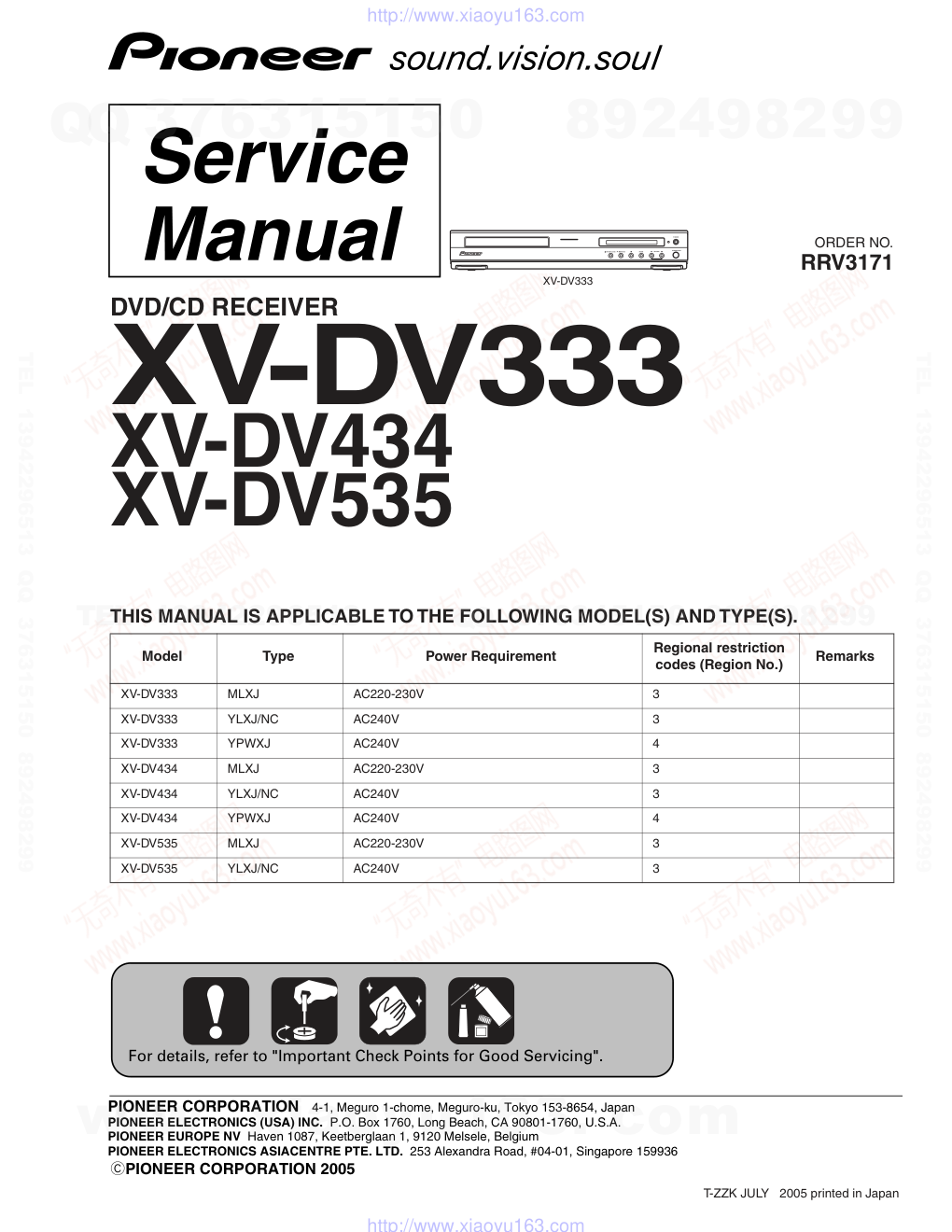
RRV3171
DVD/CD RECEIVER
XV-DV333
XV-DV434
XV-DV535
THIS MANUAL IS APPLICABLE TO THE FOLLOWING MODEL(S) AND TYPE(S).
Model
Type
Power Requirement
Regional restriction
codes (Region No.)
Remarks
XV-DV333
MLXJ
AC220-230V
3
XV-DV333
YLXJ/NC
AC240V
3
XV-DV333
YPWXJ
AC240V
4
XV-DV434
MLXJ
AC220-230V
3
XV-DV434
YLXJ/NC
AC240V
3
XV-DV434
YPWXJ
AC240V
4
XV-DV535
MLXJ
AC220-230V
3
XV-DV535
YLXJ/NC
AC240V
3
For details, refer to "Important Check Points for Good Servicing".
T-ZZK JULY 2005 printed in Japan
www. xiaoyu163. com
QQ 376315150
9
9
2
8
9
4
2
9
8
TEL 13942296513
9
9
2
8
9
4
2
9
8
0
5
1
5
1
3
6
7
3
Q
Q
TEL 13942296513 QQ 376315150 892498299
TEL 13942296513 QQ 376315150 892498299
http://www.xiaoyu163.com
XV-DV333
2
1
2
3
4
1
2
3
4
C
D
F
A
B
E
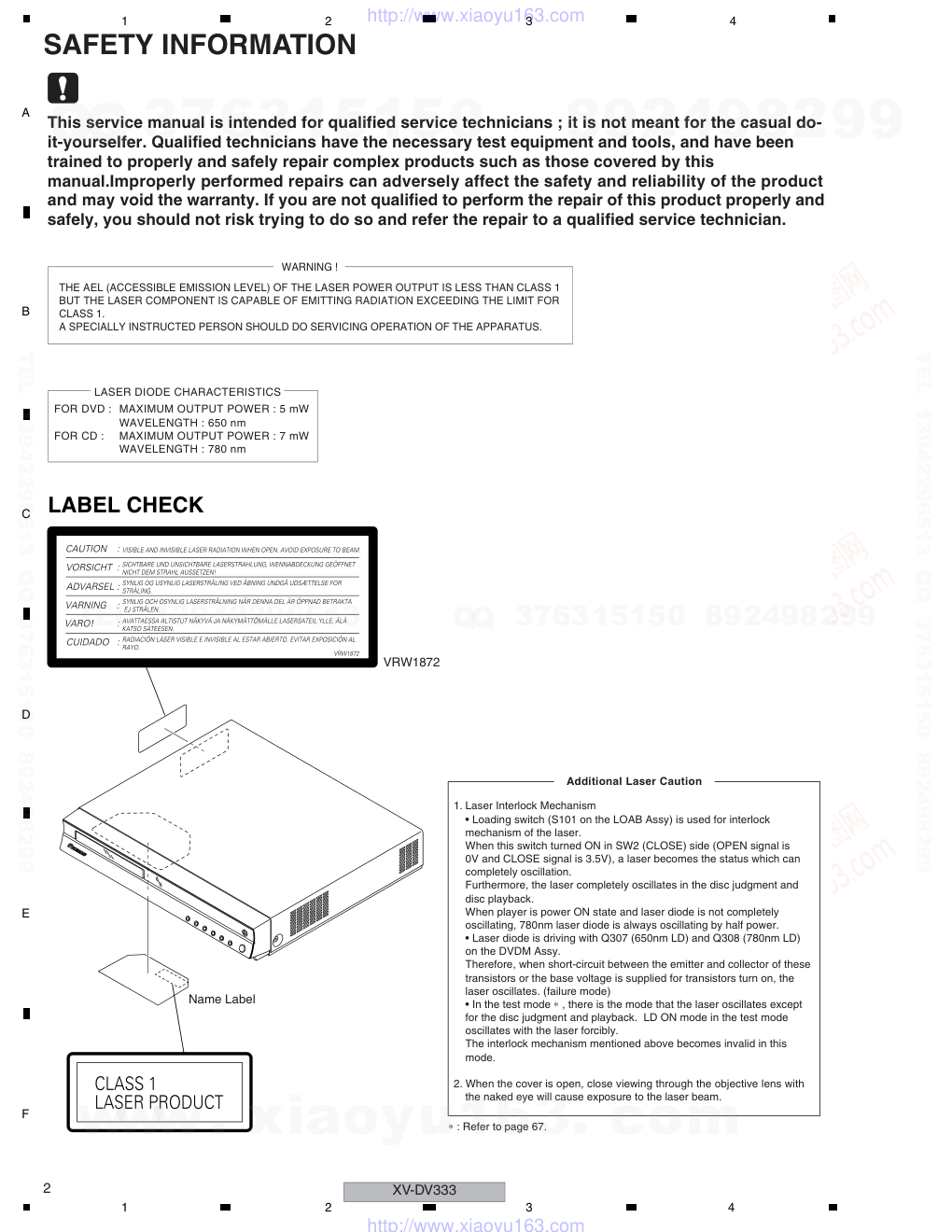
SAFETY INFORMATION
This service manual is intended for qualified service technicians ; it is not meant for the casual do-
it-yourselfer. Qualified technicians have the necessary test equipment and tools, and have been
trained to properly and safely repair complex products such as those covered by this
manual.Improperly performed repairs can adversely affect the safety and reliability of the product
and may void the warranty. If you are not qualified to perform the repair of this product properly and
safely, you should not risk trying to do so and refer the repair to a qualified service technician.
WARNING !
THE AEL (ACCESSIBLE EMISSION LEVEL) OF THE LASER POWER OUTPUT IS LESS THAN CLASS 1
BUT THE LASER COMPONENT IS CAPABLE OF EMITTING RADIATION EXCEEDING THE LIMIT FOR
CLASS 1.
A SPECIALLY INSTRUCTED PERSON SHOULD DO SERVICING OPERATION OF THE APPARATUS.
LASER DIODE CHARACTERISTICS
FOR DVD : MAXIMUM OUTPUT POWER : 5 mW
WAVELENGTH : 650 nm
FOR CD :
MAXIMUM OUTPUT POWER : 7 mW
WAVELENGTH : 780 nm
Additional Laser Caution
1. Laser Interlock Mechanism
• Loading switch (S101 on the LOAB Assy) is used for interlock
mechanism of the laser.
When this switch turned ON in SW2 (CLOSE) side (OPEN signal is
0V and CLOSE signal is 3.5V), a laser becomes the status which can
completely oscillation.
Furthermore, the laser completely oscillates in the disc judgment and
disc playback.
When player is power ON state and laser diode is not completely
oscillating, 780nm laser diode is always oscillating by half power.
• Laser diode is driving with Q307 (650nm LD) and Q308 (780nm LD)
on the DVDM Assy.
Therefore, when short-circuit between the emitter and collector of these
transistors or the base voltage is supplied for transistors turn on, the
laser oscillates. (failure mode)
• In the test mode ∗ , there is the mode that the laser oscillates except
for the disc judgment and playback. LD ON mode in the test mode
oscillates with the laser forcibly.
The interlock mechanism mentioned above becomes invalid in this
mode.
2. When the cover is open, close viewing through the objective lens with
the naked eye will cause exposure to the laser beam.
LABEL CHECK
VRW1872
Name Label
∗ : Refer to page 67.
www. xiaoyu163. com
QQ 376315150
9
9
2
8
9
4
2
9
8
TEL 13942296513
9
9
2
8
9
4
2
9
8
0
5
1
5
1
3
6
7
3
Q
Q
TEL 13942296513 QQ 376315150 892498299
TEL 13942296513 QQ 376315150 892498299
http://www.xiaoyu163.com
XV-DV333
3
5
6
7
8
5
6
7
8
C
D
F
A
B
E
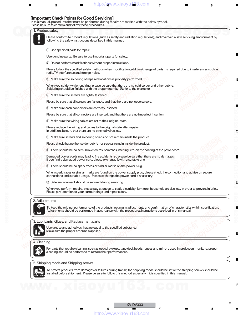
[Important Check Points for Good Servicing]
In this manual, procedures that must be performed during repairs are marked with the below symbol.
Please be sure to confirm and follow these procedures.
1. Product safety
Please conform to product regulations (such as safety and radiation regulations), and maintain a safe servicing environment by
following the safety instructions described in this manual.
1 Use specified parts for repair.
Use genuine parts. Be sure to use important parts for safety.
2 Do not perform modifications without proper instructions.
Please follow the specified safety methods when modification(addition/change of parts) is required due to interferences such as
radio/TV interference and foreign noise.
3 Make sure the soldering of repaired locations is properly performed.
When you solder while repairing, please be sure that there are no cold solder and other debris.
Soldering should be finished with the proper quantity. (Refer to the example)
4 Make sure the screws are tightly fastened.
Please be sure that all screws are fastened, and that there are no loose screws.
5 Make sure each connectors are correctly inserted.
Please be sure that all connectors are inserted, and that there are no imperfect insertion.
6 Make sure the wiring cables are set to their original state.
Please replace the wiring and cables to the original state after repairs.
In addition, be sure that there are no pinched wires, etc.
7 Make sure screws and soldering scraps do not remain inside the product.
Please check that neither solder debris nor screws remain inside the product.
8 There should be no semi-broken wires, scratches, melting, etc. on the coating of the power cord.
Damaged power cords may lead to fire accidents, so please be sure that there are no damages.
If you find a damaged power cord, please exchange it with a suitable one.
9 There should be no spark traces or similar marks on the power plug.
When spark traces or similar marks are found on the power supply plug, please check the connection and advise on secure
connections and suitable usage. Please exchange the power cord if necessary.
0 Safe environment should be secured during servicing.
When you perform repairs, please pay attention to static electricity, furniture, household articles, etc. in order to prevent injuries.
Please pay attention to your surroundings and repair safely.
2. Adjustments
To keep the original performance of the products, optimum adjustments and confirmation of characteristics within specification.
Adjustments should be performed in accordance with the procedures/instructions described in this manual.
4. Cleaning
For parts that require cleaning, such as optical pickups, tape deck heads, lenses and mirrors used in projection monitors, proper
cleaning should be performed to restore their performances.
3. Lubricants, Glues, and Replacement parts
Use grease and adhesives that are equal to the specified substance.
Make sure the proper amount is applied.
5. Shipping mode and Shipping screws
To protect products from damages or failures during transit, the shipping mode should be set or the shipping screws should be
installed before shipment. Please be sure to follow this method especially if it is specified in this manual.
www. xiaoyu163. com
QQ 376315150
9
9
2
8
9
4
2
9
8
TEL 13942296513
9
9
2
8
9
4
2
9
8
0
5
1
5
1
3
6
7
3
Q
Q
TEL 13942296513 QQ 376315150 892498299
TEL 13942296513 QQ 376315150 892498299
http://www.xiaoyu163.com
XV-DV333
4
1
2
3
4
1
2
3
4
C
D
F
A
B
E
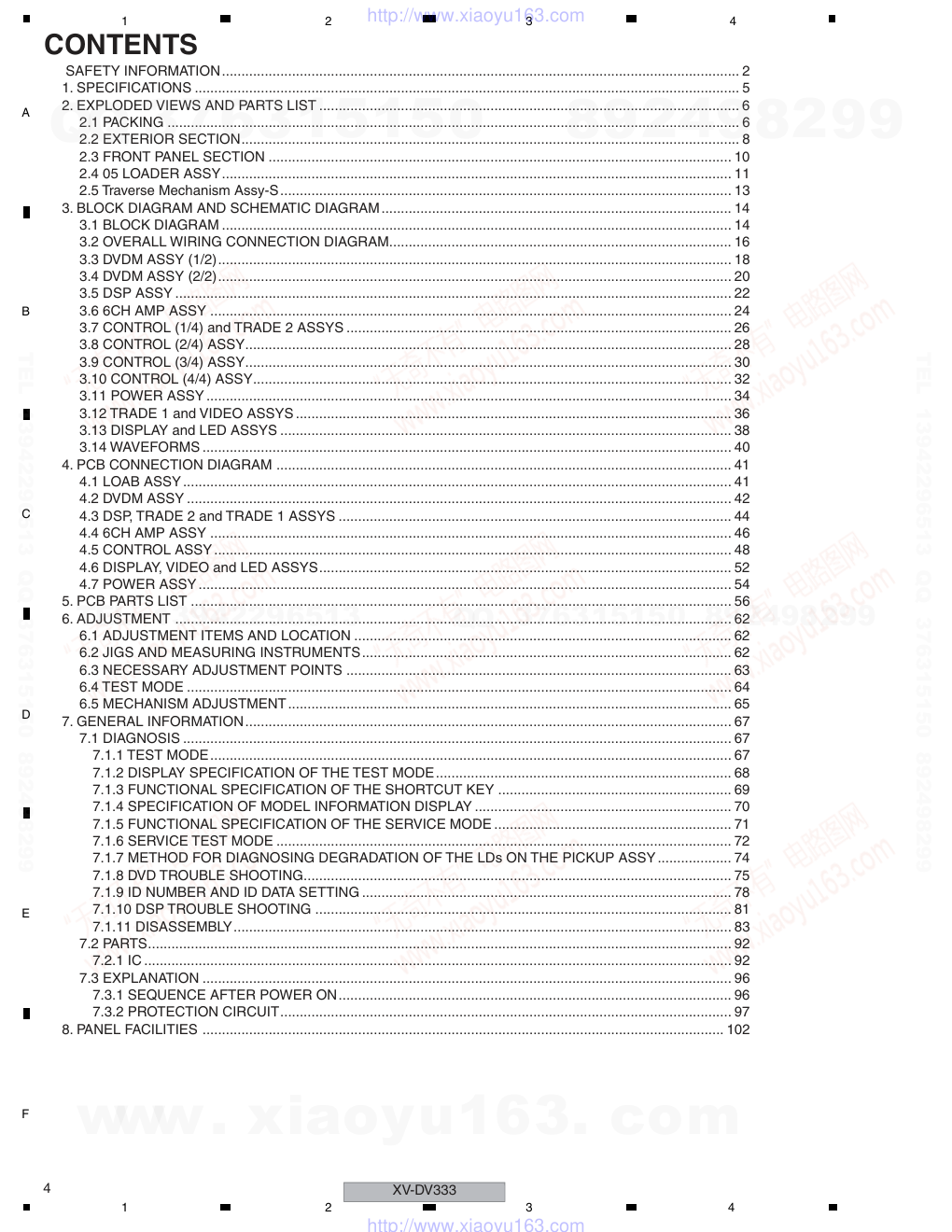
CONTENTS
SAFETY INFORMATION..................................................................................................................................... 2
1. SPECIFICATIONS ............................................................................................................................................ 5
2. EXPLODED VIEWS AND PARTS LIST ............................................................................................................ 6
2.1 PACKING ................................................................................................................................................... 6
2.2 EXTERIOR SECTION................................................................................................................................ 8
2.3 FRONT PANEL SECTION ....................................................................................................................... 10
2.4 05 LOADER ASSY................................................................................................................................... 11
2.5 Traverse Mechanism Assy-S.................................................................................................................... 13
3. BLOCK DIAGRAM AND SCHEMATIC DIAGRAM.......................................................................................... 14
3.1 BLOCK DIAGRAM ................................................................................................................................... 14
3.2 OVERALL WIRING CONNECTION DIAGRAM........................................................................................ 16
3.3 DVDM ASSY (1/2).................................................................................................................................... 18
3.4 DVDM ASSY (2/2).................................................................................................................................... 20
3.5 DSP ASSY ............................................................................................................................................... 22
3.6 6CH AMP ASSY ...................................................................................................................................... 24
3.7 CONTROL (1/4) and TRADE 2 ASSYS ................................................................................................... 26
3.8 CONTROL (2/4) ASSY............................................................................................................................. 28
3.9 CONTROL (3/4) ASSY............................................................................................................................. 30
3.10 CONTROL (4/4) ASSY........................................................................................................................... 32
3.11 POWER ASSY....................................................................................................................................... 34
3.12 TRADE 1 and VIDEO ASSYS ................................................................................................................ 36
3.13 DISPLAY and LED ASSYS .................................................................................................................... 38
3.14 WAVEFORMS ........................................................................................................................................ 40
4. PCB CONNECTION DIAGRAM ..................................................................................................................... 41
4.1 LOAB ASSY............................................................................................................................................. 41
4.2 DVDM ASSY ............................................................................................................................................ 42
4.3 DSP, TRADE 2 and TRADE 1 ASSYS ..................................................................................................... 44
4.4 6CH AMP ASSY ...................................................................................................................................... 46
4.5 CONTROL ASSY..................................................................................................................................... 48
4.6 DISPLAY, VIDEO and LED ASSYS.......................................................................................................... 52
4.7 POWER ASSY......................................................................................................................................... 54
5. PCB PARTS LIST ........................................................................................................................................... 56
6. ADJUSTMENT ............................................................................................................................................... 62
6.1 ADJUSTMENT ITEMS AND LOCATION ................................................................................................. 62
6.2 JIGS AND MEASURING INSTRUMENTS............................................................................................... 62
6.3 NECESSARY ADJUSTMENT POINTS ................................................................................................... 63
6.4 TEST MODE ............................................................................................................................................ 64
6.5 MECHANISM ADJUSTMENT.................................................................................................................. 65
7. GENERAL INFORMATION............................................................................................................................. 67
7.1 DIAGNOSIS ............................................................................................................................................. 67
7.1.1 TEST MODE...................................................................................................................................... 67
7.1.2 DISPLAY SPECIFICATION OF THE TEST MODE............................................................................ 68
7.1.3 FUNCTIONAL SPECIFICATION OF THE SHORTCUT KEY ............................................................ 69
7.1.4 SPECIFICATION OF MODEL INFORMATION DISPLAY .................................................................. 70
7.1.5 FUNCTIONAL SPECIFICATION OF THE SERVICE MODE ............................................................. 71
7.1.6 SERVICE TEST MODE ..................................................................................................................... 72
7.1.7 METHOD FOR DIAGNOSING DEGRADATION OF THE LDs ON THE PICKUP ASSY................... 74
7.1.8 DVD TROUBLE SHOOTING.............................................................................................................. 75
7.1.9 ID NUMBER AND ID DATA SETTING ............................................................................................... 78
7.1.10 DSP TROUBLE SHOOTING ........................................................................................................... 81
7.1.11 DISASSEMBLY................................................................................................................................ 83
7.2 PARTS...................................................................................................................................................... 92
7.2.1 IC ....................................................................................................................................................... 92
7.3 EXPLANATION ........................................................................................................................................ 96
7.3.1 SEQUENCE AFTER POWER ON..................................................................................................... 96
7.3.2 PROTECTION CIRCUIT.................................................................................................................... 97
8. PANEL FACILITIES ...................................................................................................................................... 102
www. xiaoyu163. com
QQ 376315150
9
9
2
8
9
4
2
9
8
TEL 13942296513
9
9
2
8
9
4
2
9
8
0
5
1
5
1
3
6
7
3
Q
Q
TEL 13942296513 QQ 376315150 892498299
TEL 13942296513 QQ 376315150 892498299
http://www.xiaoyu163.com
XV-DV333
5
5
6
7
8
5
6
7
8
C
D
F
A
B
E
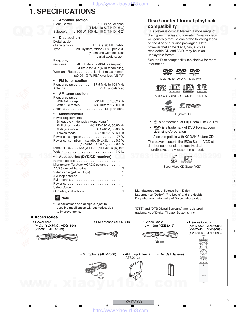
1. SPECIFICATIONS
Accessories
• Power cord
(MLXJ, YLXJ/NC : ADG1154)
(YPWXJ : ADG7099)
• FM Antenna (ADH7030)
• Microphone (APM7006)
• AM Loop Antenna
(ATB7013)
• Video Cable
(L = 1.5m) (XDE3046)
• Remote Control
(XV-DV333 : XXD3093)
(XV-DV434 : XXD3093)
(XV-DV535 : XXD3095)
• Dry Cell Batteries
Yellow
ST+
TUNE+
ENTER
TUNE-
MASTER
VOLUME
ST-
STANDBY/ON
CD
FM/AM
OPEN CLOSE
DVD
TUNER
TV
LINE
L1/L2
1
4
4
¡
8
3
7
0
DVD MENU
RETURN
BASS
MODE
TV CONTROL
CH
VOL
INPUT
OPEN
MUTE
FRONT
SURROUND
Note
• Specifications and design subject to
possible modification without notice, due
to improvements.
Manufactured under license from Dolby
Laboratories.“Dolby”, “Pro Logic” and the double-
D symbol are trademarks of Dolby Laboratories.
“DTS” and “DTS Digital Surround” are registered
trademarks of Digital Theater Systems, Inc.
Disc / content format playback
compatibility
This player is compatible with a wide range of
disc types (media) and formats. Playable discs
will generally feature one of the following logos
on the disc and/or disc packaging. Note
however that some disc types, such as
recordable CD and DVD, may be in an
unplayable format.
See the Disc compatibility tablebelow for more
information.
•
is a trademark of Fuji Photo Film Co. Ltd.
•
is a trademark of DVD Format/Logo
Licensing Corporation
Also compatible with KODAK Picture CD
This player supports the IECís Su per VCD stan-
dard for superior picture quality, dual
soundtracks, and widescreen support.
DVD-Video DVD-R
DVD-RW
Video CD
Fujicolor CD
Audio CD
CD-R
CD-RW
VIDEO
CD
Super Video CD (Super VCD)
•
Amplifier section
•
Disc section
Front, Center. . . . . . . . . . . . . . .100 W per channel
(1 kHz, 10 % T.H.D., 6 Ω)
Subwoofer. . . . 100 W (100 Hz, 10 % T.H.D., 6 Ω)
Digital audio
characteristics . . . . . . . . . . DVD fs: 96 kHz, 24-bit
Type . . . . . . . . DVD system, Video CD/Super VCD
system and Compact Disc
digital audio system
Frequency
response . . . . . . 4Hz to 44 kHz (96kHz sampling) /
4 Hz to 22 kHz (48kHz sampling)
Wow and Flutter
Limit of measurement
(±0.001 % W.PEAK) or less (JEITA)
•
FM tuner section
Frequency range. . . . . . . . . 87.5 MHz to 108 MHz
Antenna . . . . . . . . . . . . . . . . . . . 75 Ω, unbalanced
•
AM tuner section
Frequency range
With 9kHz step . . . . . . . . . 531 kHz to 1,602 kHz
With 10kHz step . . . . . . . . 530 kHz to 1,700 kHz
Antenna . . . . . . . . . . . . . . . . . . . . . . Loop antenna
•
Miscellaneous
Power requirements:
Singapore / Indonesia / Hong Kong /
Phillipines model . . . . . AC 220-230 V, 50/60 Hz
Malaysia model. . . . . . . . . . AC 240 V, 50/60 Hz
Taiwan model. . . . . . . . . . AC 110-120 V, 60 Hz
Power consumption . . . . . . . . . . . . . . . . . . . 175 W
Power consumption in standby (MLXJ). . . . . 0.5 W
(YLXJ/NC, YPWXJ). . . . . 0.6 W
Dimensions. . . . . 420 (W) x 70 (H) x 399.5 (D) mm
Weight . . . . . . . . . . . . . . . . . . . . . . . . . . . . . 7.0 kg
•
Accessories (DVD/CD receiver)
Remote control . . . . . . . . . . . . . . . . . . . . . . . . . . 1
Microphone (for Auto MCACC setup). . . . . . . . . 1
AA/R6 dry cell batteries . . . . . . . . . . . . . . . . . . . 2
Video cable (yellow plugs) . . . . . . . . . . . . . . . . . . 1
AM loop antenna . . . . . . . . . . . . . . . . . . . . . . . . . 1
FM antenna . . . . . . . . . . . . . . . . . . . . . . . . . . . . . 1
Power cord . . . . . . . . . . . . . . . . . . . . . . . . . . . . . 1
Setup Guide . . . . . . . . . . . . . . . . . . . . . . . . . . . . 1
Operating instructions . . . . . . . . . . . . . . . . . . . . 1
. . . . . . . . .
www. xiaoyu163. com
QQ 376315150
9
9
2
8
9
4
2
9
8
TEL 13942296513
9
9
2
8
9
4
2
9
8
0
5
1
5
1
3
6
7
3
Q
Q
TEL 13942296513 QQ 376315150 892498299
TEL 13942296513 QQ 376315150 892498299
http://www.xiaoyu163.com
XV-DV333
6
1
2
3
4
1
2
3
4
C
D
F
A
B
E
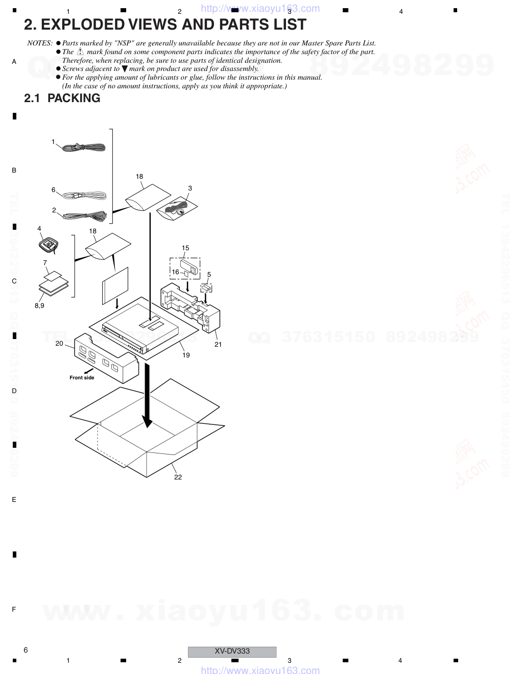
2. EXPLODED VIEWS AND PARTS LIST
2.1 PACKING
Parts marked by "NSP" are generally unavailable because they are not in our Master Spare Parts List.
The mark found on some component parts indicates the importance of the safety factor of the part.
Therefore, when replacing, be sure to use parts of identical designation.
Screws adjacent to mark on product are used for disassembly.
For the applying amount of lubricants or glue, follow the instructions in this manual.
(In the case of no amount instructions, apply as you think it appropriate.)
NOTES:
Front side
15
5
21
19
20
16
18
18
3
4
7
8,9
1
6
2
22
www. xiaoyu163. com
QQ 376315150
9
9
2
8
9
4
2
9
8
TEL 13942296513
9
9
2
8
9
4
2
9
8
0
5
1
5
1
3
6
7
3
Q
Q
TEL 13942296513 QQ 376315150 892498299
TEL 13942296513 QQ 376315150 892498299
http://www.xiaoyu163.com
XV-DV333
7
5
6
7
8
5
6
7
8
C
D
F
A
B
E
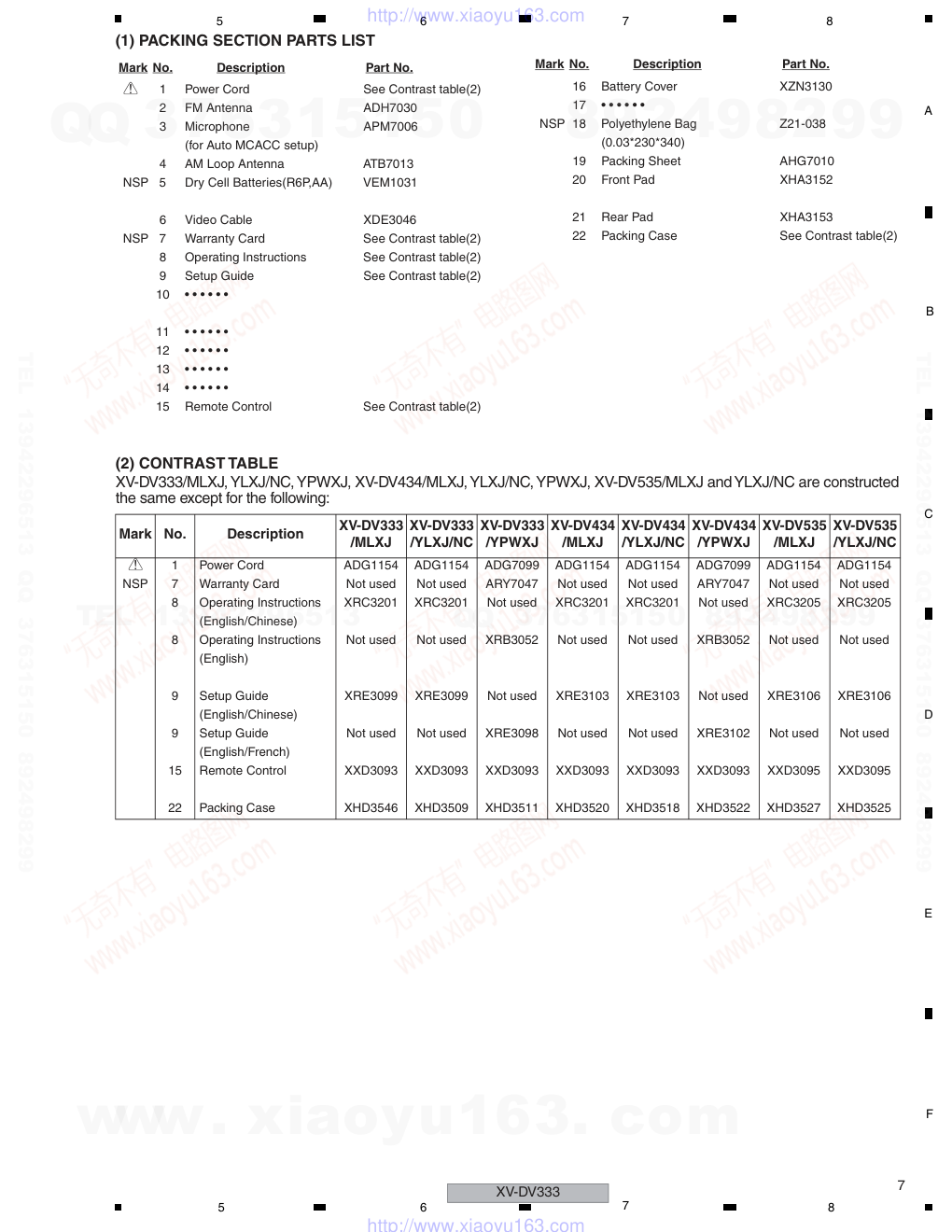
(1) PACKING SECTION PARTS LIST
(2) CONTRAST TABLE
XV-DV333/MLXJ, YLXJ/NC, YPWXJ, XV-DV434/MLXJ, YLXJ/NC, YPWXJ, XV-DV535/MLXJ and YLXJ/NC are constructed
the same except for the following:
Mark No.
Description
Part No.
>
1
Power Cord
See Contrast table(2)
2
FM Antenna
ADH7030
3
Microphone
APM7006
(for Auto MCACC setup)
4
AM Loop Antenna
ATB7013
NSP
5
Dry Cell Batteries(R6P,AA)
VEM1031
6
Video Cable
XDE3046
NSP
7
Warranty Card
See Contrast table(2)
8
Operating Instructions
See Contrast table(2)
9
Setup Guide
See Contrast table(2)
10
• • • • • •
11
• • • • • •
12
• • • • • •
13
• • • • • •
14
• • • • • •
15
Remote Control
See Contrast table(2)
16
Battery Cover
XZN3130
17
• • • • • •
NSP 18
Polyethylene Bag
Z21-038
(0.03*230*340)
19
Packing Sheet
AHG7010
20
Front Pad
XHA3152
21
Rear Pad
XHA3153
22
Packing Case
See Contrast table(2)
Mark No.
Description
Part No.
Mark
No.
Description
XV-DV333
/MLXJ
XV-DV333
/YLXJ/NC
XV-DV333
/YPWXJ
XV-DV434
/MLXJ
XV-DV434
/YLXJ/NC
XV-DV434
/YPWXJ
XV-DV535
/MLXJ
XV-DV535
/YLXJ/NC
>
1
Power Cord
ADG1154
ADG1154
ADG7099
ADG1154
ADG1154
ADG7099
ADG1154
ADG1154
NSP
7
Warranty Card
Not used
Not used
ARY7047
Not used
Not used
ARY7047
Not used
Not used
8
Operating Instructions
XRC3201
XRC3201
Not used
XRC3201
XRC3201
Not used
XRC3205
XRC3205
(English/Chinese)
8
Operating Instructions
Not used
Not used
XRB3052
Not used
Not used
XRB3052
Not used
Not used
(English)
9
Setup Guide
XRE3099
XRE3099
Not used
XRE3103
XRE3103
Not used
XRE3106
XRE3106
(English/Chinese)
9
Setup Guide
Not used
Not used
XRE3098
Not used
Not used
XRE3102
Not used
Not used
(English/French)
15
Remote Control
XXD3093
XXD3093
XXD3093
XXD3093
XXD3093
XXD3093
XXD3095
XXD3095
22
Packing Case
XHD3546
XHD3509
XHD3511
XHD3520
XHD3518
XHD3522
XHD3527
XHD3525
www. xiaoyu163. com
QQ 376315150
9
9
2
8
9
4
2
9
8
TEL 13942296513
9
9
2
8
9
4
2
9
8
0
5
1
5
1
3
6
7
3
Q
Q
TEL 13942296513 QQ 376315150 892498299
TEL 13942296513 QQ 376315150 892498299
http://www.xiaoyu163.com
XV-DV333
8
1
2
3
4
1
2
3
4
C
D
F
A
B
E
2.2 EXTERIOR SECTION
E
A
F
D
B
C
J
K
H
E
F
J
D
C
B
K
H
A
I
I
G
G
I
C
F
E
G
D
J
B
CONTACT SIDE
NON-CONTACT
SIDE
17
48
48
48
48
46
46 47
46
46
46
46
46
21
22
5
8
23
51
52
52
52
13
24
49
49
49
49
46
46
46
34
35
35
16
33
36
37
54
43
54
46
42
41
40
39
12
53
53
38
49
15
49
27
28
29
30
50
31
32
32
50
50
3
50
55
25
26
26
26
52
52x4
52
4
10
11
6
7
56
47
9
14
18
46
1
2
48
19
20
57
MLXJ only
Except
YPWXJ
YPWXJ only
Refer to
"2.3 FRONT PANEL SECTION."
Refer to
"2.4 05 LOADER ASSY."
45
58
Cleaning paper
GED-008
www. xiaoyu163. com
QQ 376315150
9
9
2
8
9
4
2
9
8
TEL 13942296513
9
9
2
8
9
4
2
9
8
0
5
1
5
1
3
6
7
3
Q
Q
TEL 13942296513 QQ 376315150 892498299
TEL 13942296513 QQ 376315150 892498299
http://www.xiaoyu163.com
XV-DV333
9
5
6
7
8
5
6
7
8
C
D
F
A
B
E
(1) EXTERIOR SECTION PARTS LIST
(2) CONTRAST TABLE
XV-DV333/MLXJ, YLXJ/NC, YPWXJ, XV-DV434/MLXJ, YLXJ/NC, YPWXJ, XV-DV535/MLXJ and YLXJ/NC are constructed
the same except for the following:
Mark No.
Description
Part No.
1
CONTROL Assy
See Contrast table(2)
2
DSP Assy
AWX8587
3
DVDM Assy
AWM7962
4
POWER Assy
XWZ3975
5
TRADE1 Assy
XWZ3997
6
TRADE2 Assy
XWZ3998
7
VIDEO Assy
XWZ3980
8
6 CH AMP
XWK3188
9
FM/AM TUNER Unit
AXX7173
>
10
Fuse (FU1: T2.5A)
REK1026
>
11
Fuse (FU2: T5.0A)
REK1029
>
12
Power Transformer (T1)
See Contrast table(2)
13
DC Fan Motor
XXM3009
14
11P F.F.C/60V
XDD3152
15
27P F.F.C/60V
XDD3188
16
25P F.F.C/60V
XDD3157
17
Bonnet Case
XZN3160
NSP 18
PCB Spacer(3X6)
AEC7156
19
Push Rivet
See Contrast table(2)
20
Fan Barrier
See Contrast table(2)
21
Fan Cover
XMR3086
22
Rear Panel
See Contrast table(2)
NSP 23
AMP Unit 6ch
XXQ3004
24
Fan Plate
ANG7462
NSP 25
Heat Sink
XNH3038
26
FET Bracket A
ANG7418
NSP 27
DVD Assy
AXA7145
NSP 28
05 LOADER Assy
VWT1219
29
Adaptor 05L
ANW7282
30
Adaptor 05R
ANW7283
31
Connector Assy
PG05KK-E07
32
Cushion
AEB7267
33
Barrier VK1
AEC7533
NSP 34
Spacer
PNY-404
35
Control Angle
XNG3108
36
PCB Spacer
AEB7206
37
Bottom Plate
XEC3058
38
Locking Card Spacer
AEC7372
NSP 39
Chassis
XNA3024
40
S Cover
AEB7262
41
Card Spacer
DNK2769
42
Name Label
XAX3454
43
Tray Cap Assy
See Contrast table(2)
44
• • • • • •
45
Caution Label
VRW1872
46
Screw
BBZ30P060FTC
47
Screw
VPZ30P100FTC
48
Screw
BBZ30P080FNI
49
Screw
VBZ30P080FTC
50
Screw
BPZ30P080FNI
51
Screw
BBZ30P300FTC
52
Screw
BBZ30P140FTC
53
Screw
BBZ40P060FTC
54
Screw
CBZ30P080FTC
55
Screw
VPZ30P140FTC
56
Screw
PPZ30P080FNI
NSP 57
SISIR Label
See Contrast table(2)
NSP 58
Energy Star Label
See Contrast table(2)
Mark No.
Description
Part No.
Mark
No.
Description
XV-DV333
/MLXJ
XV-DV333
/YLXJ/NC
XV-DV333
/YPWXJ
XV-DV434
/MLXJ
XV-DV434
/YLXJ/NC
XV-DV434
/YPWXJ
XV-DV535
/MLXJ
XV-DV535
/YLXJ/NC
1
CONTROL Assy
XWZ3969
XWZ3969
XWZ3969
XWZ3984
XWZ3984
XWZ3984
XWZ3989
XWZ3989
>
12
Power Transformer (T1)
XTS3077
XTS3078
XTS3078
XTS3077
XTS3078
XTS3078
XTS3077
XTS3078
19
Push Rivet
XEC3034
XEC3034
Not used
XEC3034
XEC3034
Not used
XEC3034
XEC3034
20
Fan Barrier
XMR3089
XMR3089
Not used
XMR3089
XMR3089
Not used
XMR3089
XMR3089
22
Rear Panel
XNC3351
XNC3357
XNC3340
XNC3367
XNC3368
XNC3372
XNC3354
XNC3353
43
Tray Cap Assy
XXG3207
XXG3207
XXG3207
XXG3207
XXG3207
XXG3207
XXG3211
XXG3211
NSP
57
SISIR Label
XAX3513
Not used
Not used
XAX3514
Not used
Not used
XAX3515
Not used
NSP
58
Energy Star Label
Not used
Not used
AAX8022
Not used
Not used
AAX8022
Not used
Not used
www. xiaoyu163. com
QQ 376315150
9
9
2
8
9
4
2
9
8
TEL 13942296513
9
9
2
8
9
4
2
9
8
0
5
1
5
1
3
6
7
3
Q
Q
TEL 13942296513 QQ 376315150 892498299
TEL 13942296513 QQ 376315150 892498299
http://www.xiaoyu163.com
XV-DV333
10
1
2
3
4
1
2
3
4
C
D
F
A
B
E
2.3 FRONT PANEL SECTION
(1) FRONT PANEL SECTION PARTS LIST
(2) CONTRAST TABLE
XV-DV333/MLXJ, YLXJ/NC, YPWXJ, XV-DV434/MLXJ, YLXJ/NC, YPWXJ, XV-DV535/MLXJ and YLXJ/NC are constructed
the same except for the following:
H
K
CONTACT SIDE
NON-CONTACT
SIDE
4
7
5
6
8
9
10
11
3
2
1
12
12
12
Mark No.
Description
Part No.
1
DISPLAY Assy
XWZ3979
2
LED Assy
XWZ4000
3
19P F.F.C/60V
XDD3158
NSP
4
Front Panel Assy
See Contrast table(2)
5
Front Panel
See Contrast table(2)
6
Pioneer Name Plate
VAM1129
7
Illumination Lens
AAK8214
8
Display Window
See Contrast table(2)
9
Leg
AEB7090
10
FUNC. Button
XAD3209
11
Screw
BPZ30P080FTC
12
Screw
VPZ30P100FTC
Mark No.
Description
Part No.
Mark
No.
Description
XV-DV333
/MLXJ
XV-DV333
/YLXJ/NC
XV-DV333
/YPWXJ
XV-DV434
/MLXJ
XV-DV434
/YLXJ/NC
XV-DV434
/YPWXJ
XV-DV535
/MLXJ
XV-DV535
/YLXJ/NC
NSP
4
Front Panel Assy
XXG3225
XXG3225
XXG3225
XXG3227
XXG3227
XXG3227
XXG3229
XXG3229
5
Front Panel
XMB3207
XMB3207
XMB3207
XMB3208
XMB3208
XMB3208
XMB3209
XMB3209
8
Display Window
XAK3485
XAK3485
XAK3485
XAK3485
XAK3485
XAK3485
XAK3487
XAK3487
www. xiaoyu163. com
QQ 376315150
9
9
2
8
9
4
2
9
8
TEL 13942296513
9
9
2
8
9
4
2
9
8
0
5
1
5
1
3
6
7
3
Q
Q
TEL 13942296513 QQ 376315150 892498299
TEL 13942296513 QQ 376315150 892498299
http://www.xiaoyu163.com
XV-DV333
11
5
6
7
8
5
6
7
8
C
D
F
A
B
E
2.4 05 LOADER ASSY
05 LOADER ASSY PARTS LIST
A
A
To DVDM CN101 (Pickup)
To DVDM CN104 (Stepping Motor)
To DVDM CN102 (Spindle Motor)
To
DVDM CN103
2
Refer to
"2.5 Traverse Mechanism Assy-S".
12
23
13
17
21
16
22
15
14
22
22
22
20
19
9
1
7
10
11
6
8
8
8
8
18
24
A
Lubricating Oil
GYA1001
Daifree
GEM1036
Refer to
" Application of Lubricant".
Note :
Lubricating Oil
GYA1001
3
Pickup leneses
Cleaning liquid
GEM1004
Cleaning paper
GED-008
Mark No.
Description
Part No.
NSP
1
LOAB Assy
VWG2346
2
Traverse Mechanism Assy-S
DXX2568
3
Loading Motor Assy
VXX2912
4
• • • • •
5
• • • • •
6
Flexible Cable (24P)
VDA2008
7
Connector Assy 2P
VKP2253
8
Floating Rubber
VEB1351
9
Belt
VEB1358
10
Stabilizer
VNE2253
11
Loading Base
VNL1917
12
Float Base 04
VNL1968
13
Drive Cam
VNL1919
14
Gear Pulley
VNL1921
15
Loading Gear
VNL1922
16
Drive Gear
VNL1923
17
SW Lever
VNL1925
18
Clamper Plate 04
VNE2342
19
Bridge 04
VNE2343
20
Clamper 04
VNL1969
21
Screw
JGZ17P028FTC
22
Screw
VBA1094
23
Tray
VNL1920
24
Clamp Magnet
VMG1029
Mark No.
Description
Part No.
www. xiaoyu163. com
QQ 376315150
9
9
2
8
9
4
2
9
8
TEL 13942296513
9
9
2
8
9
4
2
9
8
0
5
1
5
1
3
6
7
3
Q
Q
TEL 13942296513 QQ 376315150 892498299
TEL 13942296513 QQ 376315150 892498299
http://www.xiaoyu163.com
XV-DV333
12
1
2
3
4
1
2
3
4
C
D
F
A
B
E
Application of Lubricant
Lubricating Oil
GYA1001
Around the shaft
No. 11
Loading Base
No. 13
Drive Cam
No. 13
Drive Cam
No. 23
Tray
No. 23
Tray
Front View
Rear View
Daifree
GEM1036
Inner side of a ditch
Concave of unevenness
Top View
Bottom View
Daifree
GEM1036
Daifree
GEM1036
Side of the rib
Concave of unevenness
Daifree
GEM1036
Concave of unevenness
Daifree
GEM1036
Inner side of a ditch
Lubricating Oil
GYA1001
Inner side of a ditch
Lubricating Oil
GYA1001
Lubricating Oil
GYA1001
Lubricating Oil
GYA1001
Lubricating Oil
GYA1001
Lubricating Oil
GYA1001
www. xiaoyu163. com
QQ 376315150
9
9
2
8
9
4
2
9
8
TEL 13942296513
9
9
2
8
9
4
2
9
8
0
5
1
5
1
3
6
7
3
Q
Q
TEL 13942296513 QQ 376315150 892498299
TEL 13942296513 QQ 376315150 892498299
http://www.xiaoyu163.com
XV-DV333
13
5
6
7
8
5
6
7
8
C
D
F
A
B
E
2.5 Traverse Mechanism Assy-S
Traverse Mechanism Assy-S PARTS LIST
To
DVDM CN101
(Pickup Assy)
To
DVDM CN104
(Stepping Motor)
To DVDM CN102
(Spindle Motor)
CONTACT SIDE
NON-CONTACT
SIDE
13
10
10
11
11
12
2
4
1
3
6
9
5
7
Silicone Adhesive
GEM1037
Refer to
" Application of Lubricant".
Note :
Note : When part #2 is replaced,
part #13 also need to be
replaced at the same time.
8
Note : Spindle screw (DBA1252) of No.13 is the screw which applied special bond.
Therefore the adhesion becomes ineffective when takes it off once. Spindle screw is the part which cannot recycle.
When part #2 is replaced, part #13 also need to be replaced at the same time.
Mark No.
Description
Part No.
>
1
05SD Pickup Assy-S
OXX8014
2
Spindle Motor N200
DXM1197
3
Guide Shaft VK1
DLA1940
4
Sub Guide Shaft VK1
DLA1941
NSP
5
Joint VK1B
DNK4272
6
Joint Spring VK1
DBK1235
7
Stepping Motor VK1
DXM1201
NSP
8
Mechanism Frame VK1
DNK4160
9
Precision Screw VK1
DBA1209
10
Skew Screw VK1
DBA1211
11
Skew Spring VK1
DBH1516
NSP 12
Stepping Screw
DBA1205
13
Spindle Screw VK1(for Service) DBA1252
Mark No.
Description
Part No.
www. xiaoyu163. com
QQ 376315150
9
9
2
8
9
4
2
9
8
TEL 13942296513
9
9
2
8
9
4
2
9
8
0
5
1
5
1
3
6
7
3
Q
Q
TEL 13942296513 QQ 376315150 892498299
TEL 13942296513 QQ 376315150 892498299
http://www.xiaoyu163.com
XV-DV333
14
1
2
3
4
1
2
3
4
C
D
F
A
B
E
3. BLOCK DIAGRAM AND SCHEMATIC DIAGRAM
3.1 BLOCK DIAGRAM
CN3101
DOUT
V
SY
SC
CY/G
Cb/B
Cr/R
VDET
VPR+8
VPR+8M
VDVD+12
VDET
VPR+8
VPR+8M
VDVD+12
- 6dB
- 10dB
IC3001
INPUT
SELECTOR
LINE 1
IN
TV IN
LINE 2 IN
(OPT DIGITAL)
BUFFER
IC3003
ATTENUATOR
IC701
AK4628VQE
8ch
CODEC
• Dolby Digital Decoder
• Dolby PrologicII
• DTS Decoder
IC801
DSPC56371AF180
IC601
AK4117VF
DIR
64M SDRAM
16M
FLASH ROM
SPINDLE
Motor
04SD PU
PlCK UP
ASSY
FTS &
SPDL DRlVER
BD7995EFS
Stepping
Motor
M
+ -
LOAB
Ass'y
27MHz
Loading
Motor
M
+ -
VlDEO AMP
DRlVER
MM1623BF
MT1389FE/C2-L-K
BACK END IC
• RF Amp
• Servo control
• Systemcontrol CPU
• AV decoder
• 108MHz 12bit Video DAC
POWER SUPPLY
1.8V
3.3V
5V
6.8V
12V
VK-1
16K
EEPROM
DVDM ASSY
B
DSP ASSY
C
FM/AM
TUNER
UNIT
CN5102
CN901
CN901
CN5102
CN5532
CN5522
CN5512
CN951
CN5620
1
2
LIVE
NEUTRAL
AC IN
IC201
IC101
IC204
IC203
IC202
IC401
CN903
CN901
CN5613
CN901
CN5613
CN5502
4
3
1
3
1
4
2
&
&
#
#
CN701
CN701
CN5612
CN5612
LIN
DIN
RIN
POWER ASSY (2/2)
J
TRADE2 ASSY (2/2)
E
4
4
www. xiaoyu163. com
QQ 376315150
9
9
2
8
9
4
2
9
8
TEL 13942296513
9
9
2
8
9
4
2
9
8
0
5
1
5
1
3
6
7
3
Q
Q
TEL 13942296513 QQ 376315150 892498299
TEL 13942296513 QQ 376315150 892498299
http://www.xiaoyu163.com
XV-DV333
15
5
6
7
8
5
6
7
8
C
D
F
A
B
E
CN8802
C
Y
S-VIDEO
OUT
SR PLUS
V
Cb
Cr
Y
COMPONENT&
COMPOSITE
VIDEO OUT
JA8851
ANDREW BYPASS
IC3301
STK433-270
• 3ch Power Amp
IC3401
STK433-270
• 3ch Power Amp
Headphone
AMP
HEADPHONE
FL/FR
OUT
SW
OUT
CENTRE
OUT
SL/SR
OUT
micro
Processoer
IC5601
FL
Driver IC
PT6302
ANDREW
FL Tube
IR
SENSOR
KEY
PDC122
IC5501
• 6ch E-vol
IC3062
E-VOL
BD3814FV
-
+
LPF
FL/FR
SW
Centre
SL/SR
REC OUT
DTS,LFE
MIX/GAIN
MICAMP
MCACC
+0dB
+0dB
+0dB
LED ASSY
K
1 2
J5602
1 2
J5601
VFL+5
LED
VFL+5
VIDEO ASSY
I
JA101
CN8801
DISPLAY ASSY
H
AMP UNIT 6CH
H
FAN
CONTROL ASSY
F
J
POWER SUPPLY ASSY (1/2)
TRADE2
ASSY
(1/2)
E
TRADE1 ASSY
G
CN3001
CN3011
CN3021
CN3031
CN3002
CN3012
CN3022
CN3032
CN5531
CN5521
CN5511
CN5501
IC3002
+6dB
IC9091
WIRELESS
OUT
WIRELESS OUT
SELECT
WIRE LESS MODEL ONLY
www. xiaoyu163. com
QQ 376315150
9
9
2
8
9
4
2
9
8
TEL 13942296513
9
9
2
8
9
4
2
9
8
0
5
1
5
1
3
6
7
3
Q
Q
TEL 13942296513 QQ 376315150 892498299
TEL 13942296513 QQ 376315150 892498299
http://www.xiaoyu163.com
XV-DV333
16
1
2
3
4
1
2
3
4
C
D
F
A
B
E
3.2 OVERALL WIRING CONNECTION DIAGRAM
JA8851
FAN
GND
4
1
3
2
Cb
YGND
1
2
Y
YGND
CbGND
Cr
6
5
LOAB ASSY
(VWG2346)
A
A
J
POWER ASSY(XWZ3975)
VIDEO ASSY
(XWZ3980)
I
B 1/2- B 2/2
B
DVDM ASSY (AWM7964)
DVD ASSY (AXA7145)
MLXJ : XTS3077
YLXJ/NC, YPWXJ : XTS3078
XKP3084
÷ When ordering service parts, be sure to refer to "EXPLODED VIEWS and PARTS LIST" or
"PCB PARTS LIST".
÷ The > mark found on some component parts indicates the importance of the safety factor
of the part. Therefore, when replacing, be sure to use parts of identical designation.
÷
: The power supply is shown with the marked box.
www. xiaoyu163. com
QQ 376315150
9
9
2
8
9
4
2
9
8
TEL 13942296513
9
9
2
8
9
4
2
9
8
0
5
1
5
1
3
6
7
3
Q
Q
TEL 13942296513 QQ 376315150 892498299
TEL 13942296513 QQ 376315150 892498299
http://www.xiaoyu163.com
XV-DV333
17
5
6
7
8
5
6
7
8
C
D
F
A
B
E
52044-1545
52045-1545
TORX179PL
XKP3071
XKP3082
XKP3082
XKP3071
XKP3082
XKP3082
XKP3071
XKP3071
XKP3071
XKP3071
52045-1145
XKP3082
XKP3082
KM200SA2
XKP3082
XKP3082
XKE3036
XKP3071
14
15
16
16
17
17
1
2
13
9
12
11
8
10
6
8
4
5
3
7
6
2
4
7
3
5
13
9
12
11
10
14
15
1
2
1
3
1
1
5
6
7
8
9
4
3
2
16
15
17
11
12
13
14
10
5
6
7
8
9
4
3
2
16
15
17
11
12
13
14
10
22
21
23
18
20
19
4
3
2
1
6
5
7
8
22
21
23
18
20
19
5
7
8
4
3
2
1
6
16
10
14
11
12
13
15
9
22
21
23
18
17
20
19
11
12
13
14
9
10
16
15
20
19
22
21
23
18
17
1
1
9
6
4
3
2
7
8
9
4
3
2
5
5
6
7
8
10
11
12
13
14
10
16
16
15
17
17
15
11
12
13
14
23
19
22
21
23
18
20
22
21
18
20
19
8
3
2
1
1
6
7
4
3
2
5
4
8
5
6
7
9
10
11
12
13
15
9
10
16
15
16
11
12
13
14
14
17
20
19
20
22
21
23
18
17
19
22
21
23
18
2
6
5
4
3
1
9
11
8
7
10
2
6
5
4
3
1
9
11
8
7
10
1
1
1
5
6
7
8
9
4
3
2
5
6
7
8
9
4
3
2
16
15
17
11
12
13
14
10
16
15
17
11
12
13
14
10
5
6
7
8
9
4
3
2
16
15
17
11
12
13
14
10
1
2
23
18
18
20
20
21
23
19
22
19
22
21
1
5
6
7
8
5
4
3
2
7
8
4
3
2
1
6
22
21
23
18
20
19
5
6
7
8
3
2
4
1
13
9
15
16
15
11
12
13
14
9
10
11
12
14
10
16
22
21
23
18
17
20
19
22
21
23
18
17
20
19
11
12
13
10
14
9
16
15
19
18
17
20
22
21
23
6
8
4
1
7
3
2
5
11
12
13
10
16
9
15
14
19
17
20
23
22
21
18
CN5601
CN5611
JA8602
CN5501
CN5511
CN5502
CN5512
CN5522
CN5531
CN5521
CN5532
CN5701
CN3021
CN3031
CN3011
CN3501
CN3022
CN3032
CN3012
JA3301
CN3002
HPDET
VFL+5
FLAC2
FLAC1
KEY1
REMOCON
XFLRST
FLCS
FLCK
FLDATA
VFL+5
GNDFL
VFDP
OPT IN
DIGITAL
VPR+8(VD+5)
HPAC
RYRC
RYFS
VD+5
VX+12
VX–12
GNDX
VA+12
FRIN
GNDA
GNDA
FLIN
XDVDRST
DVDON/OFF
SYSPOW
XPROTECT
SRIN
CIN
SLIN
VE+56
SWIN
NC
NC
GNDD
GNDD
GNDD
DOUT
GNDU
SUBAC
MUTE
GNDFL
VFDP
VFL+5
MUTEC
FLAC1
FLAC2
SDATA
VDET
SCLK
MDATA
HPAC
RYFS
GNDX
VX+12
VD+5
RYRC
VPR+8(VD+5)
DVDON/OFF
XPROTECT
GNDA
GNDA
FLIN
MUTEC
MUTE
VA+12
VA-12
FRIN
VH-
SWOUT
SWOUT
GNDS
FLOUT
VL+
GNDP
VL+
SROUT
COUT
GNDP
FROUT
FLOUT
FROUT
VH+
VH+
VH-
COUT
NC
NC
SRIN
SLIN
SWIN
CIN
DOUT
GNDD
GNDD
GNDD
GNDU
VE+56
SUBAC
NC
NC
VFDP
GNDFL
GNDFL
VFL+5
VDET
FLAC1
FLAC2
SYSPOW
MDATA
SDATA
SCLK
XDVDRST
XREADY
ACK
XPROTECT
GNDF
SLOUT
VL-
SLOUT
SROUT
TUNER
VL-
GNDREG
VD+5
UN+8V
GNDREG
UN+8V
SLIN
MUTE
SWIN
FLIN
GNDA
VPR+8
VPR+8
VP+15
VFL+5
SRIN
VA-12
CIN
GNDA
FRIN
MUTEC
TXL
GND
CLK
DO
DI
CE
11pinFFC
RDS
+9V
TXR
VSM
GND
-
SR
SL
+
+
-
FR
SW
-
+
+
-
FL
+
-
C
-
+
6ch SPEAKER OUT
XKP3071
1
VH-
CN3001
FAN+
FAN-
FLOUT
GNDP
FROUT
FROUT
VH-
GNDS
8
GNDP
7
FLOUT
9
2
4
6
3
5
VL+
COUT
VH+
VL+
COUT
17
SWOUT
12
14
16
13
15
10
11
SWOUT
VH+
SROUT
SROUT
SLOUT
VL-
VL-
22
23
18
20
SLOUT
19
21
VD+5
TUNER
GNDF
UN+8V
XPROTECT
GNDREG
GNDREG
UN+8V
VFL+5
VP+15
VA-12
SENSE+8
MUTEC
FLIN
MUTE
GNDA
SRIN
FRIN
VPR+8
CIN
VPR+8
SWIN
SLIN
AMP UNT 6CH (XXQ3004)
FM/AM TUNER
UNIT
(AXX7173)
* No schematic diagram
CN901
XKP3075
CN701
XKP3080
CN951
XKP3077
AKB1233
2
3
4
1
JA9091
R
L
WIRELESS OUT
XV-DV535 only
AKP7050
JA3001
R
R
L
L
LINE1
LINEOUT
R
L
TV
C DSP ASSY (AWX8587)
TRADE 2 ASSY (XWZ3998)
E
TRADE 1 ASSY (XWZ3997)
G
DISPLAY ASSY
(XWZ3979)
LED ASSY
(XWZ4000)
H
K
6CH AMP (XWK3188)
D
F 1/4- F 4/4
F
CONTROL ASSY (XWZ3969 : XV-DV333)
(XWZ3984 : XV-DV434)
(XWZ3989 : XV-DV535)
www. xiaoyu163. com
QQ 376315150
9
9
2
8
9
4
2
9
8
TEL 13942296513
9
9
2
8
9
4
2
9
8
0
5
1
5
1
3
6
7
3
Q
Q
TEL 13942296513 QQ 376315150 892498299
TEL 13942296513 QQ 376315150 892498299
http://www.xiaoyu163.com
XV-DV333
18
1
2
3
4
1
2
3
4
C
D
F
A
B
E
3.3 DVDM ASSY (1/2)
A
B
: TRACKING SERVO LOOP LINE
(T)
: FOCUS SERVO LOOP LINE
(F)
: AUDIO SIGNAL ROUTE(DIGITAL)
: RF SIGNAL ROUTE
(T)
(T)
(F)
(F)
(S)
(S)
(S)
(S)
(F)
(F)
(S)
(S)
(S)
(S)
(F)
(F)
(T)
(T)
(T)
(T)
: STEPPING SERVO LOOP LINE
(S)
(D)
(RF)
(RF)
(RF)
1/2
A CN601
PICKUP ASSY CN1013
SPINDLE MOTOR
STEPPING
MOTOR
: VIDEO SIGNAL ROUTE(G/Y)
(G/Y)
: VIDEO SIGNAL ROUTE(R/Cr)
(R/Cr)
: VIDEO SIGNAL ROUTE
: S VIDEO SIGNAL ROUTE
(S_Y)
: VIDEO SIGNAL ROUTE(B/Cb)
(B/Cb)
: S VIDEO SIGNAL ROUTE
(S_C)
(C/V)
LD Driver for CD
LD Driver for DVD
FTS DRIVER
1
2
3
www. xiaoyu163. com
QQ 376315150
9
9
2
8
9
4
2
9
8
TEL 13942296513
9
9
2
8
9
4
2
9
8
0
5
1
5
1
3
6
7
3
Q
Q
TEL 13942296513 QQ 376315150 892498299
TEL 13942296513 QQ 376315150 892498299
http://www.xiaoyu163.com
XV-DV333
19
5
6
7
8
5
6
7
8
C
D
F
A
B
E
(R/CY)
(B/Cb)
(G/Y)
(C/V)
(S_C)
(S_Y)
(D)
B 1/2
B 1/2 DVDM ASSY
(AWM7964)
!
www. xiaoyu163. com
QQ 376315150
9
9
2
8
9
4
2
9
8
TEL 13942296513
9
9
2
8
9
4
2
9
8
0
5
1
5
1
3
6
7
3
Q
Q
TEL 13942296513 QQ 376315150 892498299
TEL 13942296513 QQ 376315150 892498299
http://www.xiaoyu163.com
XV-DV333
20
1
2
3
4
1
2
3
4
C
D
F
A
B
E
3.4 DVDM ASSY (2/2)
A
B 2/2
B 2/2 DVDM ASSY
(AWM7964)
(D)
www. xiaoyu163. com
QQ 376315150
9
9
2
8
9
4
2
9
8
TEL 13942296513
9
9
2
8
9
4
2
9
8
0
5
1
5
1
3
6
7
3
Q
Q
TEL 13942296513 QQ 376315150 892498299
TEL 13942296513 QQ 376315150 892498299
http://www.xiaoyu163.com
XV-DV333
21
5
6
7
8
5
6
7
8
C
D
F
A
B
E
A
B 2/2
CN5102
: VIDEO SIGNAL ROUTE(G/Y)
(G/Y)
: VIDEO SIGNAL ROUTE(R/Cr)
(R/Cr)
: VIDEO SIGNAL ROUTE
: AUDIO SIGNAL ROUTE
: S VIDEO SIGNAL ROUTE
(S_Y)
: VIDEO SIGNAL ROUTE(B/Cb)
(B/Cb)
: S VIDEO SIGNAL ROUTE
(S_C)
(S/Cr)
(B/Cb)
(G/Y)
(C_Y)
(C/V)
(S_C)
(S_C)
(C/V)
(S_Y)
NC
NC
NC
NC
NC
NC
G
B
R
(G/Y)
(B/Cb)
(R/Cr)
(C/V)
(D)
(D)
: VIDEO SIGNAL ROUTE(B)
(B)
: VIDEO SIGNAL ROUTE(G)
: VIDEO SIGNAL ROUTE(R)
(G)
(R)
I
J
CN8801
Video Driver Amp
5V Regulator
3V Regulator
1.8V Regulator
6.5V Regulator
7.8V
6.4V
5.0V
7.8V
www. xiaoyu163. com
QQ 376315150
9
9
2
8
9
4
2
9
8
TEL 13942296513
9
9
2
8
9
4
2
9
8
0
5
1
5
1
3
6
7
3
Q
Q
TEL 13942296513 QQ 376315150 892498299
TEL 13942296513 QQ 376315150 892498299
http://www.xiaoyu163.com
XV-DV333
22
1
2
3
4
1
2
3
4
C
D
F
A
B
E
3.5 DSP ASSY
CN951
(D)
F 1/4 CN5620
C
DSP ASSY (AWX8587)
C
www. xiaoyu163. com
QQ 376315150
9
9
2
8
9
4
2
9
8
TEL 13942296513
9
9
2
8
9
4
2
9
8
0
5
1
5
1
3
6
7
3
Q
Q
TEL 13942296513 QQ 376315150 892498299
TEL 13942296513 QQ 376315150 892498299
http://www.xiaoyu163.com
XV-DV333
23
5
6
7
8
5
6
7
8
C
D
F
A
B
E
CN901
CN701
(D)
(D)
(D)
(D)
(FL)
(SL)
(AD)
(AD)
(AD)
(AD)
(sw)
(C)
(DVD)
(DVD)
(D)
(D)
(D)
F 1/4 CN5613
F 1/4 CN5612
: AUDIO DATA SIGNAL ROUTE
: AUDIO SIGNAL ROUTE(DIGITAL)
(AD)
(D)
: AUDIO SIGNAL ROUTE(DVD L ch)
: AUDIO SIGNAL ROUTE(L ch)
(DVD)
: AUDIO SIGNAL ROUTE(Surround L ch)
: AUDIO SIGNAL ROUTE(Front L ch)
(FL)
(SL)
: AUDIO SIGNAL ROUTE(Sub Woofer ch)
: AUDIO SIGNAL ROUTE(Center ch)
(SW)
(C)
C
www. xiaoyu163. com
QQ 376315150
9
9
2
8
9
4
2
9
8
TEL 13942296513
9
9
2
8
9
4
2
9
8
0
5
1
5
1
3
6
7
3
Q
Q
TEL 13942296513 QQ 376315150 892498299
TEL 13942296513 QQ 376315150 892498299
http://www.xiaoyu163.com
XV-DV333
24
1
2
3
4
1
2
3
4
C
D
F
A
B
E
3.6 6CH AMP ASSY
CN3001
CN3002
(FL)
(SL)
(SW)
(C)
(FL)
(SL)
(C)
(SW)
CN3012
G
CN3011
G
2
5
3
Dwww. xiaoyu163. com
QQ 376315150
9
9
2
8
9
4
2
9
8
TEL 13942296513
9
9
2
8
9
4
2
9
8
0
5
1
5
1
3
6
7
3
Q
Q
TEL 13942296513 QQ 376315150 892498299
TEL 13942296513 QQ 376315150 892498299
http://www.xiaoyu163.com
XV-DV333
25
5
6
7
8
5
6
7
8
C
D
F
A
B
E
(C)
(SL)
(SW)
(FL)
: AUDIO SIGNAL ROUTE (Front L ch)
(FL)
: AUDIO SIGNAL ROUTE (Surround L ch)
(SL)
: AUDIO SIGNAL ROUTE (Center ch)
(C)
: AUDIO SIGNAL ROUTE (Sub Woofer ch)
(SW)
: Refer to "7.3.2 PROTECTION CIRCUIT.
D
6CH AMP (XWK3188)
D
www. xiaoyu163. com
QQ 376315150
9
9
2
8
9
4
2
9
8
TEL 13942296513
9
9
2
8
9
4
2
9
8
0
5
1
5
1
3
6
7
3
Q
Q
TEL 13942296513 QQ 376315150 892498299
TEL 13942296513 QQ 376315150 892498299
http://www.xiaoyu163.com
XV-DV333
26
1
2
3
4
1
2
3
4
C
D
F
A
B
E
3.7 CONTROL (1/4) and TRADE 2 ASSYS
CN5613
CN5612
CN5620
DSPAOUT
(D)
(DVD)
(D)
(D)
(D)
(D)
(D)
(D)
(D)
(DVD)
(DVD)
(DVD)
XV-DV535
XV-DV434
XV-DV333
XV-DV333
C
C
C
A
F 1/4
F 1/4 CONTROL ASSY (XWZ3969 : XV-DV333)(XWZ3984 : XV-DV434)
(XWZ3989 : XV-DV535)
CN901
F 2/4-4/4
F 4/4
F 4/3
F 2/4-4/4
F 2/4-4/4
F 2/4
CN701
CN951
XV-DV535
www. xiaoyu163. com
QQ 376315150
9
9
2
8
9
4
2
9
8
TEL 13942296513
9
9
2
8
9
4
2
9
8
0
5
1
5
1
3
6
7
3
Q
Q
TEL 13942296513 QQ 376315150 892498299
TEL 13942296513 QQ 376315150 892498299
http://www.xiaoyu163.com
XV-DV333
27
5
6
7
8
5
6
7
8
C
D
F
A
B
E
CN5522
CN5521
CN5512
CN5511
CN5502
CN5501
EVOLAOUT
U-COM
I/O
HPINPUT
CN5611
: AUDIO SIGNAL ROUTE (L ch)
: AUDIO SIGNAL ROUTE (DVD L ch)
(DVD)
: AUDIO SIGNAL ROUTE (DIGITAL)
(D)
: AUDIO SIGNAL ROUTE (Front L ch)
(FL)
: AUDIO SIGNAL ROUTE (Surround L ch)
(SL)
(SL)
(D)
(D)
(D)
(SW)
(FL)
(C)
(SL)
(SW)
(FL)
(C)
(SL)
(SW)
(FL)
(C)
: AUDIO SIGNAL ROUTE (Center ch)
(C)
: AUDIO SIGNAL ROUTE (Sub Woofer ch)
(SW)
CN5601
H
J
J
F 1/4
TRADE 2 ASSY (XWZ3998)
E
CN5531
CN5532
F 2/4
F 4/4
F 3/4,4/4
F 3/4,4/4
E
: Refer to "7.3.2 PROTECTION CIRCUIT.
www. xiaoyu163. com
QQ 376315150
9
9
2
8
9
4
2
9
8
TEL 13942296513
9
9
2
8
9
4
2
9
8
0
5
1
5
1
3
6
7
3
Q
Q
TEL 13942296513 QQ 376315150 892498299
TEL 13942296513 QQ 376315150 892498299
http://www.xiaoyu163.com
XV-DV333
28
1
2
3
4
1
2
3
4
C
D
F
A
B
E
3.8 CONTROL (2/4) ASSY
DSPAOUT
LPF & GAIN
E-VOL
F
1/4,2/4-4/4
F 1/4
F 2/4
: SWch AUDIO SIGNAL ROUTE(THEATER BASS)
: SWch AUDIO SIGNAL ROUTE
(SW)
(SW)
: SLch AUDIO SIGNAL ROUTE
(SL)
: FLch AUDIO SIGNAL ROUTE
: AUDIO SIGNAL ROUTE
(FL)
(FL)
(FL)
(FL)
(FL)
(FL)
(FL)
(FL)
(FL)
(SL)
(SW)
(SW)
(SW)
(SW)
(C)
(SW)
(SL)
(SL)
(SL)
www. xiaoyu163. com
QQ 376315150
9
9
2
8
9
4
2
9
8
TEL 13942296513
9
9
2
8
9
4
2
9
8
0
5
1
5
1
3
6
7
3
Q
Q
TEL 13942296513 QQ 376315150 892498299
TEL 13942296513 QQ 376315150 892498299
http://www.xiaoyu163.com
XV-DV333
29
5
6
7
8
5
6
7
8
C
D
F
A
B
E
U-COM
EVOLAOUT
ANALOGOUT
ANDREW CIRCUIT
F 2/4
F 1/4
F 3/4,4/4
F 1/4, 3/4, 4/4
F 2/4 CONTROL ASSY
(XWZ3969 : XV-DV333)
(XWZ3984 : XV-DV434)
(XWZ3989 : XV-DV535)
(C)
(C)
(FL)
(FL)
(FL)
(SW)
(SW)
(SW)
(SW)
(SR)
(SL)
(SL)
(FR)
www. xiaoyu163. com
QQ 376315150
9
9
2
8
9
4
2
9
8
TEL 13942296513
9
9
2
8
9
4
2
9
8
0
5
1
5
1
3
6
7
3
Q
Q
TEL 13942296513 QQ 376315150 892498299
TEL 13942296513 QQ 376315150 892498299
http://www.xiaoyu163.com
XV-DV333
30
1
2
3
4
1
2
3
4
C
D
F
A
B
E
3.9 CONTROL (3/4) ASSY
F 3/4
XV-DV535
(TXL)
(TXL)
(TXL)
(TXL)
(LINE1L)
(TVL)
(LOUT)
(FL)
(TVL)
(PRETVL)
(WIRELESS_L)
(PRESL)
www. xiaoyu163. com
QQ 376315150
9
9
2
8
9
4
2
9
8
TEL 13942296513
9
9
2
8
9
4
2
9
8
0
5
1
5
1
3
6
7
3
Q
Q
TEL 13942296513 QQ 376315150 892498299
TEL 13942296513 QQ 376315150 892498299
http://www.xiaoyu163.com
XV-DV333
31
5
6
7
8
5
6
7
8
C
D
F
A
B
E
F 3/4
CN5701
U-COM
I/O
ANALOGOUT
FM/AM TUNER UNIT
F 1/4, 4/4
F 1/4,2/4,4/4
F 1/4,2/4,4/4
F 1/4,2/4,4/4
F
1/4, 2/4, 4/4
F 2/4, 4/4
F 3/4 CONTROL ASSY (XWZ3969 : XV-DV333)
(XWZ3984 : XV-DV434)
(XWZ3989 : XV-DV535)
: DIGITAL AUDIO SIGNAL ROUTE
: TVIN Lch AUDIO SIGNAL ROUTE
(D)
: TX Lch AUDIO SIGNAL ROUTE
(TXL)
(TXL)
(FL)
(LOUT)
(TXL)
(TVL)
: FLch AUDIO SIGNAL ROUTE
: AUDIO SIGNAL ROUTE
(FL)
XV-DV333
XV-DV434
XV-DV535
www. xiaoyu163. com
QQ 376315150
9
9
2
8
9
4
2
9
8
TEL 13942296513
9
9
2
8
9
4
2
9
8
0
5
1
5
1
3
6
7
3
Q
Q
TEL 13942296513 QQ 376315150 892498299
TEL 13942296513 QQ 376315150 892498299
http://www.xiaoyu163.com
XV-DV333
32
1
2
3
4
1
2
3
4
C
D
F
A
B
E
3.10 CONTROL (4/4) ASSY
F 1/4
F 1/4-3/4
F 4/4 CONTROL ASSY (XWZ3969 : XV-DV333)
(XWZ3984 : XV-DV434)
(XWZ3989 : XV-DV535)
F 4/4
F 2/4, 3/4
F 1/4
F 1/4,3/4
(FL)
(FL)
(FR)
(FR)
(FL)
(FR)
(D)
(D)
www. xiaoyu163. com
QQ 376315150
9
9
2
8
9
4
2
9
8
TEL 13942296513
9
9
2
8
9
4
2
9
8
0
5
1
5
1
3
6
7
3
Q
Q
TEL 13942296513 QQ 376315150 892498299
TEL 13942296513 QQ 376315150 892498299
http://www.xiaoyu163.com
XV-DV333
33
5
6
7
8
5
6
7
8
C
D
F
A
B
E
F 4/4
F 3/4
F 1/4-3/4
F 1/4- 3/4
: DIGITAL AUDIO SIGNAL ROUTE
(D)
: FLch AUDIO SIGNAL ROUTE
(FL)
www. xiaoyu163. com
QQ 376315150
9
9
2
8
9
4
2
9
8
TEL 13942296513
9
9
2
8
9
4
2
9
8
0
5
1
5
1
3
6
7
3
Q
Q
TEL 13942296513 QQ 376315150 892498299
TEL 13942296513 QQ 376315150 892498299
http://www.xiaoyu163.com
XV-DV333
34
1
2
3
4
1
2
3
4
C
D
F
A
B
E
3.11 POWER ASSY
XTS3074
REK1026
(T2.5A)
REK1029
(T5.0A)
CN3021
G
CN3022
G
CN5521
E
CN5522
E
to TRADE2 ASSY CN5521
to TRADE1 ASSY CN3021 & CN3022(for AMP ASSY)
to TRADE2 ASSY CN5522
(FL)
(SL)
(SW)
Jwww. xiaoyu163. com
QQ 376315150
9
9
2
8
9
4
2
9
8
TEL 13942296513
9
9
2
8
9
4
2
9
8
0
5
1
5
1
3
6
7
3
Q
Q
TEL 13942296513 QQ 376315150 892498299
TEL 13942296513 QQ 376315150 892498299
http://www.xiaoyu163.com
XV-DV333
35
5
6
7
8
5
6
7
8
C
D
F
A
B
E
POWER ASSY (XWZ3975)
CN901
B 2/2
from dvdm ASSY
: AUDIO SIGNAL ROUTE(Surround L ch)
: AUDIO SIGNAL ROUTE(L ch)
(FL)
(SL)
: AUDIO SIGNAL ROUTE(Sub Woofer ch)
:AUDIO SIGNAL ROUTE(Front L ch)
(SW)
(SW)
(SW)
(SW)
(SL)
(SL)
(SL)
(SL)
(FL)
(FL)
(FL)
(FL)
(SW)
J
J
: Refer to "7.3.2 PROTECTION CIRCUIT"
• NOTE FOR FUSE REPLACEMENT
FOR CONTINUED PROTECTION AGAINST RISK OF FIRE.
REPLACE WITH SAME TYPE AND RATINGS OF FUSE.
CAUTION -
www. xiaoyu163. com
QQ 376315150
9
9
2
8
9
4
2
9
8
TEL 13942296513
9
9
2
8
9
4
2
9
8
0
5
1
5
1
3
6
7
3
Q
Q
TEL 13942296513 QQ 376315150 892498299
TEL 13942296513 QQ 376315150 892498299
http://www.xiaoyu163.com
XV-DV333
36
1
2
3
4
1
2
3
4
C
D
F
A
B
E
3.12 TRADE 1 and VIDEO ASSYS
G
(Y)
(C)
(C/V)
(CY/G)
(PR/R)
(PB/B)
CN902
B 2/2
CN3031
CN3032
CN3001
D
J
J
CN3002
D
TRADE 1 ASSY (XWZ3997)
G
I
CAUTION : FOR CONTINUED PROTECTION AGAINST
RISK OF FIRE. REPLACE ONLY WITH
SAME TYPE NO. 491007 MFD, BY
LITTELFUSE INK. FOR IC25 (AEK7047).
www. xiaoyu163. com
QQ 376315150
9
9
2
8
9
4
2
9
8
TEL 13942296513
9
9
2
8
9
4
2
9
8
0
5
1
5
1
3
6
7
3
Q
Q
TEL 13942296513 QQ 376315150 892498299
TEL 13942296513 QQ 376315150 892498299
http://www.xiaoyu163.com
XV-DV333
37
5
6
7
8
5
6
7
8
C
D
F
A
B
E
(Y)
(Y)
(Y)
(C)
(C)
(C)
(C/V)
(C/V)
(CY/G)
(Y)
(CY/G)
(PR/R)
(PR/R)
(PB/B)
(PB/B)
(C/V)
VIDEO ASSY (XWZ3980)
I
: S VIDEO SIGNAL ROUTE (Y)
(Y)
: S VIDEO SIGNAL ROUTE (Y)
(C)
: VIDEO SIGNAL ROUTE (C/V)
(C/V)
: VIDEO SIGNAL ROUTE (CY/G)
(CY/G)
: VIDEO SIGNAL ROUTE (PR/R)
(PR/R)
: VIDEO SIGNAL ROUTE (PB/B)
(PB/B)
I
www. xiaoyu163. com
QQ 376315150
9
9
2
8
9
4
2
9
8
TEL 13942296513
9
9
2
8
9
4
2
9
8
0
5
1
5
1
3
6
7
3
Q
Q
TEL 13942296513 QQ 376315150 892498299
TEL 13942296513 QQ 376315150 892498299
http://www.xiaoyu163.com
XV-DV333
38
1
2
3
4
1
2
3
4
C
D
F
A
B
E
3.13 DISPLAY and LED ASSYS
H
CN5611
F 1/4
DISPLAY ASSY (XWZ3979)
H
www. xiaoyu163. com
QQ 376315150
9
9
2
8
9
4
2
9
8
TEL 13942296513
9
9
2
8
9
4
2
9
8
0
5
1
5
1
3
6
7
3
Q
Q
TEL 13942296513 QQ 376315150 892498299
TEL 13942296513 QQ 376315150 892498299
http://www.xiaoyu163.com
XV-DV333
39
5
6
7
8
5
6
7
8
C
D
F
A
B
E
K
H
LED ASSY
(XWZ4000)
FL Spacer
XEB3046
K
DISPLAY ASSY
S5921 : STANDBY/ON
S5922 : UP +
S5923 : – DOWN
S5924 : FM/AM
S5925 : 7 (STOP)
S5926 : 6 DVD/CD (PLAY/PAUSE)
S5927 : 0 OPEN/CLOSE
VOLUME
Switches
www. xiaoyu163. com
QQ 376315150
9
9
2
8
9
4
2
9
8
TEL 13942296513
9
9
2
8
9
4
2
9
8
0
5
1
5
1
3
6
7
3
Q
Q
TEL 13942296513 QQ 376315150 892498299
TEL 13942296513 QQ 376315150 892498299
http://www.xiaoyu163.com
XV-DV333
40
1
2
3
4
1
2
3
4
C
D
F
A
B
E
3.14 WAVEFORMS
Note : The encircled numbers denote measuring point in the schematic diagram.
Measurement condition ;
No. 1 to 10
: reference A1 (DVD), T2-chp 19, Color-bar
No. 11 to 14
: reference A1 (DVD), T1
DVDM ASSY
B
2
IC201-pin 39 [TROPENPWM]
V: 1V/div. H: 5µsec/div.
3
IC201-pin37 [DMSO]
V: 1V/div. H: 10µsec/div.
V: 1V/div. H: 10µsec/div.
V: 1V/div. H: 2sec/div.
1
IC201-pin47 [FG]
V: 1V/div. H: 2msec/div.
8
IC401-pin23 [CompositeVideo Out]
V: 1V/div. H: 10µsec/div.
4
CN102-pin 11, 10, 9 (IC101-pin 14, 13, 12)
[SPINDLE (WVU)]
V: 2V/div. H: 2msec/div.
GND
GND
GND
GND
GND
GND
GND
GND
GND
PLAY
Tray :
opening
Pless OPEN key
Pless PLAY key
Braking a turn of disc
[Tray stops]
[TRAY OPEN]
[DVD PLAY]
[DMSO]
[Tray is opening]
[Tray is closing]
9
9
10
9
10
IC401-pin21 [S VIDEO OUT - Y]
V: 1V/div. H: 10µsec/div.
10 IC401-pin26 [S VIDEO OUT - C]
V: 1V/div. H: 10µsec/div.
GND
GND
11 IC201-pin225 [ASPDIF AUDIO DIGITAL SIGNAL]
V: 2V/div. H: 500nsec/div.
GND
www. xiaoyu163. com
QQ 376315150
9
9
2
8
9
4
2
9
8
TEL 13942296513
9
9
2
8
9
4
2
9
8
0
5
1
5
1
3
6
7
3
Q
Q
TEL 13942296513 QQ 376315150 892498299
TEL 13942296513 QQ 376315150 892498299
http://www.xiaoyu163.com
XV-DV333
41
5
6
7
8
5
6
7
8
C
D
F
A
B
E
4. PCB CONNECTION DIAGRAM
4.1 LOAB ASSY
NOTE FOR PCB DIAGRAMS :
1. Part numbers in PCB diagrams match those in the schematic
diagrams.
2. A comparison between the main parts of PCB and schematic
diagrams is shown below.
3. The parts mounted on this PCB include all necessary parts for
several destinations.
For further information for respective destinations, be sure to
check with the schematic diagram.
4. View point of PCB diagrams.
Symbol In PCB
Diagrams
Symbol In Schematic
Diagrams
Part Name
B C E
D
D
G
G
S
S
B C E
B
C
E
D
G
S
B
C
E
B
C
E
B
C
E
Transistor
Transistor
with resistor
Field effect
transistor
Resistor array
3-terminal
regulator
Capacitor
Connector
P.C.Board
Chip Part
SIDE A
SIDE B
1
5
5
1
SW2
(V+5D)
V+3D
LOAD-
LOAD+
GND
PNE-1B1
C102
C101
CN602
CN601
1 2
5
1
VWG2346-
VWG2279-
5
VWG
LOAB
5
1
VNP1836-C
CN602
S101
CN601
SIDE A
SIDE B
LOAB ASSY
A
LOAB ASSY
A
CN103
B
(VNP1836-C)
(VNP1836-C)
LOADING MOTOR
ASSY
M
CN601
CN602
CN601
CN602
A
A
www. xiaoyu163. com
QQ 376315150
9
9
2
8
9
4
2
9
8
TEL 13942296513
9
9
2
8
9
4
2
9
8
0
5
1
5
1
3
6
7
3
Q
Q
TEL 13942296513 QQ 376315150 892498299
TEL 13942296513 QQ 376315150 892498299
http://www.xiaoyu163.com
XV-DV333
42
1
2
3
4
1
2
3
4
C
D
F
A
B
E
4.2 DVDM ASSY
SIDE A
SIDE A
DVDM ASSY
B
(ANP7527-A)
B
B
Q701
Q702
Q305
Q562
Q564
Q565
Q561
Q881
Q308
Q731
Q307
Q535
Q532
Q506
Q503
Q502
Q401
Q851
Q821
Q481
IC201
IC204
IC501
IC591
IC711
IC531
IC731
IC101
IC751
IC761
IC561
Q505
Q501
Q504
Q531
Q801
Q533Q534
Q304
To SPINDLE MOTOR
To PICKUP ASSY
To STEPPING MOTOR
CN104
CN8801
I
CN601
A
CN5102
J
CN102
CN902
CN101
CN103
CN901
www. xiaoyu163. com
QQ 376315150
9
9
2
8
9
4
2
9
8
TEL 13942296513
9
9
2
8
9
4
2
9
8
0
5
1
5
1
3
6
7
3
Q
Q
TEL 13942296513 QQ 376315150 892498299
TEL 13942296513 QQ 376315150 892498299
http://www.xiaoyu163.com
XV-DV333
43
5
6
7
8
5
6
7
8
C
D
F
A
B
E
SIDE B
SIDE B
DVDM ASSY
B
(ANP7527-A)
B
B
Q732
Q201
IC203
IC451
IC202
IC401
www. xiaoyu163. com
QQ 376315150
9
9
2
8
9
4
2
9
8
TEL 13942296513
9
9
2
8
9
4
2
9
8
0
5
1
5
1
3
6
7
3
Q
Q
TEL 13942296513 QQ 376315150 892498299
TEL 13942296513 QQ 376315150 892498299
http://www.xiaoyu163.com
XV-DV333
44
1
2
3
4
1
2
3
4
C
D
F
A
B
E
4.3 DSP, TRADE 2 and TRADE 1 ASSYS
(XNP3087-B)
(ANP7526-A)
(ANP7526-A)
(XNP3087-B)
SIDE A
SIDE A
TRADE 2 ASSY
E
E
DSP ASSY
C
C
TRADE 1 ASSY
G
G
E
C
G
CN5502
F
CN5512
CN3001
D
CN3011
CN3002
D
CN3012
CN5532
J
CN5522
CN3031
J
CN3021
CN3032
J
CN3022
CN5531
J
CN5521
CN5501
F
CN5511
CN5620
F
CN951
CN5612
F
CN701
CN5613
F
CN901
IC871
IC701
IC601
IC901
IC802
IC801
www. xiaoyu163. com
QQ 376315150
9
9
2
8
9
4
2
9
8
TEL 13942296513
9
9
2
8
9
4
2
9
8
0
5
1
5
1
3
6
7
3
Q
Q
TEL 13942296513 QQ 376315150 892498299
TEL 13942296513 QQ 376315150 892498299
http://www.xiaoyu163.com
XV-DV333
45
5
6
7
8
5
6
7
8
C
D
F
A
B
E
(XNP3087-B)
(ANP7526-A)
(XNP3087-B)
SIDE B
SIDE B
TRADE 2 ASSY
E
E
DSP ASSY
C
C
TRADE 1 ASSY
G
G
E
C
G
CN5512
CN3011
CN3012
CN5522
CN3021
CN3022
CN5521
CN5511
CN951
CN701
CN901
IC951
IC851
Q801
www. xiaoyu163. com
QQ 376315150
9
9
2
8
9
4
2
9
8
TEL 13942296513
9
9
2
8
9
4
2
9
8
0
5
1
5
1
3
6
7
3
Q
Q
TEL 13942296513 QQ 376315150 892498299
TEL 13942296513 QQ 376315150 892498299
http://www.xiaoyu163.com
XV-DV333
46
1
2
3
4
1
2
3
4
C
D
F
A
B
E
4.4 6CH AMP ASSY
IC71
IC81
IC3401
Q3655
IC61
IC3301
Q3656
Q62
Q91
Q3383
Q3384
Q3654
Q3657
LF
23
1
23
1
C3308
W115
W107
C102
W127
W146
W179
C3321
C3663
W192
C3323
C3424
C63
W223
D3321
C3680
W213
W176
W142
W147
W178
D3325
W150
W174
W180
C3402
W175
C3653
D63
C3507
W255
C3301
W177
W121
W224
R3328
D3327
C3322
W196
D3323
W225
D3322
D3424
D3391
R3322
IC3301
W129
W103
W118
C3661
C3401
D3422
W126
C3178
IC61
W111
CN3002
D3324
C3318
D98
Q3654
W195
W210
D3326
W112
IC3401
C91
W149
CN3001
W157
W156
R3318
W155
W106
W232
C3652
R3417
IC81
C3312
D82
W141
Q3657
W189
Q91
W133
CN3651
C3508
W188
W187
W167
W168
W114
W204
C3168
C3167
C3501
D3655
C3179
W218
R3518
W222
W219
R3428
R85
R3657
W169
W214
D3601
W122
C3421
W131
C3423
W170
W138
W200
W163
W201
W143
W211
W202
W203
W209
W221
W135
Q3384
D3421
C3673
W256
R3388
W140
W215
D3394
D3390
W124
W193
D3605
W123
D3603
W113
W216
R3427
C3422
C3317
D3428
W109
W234
W181
D3389
D3425
D3393
D3427
W130
Q3383
W173
C72
W208
W165
D3653
C3662
W199
D72
C82
W144
W108
W172
D3604
W190
R3387
C98
W198
W205
Q3655
C3407
D3602
W171
D3654
D3651
C3302
R3317
IC71
Q62
W251
W148
W197
C101
W110
W212
R3422
C3311
R3421
W117
W252
D3426
W151
W206
D3423
W207
D3386
R3321
W125
W153
W154
D3385
C3502
W183
W254
W184
W102
W116
C3674
C3307
R3418
R3517
W185
Q3656
W101
W194
C3324
C3408
W145
D3387
W152
C3651
D3388
D3652
W162
R3327
W226
D3392
W253
D3328
W220
VH+
VL-
VH-
VL+
SROUT
GNDP
+Vcc
VF-12
GNDP
GNDP
XPROTECT
-Vcc
VH+
VL-
19
AMP ASSY
Production Code
FC DC
SLOUT
1
2SJ304
Word
VL+
TA79012S
UN+8
VA-12
VL-
TA7805S
TA7812S
VA-12
VPF+12
VP+12
GNDS
1
GNDP
word surface
Word Surface
FLOUT
GNDREG
FROUT
SWOUT
Surface
2SJ304
FROUT
word surface
+Vcc
VD+5
2SK2232
19
-Vcc
1
SWOUT
VL+
PNE-1B1
(XNP3088-C)
SIDE A
SIDE A
6CH AMP
D
D
D
CN3011
G
CN3001
CN3012
G
CN3002
www. xiaoyu163. com
QQ 376315150
9
9
2
8
9
4
2
9
8
TEL 13942296513
9
9
2
8
9
4
2
9
8
0
5
1
5
1
3
6
7
3
Q
Q
TEL 13942296513 QQ 376315150 892498299
TEL 13942296513 QQ 376315150 892498299
http://www.xiaoyu163.com
XV-DV333
47
5
6
7
8
5
6
7
8
C
D
F
A
B
E
8
5
4
1
NP
1
19
23
1
LF
1
19
23
1
NP
1
0
1
2
3
4
5
6
7
8
9
0
1
2
3
0
0
1
C
B
A
8
5
4
1
R3664
R122
IC3304
R91
C3309
C3506
R3687
R3310
D3481
D106
D3301
R104
R3371
D91
Q101
R95
R3396
R3402
D102
D3382
D3381
C61
R3303
R121
R3682
R111
R3500
R3403
R113
R64
C3505
R3591
R3683
R3678
R3410
D3401
R3409
R3491
R3301
R3677
D3658
C3678
R3503
R3405
R3656
R3655
C3403
Q3485
R3513
R3313
R3326
C3672
C3326
C3509
Q3502
R3407
R3674
R3663
Q103
D3581
R3372
R3675
Q43
C3406
R3511
R3508
R3506
R66
R3505
C92
C3510
R63
R3592
R46
R3493
R61
Q3660
C62
R3676
R123
R3314
R3679
R3414
R3673
D3657
R3665
Q63
C97
R3510
R3512
R3307
R3509
R3408
C3306
C3303
Q3301
R3304
R3651
R3654
Q3653
C3410
Q92
R96
R93
R92
R48
Q3382
Q3381
R3671
R3390
R45
R47
D105
R3669
R3384
R3386
R3385
R3309
R3383
R3389
R3411
Q3385
R3302
R3494
R3514
R3426
R3306
R102
R3661
C3677
R3451
C3426
R3413
R3680
D101
R3495
TH111
R3312
C3304
R3658
TH121
Q121
R3423
R97
R3667
R3668
C71
R106
R103
D42
R3672
Q3652
R105
R108
R3502
Q3501
R62
R3424
R101
R3324
R112
C3409
R94
R3323
R114
C3310
R68
R109
C3504
R3351
R3394
R3681
R3395
R3412
Q102
R67
Q104
R3311
C66
Q3651
C3305
R3406
R3305
R3373
C3679
IC3305
R3393
R65
R3401
D3582
R3666
R3501
C3676
R3507
R3504
Q3504
C3503
R3381
C3404
D3482
Q111
R3391
R3492
C3671
R3404
C3405
R3382
R3662
Q3401
C81
R3374
R3496
R3392
R3308
GNDP
VL-
GNDP
XPROTECT
GNDP
+Vcc
-Vcc
VL+
VF-12
VH+
VL-
SROUT
Q101
VL+
VL+
FROUT
FROUT
FLOUT
FLOUT
VL-
E1
VL-
B1
OUT
SLOUT
SLOUT
GNDP
GNDP
SROUT
-Vcc
SROUT
SWOUT
SWOUT
B2
VH+
VH+
VH-
VH-
SLOUT
COUT
GNDS
COUT
GNDP
GNDP
C2
E2
UN+8
S
VL-
FAN SIDE
VA-12
FROUT
GNDREG
C1
OUT
G
IN
VPF+12
VD+5
VL+
GNDP
IC3401
SWOUT
GNDS
FLOUT
D
OUT
1
VA-12
IN
VP+12
XWK3202
XWK3203
XWK3188
G
VPR+8
MUTEC
VFL+5
VPR+8
FLIN
RYFS
GNDA
FRIN
SWIN
MUTE
SLIN
CIN
SRIN
VA-12
VP+12
XPRCT
UN+8
UN+8
+Vcc
S
GNDR
IN
D
GNDF
RYRC
VD+5
GNDR
SWOUT
FROUT
IC3301
S
G
D
Q3401
IC3305
IC3304
VH+
VH-
VL+
Q111
Q3504
Q3501
Q3651
Q104
Q102
Q3381
Q3652
Q121
Q3385
Q3301
Q3382
Q92
Q3653
Q43
Q103
Q3502
Q3485
Q3660
Q63
PNE-1B1
SIDE B
SIDEB
6CH AMP
D
D
D
CN3001
CN3002
(XNP3088-C)
www. xiaoyu163. com
QQ 376315150
9
9
2
8
9
4
2
9
8
TEL 13942296513
9
9
2
8
9
4
2
9
8
0
5
1
5
1
3
6
7
3
Q
Q
TEL 13942296513 QQ 376315150 892498299
TEL 13942296513 QQ 376315150 892498299
http://www.xiaoyu163.com
XV-DV333
48
1
2
3
4
1
2
3
4
C
D
F
A
B
E
4.5 CONTROL ASSY
SIDE A
CONTROL ASSY
F
F
To FM/AM TUN
UNIT
CN5701
CN901
C
CN701
C
CN5613
CN5612
CN5511
E
CN5501
www. xiaoyu163. com
QQ 376315150
9
9
2
8
9
4
2
9
8
TEL 13942296513
9
9
2
8
9
4
2
9
8
0
5
1
5
1
3
6
7
3
Q
Q
TEL 13942296513 QQ 376315150 892498299
TEL 13942296513 QQ 376315150 892498299
http://www.xiaoyu163.com
XV-DV333
49
5
6
7
8
5
6
7
8
C
D
F
A
B
E
SIDE A
(XNP3085-C)
F
FM/AM TUNER
NIT
CN5601
H
CN5611
CN5522
E
CN5502
CN951
C
CN5620
www. xiaoyu163. com
QQ 376315150
9
9
2
8
9
4
2
9
8
TEL 13942296513
9
9
2
8
9
4
2
9
8
0
5
1
5
1
3
6
7
3
Q
Q
TEL 13942296513 QQ 376315150 892498299
TEL 13942296513 QQ 376315150 892498299
http://www.xiaoyu163.com
XV-DV333
50
1
2
3
4
1
2
3
4
C
D
F
A
B
E
SIDE B
F
CN5611
CN5502
CN5501
www. xiaoyu163. com
QQ 376315150
9
9
2
8
9
4
2
9
8
TEL 13942296513
9
9
2
8
9
4
2
9
8
0
5
1
5
1
3
6
7
3
Q
Q
TEL 13942296513 QQ 376315150 892498299
TEL 13942296513 QQ 376315150 892498299
http://www.xiaoyu163.com
XV-DV333
51
5
6
7
8
5
6
7
8
C
D
F
A
B
E
SIDE B
CONTROL ASSY
F
(XNP3085-C)
F
CN5701
CN5620
CN5613
CN5612
01www. xiaoyu163. com
QQ 376315150
9
9
2
8
9
4
2
9
8
TEL 13942296513
9
9
2
8
9
4
2
9
8
0
5
1
5
1
3
6
7
3
Q
Q
TEL 13942296513 QQ 376315150 892498299
TEL 13942296513 QQ 376315150 892498299
http://www.xiaoyu163.com
XV-DV333
52
1
2
3
4
1
2
3
4
C
D
F
A
B
E
4.6 DISPLAY, VIDEO and LED ASSYS
SIDE A
SIDE A
DISPLAY ASSY
H
H I K
H
K
I
(XNP3086-B)
(XNP3086-B)
CN5611
F
CN5601
LED ASSY
K
J5602
J5602A
VIDEO ASSY
I
(XNP3086-B)
CN902
B
CN8801
www. xiaoyu163. com
QQ 376315150
9
9
2
8
9
4
2
9
8
TEL 13942296513
9
9
2
8
9
4
2
9
8
0
5
1
5
1
3
6
7
3
Q
Q
TEL 13942296513 QQ 376315150 892498299
TEL 13942296513 QQ 376315150 892498299
http://www.xiaoyu163.com
XV-DV333
53
5
6
7
8
5
6
7
8
C
D
F
A
B
E
SIDE B
SIDE B
DISPLAY ASSY
H
H
K
I
H I
K
(XNP3086-B)
(XNP3086-B)
CN5601
J5602
J5602A
IC5601
Q5691
Q3901
Q3921
Q5693
Q5692
LED ASSY
K
VIDEO ASSY
I
(XNP3086-B)
CN8801
www. xiaoyu163. com
QQ 376315150
9
9
2
8
9
4
2
9
8
TEL 13942296513
9
9
2
8
9
4
2
9
8
0
5
1
5
1
3
6
7
3
Q
Q
TEL 13942296513 QQ 376315150 892498299
TEL 13942296513 QQ 376315150 892498299
http://www.xiaoyu163.com
XV-DV333
54
1
2
3
4
1
2
3
4
C
D
F
A
B
E
4.7 POWER ASSY
SIDE A
SIDE A
POWER ASSY
J
(XNP3086-B)
J
J
CN3021
G
CN3031
CN3022
G
CN3032
CN5521
E
CN5531
CN5522
E
CN5532
CN901
B
CN5102
IC61
IC22
IC21
IC12
IC11
Q3641
Q32
Q51
IC31
IC51
www. xiaoyu163. com
QQ 376315150
9
9
2
8
9
4
2
9
8
TEL 13942296513
9
9
2
8
9
4
2
9
8
0
5
1
5
1
3
6
7
3
Q
Q
TEL 13942296513 QQ 376315150 892498299
TEL 13942296513 QQ 376315150 892498299
http://www.xiaoyu163.com
XV-DV333
55
5
6
7
8
5
6
7
8
C
D
F
A
B
E
SIDE B
SIDE B
POWER ASSY
J
(XNP3086-B)
J
J
CN3031
CN3032
CN5531
CN5532
CN5102
Q131
Q3621
Q3602
Q3601
Q3622
Q3612
Q3642
Q3633
Q3635
Q3631
Q3637
Q3639
Q3640
Q3611
Q3638
Q3632
Q3644
Q3645
Q3636
www. xiaoyu163. com
QQ 376315150
9
9
2
8
9
4
2
9
8
TEL 13942296513
9
9
2
8
9
4
2
9
8
0
5
1
5
1
3
6
7
3
Q
Q
TEL 13942296513 QQ 376315150 892498299
TEL 13942296513 QQ 376315150 892498299
http://www.xiaoyu163.com
XV-DV333
56
1
2
3
4
1
2
3
4
C
D
F
A
B
E
5. PCB PARTS LIST
7777 LIST OF HOLE PCB ASSEMBLIES
7777 CONTRAST OF PCB ASSEMBLIES
XWZ3984, XWZ3989 and XWZ3969 are constructed the same except for the following :
Parts marked by "NSP" are generally unavailable because they are not in our Master Spare Parts List.
The mark found on some component parts indicates the importance of the safety factor of the part.
Therefore, when replacing, be sure to use parts of identical designation.
When ordering resistors, first convert resistance values into code form as shown in the following examples.
Ex.1 When there are 2 effective digits (any digit apart from 0), such as 560 ohm and 47k ohm (tolerance is shown by J=5%,
and K=10%).
Ex.2 When there are 3 effective digits (such as in high precision metal film resistors).
5 6 1
4 7 3
R 5 0
1 R 0
5 6 2 1
NOTES:
560 Ω
47k Ω
0.5 Ω
1 Ω
RD1/4PU J
RD1/4PU J
RN2H K
RS1P K
56 x 10 1
47 x 10 3
R50
1R0
561
473
5.62k Ω
RN1/4PC F
562 x 10 1
5621
Mark
Symbol and Description
XV-DV333
/MLXJ, YLXJ/NC, YPWXJ
XV-DV434
/MLXJ, YLXJ/NC, YPWXJ
XV-DV535
/MLXJ, YLXJ/NC
1..LOAB ASSY
VWG2346
VWG2346
VWG2346
1..DSP ASSY
AWX8587
AWX8587
AWX8587
NSP
1..MAIN ASSY
XWM3272
XWM3282
XWM3286
2..CONTROL ASSY
XWZ3969
XWZ3984
XWZ3989
NSP
1..COMPLEX ASSY
XWM3277
XWM3277
XWM3277
2..POWER ASSY
XWZ3975
XWZ3975
XWZ3975
2..DISPLAY ASSY
XWZ3979
XWZ3979
XWZ3979
2..VIDEO ASSY
XWZ3980
XWZ3980
XWZ3980
2..LED ASSY
XWZ4000
XWZ4000
XWZ4000
NSP
1..TRADE ASSY
XWX3074
XWX3074
XWX3074
2..TRADE1 ASSY
XWZ3997
XWZ3997
XWZ3997
2..TRADE2 ASSY
XWZ3998
XWZ3998
XWZ3998
1..6CH AMP
XWK3188
XWK3188
XWK3188
1..DVDM ASSY
AWM7964
AWM7964
AWM7964
1..FM/AM TUNER UNIT
AXX7173
AXX7173
AXX7173
FCONTROL ASSY
Mark
Symbol and Description
XWZ3969
XWZ3984
XWZ3989
IC3002
Not used
Not used
NJM4558MD
IC3003,IC3055–IC3058, IC3902
HA17558AF
NJM4558MD
NJM4558MD
IC9091
Not used
Not used
HEF4052BT
IC9092
Not used
Not used
HA17558AF
Q9090
Not used
Not used
DTA124EUA
Q9091
Not used
Not used
XP4506
Q9093
Not used
Not used
2SA1576A
D9100
Not used
Not used
MA111
C3019, C3020, C9091, C9092
Not used
Not used
CEAT100M50
C3031, C3032
Not used
Not used
CKSRYB223K50
C9084
Not used
Not used
CEJQ4R7M50
C9094, C9095
Not used
Not used
CCSRCH681J50
C9101, C9102
Not used
Not used
CKSRYB103K50
C9105
Not used
Not used
CEJQ470M16
C9106
Not used
Not used
CEAT470M16
R3029, R3030, R9111, R9112
Not used
Not used
RS1/16S104J
R3041, R3042
RS1/10S182J
RS1/10S182J
RS1/10S681J
www. xiaoyu163. com
QQ 376315150
9
9
2
8
9
4
2
9
8
TEL 13942296513
9
9
2
8
9
4
2
9
8
0
5
1
5
1
3
6
7
3
Q
Q
TEL 13942296513 QQ 376315150 892498299
TEL 13942296513 QQ 376315150 892498299
http://www.xiaoyu163.com
XV-DV333
57
5
6
7
8
5
6
7
8
C
D
F
A
B
E
This assembly has no service parts.
7777 PCB PARTS LIST FOR XV-DV333/MLXJ UNLESS OTHER WISE NOTED
R3043, R3044
Not used
Not used
RS1/16S220J
R3129, R3130
RS1/16S0R0J
RS1/16S0R0J
Not used
R5589
RS1/16S473J
RS1/16S473J
Not used
R5590
Not used
RS1/16S473J
RS1/16S473J
R9081, R9082, R9107, R9108
Not used
Not used
RS1/16S472J
R9084, R9110
Not used
Not used
RS1/16S473J
R9089, R9095
Not used
Not used
RS1/16S182J
R9091, R9097
Not used
Not used
RS1/16S221J
R9101
Not used
Not used
RS1/16S103J
R9102
Not used
Not used
RS1/16S102J
R9103, R9104
Not used
Not used
RS1/16S224J
R9105, R9106, R9113
Not used
Not used
RS1/16S223J
R9109
Not used
Not used
RS1/16S100J
R9114
Not used
Not used
RS1/16S0R0J
9091 Pin Jack 2P
Not used
Not used
AKB1233
Mark
Symbol and Description
XWZ3969
XWZ3984
XWZ3989
• FM/AM TUNER UNIT
Mark No. Description
Part No.
ALOAB ASSY
SWITCHES AND RELAYS
S101
VSK1011
OTHERS
CN602 KR CONNECTOR
S2B-PH-K
CN601 KR CONNECTOR
S5B-PH-K
BDVDM ASSY
SEMICONDUCTORS
IC203
AYW7069
IC0
S29AL016D70TFI010
> IC761
BA3948FP
IC101
BD7995EFS
IC202
K4S641632H-TC75
> IC751
MM1565AF
IC401
MM1623BF
> IC711
MM1661JH
IC201
MT1389FE/C2-L
> IC731
R1224N102H
IC204
S-24CS04AFJ
Q701, Q821, Q851, Q881
2SA1576A
Q304
2SC4081
Q481
DTC114YUA
Q702, Q801
DTC124EUA
Q307, Q308
HN1A01F
> Q732
RSQ035P03
Q305
UM5K1N
D731, D733, D821, D851, D852
1SS355
D861, D862, D881
1SS355
D732
RSX201L-30
D801
UDZS4R7(B)
COILS AND FILTERS
L732 POWER INDUCTOR
ATH7011
L731 POWER INDUCTOR (22U)
DTL1099
L901 CHIP BEADS
VTL1075
L751 CHIP BEADS
VTL1095
CAPACITORS
C252
CCSRCH100D50
C737
CCSRCH121J50
C265
CCSRCH220J50
C227
CCSRCH221J50
C254
CCSRCH391J50
C712, C752
CCSRCH471J50
C211, C212
CCSRCH560J50
C251
CCSRCH8R0D50
C256
CEVW100M16
C101, C373, C401, C404, C734
CEVW101M16
C739, C761
CEVW101M16
C201, C202, C237, C281
CEVW221M4
C203, C206, C215, C309, C310
CEVW470M16
C701
CKSQYB105K16
C713, C753
CKSQYB225K10
C161, C230, C267, C296
CKSRYB102K50
C151–C153, C226, C250
CKSRYB103K50
C131, C204, C205, C207, C209
CKSRYB104K25
C213, C214, C216, C217, C220
CKSRYB104K25
C222–C225, C228, C231–C236
CKSRYB104K25
C239–C241, C244–C246, C253
CKSRYB104K25
C257, C260, C266, C268
CKSRYB104K25
C271–C273, C283–C288, C290
CKSRYB104K25
C371, C372, C402, C405, C406
CKSRYB104K25
C411, C415, C416, C736, C801
CKSRYB104K25
C102–C104, C121, C140, C243
CKSRYB105K10
C282, C289, C343–C347
CKSRYB105K10
C412–C414, C711, C751, C762
CKSRYB105K10
C219
CKSRYB152K50
C144–C146, C208, C210
CKSRYB222K50
C269
CKSRYB333K16
Mark No. Description
Part No.
www. xiaoyu163. com
QQ 376315150
9
9
2
8
9
4
2
9
8
TEL 13942296513
9
9
2
8
9
4
2
9
8
0
5
1
5
1
3
6
7
3
Q
Q
TEL 13942296513 QQ 376315150 892498299
TEL 13942296513 QQ 376315150 892498299
http://www.xiaoyu163.com
XV-DV333
58
1
2
3
4
1
2
3
4
C
D
F
A
B
E
C258, C259
CKSRYB473K50
C255
CKSRYB474K10
C732, C733, C735, C738 (10uF/16V)
DCH1165
RESISTORS
R225
RAB4C330J
R1001-R1003, R200, R207–R209
RS1/10S0R0J
R217, R281, R301–R303, R500
RS1/10S0R0J
R530, R560, R590
RS1/10S0R0J
R732
RS1/10S100J
R151, R153
RS1/10S1R0J
R152, R154
RS1/10S1R8J
R131–R136
RS1/10S4R7J
R411–R416
RS1/16S1500F
R738
RS1/16S1502F
R736
RS1/16S1802F
R279
RS1/16S2201F
R737
RS1/16S2702F
R762
RS1/16S3902F
Other Resistors
RS1/16S###J
OTHERS
CN104 PH CONNECTOR 5P
AKM1291
CN102 12P CONNECTOR
AKN7031
CN103 04P CONNECTOR
RKN1045
CN901 25P FFC CONNECTOR
VKN1317
CN902 27P FFC CONNECTOR
VKN1319
CN101 0.5-24P CONNECTOR
VKN1482
X201 CRYSTAL RESONATOR
VSS1172
(27MHz)
CDSP ASSY
SEMICONDUCTORS
IC601
AK4117VF
IC701
AK4628VQE
> IC901
BA30E00WHFP
IC801
DSPC56371AF180
IC851
PDC123A8
IC951
TC74VHC08FTS1
IC802
TC7WU04FU
Q801
UN5212
D702
DAN202K
D701
DAP202K
D902
UDZS5R6(B)
COILS AND FILTERS
L803, L804, L901, L902
ATL7002
CHIP FERRITE BEAD
L602, L603, L701, L702
QTL1013
L801, L802, L851, L952
QTL1013
CHIP SOLID INDUCTOR
CAPACITORS
C705
CCSRCH101J50
C606, C617, C702, C707–C714
CCSRCH471J50
C717, C801, C805, C807, C814
CCSRCH471J50
C816, C821, C828, C832, C851
CCSRCH471J50
C913, C916, C951
CCSRCH471J50
C819, C820
CCSRCH5R0C50
C615, C703, C715, C834, C835
CEVW101M16
C902, C903
CEVW101M16
C718
CEVW2R2M50
C614
CKSRYB102K50
Mark No. Description
Part No.
C603, C701, C825, C914
CKSRYB103K50
C607, C611, C616, C704, C706
CKSRYB104K16
C716, C720, C802, C806, C808
CKSRYB104K16
C815, C817, C822, C829, C833
CKSRYB104K16
C852, C901, C915, C952
CKSRYB104K16
C803, C804, C809, C810
CKSRYB105K6R3
C823, C824, C826, C827
CKSRYB105K6R3
C830, C831
CKSRYB105K6R3
RESISTORS
R802, R965
RAB4C101J
R837
RAB4C470J
R902
RS1/16S2701F
R901
RS1/16S4701F
Other Resistors
RS1/16S###J
OTHERS
901 SCREW PLATE
VNE1948
CN901 9P SOCKET
XKP3075
CN951 13P SOCKET
XKP3077
CN701 19P SOCKET
XKP3080
X801 CRYSTAL RESONATOR
XSS3003
(24.576MHz)
D6CH AMP ASSY
SEMICONDUCTORS
> IC3301, IC3401
STK433-270
> IC81
TA7805S
> IC61
TA7812S
> IC71
TA79012S
Q3382, Q43
2SA1576A
Q111, Q3381, Q3385, Q3485, Q92
2SC4081
Q3501, Q3502
2SD2114K
Q3654
2SD2144S
> Q3383, Q91
2SJ304
> Q3384
2SK2232
Q3653
DTA124EUA
Q3652
DTA124TK
Q3651
RN1901
Q101, Q103
UMB1N
Q102, Q104
UMH1N
Q3301, Q3401
XP4506
> D3321-D3326
1SR139-400
D3327, D3328
1SR139-400
> D3421-D3426
1SR139-400
D3427, D3428
1SR139-400
D3387, D3388, D3651, D3655
1SS133
> D3391, D3392
30PDA20-FC6
> D3381, D3382, D3481, D3482
DAN217
> D3581, D3582
DAN217
D101, D102
MA111
> D3301, D3401
MA111
D3657, D42
MA111
D3389, D3390
MTZJ10(B)
> D98
MTZJ11(B)
> D72
MTZJ15(B)
D3393, D3394
MTZJ18(B)
> D63
MTZJ18(B)
D3385, D3386
MTZJ36(B)
> D82
MTZJ7R5(B)
D91
UDZS18B
Mark No. Description
Part No.
www. xiaoyu163. com
QQ 376315150
9
9
2
8
9
4
2
9
8
TEL 13942296513
9
9
2
8
9
4
2
9
8
0
5
1
5
1
3
6
7
3
Q
Q
TEL 13942296513 QQ 376315150 892498299
TEL 13942296513 QQ 376315150 892498299
http://www.xiaoyu163.com
XV-DV333
59
5
6
7
8
5
6
7
8
C
D
F
A
B
E
D3658
UDZS3R9(B)
D105, D106
UDZS7R5(B)
> TH111
NCP18WF104J03RB
CAPACITORS
C97
CCSRCH221J50
C3305, C3306, C3405, C3406
CCSRCH470J50
C3505, C3506
CCSRCH470J50
C3309, C3310, C3409, C3410
CCSRCH8R0D50
C3509, C3510
CCSRCH8R0D50
C3307, C3308, C3407, C3408, C3508
CEAL100M16
C3507
CEAL470M6R3
C72
CEAT100M50
C3651
CEAT101M25
C101, C102
CEAT1R0M50
C63
CEAT220M50
C3323, C3324, C3423, C3424
CEAT221M50
C3167, C3168, C3178, C3179
CEAT2R2M50
C3301, C3302, C3317, C3318
CEAT2R2M50
C3401, C3402, C3501, C3502
CEAT2R2M50
C3311, C3312, C3652, C82, C98
CEAT470M25
C3653
CEAT470M35
C3321, C3322, C3421, C3422
CEATR22M2A
C3303, C3304, C3403, C3404
CKSRYB102K50
C3503, C3504
CKSRYB102K50
C92
CKSRYB104K16
C66, C71, C81
CKSRYB473K50
RESISTORS
R3317, R3318, R3417, R3418
ACN7123
R3517, R3518
ACN7123
> R3327, R3328, R3427, R3428
RD1/4MUF470J
R3387, R3388
RD1/4PU101J
R3657
RD1/4PU330J
R96, R97
RS1/16S1002F
> R3323, R3324, R3351, R3423, R3424
RS1/16S1R0J
> R3451
RS1/16S1R0J
R94, R95
RS1/16S2701F
R47, R48
RS1/16S4701F
Other Resistors
RS1/16S###J
OTHERS
CN3651 PLUG (2P)
KM200SA2
CN3001, CN3002 23P PLUG
XKP3071
E TRADE2 ASSY
SEMICONDUCTORS
Q114
2SD2114K
Q115
DTA124EUA
RESISTORS
All Resistors
RS1/16S###J
OTHERS
CN5511, CN5512, CN5521, CN5522
XKP3082
23P SOCKET
FCONTROL ASSY
SEMICONDUCTORS
Mark No. Description
Part No.
IC3062
BD3814FV
IC3003, IC3055-IC3058, IC3902
HA17558AF
IC3001
HEF4052BT
IC3059
HEF4066BT
IC3901
NJM4565M
> IC62
NJM78M05DL1A
IC5501
PDC122B
Q5576, Q5577
2SA1037K
Q3906
2SA1576A
Q3005, Q3006, Q3009, Q3010, Q5501
2SC4081
Q5572, Q5711
2SC4081
Q9095
2SK208
Q3003, Q3061, Q3069, Q3071
DTA124EUA
Q3076, Q3077
DTA124EUA
Q3060, Q3070, Q3075, Q5575
DTC124EUA
Q5578, Q5579
DTC124EUA
Q5571
DTC143EUA
Q5595
RN2901
Q3004
UMB1N
Q9094
UMD2N
Q3001
XP4506
D3072, D3073, D3901
DAP202K
D5570, D5571, D5573, D5575, D5595
MA111
D5709, D5710, D9101
MA111
D5711
UDZS10(B)
D3946, D3947, D3950
UDZS5R1(B)
D3003, D3004
UDZS5R6(B)
D3052, D3053
UDZS6R8(B)
COILS AND FILTERS
L3905 CHIP FERRITE BEAD
CTF1399
L5571
LFEA220J
L8881-L8884 CHIP SOLID INDUCTOR QTL1013
F8604 CHIP SOLID INDUCTOR
VTF1096
L61 RADIAL INDUCTOR (47UH)
VTL1118
CAPACITORS
C5575 (0.047F/5.5V)
ACH1246
C3111, C3112, C3130, C3145, C3146
CCSRCH100D50
C3131-C3133, C3913, C3914, C3950
CCSRCH101J50
C5510, C5511, C5577, C5722, C5723
CCSRCH101J50
C3001-C3008
CCSRCH221J50
C3948, C3957
CCSRCH330J50
C3191, C3192
CCSRCH331J50
C3168, C3909, C3910
CCSRCH470J50
C3952
CCSRCH471J50
C3119, C3120
CCSRCH680J50
C3139
CCSRCH681J50
C3009, C3010
CCSRCH821J50
C3061, C3062, C3906
CEAL100M16
C3079, C3080, C3094, C3173, C3174
CEAL100M50
C3951, C3956
CEAL100M50
C8610
CEAL470M16
C3919, C3920
CEANP470M16
C3029, C3030, C3035-C3038
CEAT100M50
C3917, C3918, C3946, C3953, C5711
CEAT100M50
C8305, C8306
CEAT100M50
C5572
CEAT101M10
C70
CEAT101M16
C3113, C3114
CEAT221M10
C3134
CEJQ100M16
C3086, C3093, C5576
CEJQ100M50
Mark No. Description
Part No.
www. xiaoyu163. com
QQ 376315150
9
9
2
8
9
4
2
9
8
TEL 13942296513
9
9
2
8
9
4
2
9
8
0
5
1
5
1
3
6
7
3
Q
Q
TEL 13942296513 QQ 376315150 892498299
TEL 13942296513 QQ 376315150 892498299
http://www.xiaoyu163.com
XV-DV333
60
1
2
3
4
1
2
3
4
C
D
F
A
B
E
C69
CEJQ101M6R3
C5578
CEJQ1R0M50
C5595
CEJQ220M25
C3027, C3028, C3149, C3150
CEJQ470M16
C3911, C3912
CEJQ470M16
C3138, C5504, C5789, C5793, C5795
CKSRYB102K50
C3025, C3026, C3033, C3034
CKSRYB103K50
C3101, C3102, C3115, C3116
CKSRYB103K50
C3147, C3148, C3159, C3160
CKSRYB103K50
C3169-C3172, C3176, C3954, C3955
CKSRYB103K50
C5506, C5508, C5571, C5573, C5580
CKSRYB103K50
C5794, C5798, C5799
CKSRYB103K50
C3161, C3162, C3180, C5513-C5516
CKSRYB104K16
C5574, C5791, C68, C8609, C8611
CKSRYB104K16
C3155, C3156
CKSRYB123K50
C3182, C3193-C3195
CKSRYB124K16
C3090
CKSRYB332K50
C3181, C3183, C3196-C3199, C3201
CKSRYB392K50
C3177, C3179
CKSRYB563K16
C3141, C3142, C3165
CKSRYB822K50
C3186
CKSRYB823K25
RESISTORS
R3118, R3119
RD1/2VM151J
R3041, R3042
RS1/10S182J
Other Resistors
RS1/16S###J
OTHERS
CN5701 11P FFC CONNECTOR
52045-1145
CN5611 19P FFC CONNECTOR
52045-1945
JA3001 PIN JACK (6P)
AKB7050
X5501 CERAMIC RESONATOR
ASS7034
(10MHz)
JA3902 REMOCON JACK
RKN1004
JA8602 OPTICAL INPUT JACK
TORX177PL
KN3 SCREW PLATE
VNE1948
KN5791 TERMINAL
VNF1084
JA8803 MINI JACK(4P) /W SW
XKN3015
CN5613 9P PLUG
XKP3064
CN5620 13P PLUG
XKP3066
CN5612 19P PLUG
XKP3069
CN5501, CN5502 23P PLUG
XKP3071
G TRADE1 ASSY
SEMICONDUCTORS
> IC25 PROTECTOR (7A
AEK7047
OTHERS
CN3011, CN3012, CN3021, CN3022
XKP3082
23P SOCKET
H DISPLAY ASSY
SEMICONDUCTORS
IC5601
PT6302LQ-003
Q5691, Q5692
2SC4081
Q5693
DTC143EUA
Q3901, Q3921
XP4506
D5662
MTZJ36(B)
D5561
MTZJ5R6(B)
Mark No. Description
Part No.
D5931
SLR-56MC
COILS AND FILTERS
L3901, L3902 CHIP FERRITE BEAD
CTF1399
L5563
LAU100J
L5562
LAU220J
SWITCHES AND RELAYS
S5921-S5927
VSG1024
CAPACITORS
C5674
CCSRCH470J50
C5661, C5663
CCSRCH471J50
C5564
CEAL101M6R3
C5679, C5680
CEAL1R0M50
C5678
CEAL220M35
C5953
CEAL470M16
C3901, C3902, C5671-C5673
CKSRYB102K50
C3905, C5677, C5681
CKSRYB103K50
C3906, C3925, C5676
CKSRYB104K16
C5562, C5563, C5665, C5666, C5675
CKSRYB223K50
C5952
CKSRYB223K50
C3903, C3904
CKSRYB473K25
RESISTORS
R3901, R3902, R3911, R3912
RS1/10S680J
R3961-R3964
RS1/10S680J
Other Resistors
RS1/16S###J
OTHERS
2P CABLE HOLDER
51048-0200
CN5601 19P FFC CONNECTOR
52044-1945
JA3901 MINITURE JACK
AKN7005
IC5951 REMOTE RECEIVER UNIT
GP1UM27XK0VF
V5601 FL TUBE
XAV3026
FL SPACER
XEB3046
IVIDEO ASSY
COILS AND FILTERS
L8831, L8841
VTL1086
L8861, L8871
VTL1089
CAPACITORS
C8822, C8832, C8842, C8852, C8862
CCSRCH470J50
C8872
CCSRCH470J50
C8851, C8888
CEAT102M6R3
C8861, C8871
CEAT471M6R3
C8831
XCH3017
RESISTORS
R8821, R8832, R8842, R8853, R8863
RS1/16S75R0F
R8873
RS1/16S75R0F
OTHERS
CN8802 4P MINI DIN SOCKET
AKP7045
JA8851 4P PIN JACK
VKB1168
CN8801 27P FFC CONNECTOR
VKN1258
JPOWER ASSY
SEMICONDUCTORS
> IC51
NJM78M56FA
> Q32
2SB1565
Q3601, Q3602, Q3611, Q3612
2SC4081
Mark No. Description
Part No.
www. xiaoyu163. com
QQ 376315150
9
9
2
8
9
4
2
9
8
TEL 13942296513
9
9
2
8
9
4
2
9
8
0
5
1
5
1
3
6
7
3
Q
Q
TEL 13942296513 QQ 376315150 892498299
TEL 13942296513 QQ 376315150 892498299
http://www.xiaoyu163.com
XV-DV333
61
5
6
7
8
5
6
7
8
C
D
F
A
B
E
Q3621, Q3622, Q3631, Q3637, Q3638
2SC4081
Q51
2SD1858X
Q3635, Q3639, Q3646
DTA124EUA
Q3640
DTC124EUA
Q3633
RN1901
Q3632
UMB1N
D35, D3632-D3634, D52
1SS133
> D11, D21, D22
D5SBA20(B)
D3635
DAN202K
D53
DAN217
D3603, D3613, D3623
DAP202K
D103, D3601, D3602, D3611, D3612
MA111
D3621, D3622, D3636
MA111
D33, D34
MTZJ10(B)
D36, D3631
MTZJ5R1(B)
D51
S1NB60
> D31, D32
S5688G
COILS AND FILTERS
L3361, L3362, L3461, L3462, L3561
ATH-059
L3661 AF CHOKE COIL
ATH-059
L3701 CHIP BEADS
VTL1074
> L1 LINE FILTER
XTF3004
TRANSFORMERS
> T2
ATT7078
SWITCHES AND RELAYS
> RY1
XSR3008
CAPACITORS
> C1, C2 (0.022/AC275V)
ACE7022
C25
ACH7183
C3633
CEAT100M50
C52
CEAT102M16
C33, C34
CEAT220M50
C32
CEAT221M63
C3631
CEAT2R2M2A
C54
CEAT470M16
C3632
CEAT471M6R3
C35
CEJQ100M50
C53
CKSRYB103K50
C3361-C3364, C3461-C3464, C3561
CKSRYB223K50
C3563, C3661, C3663
CKSRYB223K50
C3365-C3368, C3465-C3468, C3565
CKSRYB473K50
C3567, C3665, C3667, C56
–C58CKSRYB473K50
C3369, C3370, C3469, C3470, C3569
XCG3008
C3669
XCG3008
C8886
XCH3021
C23, C24 (5600uF/35V)
XCH3023
C15, C16 (2200uF/63V)
XCH3024
RESISTORS
R3607, R3608, R3617, R3618
ACN7112
R3627, R3628 (0.1/ 2W)
ACN7112
R3361, R3362, R3461, R3462, R3561
RD1/2PMF101J
R3661
RD1/2PMF101J
R31
RD1/2PMF332J
R36, R37
RD1/4PU101J
R3639, R9506
RD1/4PU273J
R3635
RD1/4PU332J
R3631, R3632
RD1/4PU333J
R35
RD1/4PU472J
Mark No. Description
Part No.
R3365-R3368, R3465-R3468
RS1/10S220J
R3565, R3566, R3665, R3667
RS1/10S220J
Other Resistors
RS1/16S###J
OTHERS
H1–H4 FUSE CLIP
AKR7001
CN11 10P VH CONNECTOR
B10P-VH
> CN2 2P VH CONNECTOR
B2P3-VH
SCREW
BBZ30P080FTC
PCB BINDER
VEF1040
CN5102 25P FFC CONNECTOR
VKN1256
KN11 WRAPPING TERMINAL
VNF1084
JA3301 6CH SPEAKER JACK(V0)
XKE3036
CN3031, CN3032, CN5531, CN5532
XKP3071
23P PLUG
> AN1 AC INLET 1P
XKP3084
K LED ASSY ASSY
SEMICONDUCTORS
D5932
SLR-343BBT
D5933
UDZS6R8(B)
OTHERS
2P CABLE HOLDER
51048-0200
J5602 JUMPER WIRE 2P
D20PYY0210E
Mark No. Description
Part No.
www. xiaoyu163. com
QQ 376315150
9
9
2
8
9
4
2
9
8
TEL 13942296513
9
9
2
8
9
4
2
9
8
0
5
1
5
1
3
6
7
3
Q
Q
TEL 13942296513 QQ 376315150 892498299
TEL 13942296513 QQ 376315150 892498299
http://www.xiaoyu163.com
XV-DV333
62
1
2
3
4
1
2
3
4
C
D
F
A
B
E
6. ADJUSTMENT
6.1 ADJUSTMENT ITEMS AND LOCATION
6.2 JIGS AND MEASURING INSTRUMENTS
1
2
Adjustment Items
[Mechanism Part]
[Electrical Part]
Tangential and Radial Height Coarse Adjustment
DVD Error Rate Adjustment
Electrical adjustments are not required.
Adjustment Points (Mechanism Part)
Cautions: After adjustment, adjustment screw locks with the
Screw tight.
1
2
Radial
adjustment
screw
1
2
Tangential
adjustment
screw
Screwdriver (large)
TV monitor
Precise screwdriver
DVD test disc
(GGV1025)
Test mode remote control
unit (GGF1381)
Screw tight
(GYL1001)
Screwdriver (medium)
Soldering iron
www. xiaoyu163. com
QQ 376315150
9
9
2
8
9
4
2
9
8
TEL 13942296513
9
9
2
8
9
4
2
9
8
0
5
1
5
1
3
6
7
3
Q
Q
TEL 13942296513 QQ 376315150 892498299
TEL 13942296513 QQ 376315150 892498299
http://www.xiaoyu163.com
XV-DV333
63
5
6
7
8
5
6
7
8
C
D
F
A
B
E
6.3 NECESSARY ADJUSTMENT POINTS
∗ After adjustment, screw locks
with the Screw tight.
~, Ÿ
Mechanical
point
Electric
point
Mechanical
point
Electric
point
Mechanical
point
Electric
point
LOAB and DVDM ASSYS
Exchange Parts of Mechanism
Exchange PCB Assy
When
Adjustment Points
Exchange the 05SD Pickup Assy
Exchange the Traverse Mechanism
Assy-S
Exchange PC Board
∗ After adjustment, screw locks
with the Screw tight.
Ÿ
Mechanical
point
Electric
point
Exchange the Spindle Motor
www. xiaoyu163. com
QQ 376315150
9
9
2
8
9
4
2
9
8
TEL 13942296513
9
9
2
8
9
4
2
9
8
0
5
1
5
1
3
6
7
3
Q
Q
TEL 13942296513 QQ 376315150 892498299
TEL 13942296513 QQ 376315150 892498299
http://www.xiaoyu163.com
XV-DV333
64
1
2
3
4
1
2
3
4
C
D
F
A
B
E
6.4 TEST MODE
POWER ON
DSC - &&&
GGF1381
Test mode
remote control
unit
GGF1381
Test mode
remote control
unit
版权声明
1. 本站所有素材,仅限学习交流,仅展示部分内容,如需查看完整内容,请下载原文件。
2. 会员在本站下载的所有素材,只拥有使用权,著作权归原作者所有。
3. 所有素材,未经合法授权,请勿用于商业用途,会员不得以任何形式发布、传播、复制、转售该素材,否则一律封号处理。
4. 如果素材损害你的权益请联系客服QQ:77594475 处理。