先锋PIONEER HTP-SB300音响电路图
 "先锋PIONEER HTP-SB300音响电路图-0")
 "先锋PIONEER HTP-SB300音响电路图-1")
 "先锋PIONEER HTP-SB300音响电路图-2")
 "先锋PIONEER HTP-SB300音响电路图-3")
 "先锋PIONEER HTP-SB300音响电路图-4")
 "先锋PIONEER HTP-SB300音响电路图-5")
 "先锋PIONEER HTP-SB300音响电路图-6")
 "先锋PIONEER HTP-SB300音响电路图-7")
 "先锋PIONEER HTP-SB300音响电路图-8")
 "先锋PIONEER HTP-SB300音响电路图-9")
ORDER NO.
PIONEER CORPORATION 1-1, Shin-ogura, Saiwai-ku, Kawasaki-shi, Kanagawa 212-0031, Japan
PIONEER ELECTRONICS (USA) INC. P.O. Box 1760, Long Beach, CA 90801-1760, U.S.A.
PIONEER EUROPE NV Haven 1087, Keetberglaan 1, 9120 Melsele, Belgium
PIONEER ELECTRONICS ASIACENTRE PTE. LTD. 253 Alexandra Road, #04-01, Singapore 159936
PIONEER CORPORATION 2009
2009 Printed in Japan
HTP-SB300
RRV4007
SOUND BAR SURROUND SYSTEM
HTP-SB300
THIS MANUAL IS APPLICABLE TO THE FOLLOWING MODEL(S) AND TYPE(S).
Ask user to bring the Main unit and the Wireless subwoofer pair set together when servicing.
Model
Type
Power Requirement
Remarks
HTP-SB300
SVYXCN5
AC 220 V to 240 V
HTP-SB300
CMXCN
AC 120 V
For details, refer to "Important Check Points for good servicing".
T-ZZK DEC.
www. xiaoyu163. com
QQ 376315150
9
9
2
8
9
4
2
9
8
TEL 13942296513
9
9
2
8
9
4
2
9
8
0
5
1
5
1
3
6
7
3
Q
Q
TEL 13942296513 QQ 376315150 892498299
TEL 13942296513 QQ 376315150 892498299
http://www.xiaoyu163.com
2
HTP-SB300
1
2
3
4
A
B
C
D
E
F
1
2
3
4
SAFETY INFORMATION
NOTICE
(FOR CANADIAN MODEL ONLY)
Fuse symbols (fast operating fuse) and/or (slow operating fuse) on PCB indicate that replacement parts must
be of identical designation.
REMARQUE
(POUR MODÈLE CANADIEN SEULEMENT)
Les symboles de fusible (fusible de type rapide) et/ou (fusible de type lent) sur CCI indiquent que les pièces
de remplacement doivent avoir la même désignation.
This service manual is intended for qualified service technicians; it is not meant for the casual
do-it-yourselfer. Qualified technicians have the necessary test equipment and tools, and have been
trained to properly and safely repair complex products such as those covered by this manual.
Improperly performed repairs can adversely affect the safety and reliability of the product and may
void the warranty. If you are not qualified to perform the repair of this product properly and safely,
you should not risk trying to do so and refer the repair to a qualified service technician.
WARNING
This product may contain a chemical known to the State of California to cause cancer, or birth defects or other reproductive
harm.
Health & Safety Code Section 25249.6 - Proposition 65
ANY MEASUREMENTS NOT WITHIN THE
LIMITS OUTLINED ABOVE ARE INDICATIVE
OF A POTENTIAL SHOCK HAZARD AND
MUST BE CORRECTED BEFORE RETURN-
ING THE APPLIANCE TO THE CUSTOMER.
2. PRODUCT SAFETY NOTICE
Many electrical and mechanical parts in the appliance
have special safety related characteristics. These are
often not evident from visual inspection nor the
protection afforded by them necessarily can be obtained
by using replacement components rated for voltage,
wattage, etc. Replacement parts which have these
special safety characteristics are identified in this
Service Manual.
Electrical components having such features are
identified by marking with a on the schematics and
on the parts list in this Service Manual.
The use of a substitute replacement component which
does not have the same safety characteristics as the
PIONEER recommended replacement one, shown in the
parts list in this Service Manual, may create shock, fire,
or other hazards.
Product Safety is continuously under review and new
instructions are issued from time to time. For the latest
information, always consult the current PIONEER
Service Manual. A subscription to, or additional copies
of, PIONEER Service Manual may be obtained at a
nominal charge from PIONEER.
(FOR USA MODEL ONLY)
1. SAFETY PRECAUTIONS
The following check should be performed for the
continued protection of the customer and service
technician.
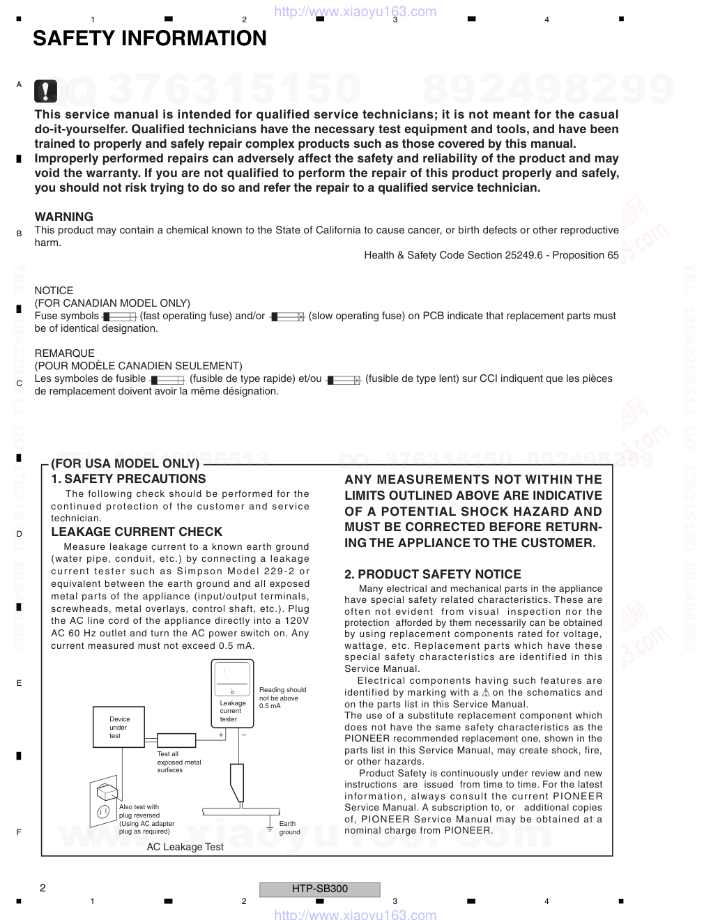
LEAKAGE CURRENT CHECK
Measure leakage current to a known earth ground
(water pipe, conduit, etc.) by connecting a leakage
current tester such as Simpson Model 229-2 or
equivalent between the earth ground and all exposed
metal parts of the appliance (input/output terminals,
screwheads, metal overlays, control shaft, etc.). Plug
the AC line cord of the appliance directly into a 120V
AC 60 Hz outlet and turn the AC power switch on. Any
current measured must not exceed 0.5 mA.
Device
under
test
Leakage
current
tester
Earth
ground
Reading should
not be above
0.5 mA
Also test with
plug reversed
(Using AC adapter
plug as required)
Test all
exposed metal
surfaces
AC Leakage Test
www. xiaoyu163. com
QQ 376315150
9
9
2
8
9
4
2
9
8
TEL 13942296513
9
9
2
8
9
4
2
9
8
0
5
1
5
1
3
6
7
3
Q
Q
TEL 13942296513 QQ 376315150 892498299
TEL 13942296513 QQ 376315150 892498299
http://www.xiaoyu163.com
3
HTP-SB300
5
6
7
8
5
6
7
8
A
B
C
D
E
F
[Important Check Points for Good Servicing]
In this manual, procedures that must be performed during repairs are marked with the below symbol.
Please be sure to confirm and follow these procedures.
1. Product safety
Please conform to product regulations (such as safety and radiation regulations), and maintain a safe servicing environment by
following the safety instructions described in this manual.
1 Use specified parts for repair.
Use genuine parts. Be sure to use important parts for safety.
2 Do not perform modifications without proper instructions.
Please follow the specified safety methods when modification(addition/change of parts) is required due to interferences such as
radio/TV interference and foreign noise.
3 Make sure the soldering of repaired locations is properly performed.
When you solder while repairing, please be sure that there are no cold solder and other debris.
Soldering should be finished with the proper quantity. (Refer to the example)
4 Make sure the screws are tightly fastened.
Please be sure that all screws are fastened, and that there are no loose screws.
5 Make sure each connectors are correctly inserted.
Please be sure that all connectors are inserted, and that there are no imperfect insertion.
6 Make sure the wiring cables are set to their original state.
Please replace the wiring and cables to the original state after repairs.
In addition, be sure that there are no pinched wires, etc.
7 Make sure screws and soldering scraps do not remain inside the product.
Please check that neither solder debris nor screws remain inside the product.
8 There should be no semi-broken wires, scratches, melting, etc. on the coating of the power cord.
Damaged power cords may lead to fire accidents, so please be sure that there are no damages.
If you find a damaged power cord, please exchange it with a suitable one.
9 There should be no spark traces or similar marks on the power plug.
When spark traces or similar marks are found on the power supply plug, please check the connection and advise on secure
connections and suitable usage. Please exchange the power cord if necessary.
a Safe environment should be secured during servicing.
When you perform repairs, please pay attention to static electricity, furniture, household articles, etc. in order to prevent injuries.
Please pay attention to your surroundings and repair safely.
2. Adjustments
To keep the original performance of the products, optimum adjustments and confirmation of characteristics within specification.
Adjustments should be performed in accordance with the procedures/instructions described in this manual.
4. Cleaning
For parts that require cleaning, such as optical pickups, tape deck heads, lenses and mirrors used in projection monitors, proper
cleaning should be performed to restore their performances.
3. Lubricants, Glues, and Replacement parts
Use grease and adhesives that are equal to the specified substance.
Make sure the proper amount is applied.
5. Shipping mode and Shipping screws
To protect products from damages or failures during transit, the shipping mode should be set or the shipping screws should be
installed before shipment. Please be sure to follow this method especially if it is specified in this manual.
www. xiaoyu163. com
QQ 376315150
9
9
2
8
9
4
2
9
8
TEL 13942296513
9
9
2
8
9
4
2
9
8
0
5
1
5
1
3
6
7
3
Q
Q
TEL 13942296513 QQ 376315150 892498299
TEL 13942296513 QQ 376315150 892498299
http://www.xiaoyu163.com
4
HTP-SB300
1
2
3
4
A
B
C
D
E
F
1
2
3
4
CONTENTS
SAFETY INFORMATION..........................................................................................................................................................2
1. SERVICE PRECAUTIONS....................................................................................................................................................5
1.1 NOTES ON SOLDERING ...............................................................................................................................................5
1.2 CAUTION........................................................................................................................................................................5
2. SPECIFICATIONS.................................................................................................................................................................6
2.1 SPECIFICATIONS ..........................................................................................................................................................6
2.2 PANEL FACILITIES.........................................................................................................................................................7
3. BASIC ITEMS FOR SERVICE.............................................................................................................................................11
3.1 CHECK POINTS AFTER SERVICING..........................................................................................................................11
3.2 PCB LOCATIONS .........................................................................................................................................................12
3.3 JIGS LIST......................................................................................................................................................................13
4. BLOCK DIAGRAM...............................................................................................................................................................14
4.1 OVERALL WIRING DIAGRAM .....................................................................................................................................14
4.2 BLOCK DIAGRAM ........................................................................................................................................................16
5. DIAGNOSIS.........................................................................................................................................................................18
5.1 DIAGNOSIS FLOWCHART ..........................................................................................................................................18
5.2 DESCRIPTION OF WIRELESS PAIRING OPERATIONS ............................................................................................21
5.3 SPECIFICATIONS FOR THE PROTECTION CIRCUITS .............................................................................................23
6. SERVICE MODE .................................................................................................................................................................24
7. DISASSEMBLY....................................................................................................................................................................25
8. EACH SETTING AND ADJUSTMENT ................................................................................................................................28
8.1 HOW TO UPDATE THE FIRMWARE............................................................................................................................28
9. EXPLODED VIEWS AND PARTS LIST...............................................................................................................................34
9.1 PACKING ......................................................................................................................................................................34
9.2 EXTERIOR SECTION (Main unit).................................................................................................................................36
9.3 EXTERIOR SECTION (Wireless subwoofer) ................................................................................................................38
10. SCHEMATIC DIAGRAM....................................................................................................................................................40
10.1 PWB(PCB) ASSY (FRONT/KEY)................................................................................................................................40
10.2 PWB(PCB) ASSY (MAIN)(1/2)....................................................................................................................................42
10.3 PWB(PCB) ASSY (MAIN)(2/2)....................................................................................................................................44
10.4 WIRELESS AUDIO TX ASSY.....................................................................................................................................46
10.5 PWB(PCB) ASSY (SW MAIN/LED) ............................................................................................................................48
10.6 PWB(PCB) ASSY (SMPS)..........................................................................................................................................50
10.7 WIRELESS AUDIO RX ASSY.....................................................................................................................................52
10.8 VOLTAGES and WAVEFORMS ..................................................................................................................................54
11. PCB CONNECTION DIAGRAM.........................................................................................................................................56
11.1 P.C.B SUB ASSY (INPUT) ..........................................................................................................................................56
11.2 PWB(PCB) ASSY (MAIN) ...........................................................................................................................................58
11.3 P.C.B SUB ASSY (HDMI)............................................................................................................................................60
11.4 PWB(PCB) ASSY (SW MAIN/LED).............................................................................................................................62
11.5 PWB(PCB) ASSY (SMPS) ..........................................................................................................................................64
11.6 WIRELESS AUDIO RX ASSY.....................................................................................................................................66
11.7 WIRELESS AUDIO TX ASSY .....................................................................................................................................67
12. PCB PARTS LIST ..............................................................................................................................................................68
www. xiaoyu163. com
QQ 376315150
9
9
2
8
9
4
2
9
8
TEL 13942296513
9
9
2
8
9
4
2
9
8
0
5
1
5
1
3
6
7
3
Q
Q
TEL 13942296513 QQ 376315150 892498299
TEL 13942296513 QQ 376315150 892498299
http://www.xiaoyu163.com
5
HTP-SB300
5
6
7
8
5
6
7
8
A
B
C
D
E
F
1. SERVICE PRECAUTIONS
1.1 NOTES ON SOLDERING
1.2 CAUTION
• For environmental protection, lead-free solder is used on the printed circuit boards mounted in this unit.
Be sure to use lead-free solder and a soldering iron that can meet specifications for use with lead-free solders for repairs
accompanied by reworking of soldering.
• Compared with conventional eutectic solders, lead-free solders have higher melting points, by approximately 40 ºC.
Therefore, for lead-free soldering, the tip temperature of a soldering iron must be set to around 373 ºC in general, although
the temperature depends on the heat capacity of the PC board on which reworking is required and the weight of the tip of
the soldering iron.
Do NOT use a soldering iron whose tip temperature cannot be controlled.
Compared with eutectic solders, lead-free solders have higher bond strengths but slower wetting times and higher melting
temperatures (hard to melt/easy to harden).
The following lead-free solders are available as service parts:
• Parts numbers of lead-free solder:
GYP1006 1.0 in dia.
GYP1007 0.6 in dia.
GYP1008 0.3 in dia.
Pairing main unit and subwoofer
1 After you’ve finished making the AC
adapter and power cord connections, press
STANDBY/ON on the main unit (see above).
2 Press on remote control.
3 While holding the main unit’s STEREO/
A.L.C. button depressed, simultaneously
press the remote control’s SHIFT and TV
CONTROL CH– buttons.
The indicator of the subwoofer light green, and
the pairing of main unit and subwoofer is
completed.
SYSTEM
SYSTEM
TV CONTROL
HDMI1
HDMI2
OPTICAL COAXIAL
CH
SOURCE
INPUT
INPUT
INPUT
ENTER
STANDBY/ON
INPUT
STEREO / A.L.C.
After replacement of the WIRELESS AUDIO ASSY (TX or RX), perform pairing between
the main unit and subwoofer.
www. xiaoyu163. com
QQ 376315150
9
9
2
8
9
4
2
9
8
TEL 13942296513
9
9
2
8
9
4
2
9
8
0
5
1
5
1
3
6
7
3
Q
Q
TEL 13942296513 QQ 376315150 892498299
TEL 13942296513 QQ 376315150 892498299
http://www.xiaoyu163.com
6
HTP-SB300
1
2
3
4
A
B
C
D
E
F
1
2
3
4
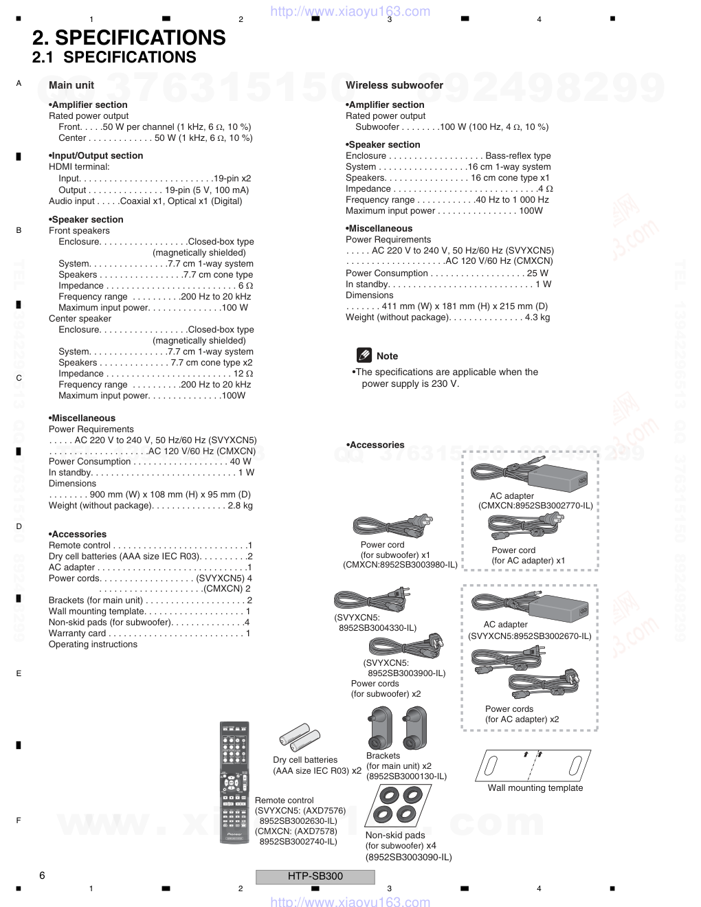
2. SPECIFICATIONS
2.1 SPECIFICATIONS
Main unit
•Amplifier section
Rated power output
Front. . . . .50 W per channel (1 kHz, 6 Ω, 10 %)
Center . . . . . . . . . . . . . 50 W (1 kHz, 6 Ω, 10 %)
•Input/Output section
HDMI terminal:
Input. . . . . . . . . . . . . . . . . . . . . . . . . . .19-pin x2
Output . . . . . . . . . . . . . . . 19-pin (5 V, 100 mA)
Audio input . . . . .Coaxial x1, Optical x1 (Digital)
•Speaker section
Front speakers
Enclosure. . . . . . . . . . . . . . . . . .Closed-box type
(magnetically shielded)
System. . . . . . . . . . . . . . . .7.7 cm 1-way system
Speakers . . . . . . . . . . . . . . . . .7.7 cm cone type
Impedance . . . . . . . . . . . . . . . . . . . . . . . . . . 6 Ω
Frequency range . . . . . . . . . .200 Hz to 20 kHz
Maximum input power. . . . . . . . . . . . . . .100 W
Center speaker
Enclosure. . . . . . . . . . . . . . . . . .Closed-box type
(magnetically shielded)
System. . . . . . . . . . . . . . . .7.7 cm 1-way system
Speakers . . . . . . . . . . . . . . 7.7 cm cone type x2
Impedance . . . . . . . . . . . . . . . . . . . . . . . . . 12 Ω
Frequency range . . . . . . . . . .200 Hz to 20 kHz
Maximum input power. . . . . . . . . . . . . . .100W
•Miscellaneous
Power Requirements
. . . . . AC 220 V to 240 V, 50 Hz/60 Hz (SVYXCN5)
. . . . . . . . . . . . . . . . . . . .AC 120 V/60 Hz (CMXCN)
Power Consumption . . . . . . . . . . . . . . . . . . . 40 W
In standby. . . . . . . . . . . . . . . . . . . . . . . . . . . . . 1 W
Dimensions
. . . . . . . . 900 mm (W) x 108 mm (H) x 95 mm (D)
Weight (without package). . . . . . . . . . . . . . . 2.8 kg
. . . . . . . . . . . . . . . . . . . .AC 120 V/60 Hz (CMXCN)
•Accessories
•Accessories
Remote control . . . . . . . . . . . . . . . . . . . . . . . . . . .1
Dry cell batteries (AAA size IEC R03). . . . . . . . . .2
AC adapter . . . . . . . . . . . . . . . . . . . . . . . . . . . . . .1
Power cords. . . . . . . . . . . . . . . . . . . (SVYXCN5) 4
. . . . . . . . . . . . . . . . . . . . .(CMXCN) 2
Brackets (for main unit) . . . . . . . . . . . . . . . . . . . . 2
Wall mounting template. . . . . . . . . . . . . . . . . . . . 1
Non-skid pads (for subwoofer). . . . . . . . . . . . . . .4
Warranty card . . . . . . . . . . . . . . . . . . . . . . . . . . . 1
Operating instructions
Wireless subwoofer
•Amplifier section
Rated power output
Subwoofer . . . . . . . .100 W (100 Hz, 4 Ω, 10 %)
•Speaker section
Enclosure . . . . . . . . . . . . . . . . . . . Bass-reflex type
System . . . . . . . . . . . . . . . . . .16 cm 1-way system
Speakers. . . . . . . . . . . . . . . . . 16 cm cone type x1
Impedance . . . . . . . . . . . . . . . . . . . . . . . . . . . . .4 Ω
Frequency range . . . . . . . . . . . .40 Hz to 1 000 Hz
Maximum input power . . . . . . . . . . . . . . . . 100W
•Miscellaneous
Power Requirements
. . . . . AC 220 V to 240 V, 50 Hz/60 Hz (SVYXCN5)
Power Consumption . . . . . . . . . . . . . . . . . . . 25 W
In standby. . . . . . . . . . . . . . . . . . . . . . . . . . . . . 1 W
Dimensions
. . . . . . . 411 mm (W) x 181 mm (H) x 215 mm (D)
Weight (without package). . . . . . . . . . . . . . . 4.3 kg
Note
•The specifications are applicable when the
power supply is 230 V.
SYSTEM
SYSTEM
TV CONTROL
HDMI1
HDMI2
OPTICAL
LISTENING MODE
COAXIAL
STANDARD
AUTO/
DIRECT
STEREO/
A.L.C.
ADV SURR
CH
VOL
BD MENU
DIMMER
DISPLAY
SURROUND SYSTEM
CH
CH
ENTER
ENTER
MUTE
SOURCE
INPUT
INPUT
INPUT
TV CODE
Remote control
(SVYXCN5: (AXD7576)
8952SB3002630-IL)
(CMXCN: (AXD7578)
8952SB3002740-IL)
Dry cell batteries
(AAA size IEC R03) x2
Wall mounting template
Power cords
(SVYXCN5:
8952SB3003900-IL)
(SVYXCN5:
8952SB3004330-IL)
(for subwoofer) x2
Brackets
(for main unit) x2
(8952SB3000130-IL)
Non-skid pads
(for subwoofer) x4
(8952SB3003090-IL)
Power cords
(for AC adapter) x2
AC adapter
(SVYXCN5:8952SB3002670-IL)
Power cord
(for subwoofer) x1
(CMXCN:8952SB3003980-IL)
Power cord
(for AC adapter) x1
AC adapter
(CMXCN:8952SB3002770-IL)
www. xiaoyu163. com
QQ 376315150
9
9
2
8
9
4
2
9
8
TEL 13942296513
9
9
2
8
9
4
2
9
8
0
5
1
5
1
3
6
7
3
Q
Q
TEL 13942296513 QQ 376315150 892498299
TEL 13942296513 QQ 376315150 892498299
http://www.xiaoyu163.com
7
HTP-SB300
5
6
7
8
5
6
7
8
A
B
C
D
E
F
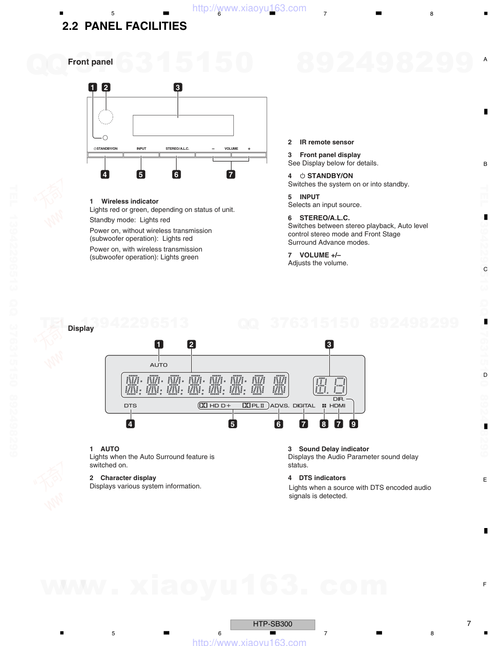
2.2 PANEL FACILITIES
Front panel
1
Lights red or green, depending on status of unit.
Standby mode: Lights red
Power on, without wireless transmission
(subwoofer operation): Lights red
Power on, with wireless transmission
(subwoofer operation): Lights green
2
3
See Display below for details.
4
STANDBY/ON
Switches the system on or into standby.
5
Wireless indicator
IR remote sensor
Front panel display
INPUT
Selects an input source.
6
STEREO/A.L.C.
Switches between stereo playback, Auto level
control stereo mode and Front Stage
Surround Advance modes.
7
VOLUME +/–
Adjusts the volume.
Display
1
Lights when the Auto Surround feature is
switched on.
2
Displays various system information.
3
Displays the Audio Parameter sound delay
status.
4
AUTO
Character display
Sound Delay indicator
DTS indicators
Lights when a source with DTS encoded audio
signals is detected.
STANDBY/ON
INPUT
STEREO /
E
M
U
L
O
V
.
C
.
L
.
A
1
2
4
5
6
7
3
1
2
4
5
6
7
8
7
9
3
www. xiaoyu163. com
QQ 376315150
9
9
2
8
9
4
2
9
8
TEL 13942296513
9
9
2
8
9
4
2
9
8
0
5
1
5
1
3
6
7
3
Q
Q
TEL 13942296513 QQ 376315150 892498299
TEL 13942296513 QQ 376315150 892498299
http://www.xiaoyu163.com
8
HTP-SB300
1
2
3
4
A
B
C
D
E
F
1
2
3
4
5
∂ D
Lights when a Dolby Digital encoded signal
is detected.
∂ D+
Lights when a source with Dolby Digital
Plus encoded audio signals is detected.
∂ HD
Lights when a source with Dolby TrueHD
encoded audio signals is detected.
∂ PLll
Lights to indicate ∂ Pro Logic II decoding
(see Listening in surround sound
for more on this).
6
Lights when one of the Advanced Surround
modes has been selected (see Using the
Advanced surround effects for more
on this).
7
DIGITAL
Lights when a digital audio signal is
selected.
Blinks when a digital audio signal is not
selected.
HDMI
Lights when an HDMI signal is selected.
Blinks when an HDMI signal is not
selected.
8
Lights when DIMMER is set to off.
9
Lights when the DIRECT or PURE DIRECT
mode is switched on.
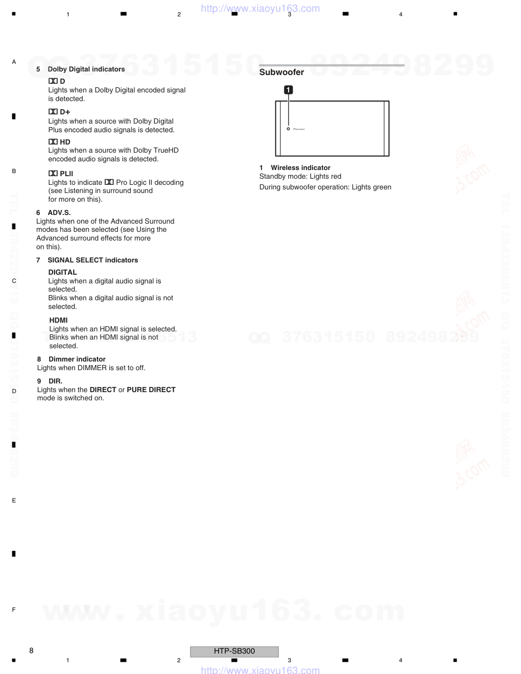
Subwoofer
1
Dolby Digital indicators
ADV.S.
SIGNAL SELECT indicators
Dimmer indicator
DIR.
Wireless indicator
Standby mode: Lights red
During subwoofer operation: Lights green
1
www. xiaoyu163. com
QQ 376315150
9
9
2
8
9
4
2
9
8
TEL 13942296513
9
9
2
8
9
4
2
9
8
0
5
1
5
1
3
6
7
3
Q
Q
TEL 13942296513 QQ 376315150 892498299
TEL 13942296513 QQ 376315150 892498299
http://www.xiaoyu163.com
9
HTP-SB300
5
6
7
8
5
6
7
8
A
B
C
D
E
F
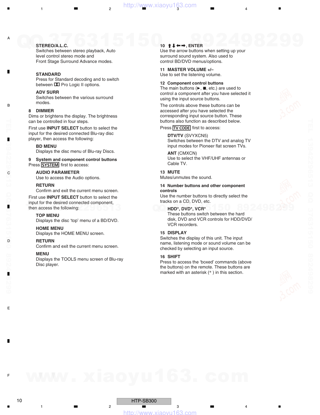
Remote control
1
SYSTEM
Switches the system between standby and on.
2
Switches the remote to control the system.
Also use to adjust the Audio parameters.
3
INPUT SELECT
Use to select the input source.
4
SOURCE
Press to turn on/off other components
connected to the system.
5
INPUT SELECT buttons
Use to select the input source. Switch the
remote control to operate any other components
allocated to the selected buttons (see
Controlling the rest of your system).
6
TV CONTROL buttons
These buttons are dedicated to control the TV
only have one TV to hook up to this system
Use to turn on/off the power of the TV.
INPUT
Use to select the TV input signal.
Press to select control of TV. Also use to
input a preset code allocated to the TV
CONTROL button.
CH +/–
Use to select channels.
VOL +/–
Use to adjust the volume on your TV.
7
Listening mode buttons
AUTO/DIRECT
Switches between Auto surround mode
(Auto playback on page20) and Stream
Direct playback. Stream Direct playback
bypasses the tone controls for the most
accurate reproduction of a source.
assigned to the button. Thus if you
assign it to the button.
SYSTEM
SYSTEM
TV CONTROL
HDMI1
HDMI2
OPTICAL
LISTENING MODE
COAXIAL
STANDARD
AUTO/
DIRECT
STEREO/
A.L.C.
ADV SURR
CH
VOL
BD MENU
DIMMER
DISPLAY
SURROUND SYSTEM
CH
CH
ENTER
ENTER
MUTE
SOURCE
INPUT
INPUT
INPUT
TV CODE
1
4
3
2
5
7
9
10
12
14
11
13
15
16
6
8
www. xiaoyu163. com
QQ 376315150
9
9
2
8
9
4
2
9
8
TEL 13942296513
9
9
2
8
9
4
2
9
8
0
5
1
5
1
3
6
7
3
Q
Q
TEL 13942296513 QQ 376315150 892498299
TEL 13942296513 QQ 376315150 892498299
http://www.xiaoyu163.com
10
HTP-SB300
1
2
3
4
A
B
C
D
E
F
1
2
3
4
STEREO/A.L.C.
Switches between stereo playback, Auto
level control stereo mode and
Front Stage Surround Advance modes.
STANDARD
Press for Standard decoding and to switch
between ∂ Pro Logic II options.
ADV SURR
Switches between the various surround
modes.
8
DIMMER
Dims or brightens the display. The brightness
can be controlled in four steps.
First use INPUT SELECT button to select the
input for the desired connected Blu-ray disc
player, then access the following:
BD MENU
Displays the disc menu of Blu-ray Discs.
9
System and component control buttons
AUDIO PARAMETER
Use to access the Audio options.
RETURN
Confirm and exit the current menu screen.
First use INPUT SELECT button to select the
input for the desired connected component,
then access the following:
TOP MENU
Displays the disc ‘top’ menu of a BD/DVD.
HOME MENU
Displays the HOME MENU screen.
RETURN
Confirm and exit the current menu screen.
MENU
Displays the TOOLS menu screen of Blu-ray
Disc player.
10 , ENTER
Use the arrow buttons when setting up your
surround sound system. Also used to
control BD/DVD menus/options.
11 MASTER VOLUME +/–
Use to set the listening volume.
12
The main buttons (, , etc.) are used to
control a component after you have selected it
using the input source buttons.
The controls above these buttons can be
accessed after you have selected the
corresponding input source button. These
buttons also function as described below.
DTV/TV (SVYXCN5)
Switches between the DTV and analog TV
input modes for Pioneer flat screen TVs.
ANT (CMXCN)
Use to select the VHF/UHF antennas or
Cable TV.
13 MUTE
Mutes/unmutes the sound.
14
Component control buttons
Number buttons and other component
controls
Use the number buttons to directly select the
tracks on a CD, DVD, etc.
HDD*, DVD*, VCR*
These buttons switch between the hard
disk, DVD and VCR controls for HDD/DVD/
VCR recorders.
15 DISPLAY
Switches the display of this unit. The input
name, listening mode or sound volume can be
checked by selecting an input source.
16 SHIFT
Press to access the ‘boxed’ commands (above
the buttons) on the remote. These buttons are
marked with an asterisk (* ) in this section.
Press first to access:
Press first to access:
www. xiaoyu163. com
QQ 376315150
9
9
2
8
9
4
2
9
8
TEL 13942296513
9
9
2
8
9
4
2
9
8
0
5
1
5
1
3
6
7
3
Q
Q
TEL 13942296513 QQ 376315150 892498299
TEL 13942296513 QQ 376315150 892498299
http://www.xiaoyu163.com
11
HTP-SB300
5
6
7
8
5
6
7
8
A
B
C
D
E
F
3. BASIC ITEMS FOR SERVICE
3.1 CHECK POINTS AFTER SERVICING
Item to be checked regarding video
Item to be checked regarding audio
Block noise
Distortion
Horizontal noise
Noise
Flicker
Volume too low
Disturbed image (video jumpiness)
Volume too high
Too dark
Volume fluctuating
Too bright
Sound interrupted
Mottled color
No.
Procedures
Check points
1
2
3
4
5
Confirm whether the customer complain has been solved.
If the customer complain occurs with the particular source,
such as Dolby Digital, DTS, AAC, DVD-A and HDMI, input it for
the operation check.
The customer complain must not be reappeared.
Video, Audio and operations must be normal.
Check the digital audio playback.
(Make the digital connections with a DVD player.)
Each channel audio and operations must be normal.
Check surround playback.
(Select Surround mode and check the multichannel operations
via the DSP circuit.)
Each channel audio and operations must be normal.
Check the video outputs.
(Connect with a DVD player.)
Video and operations must be normal.
Check the appearance of the product.
No scratches or dirt on its appearance after receiving it for
service.
Items to be checked after servicing
To keep the product quality after servicing, confirm recommended check points shown below.
See the table below for the items to be checked regarding video and audio.
www. xiaoyu163. com
QQ 376315150
9
9
2
8
9
4
2
9
8
TEL 13942296513
9
9
2
8
9
4
2
9
8
0
5
1
5
1
3
6
7
3
Q
Q
TEL 13942296513 QQ 376315150 892498299
TEL 13942296513 QQ 376315150 892498299
http://www.xiaoyu163.com
12
HTP-SB300
1
2
3
4
A
B
C
D
E
F
1
2
3
4
3.2 PCB LOCATIONS
D WIRELESS AUDIO TX ASSY
A PWB(PCB) ASSY
(FRONT/KEY)
C P.C.B SUB ASSY
(HDMI)
G WIRELESS AUDIO RX ASSY
E PWB(PCB) ASSY
(SW MAIN/LED)
F PWB(PCB) ASSY
(SMPS)
B PWB(PCB) ASSY
(MAIN)
Mark No. Description Part No.
LIST OF ASSEMBLIES
1..PWB(PCB) ASSY (FRONT/KEY)
8952SB3000490-IL
1..PWB(PCB) ASSY (MAIN)
8952SB3004380-IL
NSP
1..PWB(PCB)ASSY (HDMI)
7025HZ0902010-IL
2..P.C.B SUB ASSY (HDMI)
7028068701010-IL
1..WIRELESS AUDIO TX ASSY
8952SB3002510-IL
1..PWB(PCB) ASSY (SW MAIN/LED)
8952SB3004270-IL
1..PWB(PCB) ASSY (SMPS)
8952SB3003790-IL
1..WIRELESS AUDIO RX ASSY
8952SB3003750-IL
www. xiaoyu163. com
QQ 376315150
9
9
2
8
9
4
2
9
8
TEL 13942296513
9
9
2
8
9
4
2
9
8
0
5
1
5
1
3
6
7
3
Q
Q
TEL 13942296513 QQ 376315150 892498299
TEL 13942296513 QQ 376315150 892498299
http://www.xiaoyu163.com
13
HTP-SB300
5
6
7
8
5
6
7
8
A
B
C
D
E
F
3.3 JIGS LIST
Name
Jig No.
Remarks
RS-232C Interface jig
GGF1642
Firmware update
SB update tool
GGF1644
Firmware update
Adhesive
GYL-014
Silicon grease
GEM1057
Jigs list
www. xiaoyu163. com
QQ 376315150
9
9
2
8
9
4
2
9
8
TEL 13942296513
9
9
2
8
9
4
2
9
8
0
5
1
5
1
3
6
7
3
Q
Q
TEL 13942296513 QQ 376315150 892498299
TEL 13942296513 QQ 376315150 892498299
http://www.xiaoyu163.com
14
HTP-SB300
1
2
3
4
A
B
C
D
E
F
1
2
3
4
4. BLOCK DIAGRAM
4.1 OVERALL WIRING DIAGRAM
PN701
PN903
AC INLET
JACK1002
JACK1001
JACK1004
CN1001
JK101
SW501
SW502
SW503
SW504
JK102
JK103
CN1002
13PIN
FRONT PCB
KEY PCB
SUB-WOOFER
MAIN PCB
LED P
10PIN
4PIN
5PIN
5PIN
2PIN
2PIN
CENTER
SPEAKER
LEFT
SPEAKER
6ohm
12ohm
6PIN
CP702
LD701
CP1
CN104
CN105
CN103
CP101
CP102
PN901
F PWB(PCB) ASSY (SMPS)
(8952SB3003790-IL)
C P.C.B SUB ASSY
(HDMI)
(7028068701010-IL)
PWB(PCB) ASSY (FRONT/KE
(8952SB3000490-IL)
A 2/2
E 1/2
B 1/2-
www. xiaoyu163. com
QQ 376315150
9
9
2
8
9
4
2
9
8
TEL 13942296513
9
9
2
8
9
4
2
9
8
0
5
1
5
1
3
6
7
3
Q
Q
TEL 13942296513 QQ 376315150 892498299
TEL 13942296513 QQ 376315150 892498299
http://www.xiaoyu163.com
15
HTP-SB300
5
6
7
8
5
6
7
8
A
B
C
D
E
F
PN701
503
SW504
SW505
LD401
RMC401
MOD101
WIRELESS
TX MODULE
SOLDERING
CB
CB
SUB-WOOFER
MAIN PCB
LED PCB
8PIN
2PIN
2PIN
2PIN
12ohm
6ohm
4ohm
RIGHT
SPEAKER
CENTER
SPEAKER
CP701
3PIN
2PIN
CP702
LD701
CP703
WOOFER
SPEAKER
MOD701
WIRELESS
RX MODULE
SOLDERING
CP2
CP501
CP106
CP107
D WIRELESS AUDIO TX ASSY
(8952SB3002510-IL)
G WIRELESS AUDIO RX ASSY
(8952SB3003750-IL)
PWB(PCB) ASSY (FRONT/KEY)
(8952SB3000490-IL)
A 1/2
(FRONT/KEY)
0-IL)
PWB(PCB) ASSY (SW MAIN/LED)
(8952SB3004270-IL)
E 1/2
PWB(PCB) ASSY (SW MAIN/LED)
(8952SB3004270-IL)
E 2/2
PWB(PCB) ASSY (MAIN)
(8952SB3004380-IL)
B 1/2-2/2
www. xiaoyu163. com
QQ 376315150
9
9
2
8
9
4
2
9
8
TEL 13942296513
9
9
2
8
9
4
2
9
8
0
5
1
5
1
3
6
7
3
Q
Q
TEL 13942296513 QQ 376315150 892498299
TEL 13942296513 QQ 376315150 892498299
http://www.xiaoyu163.com
16
HTP-SB300
1
2
3
4
A
B
C
D
E
F
1
2
3
4
4.2 BLOCK DIAGRAM
F
G
E
C
B
JK102
JK101
JACK1001
CN1001
CN1002
JACK1002
JACK1004
IC101
IC104
Main unit
Wireless subwoofer
IC105
IC702
IC113
IC106
www. xiaoyu163. com
QQ 376315150
9
9
2
8
9
4
2
9
8
TEL 13942296513
9
9
2
8
9
4
2
9
8
0
5
1
5
1
3
6
7
3
Q
Q
TEL 13942296513 QQ 376315150 892498299
TEL 13942296513 QQ 376315150 892498299
http://www.xiaoyu163.com
17
HTP-SB300
5
6
7
8
5
6
7
8
A
B
C
D
E
F
A
D
C
C113
IC106
IC110
IC107
IC120
IC122
IC123
JACK1002
HDMI IN2
X1001
X1401
CN1001
CN1002
JACK1001
HDMI IN1
JACK1004
HDMI OUT
www. xiaoyu163. com
QQ 376315150
9
9
2
8
9
4
2
9
8
TEL 13942296513
9
9
2
8
9
4
2
9
8
0
5
1
5
1
3
6
7
3
Q
Q
TEL 13942296513 QQ 376315150 892498299
TEL 13942296513 QQ 376315150 892498299
http://www.xiaoyu163.com
18
HTP-SB300
1
2
3
4
A
B
C
D
E
F
1
2
3
4
5. DIAGNOSIS
5.1 DIAGNOSIS FLOWCHART
Power ON
Is not there abnormality for FL
or LED display?
After removing the PWB(PCB)
Assy (FRONT/KEY), is the
output voltage (L101) of IC116
(BD9702T) +5 V?
NG
NG
After opening R299 (0 ohm 3216),
are the pins 1-3 of IC119 (SI9407)
shorted to GND?
Replace the IC119 (SI9407).
Check the D106 (SS15), and
replace it if it is defective.
Is the voltage between pin 1 and
2 of CN104 +4.3 V?
NG
NG
Check the voltages (+5 V)
of CP101-pin 3 (Vcc5) and
MOD101-pin 1 (5 V).
NG
OK
OK
OK
Check the D105 (SS15), and
replace it if it is defective.
Is the voltage between pin 3 and
4 of CN104 -30 V?
NG
Replace the IC115 (KIA278R33).
Is the voltage between pin 4 and
5 of CN104 +3.3 V?
NG
Replace the IC112 (IL1117-3.3V)
Replace the IC124
(IL1117-3.3).
Is the voltage of IC112
(IL1117-3.3) +3.3 V?
After having input HDMI with HDMI
_Function, is "HDMI Flag ON"
displayed in FL?
NG
Is the voltage of pin 16 (Vcc) of
IC105 (74LVC257) 2.4 V?
Check the output waveforms
(FB117,FB118,FB119) of IC105
(74LVC257).
NG
Check the ZD104 (2.4 V
Zener) and FB116(Bead).
NG
Is the voltage of pin 1 (A/B) of IC105
(74LVC257) High (+3.3 V)?
Check pin 70(R245) of IC113
(MICOM) is High.
Replace it when it is Low.
NG
Replace the PWB(PCB) Assy
(FRONT/KEY), then check it.
OK
OK
OK
OK
OK
OK
OK
OK
OK
Replace the PWB(PCB) Assy
(HDMI), the check it.
Check the connection of MICOM
communication port of PWB(PCB)
Assy(HDMI) and PWB(PCB) Assy
(MAIN). (CSSK_MAIN, SCDO_
MAIN, SCDI_MAIN,SUB_RESET,
SUBPDN, MAIN_IRQ, SUB_IRQ,
SUB_ON)
NG
OK
NG
Replace the PWB(PCB) Assy
(HDMI), the check it.
Check the waveforms of CP101-
pin 4(HDMI_SD0), pin 5(HDMI_
SD1), pin 8(HDMI_LRCK), pin 9
(HDMI_BCK), pin10(HDMI_MCLK).
Check audio output after HDMI input.
Note: Input signal uses Dolby 5.1ch
source.
NG
OK
Is the output voltage of
IC124 (IL1117-3.3)
+3.3 V?
Check the waveforms of IC106
(DA788_DSP)-pins 113 (R145)
and 116 (R146).
NG
Check it after opening
FB111 and FB129.
Check the existence of short-circuit
of DSP_3.3V and the DSP_1.2V in
the power supply section.
NG
NG
Replace the IC108 and
IC109 (IL1117-1.2).
OK
Is the output voltage of
IC108,109 (IL1117-1.2)
+1.2 V?
Check it after opening
FB112.
Check the existence of short-circuit
of DSP_1.2V in the power supply
section.
NG
NG
Replace the
IC104(CS8422).
OK
Check the XMCK wave-
form of pin 17(R164) of
IC106 (DA788_DSP).
Check the power supply
(FB105) of IC104 (CS8422).
Check the output waveform of
X101 (24.576 MHz).
NG
Check the DSP Firmware Version.
(SET STEREO KEY+RMC DIMMER KEY)
When "DSP:_:_ _:_ _" is
displayed, replace the IC110.
NG
NG
OK
OK
OK
TROUBLESHOOTING
B
A
www. xiaoyu163. com
QQ 376315150
9
9
2
8
9
4
2
9
8
TEL 13942296513
9
9
2
8
9
4
2
9
8
0
5
1
5
1
3
6
7
3
Q
Q
TEL 13942296513 QQ 376315150 892498299
TEL 13942296513 QQ 376315150 892498299
http://www.xiaoyu163.com
19
HTP-SB300
5
6
7
8
5
6
7
8
A
B
C
D
E
F
Is the voltage of pin 88(TAS_OTW)
of IC113 (MICOM) High (3.3 V)?
Is the voltage of pin 14(R320)
(TAS5508 MUTE) of IC120
(TAS5508) High (3.3 V)?
NG
After opening R376 of pin 2(OTW)
of IC122, is the voltage of pin 88
(TAS_OTW) of IC113 (MICOM)
High (3.3 V)?
NG
Replace the IC122(TAS5342A).
OK
OK
Check the output waveform of
IC104(CS8422)-pin 1 (C104).
NG
Is the output voltage of IC101
(74AHCU04)-pin 14 (VCC33) +3.3 V?
NG
Check the FB133.
NG
OK
OK
OK
Check audio output after COAXIAL
input.
Note: Input signal uses Dolby 5.1ch
source.
Replace the
IC104(CS8422).
OK
OK
Check pin 58(R235) of IC113(MICOM)
is High.Replace it when it is Low.
NG
NG
OK
OK
Check the waveform of X103
(13.5 MHz).
Replace the X103 (13.5 MHz).
Check the output waveforms of
IC120(TAS5508)-pins 40,41,42,
43,51 and 52 (PWM Output).
NG
Replace the IC122 or IC123
(TAS5342A).
Check the output waveforms of IC122(TAS5342A)
-pins 39,36,33,28 and IC123(TAS5342A)-pins
39,36.
NG
NG
After opening R338,R339,R340,
R341,R342 and R343 of IC120
(TAS5508)-pins 40,41,42,43,
51 and 52, check the waveform.
OK
Replace the IC122 or IC123
(TAS5342A).
Replace the IC120(TAS5508).
NG
OK
Replace the L102,L103 and
L104.
Check the I2S output waveform of
IC104(CS8422)-pins 27(FB110),
28(FB109),29(FB108) and 31
(FB107).
Is the voltage of pin 32
(R106) (RESET) of IC104
(CS8422) High (3.3 V)?
NG
After opening R106, is the
voltage of pin 32 of IC104
(CS8422) High (3.3 V)?
Replace the
IC113(MICOM).
OK
OK
Replace the
IC104(CS8422).
Replace the
IC104(CS8422).
NG
NG
Check the waveforms of
I2C communication port
of IC104(CS8422)-pins 9
(R109) and 10(R110).
Check the waveforms of I2C
communication port of IC113
(MICOM)-pins 59(R236) and
60(R237).
OK
Check the waveforms of IC101
(74AHCU04)-pin 13(Coaxial Input).
Check the Coaxial Input
circuit.
NG
OK
Replace the IC101(74AHCU04).
Check the waveforms of output
(FB117,FB118,FB119) of
IC105 (74LVC257).
Is the voltage of pin 1(A/B) of
IC105 (74LVC257) Low (0 V)?
NG
Check pin 70(R245) of IC113
(MICOM) is Low.
Replace it when it is High.
NG
OK
Replace the FB107,FB108,
FB109 and FB110.
Check the output waveform after
openig CP106 and CP107.
Replace the Speaker Unit.
NG
OK
B
A
C
www. xiaoyu163. com
QQ 376315150
9
9
2
8
9
4
2
9
8
TEL 13942296513
9
9
2
8
9
4
2
9
8
0
5
1
5
1
3
6
7
3
Q
Q
TEL 13942296513 QQ 376315150 892498299
TEL 13942296513 QQ 376315150 892498299
http://www.xiaoyu163.com
20
HTP-SB300
1
2
3
4
A
B
C
D
E
F
1
2
3
4
Check the waveform of SPDIF
output of JK102-pin 3(input).
NG
NG
OK
OK
Check audio output after OPTICAL
input.
Note: Input signal uses Dolby 5.1ch
source.
Check the waveform of IC104
(CS8422)-pin 2(C105).
Replace the
IC701(IL1117-3.3).
OK
Replace the
IC703(KIA7027).
NG
Replace the IC104(CS8422).
NG
Replace the MOD101 Wireless
TX Module.
After Re-pairing operation (press the STEREO key (main
unit), SHIFT key (remote control unit),then TV CH- key
(remote control unit) after pressing the SYSTEM key (remote
control unit)), does GREEN LED of FRONT blink at intervals
of 250 msec?
NG
NG
OK
OK
OK
Do LEDs of Wireless Subwoofer
and PWB (PCB) Assy (FRONT/
KEY) light in GREEN?
After turned OFF the power supply
of Subwoofer and then ON, check
the GREEN LED lights.
Check the voltages of CP702-pin 1
(+5 V) and CP702-pin 6(+31 V) of
PWB(PCB) Assy (SW MAIN/LED).
NG
Replace the PWB(PCB) Assy
(SMPS).
NG
Is the voltage of MOD701-pin 2
(+5 V) 5 V?
Check the FB711.
NG
OK
OK
OK
Is the voltage of MOD701-pin 9
(MOD_RESET) High (3.3 V)?
Is the voltage of IC703(KIA7027)
-pin 1(3.3 V) 3.3 V?
NG
Is the voltage of MOD701-pin 3
(GREEN_LED) High (3.3 V)?
Replace the MOD701
Wireless RX Module.
NG
OK
Is the voltage of CP701-pin 3
(GREEN) High (3.3 V)?
Replace the
Q702(2SC2412K).
NG
Replace the
IC104(CS8422).
NG
OK
Is the voltage of CP703-pin 3
(GREEN) High (3.3 V)?
Replace the Connector Assy
of 3 Pin LED PCB.
NG
Replace the LD701
(RED/GREEN Dual LED).
OK
Replace the JK102 Optical Jack.
Check the I2S waveforms of MOD101
-pins 7(I2S_DATA),8(I2S_LRCK) and
12(I2S_BCK).
NG
NG
OK
OK
Check the subwoofer audio output
after OPTICAL input.
Note: Input signal uses Dolby 5.1ch
source.
After initialization (press the STEREO
key and HDMI1 key (main unit)),
turn the AC POWER OFF.
Check the waveforms of IC104(CS8422)
-pins 23(R120),24(R121) and 25(R122).
Replace the R120,R121,R122 and
R307,R308,R309.
Replace the MOD701
Wireless RX Module.
NG
OK
Check the waveforms of I2C communi-
cation port of MOD701-pins 15 and 16.
Replace the IC702(STA326).
Replace the IC702(STA326).
Replace the MOD701
Wireless RX Module.
NG
OK
Check the I2S output waveforms of
MOD701-pins 8(MCLK),12(SDATA),
13(LRCK) and 14(BCK) of Subwoofer.
NG
OK
After opening R706,R708,R709 and
R710, check the I2S output wavefrm of
MOD701-pins 8,12,13 and 14.
Check the output waveforms of IC702
(STA326)-pins 3 and 16(PWM Output).
NG
OK
Replace the L701.
Replace the Speaker Unit.
After opening PN701, check the
output wavefrm.
NG
OK
C
www. xiaoyu163. com
QQ 376315150
9
9
2
8
9
4
2
9
8
TEL 13942296513
9
9
2
8
9
4
2
9
8
0
5
1
5
1
3
6
7
3
Q
Q
TEL 13942296513 QQ 376315150 892498299
TEL 13942296513 QQ 376315150 892498299
http://www.xiaoyu163.com
21
HTP-SB300
5
6
7
8
5
6
7
8
A
B
C
D
E
F
5.2 DESCRIPTION OF WIRELESS PAIRING OPERATIONS
Descriptions of Wireless Modes
1. Factory Mode
• Factory-set initial status
• The LED indications are as follows:
• To enter Factory Mode
TX (Sound Bar block)
1. Set TX to Power ON status then press the MUTE Key on
the remote control while holding the STEREO Key on
the main unit pressed.
2. The FL display shows “FACTORY MODE.”
3. The red and green LEDs blink alternately at intervals of
500 ms.
RX (Subwoofer block)
1. Operate TX and RX in Normal Mode.
2. When you set TX to Factory Mode from the state of 1
above, RX also automatically enters Factory Mode.
• How to shift from Factory Mode to Normal Mode
1. After Factory Mode is entered, once turn the power off
(setting TX to Standby status and RX to AC OFF status).
2. When you turn TX and RX back on, they enter Auto
Pairing Mode then shift to Normal Mode after several
seconds.
2. Normal Mode
• Normal operation status
• The LED indications are as follows:
• This mode can be entered in the following conditions:
1. When TX and RX are turned on in Factory Mode (The ID
of RX is changed to that of TX.)
2. When TX and RX are turned on with the same ID.
• This mode can be entered in the following conditions:
1. When only TX is in Power ON status while RX is in
Power OFF status
2. When only RX is in Power ON status while TX is in
Standby status
3. When TX and RX differ in ID although both are in Power
ON status
3. Standby Mode
• Status where TX and RX are searching for each other
• The LED indications are as follows:
4. Re-Pairing (Manual Pairing) Mode
• Mode to normally operate TX and RX differing in ID.
(Use this mode if any module replacement has
occurred in servicing, etc.)
• The LED indications are as follows:
• To enter the mode
TX (Sound Bar block)
1. With TX in Power ON status, simultaneously press the
SHIFT key and the CH- key for TV CONTROL on the
remote control.
2. The green LED blinks at intervals of 250 ms.
RX (Subwoofer block)
1. RX starts Re-Pairing operation upon power on and
continues it for 15 seconds at maximum. The method of
Pairing with TX is as follows:
2. After the above-mentioned TX enters Re-Pairing Mode
(green LED blinking) with the Power Cord of RX
disconnected, connect the AC power to RX.
-> If pairing with TX fails: RX enters Standby Mode 15
seconds after it is turned on (red LED ON).
-> When pairing with TX is successful: RX immediately
enters Normal Mode (green LED ON).
• If Re-Pairing is started for TX in Factory Mode
1. The green LED blinks at intervals of 250 ms.
2. Re-Pairing Mode is maintained for 60 seconds at
maximum. The mode changes to Standby Mode after 60
seconds (red LED ON).
500 ms Toggle Blinking
500 ms Toggle Blinking
RED
RX (Sub Woofer)
TX (Sound Bar)
LED COLOR
GREEN
OFF
OFF
ON
ON
RED
RX (Sub Woofer)
TX (Sound Bar)
LED COLOR
GREEN
5. Sleep Mode (Power Save Mode)
• Standby Mode is entered if no audio signal of a
subwoofer channel is sent from TX to RX for 10
minutes.
• The LED indications are as follows:
• If any audio signal of a subwoofer channel is sent to TX
in Sleep Mode, the mode automatically changes to
Normal Play Mode.
ON
ON
OFF
OFF
RED
RX (Sub Woofer)
TX (Sound Bar)
LED COLOR
GREEN
OFF
OFF
500 ms Blink
250 ms Blink
RED
RX (Sub Woofer)
TX (Sound Bar)
LED COLOR
GREEN
ON
ON
OFF
OFF
RED
RX (Sub Woofer)
TX (Sound Bar)
LED COLOR
GREEN
www. xiaoyu163. com
QQ 376315150
9
9
2
8
9
4
2
9
8
TEL 13942296513
9
9
2
8
9
4
2
9
8
0
5
1
5
1
3
6
7
3
Q
Q
TEL 13942296513 QQ 376315150 892498299
TEL 13942296513 QQ 376315150 892498299
http://www.xiaoyu163.com
22
HTP-SB300
1
2
3
4
A
B
C
D
E
F
1
2
3
4
In a case where both TX and RX stay in Factory Mode (not yet having entered Normal Mode after factory delivery)
-> Regardless of the order of power ON, pairing is enabled.
Factory Mode TX
(Sound Bar)
Factory Mode RX (Sub Woofer)
GREEN & RED LED 500 ms Toggle Blink
Factory Mode RX (Sub Woofer)
GREEN & RED LED 500 ms Toggle Blink
Condition 1
Pairing Methods in Various Conditions
In a case where TX enters Standby Mode after pairing with RX has once been established and RX is in Factory Mode
-> Pairing is not possible in this state.
-> Methods for Re-Pairing
Method 1) Set TX to Factory Mode.
Method 2) Disconnect the AC power to RX then connect it again after setting TX to Re-Pairing Mode.
RED LED ON
Standby Mode TX
(TX that once paired with RX)
Condition 2
In a case where the module of TX or RX has been repaired or replaced
-> The procedure of Re-Pairing in a case where TX and RX have different IDs because of repair or replacement is as follows:
1. Set TX to Re-Pairing Mode. The green LED of TX blinks at intervals of 250 ms for 1 minute.
2. Disconnect the power to RX then connect it again. The green LED of RX blinks at intervals of 500 ms.
When pairing with the above-mentioned TX in Re-Pairing Mode is established successfully, the green LED lights.
3. Re-Pairing Mode of TX is canceled immediately when pairing with RX is established.
4. RX of ID:B obtains the same ID as that of TX after pairing with TX.
NG
TX (ID: A)
(POWER ON)
RX (ID: B)
(POWER ON)
Condition 3
www. xiaoyu163. com
QQ 376315150
9
9
2
8
9
4
2
9
8
TEL 13942296513
9
9
2
8
9
4
2
9
8
0
5
1
5
1
3
6
7
3
Q
Q
TEL 13942296513 QQ 376315150 892498299
TEL 13942296513 QQ 376315150 892498299
http://www.xiaoyu163.com
23
HTP-SB300
5
6
7
8
5
6
7
8
A
B
C
D
E
F
5.3 SPECIFICATIONS FOR THE PROTECTION CIRCUITS
Protection Activation Conditions for the Sound Bar Adapter
On the Protection Functions of the Sound Bar
On the Protection Functions of the Subwoofer
The DC output from the adapter will be shut off if the 24-V DC output load becomes 6.4 A (max. current limitation) or
higher (based on 90-V AC power).
1. Protection Activation Conditions for the TAS5342A
• Max. current limitation: 7.1 A or higher
• /OTW: If the temperature becomes 125 °C or higher, the Over Temperature Protection function will be activated.
• /SD: In a case of undervoltage or overload, the Shutdown Protection will be activated.
In a case of excess current or excess temperature at the AMP IC (IC702: STA326), the protection function will be
activated then deactivated in the AMP IC, according to the internally set programmable recovery time (100 ms), as shown
below:
1) After a shutdown, the PWM output will be OFF for 100 msec (the set recovery time).
2) The system will enter Normal mode to detect operating conditions.
3) If the condition that caused the shutdown still remains, the protection function will be reactivated, according to the set
recovery time.
No LED display nor power-off operation will be activated in the subwoofer while the protection function is activated.
Therefore, if no sound is output even if the LED is lit in green, the protection function may have been activated.
2. Over Temperature Protection (MICOM Pin 88)
• In Normal Operation mode: High
In a case where the temperature of the AMP IC (IC122 or IC123) becomes 125 °C or higher: Low
The signal from Pin 14 of IC120 (TAS5508) is set to low in order to mute the PWM output.
Muting of the PWM output is canceled when /OTW is returned to high.
3. On the AMP Shutdown Protection Function (AMP IC [IC122, IC123] Pin 5) (/SD)
• In Normal Operation mode: High
• In a case of undervoltage or overload: Low
When this signal is input to the MICOM, the audio signal will be muted and the system will enter STANDBY mode.
0
0
Over temperature (OTE) or overload (OLP) or under voltage (UVP)
0
1
Overload (OLP) or under voltage (UVP)
1
0
Junction temperature higher than 125 °C (over temperature warning)
1
1
Junction temperature lower than 100 °C and no OLP or UVP faults (normal operation)
SD
OTW
IC113 (MICOM)
Pin 86 (/TAS_MUTE)
High → Low
High → Low
Pin 88 (/TAS_OTW)
Description
1
2
IC120 (TAS5508)
Pin 14 (/TAS_MUTE)
IC122 (TAS5342A)
Pin 2 (/OTW)
IC123 (TAS5342A)
Pin 2 (/OTW)
IC113 (MICOM)
High → Low
STANDBY
Pin 89 (/TAS_SD)
1
2
IC122 (TAS5342A)
Pin 5 (/SD)
IC123 (TAS5342A)
Pin 5 (/SD)
www. xiaoyu163. com
QQ 376315150
9
9
2
8
9
4
2
9
8
TEL 13942296513
9
9
2
8
9
4
2
9
8
0
5
1
5
1
3
6
7
3
Q
Q
TEL 13942296513 QQ 376315150 892498299
TEL 13942296513 QQ 376315150 892498299
http://www.xiaoyu163.com
24
HTP-SB300
1
2
3
4
A
B
C
D
E
F
1
2
3
4
6. SERVICE MODE
There is no information to be shown in this chapter.
www. xiaoyu163. com
QQ 376315150
9
9
2
8
9
4
2
9
8
TEL 13942296513
9
9
2
8
9
4
2
9
8
0
5
1
5
1
3
6
7
3
Q
Q
TEL 13942296513 QQ 376315150 892498299
TEL 13942296513 QQ 376315150 892498299
http://www.xiaoyu163.com
25
HTP-SB300
5
6
7
8
5
6
7
8
A
B
C
D
E
F
7. DISASSEMBLY
(1) Remove the Grille frame.
Note: The catch and front panel and the catch and
boss are bonded with adhesive (2 places).
See the figure at right.
(2) Remove the eight screws.
[1] Front and Center speaker (Main unit)
1
1
2
2
2
2
2
2
2
2
Panel Front
Grille Frame
Catch
Grille Frame
Panel Front
(3) Remove the five screws on the HDMI PCB.
(4) Remove the six screws on the MAIN PCB.
MAIN PCB
HDMI PCB
MAIN PCB
HDMI PCB
3
3 4
4
4
3 4
4
4
3
3
Note: The photo shows the state with the shield
plate removed.
www. xiaoyu163. com
QQ 376315150
9
9
2
8
9
4
2
9
8
TEL 13942296513
9
9
2
8
9
4
2
9
8
0
5
1
5
1
3
6
7
3
Q
Q
TEL 13942296513 QQ 376315150 892498299
TEL 13942296513 QQ 376315150 892498299
http://www.xiaoyu163.com
26
HTP-SB300
1
2
3
4
A
B
C
D
E
F
1
2
3
4
版权声明
1. 本站所有素材,仅限学习交流,仅展示部分内容,如需查看完整内容,请下载原文件。
2. 会员在本站下载的所有素材,只拥有使用权,著作权归原作者所有。
3. 所有素材,未经合法授权,请勿用于商业用途,会员不得以任何形式发布、传播、复制、转售该素材,否则一律封号处理。
4. 如果素材损害你的权益请联系客服QQ:77594475 处理。