先锋PIONEER GM-X432音响电路图
 "先锋PIONEER GM-X432音响电路图-0")
 "先锋PIONEER GM-X432音响电路图-1")
 "先锋PIONEER GM-X432音响电路图-2")
 "先锋PIONEER GM-X432音响电路图-3")
 "先锋PIONEER GM-X432音响电路图-4")
 "先锋PIONEER GM-X432音响电路图-5")
 "先锋PIONEER GM-X432音响电路图-6")
 "先锋PIONEER GM-X432音响电路图-7")
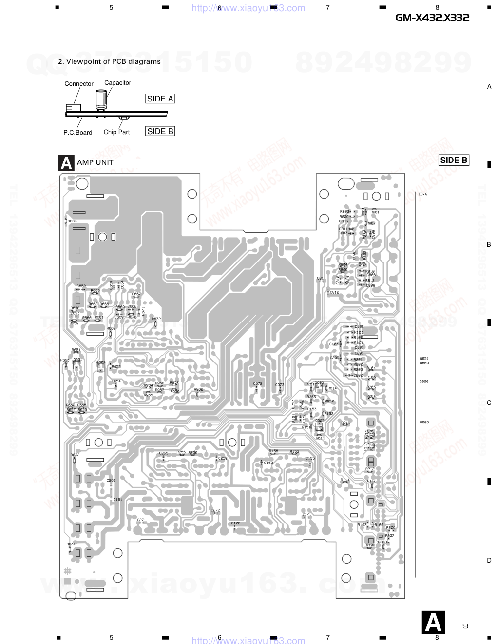 "先锋PIONEER GM-X432音响电路图-8")
 "先锋PIONEER GM-X432音响电路图-9")
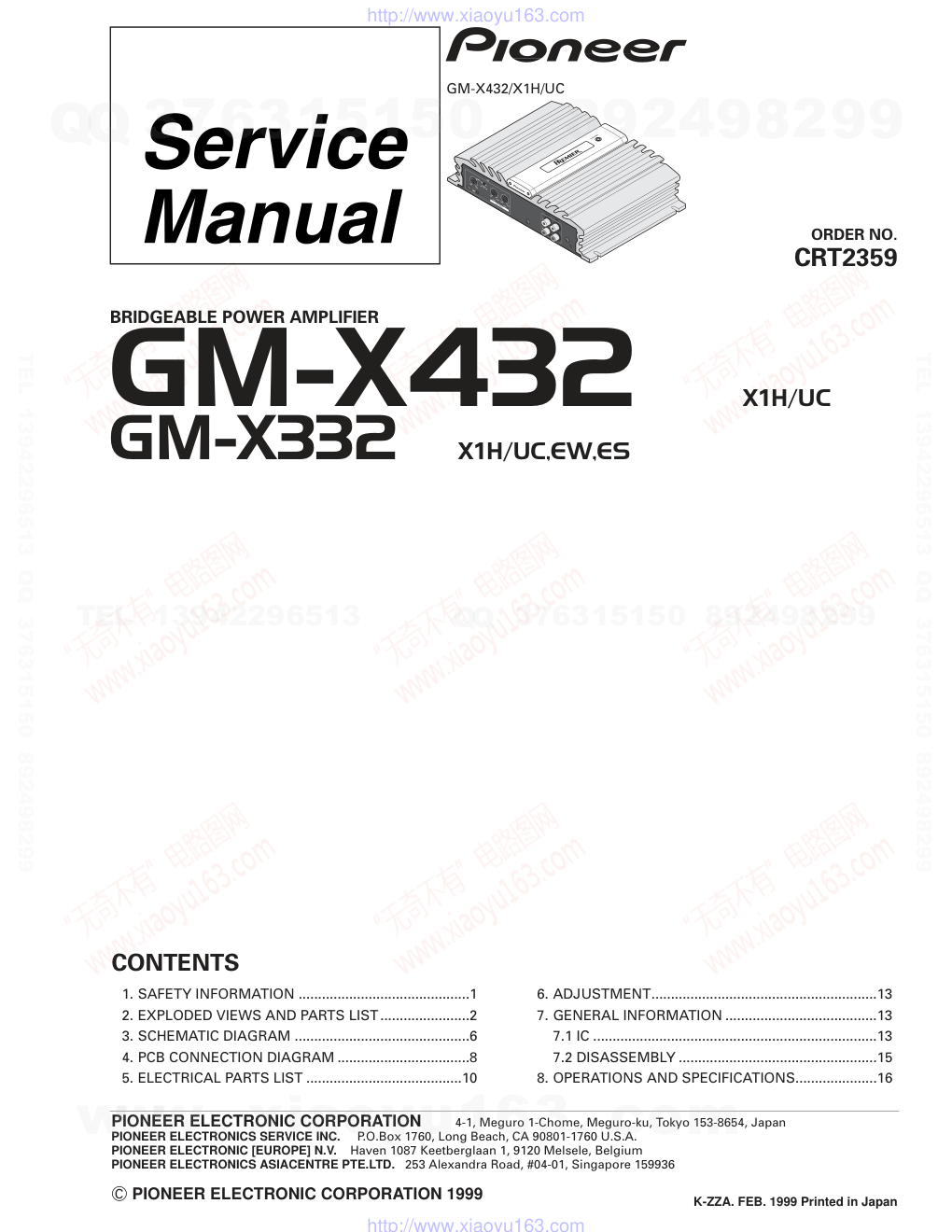
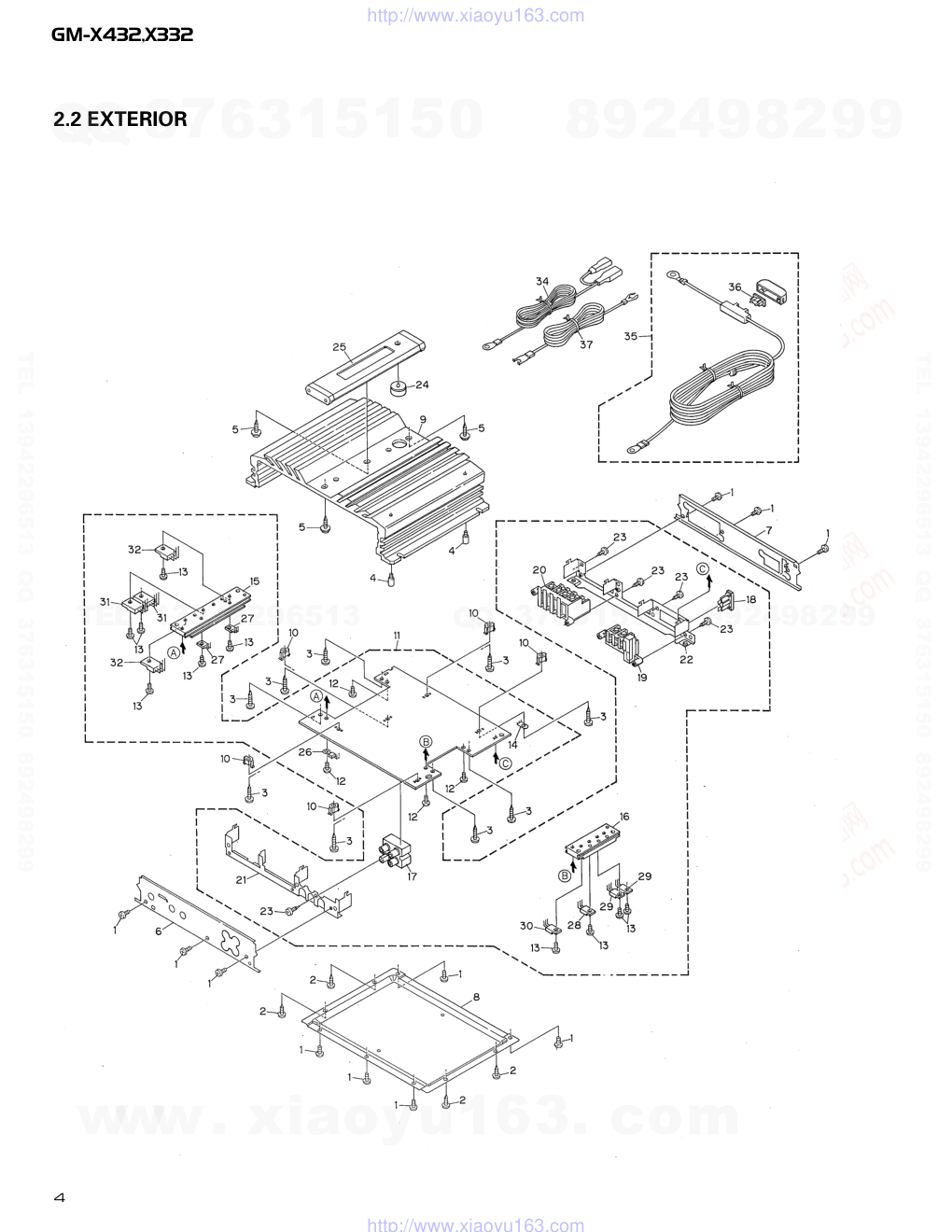
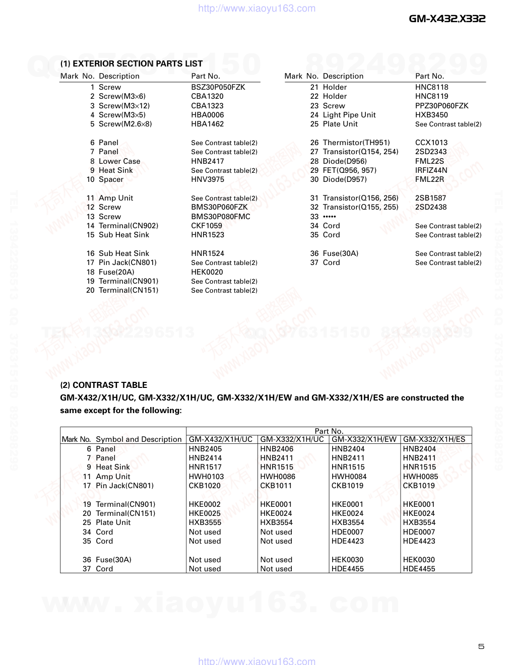
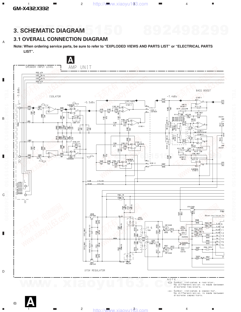
PIONEER ELECTRONIC CORPORATION 4-1, Meguro 1-Chome, Meguro-ku, Tokyo 153-8654, Japan PIONEER ELECTRONICS SERVICE INC. P.O.Box 1760, Long Beach, CA 90801-1760 U.S.A. PIONEER ELECTRONIC [EUROPE] N.V. Haven 1087 Keetberglaan 1, 9120 Melsele, Belgium PIONEER ELECTRONICS ASIACENTRE PTE.LTD. 253 Alexandra Road, #04-01, Singapore 159936 C PIONEER ELECTRONIC CORPORATION 1999 K-ZZA. FEB. 1999 Printed in Japan CONTENTS 1. SAFETY INFORMATION ............................................1 2. EXPLODED VIEWS AND PARTS LIST.......................2 3. SCHEMATIC DIAGRAM .............................................6 4. PCB CONNECTION DIAGRAM ..................................8 5. ELECTRICAL PARTS LIST ........................................10 6. ADJUSTMENT..........................................................13 7. GENERAL INFORMATION .......................................13 7.1 IC .........................................................................13 7.2 DISASSEMBLY ...................................................15 8. OPERATIONS AND SPECIFICATIONS.....................16 ORDER NO. CRT2359 BRIDGEABLE POWER AMPLIFIER GM-X432�X1H/UC GM-X332�X1H/UC,EW,ES GM-X432/X1H/UC www. xiaoyu163. com QQ 376315150 9 9 2 8 9 4 2 9 8 TEL 13942296513 9 9 2 8 9 4 2 9 8 0 5 1 5 1 3 6 7 3 Q Q TEL 13942296513 QQ 376315150 892498299 TEL 13942296513 QQ 376315150 892498299 http://www.xiaoyu163.com 2 GM-X432,X332 CAUTION This service manual is intended for qualified service technicians; it is not meant for the casual do-it-yourselfer. Qualified technicians have the necessary test equipment and tools, and have been trained to properly and safely repair complex products such as those covered by this manual. Improperly performed repairs can adversely affect the safety and reliability of the product and may void the warranty. If you are not qualified to perform the repair of this product properly and safely; you should not risk trying to do so and refer the repair to a qualified service technician. WARNING This product contains lead in solder and certain electrical parts contain chemicals which are known to the state of California to cause cancer, birth defects or other reproductive harm. Health & Safety Code Section 25249.6 - Proposition 65 2. EXPLODED VIEWS AND PARTS LIST 2.1 PACKING 8 11 9 10 1 2 7 5 4 6 3 1. SAFETY INFORMATION - GM-X432/X1H/UC, GM-X332/X1H/UC www. xiaoyu163. com QQ 376315150 9 9 2 8 9 4 2 9 8 TEL 13942296513 9 9 2 8 9 4 2 9 8 0 5 1 5 1 3 6 7 3 Q Q TEL 13942296513 QQ 376315150 892498299 TEL 13942296513 QQ 376315150 892498299 http://www.xiaoyu163.com 3 GM-X432,X332 NOTE: - Parts marked by “*” are generally unavailable because they are not in our Master Spare Parts List. - Screws adjacent to ∇ mark on the product are used for disassembly. 1 Screw BYC40P180FZK 2 Polyethylene Bag HEG0011 3 Polyethylene Bag HEG0010 4 Carton See Contrast table(2) 5 Contain Box See Contrast table(2) 6 Protector HHP0048 7-1 Owner’s Manual See Contrast table(2) 7-2 Owner’s Manual See Contrast table(2) * 7-3 Warranty Card See Contrast table(2) * 7-4 Card See Contrast table(2) * 7-5 PRC See Contrast table(2) 8 Cord Assy See Contrast table(2) 9 Cord(Remote) See Contrast table(2) 10 Cord(Power) See Contrast table(2) 11 Cord(Ground) See Contrast table(2) Mark No. Description Part No. (1) PACKING SECTION PARTS LIST - Owner’s Manual Model Part No. Language GM-X432/X1H/UC HRD0081 English, French GM-X332/X1H/UC HRD0080 English, French GM-X332/X1H/EW HRD0082 English, Spanish, German, French, Italian, Dutch GM-X332/X1H/ES HRD0083 English, Spanish HRD0084 Portuguese(B), Arabic Part No. Mark No. Symbol and Description GM-X432/X1H/UC GM-X332/X1H/UC GM-X332/X1H/EW GM-X332/X1H/ES 4 Carton HHG0197 HHG0180 HHG0182 HHG0183 5 Contain Box HHL0197 HHL0180 HHL0182 HHL0183 7-1 Owner’s Manual HRD0081 HRD0080 HRD0082 HRD0083 7-2 Owner’s Manual Not used Not used Not used HRD0084 * 7-3 Warranty Card HRY1070 Not used HRY1087 Not used * 7-4 Card Not used ARY1048 Not used Not used * 7-5 PRC HRY0007 HRY0007 Not used Not used 8 Cord Assy Not used Not used HDW0004 HDW0004 9 Cord(Remote) Not used Not used HDE0007 HDE0007 10 Cord(Power) Not used Not used HDE4423 HDE4423 11 Cord(Ground) Not used Not used HDE4455 HDE4455 (2) CONTRAST TABLE GM-X432/X1H/UC, GM-X332/X1H/UC, GM-X332/X1H/EW and GM-X332/X1H/ES are constructed the same except for the following: www. xiaoyu163. com QQ 376315150 9 9 2 8 9 4 2 9 8 TEL 13942296513 9 9 2 8 9 4 2 9 8 0 5 1 5 1 3 6 7 3 Q Q TEL 13942296513 QQ 376315150 892498299 TEL 13942296513 QQ 376315150 892498299 http://www.xiaoyu163.com 4 GM-X432,X332 2.2 EXTERIOR www. xiaoyu163. com QQ 376315150 9 9 2 8 9 4 2 9 8 TEL 13942296513 9 9 2 8 9 4 2 9 8 0 5 1 5 1 3 6 7 3 Q Q TEL 13942296513 QQ 376315150 892498299 TEL 13942296513 QQ 376315150 892498299 http://www.xiaoyu163.com 5 GM-X432,X332 1 Screw BSZ30P050FZK 2 Screw(M3×6) CBA1320 3 Screw(M3×12) CBA1323 4 Screw(M3×5) HBA0006 5 Screw(M2.6×8) HBA1462 6 Panel See Contrast table(2) 7 Panel See Contrast table(2) 8 Lower Case HNB2417 9 Heat Sink See Contrast table(2) 10 Spacer HNV3975 11 Amp Unit See Contrast table(2) 12 Screw BMS30P060FZK 13 Screw BMS30P080FMC 14 Terminal(CN902) CKF1059 15 Sub Heat Sink HNR1523 16 Sub Heat Sink HNR1524 17 Pin Jack(CN801) See Contrast table(2) 18 Fuse(20A) HEK0020 19 Terminal(CN901) See Contrast table(2) 20 Terminal(CN151) See Contrast table(2) 21 Holder HNC8118 22 Holder HNC8119 23 Screw PPZ30P060FZK 24 Light Pipe Unit HXB3450 25 Plate Unit See Contrast table(2) 26 Thermistor(TH951) CCX1013 27 Transistor(Q154, 254) 2SD2343 28 Diode(D956) FML22S 29 FET(Q956, 957) IRFIZ44N 30 Diode(D957) FML22R 31 Transistor(Q156, 256) 2SB1587 32 Transistor(Q155, 255) 2SD2438 33 ••••• 34 Cord See Contrast table(2) 35 Cord See Contrast table(2) 36 Fuse(30A) See Contrast table(2) 37 Cord See Contrast table(2) (1) EXTERIOR SECTION PARTS LIST Mark No. Description Part No. Mark No. Description Part No. Part No. Mark No. Symbol and Description GM-X432/X1H/UC GM-X332/X1H/UC GM-X332/X1H/EW GM-X332/X1H/ES 6 Panel HNB2405 HNB2406 HNB2404 HNB2404 7 Panel HNB2414 HNB2411 HNB2411 HNB2411 9 Heat Sink HNR1517 HNR1515 HNR1515 HNR1515 11 Amp Unit HWH0103 HWH0086 HWH0084 HWH0085 17 Pin Jack(CN801) CKB1020 CKB1011 CKB1019 CKB1019 19 Terminal(CN901) HKE0002 HKE0001 HKE0001 HKE0001 20 Terminal(CN151) HKE0025 HKE0024 HKE0024 HKE0024 25 Plate Unit HXB3555 HXB3554 HXB3554 HXB3554 34 Cord Not used Not used HDE0007 HDE0007 35 Cord Not used Not used HDE4423 HDE4423 36 Fuse(30A) Not used Not used HEK0030 HEK0030 37 Cord Not used Not used HDE4455 HDE4455 (2) CONTRAST TABLE GM-X432/X1H/UC, GM-X332/X1H/UC, GM-X332/X1H/EW and GM-X332/X1H/ES are constructed the same except for the following: www. xiaoyu163. com QQ 376315150 9 9 2 8 9 4 2 9 8 TEL 13942296513 9 9 2 8 9 4 2 9 8 0 5 1 5 1 3 6 7 3 Q Q TEL 13942296513 QQ 376315150 892498299 TEL 13942296513 QQ 376315150 892498299 http://www.xiaoyu163.com GM-X432,X332 1 2 3 4 1 2 3 4 D C B A 3. SCHEMATIC DIAGRAM 3.1 OVERALL CONNECTION DIAGRAM Note: When ordering service parts, be sure to refer to “EXPLODED VIEWS AND PARTS LIST” or “ELECTRICAL PARTS LIST”. A 6 A www. xiaoyu163. com QQ 376315150 9 9 2 8 9 4 2 9 8 TEL 13942296513 9 9 2 8 9 4 2 9 8 0 5 1 5 1 3 6 7 3 Q Q TEL 13942296513 QQ 376315150 892498299 TEL 13942296513 QQ 376315150 892498299 http://www.xiaoyu163.com GM-X432,X332 5 6 7 8 5 6 7 8 D C B A 7 A www. xiaoyu163. com QQ 376315150 9 9 2 8 9 4 2 9 8 TEL 13942296513 9 9 2 8 9 4 2 9 8 0 5 1 5 1 3 6 7 3 Q Q TEL 13942296513 QQ 376315150 892498299 TEL 13942296513 QQ 376315150 892498299 http://www.xiaoyu163.com 8 GM-X432,X332 1 2 3 4 1 2 3 4 D C B A 4. PCB CONNECTION DIAGRAM 4.1 AMP UNIT NOTE FOR PCB DIAGRAMS 1. The parts mounted on this PCB include all necessary parts for several destination. For further information for respective destinations, be sure to check with the schematic dia- gram. A A AMP UNIT SIDE A www. xiaoyu163. com QQ 376315150 9 9 2 8 9 4 2 9 8 TEL 13942296513 9 9 2 8 9 4 2 9 8 0 5 1 5 1 3 6 7 3 Q Q TEL 13942296513 QQ 376315150 892498299 TEL 13942296513 QQ 376315150 892498299 http://www.xiaoyu163.com GM-X432,X332 5 6 7 8 5 6 7 8 D C B A 9 A 2. Viewpoint of PCB diagrams Capacitor Connector P.C.Board Chip Part SIDE A SIDE B A AMP UNIT SIDE B www. xiaoyu163. com QQ 376315150 9 9 2 8 9 4 2 9 8 TEL 13942296513 9 9 2 8 9 4 2 9 8 0 5 1 5 1 3 6 7 3 Q Q TEL 13942296513 QQ 376315150 892498299 TEL 13942296513 QQ 376315150 892498299 http://www.xiaoyu163.com 10 GM-X432,X332 5. ELECTRICAL PARTS LIST NOTES: - Parts whose parts numbers are omitted are subject to being not supplied. - The part numbers shown below indicate chip components. Chip Resistor RS1/_S___J,RS1/__S___J Chip Capacitor (except for CQS.....) CKS....., CCS....., CSZS..... =====Circuit Symbol and No.===Part Name Part No. --- ------ ------------------------------------------ ------------------------- Unit Number : HWH0103(GM-X432/X1H/UC) Unit Number : HWH0086(GM-X332/X1H/UC) Unit Number : HWH0084(GM-X332/X1H/EW) Unit Number : HWH0085(GM-X332/X1H/ES) Unit Name : Amp Unit MISCELLANEOUS IC 101 IC NJM2068L IC 102 IC NJM2068L IC 103 IC NJM2068L IC 104 IC NJM2068L IC 151 IC NJM2068L IC 651 IC PA2027A IC 801 IC NJM2068D IC 802 IC NJM2068D IC 951 IC UPC494C Q 151 Transistor 2SA1145 Q 152 Transistor 2SC2705 Q 154 Transistor 2SD2343 Q 155 Transistor 2SD2438 Q 156 Transistor 2SB1587 Q 251 Transistor 2SA1145 Q 252 Transistor 2SC2705 Q 254 Transistor 2SD2343 Q 255 Transistor 2SD2438 Q 256 Transistor 2SB1587 Q 601 Transistor 2SD1768S Q 602 Transistor 2SD1768S Q 605 Transistor 2SC2412K Q 606 Transistor 2SC2412K Q 609 Transistor DTA124EK Q 651 Transistor 2SA1037K Q 652 Transistor 2SC1740S Q 653 Transistor 2SC1740S Q 654 Transistor 2SC1740S Q 655 Transistor 2SA933S Q 656 Transistor 2SC1740S Q 657 Transistor 2SA933S Q 658 Transistor 2SB1243 Q 951 Transistor DTA114ES Q 952 Transistor 2SA933S Q 953 Transistor 2SA933S Q 956 FET IRFIZ44N Q 957 FET IRFIZ44N Q 960 Transistor 2SD1864 Q 961 Transistor 2SB1243 D 601 Diode 1SS133 D 602 Diode 1SS133 D 651 Diode 1SS133 D 652 Diode HZS7L(A2) D 653 Diode 1SS133 D 654 LED SML210LT(LMN) D 901 Diode ERA15-02VH D 902 Diode ERA15-02VH D 951 Diode 1SS133 D 954 Diode 1SS133 D 955 Diode 1SS133 D 956 Diode FML22S D 957 Diode FML22R D 958 Diode HZS16L(1) D 959 Diode HZS16L(1) L 801 Ferri-Inductor CTF1007 L 802 Ferri-Inductor CTF1007 L 901 Choke Coil 50µH(Idc=3A) CTH1218 T 951 Transformer CTT1091 TH 951 Thermistor CCX1013 TH 953 Thermistor CCX1035 S 101 Switch(OFF/LPF/HPF) CSH1029 S 951 Switch(BFC) See Contrast table VR 101 Volume 10kΩ(A) CCS1241 VR 102 Volume 10kΩ(C) CCS1240 VR 103 Volume 50kΩ(C) See Contrast table Fuse 20A HEK0020 RESISTORS R 101 RS1/10S153J R 102 RS1/10S153J R 103 RS1/10S153J R 104 RS1/10S123J R 105 RS1/10S223J R 107 RS1/10S222J R 108 RS1/10S181J R 111 RS1/10S102J R 112 RS1/10S101J R 113 RD1/4PU221J R 114 See Contrast table R 115 See Contrast table R 151 RS1/10S222J R 152 RS1/10S822J R 153 RS1/10S471J R 154 RS1/10S223J R 155 RS1/10S153J R 156 RS1/10S153J R 157 RD1/4PU561J R 158 RD1/4PU561J R 159 RD1/4PU161J R 160 RD1/4PU161J R 161 RD1/4PU473J R 162 RD1/4PU473J R 163 RD1/4PU221J R 164 RD1/4PU562J R 165 RD1/4PU222J R 166 RD1/4PU473J R 167 RD1/4PU473J R 168 0.22Ω CCN1013 =====Circuit Symbol and No.===Part Name Part No. --- ------ ------------------------------------------ ------------------------- A www. xiaoyu163. com QQ 376315150 9 9 2 8 9 4 2 9 8 TEL 13942296513 9 9 2 8 9 4 2 9 8 0 5 1 5 1 3 6 7 3 Q Q TEL 13942296513 QQ 376315150 892498299 TEL 13942296513 QQ 376315150 892498299 http://www.xiaoyu163.com 11 GM-X432,X332 R 169 0.22Ω CCN1013 R 170 0.22Ω CCN1013 R 171 0.22Ω CCN1013 R 172 RD1/2PM100J R 201 RS1/10S153J R 202 RS1/10S153J R 203 RS1/10S153J R 204 RS1/10S123J R 205 RS1/10S223J R 207 RS1/10S222J R 208 RS1/10S181J R 211 RS1/10S102J R 212 RS1/10S101J R 213 RD1/4PU221J R 214 See Contrast table R 215 See Contrast table R 251 RS1/10S222J R 252 RS1/10S822J R 253 RS1/10S471J R 254 RS1/10S223J R 255 RS1/10S153J R 256 RS1/10S153J R 257 RD1/4PU561J R 258 RD1/4PU561J R 259 RD1/4PU161J R 260 RD1/4PU161J R 261 RD1/4PU473J R 262 RD1/4PU473J R 263 RD1/4PU221J R 264 RD1/4PU562J R 265 RD1/4PU222J R 266 RD1/4PU473J R 267 RD1/4PU473J R 268 0.22Ω CCN1013 R 269 0.22Ω CCN1013 R 270 0.22Ω CCN1013 R 271 0.22Ω CCN1013 R 272 RD1/2PM100J R 601 RD1/4PU393J R 602 RD1/4PU393J R 605 RD1/4PU564J R 606 RD1/4PU564J R 609 RD1/2PM473J R 610 RD1/2PM473J R 613 RS1/10S472J R 614 RS1/10S472J R 651 RS1/10S104J R 652 RS1/10S103J R 653 RS1/10S472J R 654 RD1/4PU392J R 655 RS1/10S472J R 656 RS1/10S222J R 657 RS1/10S221J R 658 RS1/10S102J R 659 RS1/10S473J R 660 RS1/10S103J R 661 RS1/10S103J R 662 RS1/10S222J R 663 RS1/10S472J R 664 RD1/4PU392J R 665 RS1/10S392J R 666 RS1/10S103J R 667 RS1/10S472J R 668 RS1/10S473J R 669 RS1/10S223J R 670 RS1/10S223J R 671 RS1/10S223J R 672 RS1/10S472J R 673 RD1/4PU101J R 674 RD1/4PU221J R 675 RD1/4PU152J R 676 RD1/2PM681J R 801 RS1/10S471J R 802 RS1/10S471J R 803 RS1/10S223J R 804 RS1/10S223J R 805 RN1/4PC1002D R 806 (RN1/10SE1002D) GGC1320 R 807 (RN1/10SE1002D) GGC1320 R 808 (RN1/10SE1002D) GGC1320 R 809 RS1/10S104J R 810 RS1/10S104J R 811 (RN1/10SE1002D) GGC1320 R 812 (RN1/10SE1002D) GGC1320 R 813 (RN1/10SE1002D) GGC1320 R 814 (RN1/10SE1002D) GGC1320 R 831 RS1/10S473J R 832 RS1/10S473J R 953 RD1/4PU392J R 954 RD1/4PU101J R 955 RS1/10S153J R 956 RS1/10S102J R 957 RS1/10S153J R 958 See Contrast table R 959 RD1/4PU101J R 960 RD1/4PU332J R 961 RD1/4PU101J R 962 RS1/10S332J R 963 RS1/10S472J R 964 RS1/10S472J R 965 RS1/10S472J R 966 RD1/4PU272J R 967 RD1/4PU272J R 969 RD1/4PU221J R 972 RD1/2PM560J R 973 RD1/4PU560J R 976 RD1/4PU220J R 977 RD1/4PU220J R 978 RD1/2PM220J R 979 RD1/2PM220J R 980 RD1/4PU100J R 981 RD1/4PU100J R 982 RD1/4PU472J R 983 RD1/4PU472J CAPACITORS C 101 CKSYB184K16 C 102 CKSYB474K16 C 103 CKSQYB273K50 C 104 CFTLA124J50 C 105 CFTLA124J50 C 106 CFTLA273J50 C 107 CEAS4R7M50 C 108 CFTLA334J50 C 151 CEAS101M10 C 152 CCSQSL680J50 C 153 CFTLA224J50 C 154 CFTLA224J50 C 155 CCSQCH220J50 C 156 CCPUSL330J50 C 157 CCPUSL330J50 =====Circuit Symbol and No.===Part Name Part No. --- ------ ------------------------------------------ ------------------------- =====Circuit Symbol and No.===Part Name Part No. --- ------ ------------------------------------------ ------------------------- www. xiaoyu163. com QQ 376315150 9 9 2 8 9 4 2 9 8 TEL 13942296513 9 9 2 8 9 4 2 9 8 0 5 1 5 1 3 6 7 3 Q Q TEL 13942296513 QQ 376315150 892498299 TEL 13942296513 QQ 376315150 892498299 http://www.xiaoyu163.com 12 GM-X432,X332 C 158 CCSQCH220J50 C 159 CFTLA223J50 C 160 CFTLA333J50 C 161 CKSYB104K50 C 201 CKSYB184K16 C 202 CKSYB474K16 C 203 CKSQYB273K50 C 204 CFTLA124J50 C 205 CFTLA124J50 C 206 CFTLA273J50 C 207 CEAS4R7M50 C 208 CFTLA334J50 C 251 CEAS101M10 C 252 CCSQSL680J50 C 253 CFTLA224J50 C 254 CFTLA224J50 C 255 CCSQCH220J50 C 256 CCPUSL330J50 C 257 CCPUSL330J50 C 258 CCSQCH220J50 C 259 CFTLA223J50 C 260 CFTLA333J50 C 261 CKSYB104K50 C 651 220µF/10V CCH1036 C 652 CKSYB103K50 C 653 CKSQYB103K50 C 654 CKSQYB103K50 C 655 CEAS100M16 C 656 CEAS100M16 C 657 CEAS101M16 C 658 CKSQYB103K50 C 659 CKSQYB103K50 C 660 CEAS220M16 C 661 470µF/16V CCH1183 C 662 CKSQYB103K50 C 663 CQMA223J50 C 801 CKSQYB471K50 C 802 CKSQYB471K50 C 803 CEAS100M16 C 804 CEAS100M16 C 805 CKSQYB472K50 C 806 CKSQYB472K50 C 807 CCSQCH470J50 C 808 CCSQCH470J50 C 809 CCSQCH470J50 C 810 CCSQCH470J50 C 811 CKSQYB103K50 C 812 CKSQYB103K50 C 831 CEAS100M16 C 832 CEAS100M16 C 901 CFTLA224J50 C 951 CEAS100M16 C 952 CEAS221M10 C 953 CQMA102J50 C 954 CEAS2R2M50 C 955 CEAS101M16 C 956 3300µF/16V CCH1130 C 958 CQMA472J50 C 959 CQMA472J50 C 960 CQMA102J50 C 961 CQMA102J50 C 962 3300µF/35V CCH1200 C 963 3300µF/35V CCH1200 C 968 CEAS101M35 C 969 CEAS101M35 C 970 CEAS100M50 C 971 CEAS100M50 C 972 CKSQYB473K50 C 973 CKSQYB473K50 =====Circuit Symbol and No.===Part Name Part No. --- ------ ------------------------------------------ ------------------------- =====Circuit Symbol and No.===Part Name Part No. --- ------ ------------------------------------------ ------------------------- www. xiaoyu163. com QQ 376315150 9 9 2 8 9 4 2 9 8 TEL 13942296513 9 9 2 8 9 4 2 9 8 0 5 1 5 1 3 6 7 3 Q Q TEL 13942296513 QQ 376315150 892498299 TEL 13942296513 QQ 376315150 892498299 http://www.xiaoyu163.com 13 GM-X432,X332 7. GENERAL INFORMATION 7.1 PARTS 7.1.1 IC 6. ADJUSTMENT There is no information to be shown in this chapter. A OUTPUT V+ B OUTPUT B -INPUT B +INPUT V- A +INPUT A -INPUT + + 1 2 3 4 5 6 7 8 NJM2068L Part No. Symbol and Description GM-X432/X1H/UC GM-X332/X1H/UC GM-X332/X1H/EW GM-X332/X1H/ES S 951 Switch(BFC) Not used Not used HSH-156 HSH-156 VR 103 Volume 50kΩ(C) CCS1242 Not used CCS1242 CCS1242 R 114 RS1/10S512J Not used RS1/10S512J RS1/10S512J R 115 Not used RS1/10S223J Not used Not used R 214 RS1/10S512J Not used RS1/10S512J RS1/10S512J R 215 Not used RS1/10S223J Not used Not used R 958 Not used Not used RS1/10S105J RS1/10S105J CONTRAST TABLE of AMP UNIT GM-X432/X1H/UC, GM-X332/X1H/UC, GM-X332/X1H/EW and GM-X332/X1H/ES are constructed the same except for the following: www. xiaoyu163. com QQ 376315150 9 9 2 8 9 4 2 9 8 TEL 13942296513 9 9 2 8 9 4 2 9 8 0 5 1 5 1 3 6 7 3 Q Q TEL 13942296513 QQ 376315150 892498299 TEL 13942296513 QQ 376315150 892498299 http://www.xiaoyu163.com 14 GM-X432,X332 1 2 3 4 5 6 7 8 9 10 11 12 13 14 15 16 VCC Stby DET1 DET2 DET_R GND NC NC IN1 IN2 IN3 Cont_V Filter Vs_out TC Mute_out + - zz 2V + - zz 2V + - zz 2V + - 2V zz + - 2V 20µA + - zz 2V + - zz 50µA 4.7kΩ Transient voltage detector Bandgap Circuit motion:on + - 5.6V + - Q S R Oneshot (1µsec) Bandgap:on Switch:on 0.13V PA2027A www. xiaoyu163. com QQ 376315150 9 9 2 8 9 4 2 9 8 TEL 13942296513 9 9 2 8 9 4 2 9 8 0 5 1 5 1 3 6 7 3 Q Q TEL 13942296513 QQ 376315150 892498299 TEL 13942296513 QQ 376315150 892498299 http://www.xiaoyu163.com 15 GM-X432,X332 7.2 DIAGNOSIS 7.2.1 DISASSEMBLY - Removing the Case(not shown) 1. Remove the nine screws. 2. Remove the Case. - Removing the Panel Unit(not shown) 1. Remove the six screws. 2. Remove the two Panel Units. - Removing the Amp Unit(Fig.1) Remove the nine screws. Use 2 pcs. of screw and insert them into the two holes marked with an arrow. Alternately tighten them little by little until the Sub Heat Sink separates from the Heat Sink. Amp Unit Sub Heat Sink Heat Sink Sub Heat Sink Fig.1 www. xiaoyu163. com QQ 376315150 9 9 2 8 9 4 2 9 8 TEL 13942296513 9 9 2 8 9 4 2 9 8 0 5 1 5 1 3 6 7 3 Q Q TEL 13942296513 QQ 376315150 892498299 TEL 13942296513 QQ 376315150 892498299 http://www.xiaoyu163.com 16 GM-X432,X332 8. OPERATIONS AND SPECIFICATIONS 8.1 OPERATIONS Setting the Unit LPF (Low-Pass Filter)/HPF (High-Pass Filter) Select Switch Set the LPF/HPF select switch as follows according to the type of the speaker that is connected to the speaker output connector and the car stereo system: LPF/HPF Select Audio frequency range Speaker Remarks Switch to be output Type LPF (left) Very-low-frequency range Sub-woofer Connect a sub-woofer. OFF (center) Full range Full range HPF (right) Low-frequency range to Full range If you want to cut the very- high-frequency range low-frequency range because it is not necessary for the speaker you use. Gain Control If the sound is too low, even when the volume of the car stereo used along with this power amplifier is turned up, turn gain control on the back of the power amplifier clockwise. If the sound distorts when the volume is turned up, turn the gain control counter-clockwise. • When using with an RCA equipped car stereo (standard output of 500 mV), set to the NORMAL position. When using with an RCA equipped Pioneer car stereo with max. output of 4 V or more, set to the MIN position. • If you hear too much noise when using the speaker input terminals, turn the gain control counter-clockwise. Power Indicator The power indicator lights when the power is switched on. Bass Boost Level Control Bass boost level control can boost the level around the frequency selected by the bass boost frequency control from 0 to 12 dB. Bass Boost Frequency Control You can select a bass boost frequency from 40 to 120 Hz with the bass boost control. • Bass Boost Level Control, Bass Boost Frequency Control can be adjusted only when the LPF/HPF select switch is set to a position other than HPF. www. xiaoyu163. com QQ 376315150 9 9 2 8 9 4 2 9 8 TEL 13942296513 9 9 2 8 9 4 2 9 8 0 5 1 5 1 3 6 7 3 Q Q TEL 13942296513 QQ 376315150 892498299 TEL 13942296513 QQ 376315150 892498299 http://www.xiaoyu163.com 17 GM-X432,X332 To prevent damage • Do not ground the speaker wire directly or con- nect a negative (–) lead wire for several speakers. • This unit is for vehicles with a 12-volt battery and negative grounding. Before installing it in a recre- ational vehicle, truck, or bus, check the battery voltage. • If the car stereo is kept on for a long time while the engine is at rest or idling, the battery may go dead. Turn the car stereo off when the engine is at rest or idling. • If the system remote control wire of the amplifier is connected to the power terminal through the ignition switch (12 V DC), the amplifier will always be on when the ignition is on— regardless of whether the car stereo is on or off. Because of this, the battery could go dead if the engine is at rest or idle. • Install and route the sold separately battery wire as far away as possible from the speaker wires. Install and route the sold separately battery wire and ground wire, speaker wires, and the amplifier as far away as possible from the antenna, antenna cable and tuner. • Speakers to be connected to the amplifier should conform with the standards listed below. Otherwise damage will occur to the speaker. The speaker impedance must be 1 to 8 ohms. (2 to 8 Ω for stereo, monaural and other bridge connec- tions.) Connection Diagram Connecting the Unit CAUTION • Remove the negative (–) terminal of the battery to avoid the risk of short-circuit and damage to the unit. • Secure the wiring with cable clamps or adhesive tape. To protect the wiring, wrap adhesive tape around them where they lie against metal parts. • Do not route wires where they will get hot, for example where the heater will blow over them. If the insulation heats up, it may become damaged, resulting in a short-circuit through the vehicle body. • Make sure that wires will not interfere with moving parts of the vehicle, such as the gearshift, handbrake or seat sliding mechanism. • Do not shorten any wires. Otherwise the protec- tion circuit may fail to work when it should. • Never feed power to other equipment by cutting the insulation of the power supply wire to tap from the wire. The current capacity of the wire will be exceeded, causing overheating. Speaker Channel Speaker Type Power Two-channel Sub-woofer Nominal input: Min. 35 W Other than sub-woofer Max. input: Min. 70 W One-channel Sub-woofer Nominal input: Min. 100 W Other than sub-woofer Max. input: Min. 200 W Fuse (30 A) Grommet RCA input (sold separately) Special red battery wire [RD-222] (sold separately). After making all other connections at the amplifier, connect the battery wire terminal of the amplifier to the positive (+) terminal of the battery. Ground wire (black) [RD-222] (sold separately). Connect to metal body or chassis. Amplifier with RCA input jacks Fuse (20 A) Car stereo with RCA output jacks Connecting wires with RCA pin plugs (sold separately). RCA output jack Speaker terminal See the “Connecting the Speaker wires” section for speaker connection instructions. System remote control wire (sold separately) Connect the male terminal of this wire to the system remote con- trol terminal of the car stereo (SYSTEM REMOTE CONTROL). The female terminal can be connected to the auto-antenna relay control terminal. If the car stereo does not have a system remote control terminal, connect the male terminal to the power terminal through the ignition switch. RCA input jack External Output www. xiaoyu163. com QQ 376315150 9 9 2 8 9 4 2 9 8 TEL 13942296513 9 9 2 8 9 4 2 9 8 0 5 1 5 1 3 6 7 3 Q Q TEL 13942296513 QQ 376315150 892498299 TEL 13942296513 QQ 376315150 892498299 http://www.xiaoyu163.com GM-X432,X332 8.2 SPECIFICATIONS - GM-X432/X1H/UC, GM-X332/X1H/UC, GM-X332/X1H/EW, GM-X332/X1H/ES Power source .............................................................................................................. 14.4 V DC (10.8 — 15.1 V allowable) Grounding system ............................................................................................................................................ Negative type Current consumption ........................................................................................................ 12.0 A (at continuous power, 4 Ω) Average current drawn* ............................................................................................................ 3.5 A (4 Ω for two channels) 6.0 A (4 Ω for one channels) Fuse .................................................................................................................................................................................. 20 A Dimensions .......................................................................................................................... 217 (W) × 55 (H) × 160 (D) mm [8-1/2 (W) × 2-1/8 (H) × 6-1/4 (D) in] Weight .......................................................................................................... 2.0 kg (4.4 lbs) (Leads for wiring not included) Maximum power output .......................................................................................................... 70 W × 2 / 200 W × 1 (EIAJ) Continuous power output ............................................................ 35 W × 2 (at 14.4 V, 4 Ω, 20 — 20,000 Hz, 0.08% THD) 100 W × 1 (at 14.4 V, 4 Ω, 20 — 20,000 Hz, 0.8% THD) 50 W × 2 (at 14.4 V, 2 Ω, 20 — 20,000 Hz, 0.8% THD) Load impedance .............................................................................................................................. 4 Ω (1 — 8 Ω allowable) (Bridge connection: 2 — 8 Ω allowable) Frequency response ............................................................................................................ 10 — 50,000 Hz (+0 dB, –1 dB) Signal-to-noise ratio ........................................................................................................................ 103 dB (IHF-A network) Distortion ............................................................................................................................................ 0.004% (10 W, 1 kHz) Separation ........................................................................................................................................................ 65 dB (1 kHz) Low pass filter ................................................................................................................................ Cut off frequency: 80 Hz Cut off slope: –18 dB/oct High pass filter ................................................................................................................................ Cut off frequency: 80 Hz Cut off slope: –12 dB/oct Bass boost ...................................................................................................................................... Frequency: 40 — 120 Hz Gain: 0 — 12 dB Input level / impedance .................................................................................................................. RCA: 0.4 — 4.5 V/22 kΩ Speaker: 1.6 — 18 V/40 kΩ Note: • Specifications and the design are subject to possible modification without notice due to improvements. *Average current drawn • The average current drawn is nearly the maximum current drawn by this unit when an audio signal is input. Use this value when working out total current drawn by multiple power amplifiers. Specifications www. xiaoyu163. com QQ 376315150 9 9 2 8 9 4 2 9 8 TEL 13942296513 9 9 2 8 9 4 2 9 8 0 5 1 5 1 3 6 7 3 Q Q TEL 13942296513 QQ 376315150 892498299 TEL 13942296513 QQ 376315150 892498299 http://www.xiaoyu163.com
版权声明
1. 本站所有素材,仅限学习交流,仅展示部分内容,如需查看完整内容,请下载原文件。
2. 会员在本站下载的所有素材,只拥有使用权,著作权归原作者所有。
3. 所有素材,未经合法授权,请勿用于商业用途,会员不得以任何形式发布、传播、复制、转售该素材,否则一律封号处理。
4. 如果素材损害你的权益请联系客服QQ:77594475 处理。