先锋PIONEER GM-X362音响电路图
 "先锋PIONEER GM-X362音响电路图-0")
 "先锋PIONEER GM-X362音响电路图-1")
 "先锋PIONEER GM-X362音响电路图-2")
 "先锋PIONEER GM-X362音响电路图-3")
 "先锋PIONEER GM-X362音响电路图-4")
 "先锋PIONEER GM-X362音响电路图-5")
 "先锋PIONEER GM-X362音响电路图-6")
 "先锋PIONEER GM-X362音响电路图-7")
 "先锋PIONEER GM-X362音响电路图-8")
 "先锋PIONEER GM-X362音响电路图-9")
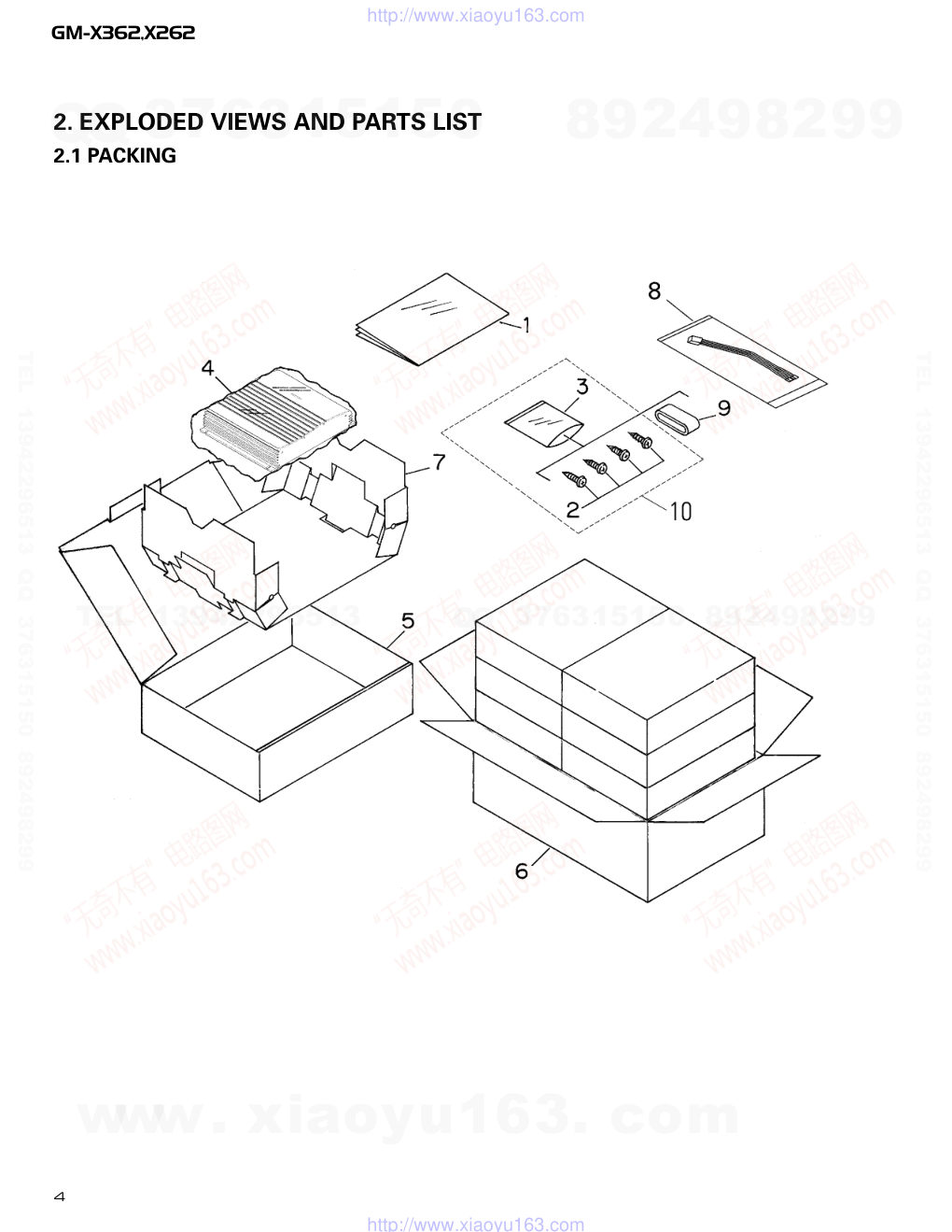
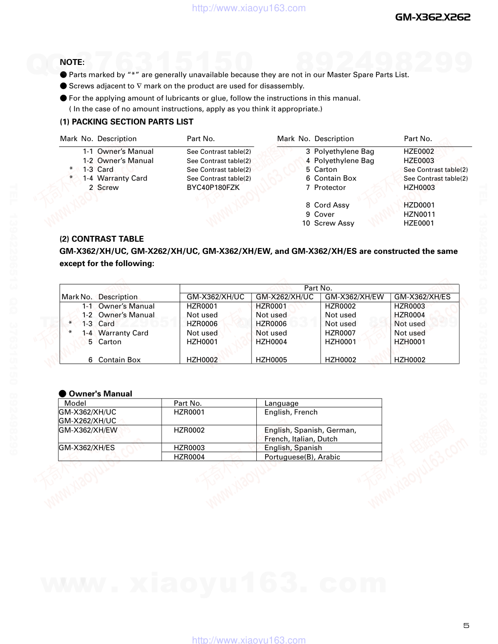
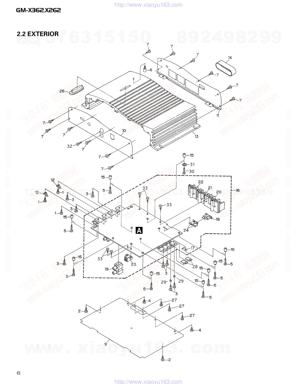
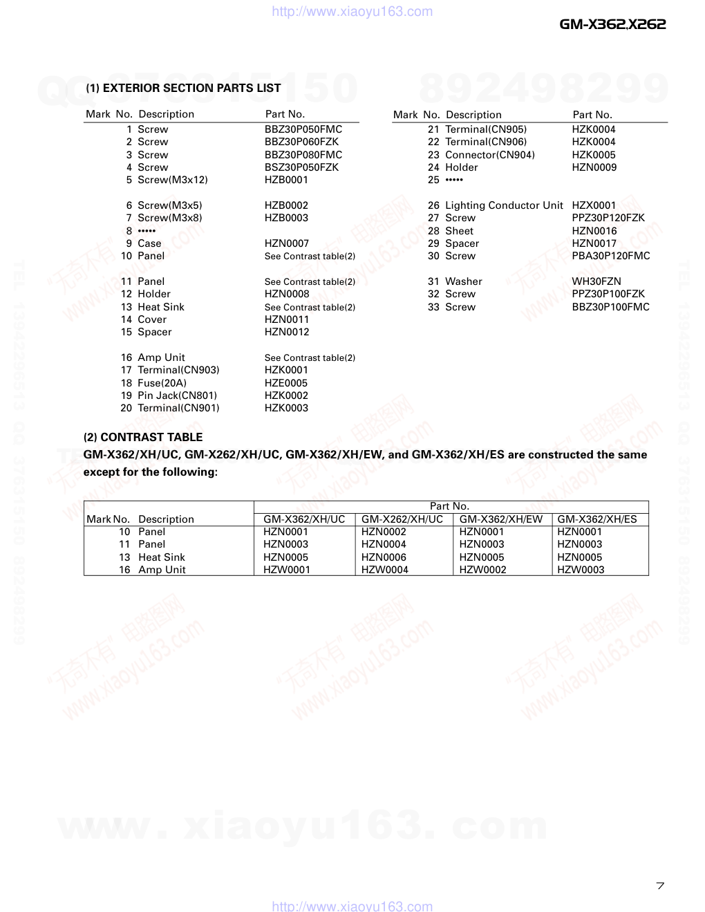
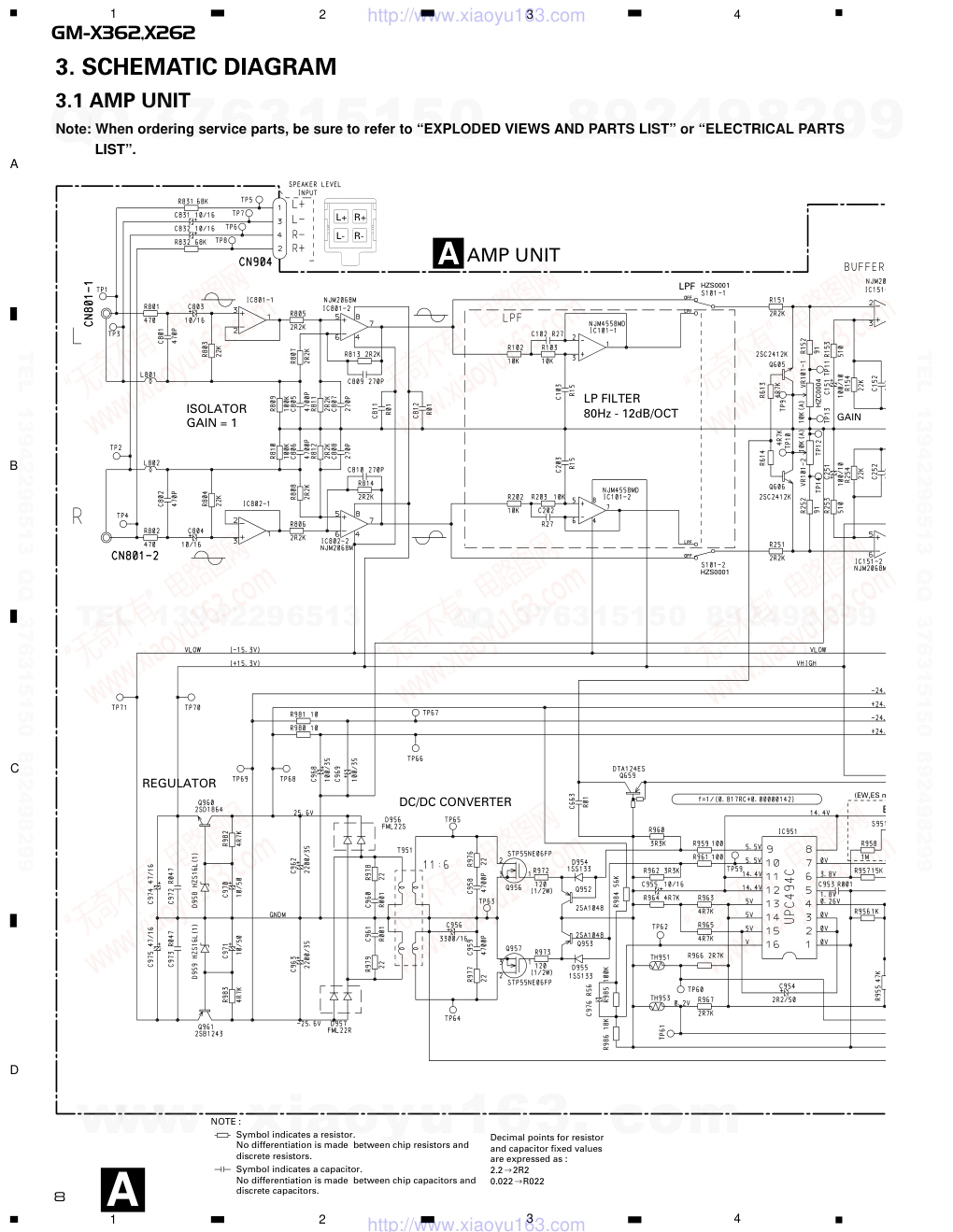
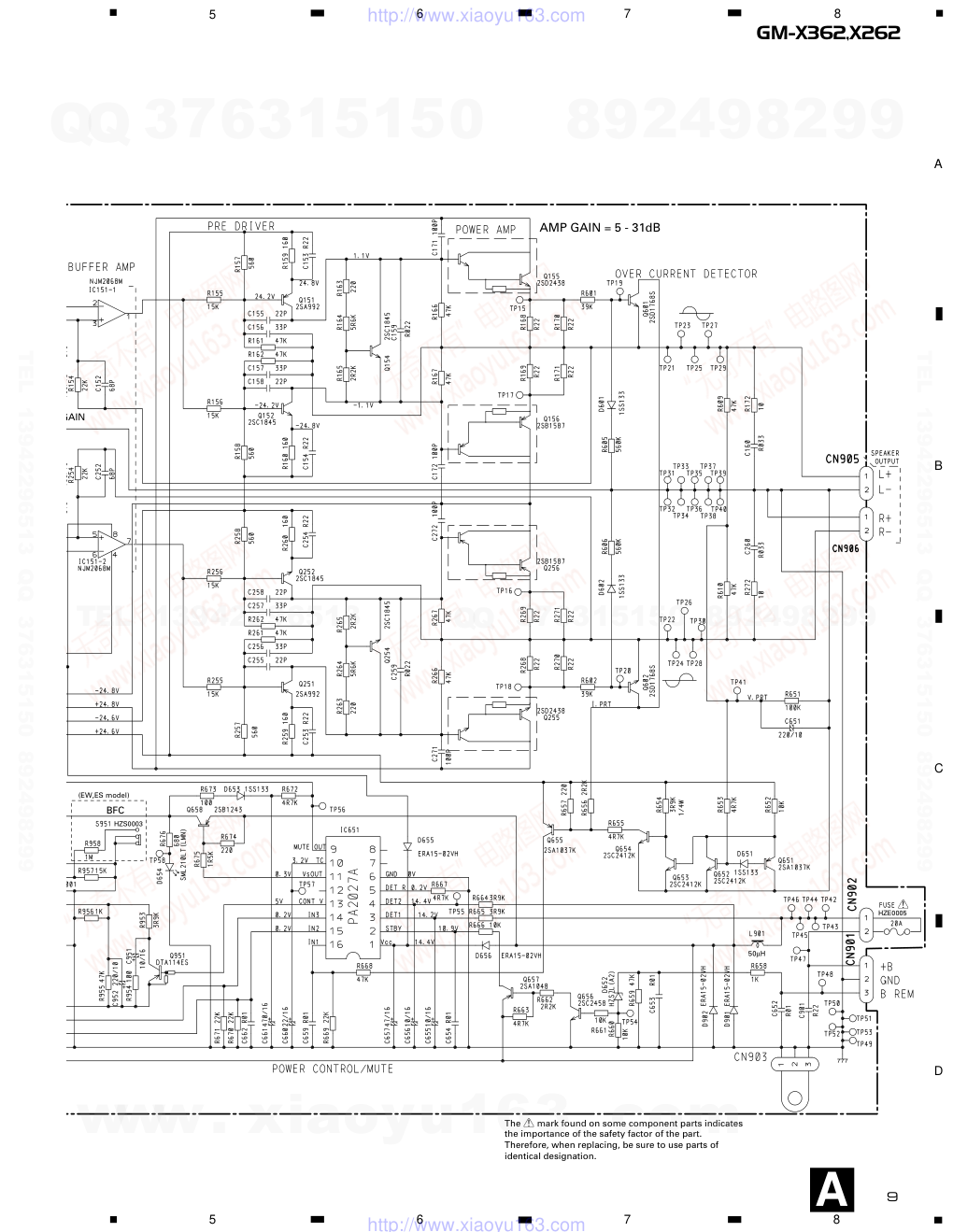
PIONEER CORPORATION 4-1, Meguro 1-Chome, Meguro-ku, Tokyo 153-8654, Japan PIONEER ELECTRONICS (USA) INC. P.O.Box 1760, Long Beach, CA 90801-1760 U.S.A. PIONEER EUROPE NV Haven 1087 Keetberglaan 1, 9120 Melsele, Belgium PIONEER ELECTRONICS ASIACENTRE PTE.LTD. 253 Alexandra Road, #04-01, Singapore 159936 C PIONEER CORPORATION 2001 K-ZZD. DEC. 2001 Printed in Japan ORDER NO. CRT2785 BRIDGEABLE POWER AMPLIFIER GM-X362 XH/UC,XH/EW,XH/ES Service Manual GM-X362/XH/UC CONTENTS 1. SAFETY INFORMATION............................................2 2. EXPLODED VIEWS AND PARTS LIST ......................4 3. SCHEMATIC DIAGRAM.............................................8 4. PCB CONNECTION DIAGRAM................................10 5. ELECTRICAL PARTS LIST........................................14 6. ADJUSTMENT.........................................................16 7. GENERAL INFORMATION.......................................17 7.1 DISASSEMBLY ..................................................17 8. OPERATIONS AND SPECIFICATIONS....................18 GM-X262 XH/UC For details, refer to "Important symbols for good services". www. xiaoyu163. com QQ 376315150 9 9 2 8 9 4 2 9 8 TEL 13942296513 9 9 2 8 9 4 2 9 8 0 5 1 5 1 3 6 7 3 Q Q TEL 13942296513 QQ 376315150 892498299 TEL 13942296513 QQ 376315150 892498299 http://www.xiaoyu163.com 2 GM-X362,X262 [ Important symbols for good services ] In this manual, the symbols shown-below indicate that adjustments, settings or cleaning should be made securely. When you find the procedures bearing any of the symbols, be sure to fulfill them: 2. Adjustments To keep the original performances of the product, optimum adjustments or specification confirmation is indispensable. In accordance with the procedures or instructions described in this manual, adjustments should be performed. 3. Cleaning For optical pickups, tape-deck heads, lenses and mirrors used in projection monitors, and other parts requiring cleaning, proper cleaning should be performed to restore their performances. 5. Lubricants, glues, and replacement parts Appropriately applying grease or glue can maintain the product performances. But improper lubrication or applying glue may lead to failures or troubles in the product. By following the instructions in this manual, be sure to apply the prescribed grease or glue to proper portions by the appropriate amount.For replacement parts or tools, the prescribed ones should be used. 4. Shipping mode and shipping screws To protect the product from damages or failures that may be caused during transit, the shipping mode should be set or the shipping screws should be installed before shipping out in accordance with this manual, if necessary. 1. Product safety You should conform to the regulations governing the product (safety, radio and noise, and other regulations), and should keep the safety during servicing by following the safety instructions described in this manual. 1. SAFETY INFORMATION - GM-X362/XH/UC, GM-X262/XH/UC CAUTION This service manual is intended for qualified service technicians; it is not meant for the casual do-it-yourselfer. Qualified technicians have the necessary test equipment and tools, and have been trained to properly and safely repair complex products such as those covered by this manual. Improperly performed repairs can adversely affect the safety and reliability of the product and may void the warranty. If you are not qualified to perform the repair of this product properly and safely, you should not risk trying to do so and refer the repair to a qualified service technician. WARNING This product contains lead in solder and certain electrical parts contain chemicals which are known to the state of California to cause cancer, birth defects or other reproductive harm. Health & Safety Code Section 25249.6 - Proposition 65 www. xiaoyu163. com QQ 376315150 9 9 2 8 9 4 2 9 8 TEL 13942296513 9 9 2 8 9 4 2 9 8 0 5 1 5 1 3 6 7 3 Q Q TEL 13942296513 QQ 376315150 892498299 TEL 13942296513 QQ 376315150 892498299 http://www.xiaoyu163.com 3 GM-X362,X262 www. xiaoyu163. com QQ 376315150 9 9 2 8 9 4 2 9 8 TEL 13942296513 9 9 2 8 9 4 2 9 8 0 5 1 5 1 3 6 7 3 Q Q TEL 13942296513 QQ 376315150 892498299 TEL 13942296513 QQ 376315150 892498299 http://www.xiaoyu163.com 4 GM-X362,X262 2. EXPLODED VIEWS AND PARTS LIST 2.1 PACKING www. xiaoyu163. com QQ 376315150 9 9 2 8 9 4 2 9 8 TEL 13942296513 9 9 2 8 9 4 2 9 8 0 5 1 5 1 3 6 7 3 Q Q TEL 13942296513 QQ 376315150 892498299 TEL 13942296513 QQ 376315150 892498299 http://www.xiaoyu163.com 5 GM-X362,X262 - Owner's Manual Model Part No. Language GM-X362/XH/UC HZR0001 English, French GM-X262/XH/UC GM-X362/XH/EW HZR0002 English, Spanish, German, French, Italian, Dutch GM-X362/XH/ES HZR0003 English, Spanish HZR0004 Portuguese(B), Arabic 1-1 Owner’s Manual See Contrast table(2) 1-2 Owner’s Manual See Contrast table(2) * 1-3 Card See Contrast table(2) * 1-4 Warranty Card See Contrast table(2) 2 Screw BYC40P180FZK 3 Polyethylene Bag HZE0002 4 Polyethylene Bag HZE0003 5 Carton See Contrast table(2) 6 Contain Box See Contrast table(2) 7 Protector HZH0003 8 Cord Assy HZD0001 9 Cover HZN0011 10 Screw Assy HZE0001 Mark No. Description Part No. Mark No. Description Part No. (1) PACKING SECTION PARTS LIST NOTE: - Parts marked by “*” are generally unavailable because they are not in our Master Spare Parts List. - Screws adjacent to ∇ mark on the product are used for disassembly. - For the applying amount of lubricants or glue, follow the instructions in this manual. ( In the case of no amount instructions, apply as you think it appropriate.) Part No. Mark No. Description GM-X362/XH/UC GM-X262/XH/UC GM-X362/XH/EW GM-X362/XH/ES 1-1 Owner’s Manual HZR0001 HZR0001 HZR0002 HZR0003 1-2 Owner’s Manual Not used Not used Not used HZR0004 * 1-3 Card HZR0006 HZR0006 Not used Not used * 1-4 Warranty Card Not used Not used HZR0007 Not used 5 Carton HZH0001 HZH0004 HZH0001 HZH0001 6 Contain Box HZH0002 HZH0005 HZH0002 HZH0002 (2) CONTRAST TABLE GM-X362/XH/UC, GM-X262/XH/UC, GM-X362/XH/EW, and GM-X362/XH/ES are constructed the same except for the following: www. xiaoyu163. com QQ 376315150 9 9 2 8 9 4 2 9 8 TEL 13942296513 9 9 2 8 9 4 2 9 8 0 5 1 5 1 3 6 7 3 Q Q TEL 13942296513 QQ 376315150 892498299 TEL 13942296513 QQ 376315150 892498299 http://www.xiaoyu163.com 6 GM-X362,X262 2.2 EXTERIOR A www. xiaoyu163. com QQ 376315150 9 9 2 8 9 4 2 9 8 TEL 13942296513 9 9 2 8 9 4 2 9 8 0 5 1 5 1 3 6 7 3 Q Q TEL 13942296513 QQ 376315150 892498299 TEL 13942296513 QQ 376315150 892498299 http://www.xiaoyu163.com 7 GM-X362,X262 (1) EXTERIOR SECTION PARTS LIST Mark No. Description Part No. Mark No. Description Part No. 1 Screw BBZ30P050FMC 2 Screw BBZ30P060FZK 3 Screw BBZ30P080FMC 4 Screw BSZ30P050FZK 5 Screw(M3x12) HZB0001 6 Screw(M3x5) HZB0002 7 Screw(M3x8) HZB0003 8 ••••• 9 Case HZN0007 10 Panel See Contrast table(2) 11 Panel See Contrast table(2) 12 Holder HZN0008 13 Heat Sink See Contrast table(2) 14 Cover HZN0011 15 Spacer HZN0012 16 Amp Unit See Contrast table(2) 17 Terminal(CN903) HZK0001 18 Fuse(20A) HZE0005 19 Pin Jack(CN801) HZK0002 20 Terminal(CN901) HZK0003 21 Terminal(CN905) HZK0004 22 Terminal(CN906) HZK0004 23 Connector(CN904) HZK0005 24 Holder HZN0009 25 ••••• 26 Lighting Conductor Unit HZX0001 27 Screw PPZ30P120FZK 28 Sheet HZN0016 29 Spacer HZN0017 30 Screw PBA30P120FMC 31 Washer WH30FZN 32 Screw PPZ30P100FZK 33 Screw BBZ30P100FMC Part No. Mark No. Description GM-X362/XH/UC GM-X262/XH/UC GM-X362/XH/EW GM-X362/XH/ES 10 Panel HZN0001 HZN0002 HZN0001 HZN0001 11 Panel HZN0003 HZN0004 HZN0003 HZN0003 13 Heat Sink HZN0005 HZN0006 HZN0005 HZN0005 16 Amp Unit HZW0001 HZW0004 HZW0002 HZW0003 (2) CONTRAST TABLE GM-X362/XH/UC, GM-X262/XH/UC, GM-X362/XH/EW, and GM-X362/XH/ES are constructed the same except for the following: www. xiaoyu163. com QQ 376315150 9 9 2 8 9 4 2 9 8 TEL 13942296513 9 9 2 8 9 4 2 9 8 0 5 1 5 1 3 6 7 3 Q Q TEL 13942296513 QQ 376315150 892498299 TEL 13942296513 QQ 376315150 892498299 http://www.xiaoyu163.com L+ R+ L- R- B LPF GAIN AMP UNIT LP FILTER 80Hz - 12dB/OCT ISOLATOR GAIN = 1 (EW,ES m REGULATOR DC/DC CONVERTER HZS0001 HZS0001 HZC0004 Decimal points for resistor and capacitor fixed values are expressed as : 2.2 2R2 0.022 R022 ← ← Symbol indicates a resistor. No differentiation is made between chip resistors and discrete resistors. NOTE : Symbol indicates a capacitor. No differentiation is made between chip capacitors and discrete capacitors. A 8 GM-X362,X262 A 1 2 3 4 B C D 1 2 3 4 3. SCHEMATIC DIAGRAM 3.1 AMP UNIT Note: When ordering service parts, be sure to refer to “EXPLODED VIEWS AND PARTS LIST” or “ELECTRICAL PARTS LIST”. A www. xiaoyu163. com QQ 376315150 9 9 2 8 9 4 2 9 8 TEL 13942296513 9 9 2 8 9 4 2 9 8 0 5 1 5 1 3 6 7 3 Q Q TEL 13942296513 QQ 376315150 892498299 TEL 13942296513 QQ 376315150 892498299 http://www.xiaoyu163.com BFC GAIN AMP GAIN = 5 - 31dB 50µH (EW,ES model) HZS0003 HZE0005 The > mark found on some component parts indicates the importance of the safety factor of the part. Therefore, when replacing, be sure to use parts of identical designation. > 9 GM-X362,X262 5 6 7 8 A B C D 5 6 7 8A www. xiaoyu163. com QQ 376315150 9 9 2 8 9 4 2 9 8 TEL 13942296513 9 9 2 8 9 4 2 9 8 0 5 1 5 1 3 6 7 3 Q Q TEL 13942296513 QQ 376315150 892498299 TEL 13942296513 QQ 376315150 892498299 http://www.xiaoyu163.com 10 GM-X362,X262 A 1 2 3 4 B C D 1 2 3 4 AMP UNIT 4. PCB CONNECTION DIAGRAM 4.1 AMP UNIT NOTE FOR PCB DIAGRAMS 1. The parts mounted on this PCB include all necessary parts for several destination. For further information for respective destinations, be sure to check with the schematic diagram. 2. Viewpoint of PCB diagrams Capacitor Connector P.C.Board Chip Part SIDE A SIDE B A FUSE SPEAKER INPUT A www. xiaoyu163. com QQ 376315150 9 9 2 8 9 4 2 9 8 TEL 13942296513 9 9 2 8 9 4 2 9 8 0 5 1 5 1 3 6 7 3 Q Q TEL 13942296513 QQ 376315150 892498299 TEL 13942296513 QQ 376315150 892498299 http://www.xiaoyu163.com 11 GM-X362,X262 5 6 7 8 A B C D 5 6 7 8 SPEAKER OUTPUT BFC LPF GAIN INPUT L R SIDE A A www. xiaoyu163. com QQ 376315150 9 9 2 8 9 4 2 9 8 TEL 13942296513 9 9 2 8 9 4 2 9 8 0 5 1 5 1 3 6 7 3 Q Q TEL 13942296513 QQ 376315150 892498299 TEL 13942296513 QQ 376315150 892498299 http://www.xiaoyu163.com 12 GM-X362,X262 A 1 2 3 4 B C D 1 2 3 4 A AMP UNIT A www. xiaoyu163. com QQ 376315150 9 9 2 8 9 4 2 9 8 TEL 13942296513 9 9 2 8 9 4 2 9 8 0 5 1 5 1 3 6 7 3 Q Q TEL 13942296513 QQ 376315150 892498299 TEL 13942296513 QQ 376315150 892498299 http://www.xiaoyu163.com 13 GM-X362,X262 5 6 7 8 A B C D 5 6 7 8 SIDE B A www. xiaoyu163. com QQ 376315150 9 9 2 8 9 4 2 9 8 TEL 13942296513 9 9 2 8 9 4 2 9 8 0 5 1 5 1 3 6 7 3 Q Q TEL 13942296513 QQ 376315150 892498299 TEL 13942296513 QQ 376315150 892498299 http://www.xiaoyu163.com 14 GM-X362,X262 D 902 Diode ERA15-02VH D 954 Diode 1SS133 D 955 Diode 1SS133 D 956 Diode FML22S D 957 Diode FML22R D 958 Diode HZS16L(1) D 959 Diode HZS16L(1) L 801 Inductor HZT0001 L 802 Inductor HZT0001 L 901 Choke Coil 50µH HZT0002 T 951 Transformer HZT0003 TH 951 Thermistor HZC0005 TH 953 Thermistor HZC0006 S 101 Switch(LPF SELECT) HZS0001 S 951 Switch(BFC)(EW,ES model) HZS0003 VR 101 Volume 10kΩ(A) HZC0004 Fuse 20A HZE0005 RESISTORS R 102 RS1/10S103J R 103 RS1/10S103J R 151 RS1/10S222J R 152 RS1/10S910J R 153 RS1/10S511J R 154 RS1/10S223J R 155 RS1/10S153J R 156 RS1/10S153J R 157 RD1/4PU561J R 158 RD1/4PU561J R 159 RD1/4PU161J R 160 RD1/4PU161J R 161 RD1/4PU473J R 162 RD1/4PU473J R 163 RD1/4PU221J R 164 RD1/4PU562J R 165 RD1/4PU222J R 166 RD1/4PU473J R 167 RD1/4PU473J R 168 0.22Ω HZC0003 R 169 0.22Ω HZC0003 R 170 0.22Ω HZC0003 R 171 0.22Ω HZC0003 R 172 RD1/2PM100J R 202 RS1/10S103J R 203 RS1/10S103J R 251 RS1/10S222J R 252 RS1/10S910J R 253 RS1/10S511J R 254 RS1/10S223J R 255 RS1/10S153J R 256 RS1/10S153J R 257 RD1/4PU561J R 258 RD1/4PU561J R 259 RD1/4PU161J 5. ELECTRICAL PARTS LIST NOTE: - Parts whose parts numbers are omitted are subject to being not supplied. - The part numbers shown below indicate chip components. Chip Resistor RS1/_S___J,RS1/__S___J Chip Capacitor (except for CQS.....) CKS....., CCS....., CSZS..... Unit Number : HZW0001(GM-X362/XH/UC) Unit Number : HZW0002(GM-X362/XH/EW) Unit Number : HZW0003(GM-X362/XH/ES) Unit Number : HZW0004(GM-X262/XH/UC) Unit Name : Amp Unit MISCELLANEOUS IC 101 IC NJM4558MD IC 151 IC NJM2068M IC 651 IC PA2027A IC 801 IC NJM2068M IC 802 IC NJM2068M IC 951 IC UPC494C Q 151 Transistor 2SA992 Q 152 Transistor 2SC1845 Q 154 Transistor 2SC1845 Q 155 Transistor 2SD2438 Q 156 Transistor 2SB1587 Q 251 Transistor 2SA992 Q 252 Transistor 2SC1845 Q 254 Transistor 2SC1845 Q 255 Transistor 2SD2438 Q 256 Transistor 2SB1587 Q 601 Transistor 2SD1768S Q 602 Transistor 2SD1768S Q 605 Transistor 2SC2412K Q 606 Transistor 2SC2412K Q 651 Transistor 2SA1037K Q 652 Transistor 2SC2412K Q 653 Transistor 2SC2412K Q 654 Transistor 2SC2412K Q 655 Transistor 2SA1037K Q 656 Transistor 2SC2458 Q 657 Transistor 2SA1048 Q 658 Transistor 2SB1243 Q 659 Transistor DTA124ES Q 951 Transistor DTA114ES Q 952 Transistor 2SA1048 Q 953 Transistor 2SA1048 Q 956 FET STP55NE06FP Q 957 FET STP55NE06FP Q 960 Transistor 2SD1864 Q 961 Transistor 2SB1243 D 601 Diode 1SS133 D 602 Diode 1SS133 D 651 Diode 1SS133 D 652 Diode HZS7L(A2) D 653 Diode 1SS133 D 654 LED SML210LT(LMN) D 655 Diode ERA15-02VH D 656 Diode ERA15-02VH D 901 Diode ERA15-02VH =====Circuit Symbol and No.===Part Name Part No. --- ------ ------------------------------------------ ------------------------- =====Circuit Symbol and No.===Part Name Part No. --- ------ ------------------------------------------ ------------------------- A www. xiaoyu163. com QQ 376315150 9 9 2 8 9 4 2 9 8 TEL 13942296513 9 9 2 8 9 4 2 9 8 0 5 1 5 1 3 6 7 3 Q Q TEL 13942296513 QQ 376315150 892498299 TEL 13942296513 QQ 376315150 892498299 http://www.xiaoyu163.com 15 GM-X362,X262 R 260 RD1/4PU161J R 261 RD1/4PU473J R 262 RD1/4PU473J R 263 RD1/4PU221J R 264 RD1/4PU562J R 265 RD1/4PU222J R 266 RD1/4PU473J R 267 RD1/4PU473J R 268 0.22Ω HZC0003 R 269 0.22Ω HZC0003 R 270 0.22Ω HZC0003 R 271 0.22Ω HZC0003 R 272 RD1/2PM100J R 601 RD1/4PU393J R 602 RD1/4PU393J R 605 RD1/4PU564J R 606 RD1/4PU564J R 609 RD1/2PM473J R 610 RD1/2PM473J R 613 RS1/10S472J R 614 RS1/10S472J R 651 RS1/10S104J R 652 RS1/10S103J R 653 RS1/10S472J R 654 RD1/4PU392J R 655 RS1/10S472J R 656 RS1/10S222J R 657 RS1/10S221J R 658 RS1/10S102J R 659 RS1/10S473J R 660 RS1/10S103J R 661 RS1/10S103J R 662 RS1/10S222J R 663 RS1/10S472J R 664 RS1/10S392J R 665 RS1/10S392J R 666 RS1/10S103J R 667 RS1/10S472J R 668 RS1/10S473J R 669 RS1/10S223J R 670 RS1/10S223J R 671 RS1/10S223J R 672 RS1/10S472J R 673 RD1/4PU101J R 674 RD1/4PU221J R 675 RD1/4PU152J R 676 RD1/2PM681J R 801 RS1/10S471J R 802 RS1/10S471J R 803 RS1/10S223J R 804 RS1/10S223J R 805 RN1/10SE2201D R 806 RN1/10SE2201D R 807 RN1/10SE2201D R 808 RN1/10SE2201D R 809 RS1/10S104J R 810 RS1/10S104J R 811 RN1/10SE2201D R 812 RN1/10SE2201D R 813 RN1/10SE2201D R 814 RN1/10SE2201D R 831 RS1/10S683J R 832 RS1/10S683J R 953 RD1/4PU392J R 954 RD1/4PU101J R 955 RS1/10S473J R 956 RS1/10S102J R 957 RS1/10S153J R 958 (EW,ES model) RS1/10S105J R 959 RD1/4PU101J R 960 RD1/4PU332J R 961 RD1/4PU101J R 962 RS1/10S332J R 963 RS1/10S472J R 964 RS1/10S472J R 965 RS1/10S472J R 966 RD1/4PU272J R 967 RD1/4PU272J R 972 RD1/2PM121J R 973 RD1/2PM121J R 976 RD1/2PM220J R 977 RD1/2PM220J R 978 RD1/2PM220J R 979 RD1/2PM220J R 980 RD1/4PU100J R 981 RD1/4PU100J R 982 RD1/4PU472J R 983 RD1/4PU472J R 984 RD1/4PU563J R 985 RD1/4PU104J R 986 RD1/4PU183J CAPACITORS C 102 CKSQYB274K16 C 103 CKSQYB154K16 C 151 CEAS101M10 C 152 CCSQSL680J50 C 153 CFTNA224J50 C 154 CFTNA224J50 C 155 CCSQCH220J50 C 156 CCCCH330J100 C 157 CCCCH330J100 C 158 CCSQCH220J50 C 159 CFTLA223J50 C 160 CFTLA333J50 C 171 CCSQCH101J50 C 172 CCSQCH101J50 C 202 CKSQYB274K16 C 203 CKSQYB154K16 C 251 CEAS101M10 C 252 CCSQSL680J50 C 253 CFTNA224J50 C 254 CFTNA224J50 C 255 CCSQCH220J50 C 256 CCCCH330J100 C 257 CCCCH330J100 C 258 CCSQCH220J50 C 259 CFTLA223J50 C 260 CFTLA333J50 C 271 CCSQCH101J50 C 272 CCSQCH101J50 C 651 220µF/10V HZC0001 C 652 CKSQYB103K50 C 653 CKSQYB103K50 C 654 CKSQYB103K50 C 655 CEAS100M16 C 656 CEAS100M16 C 657 CEAS470M16 C 659 CKSQYB103K50 C 660 CEAS220M16 C 661 470µF/16V HZC0002 C 662 CKSQYB103K50 C 663 CQMA103J50 =====Circuit Symbol and No.===Part Name Part No. --- ------ ------------------------------------------ ------------------------- =====Circuit Symbol and No.===Part Name Part No. --- ------ ------------------------------------------ ------------------------- www. xiaoyu163. com QQ 376315150 9 9 2 8 9 4 2 9 8 TEL 13942296513 9 9 2 8 9 4 2 9 8 0 5 1 5 1 3 6 7 3 Q Q TEL 13942296513 QQ 376315150 892498299 TEL 13942296513 QQ 376315150 892498299 http://www.xiaoyu163.com 16 GM-X362,X262 C 801 CKSQYB471K50 C 802 CKSQYB471K50 C 803 CEAS100M16 C 804 CEAS100M16 C 805 CKSQYB472K50 C 806 CKSQYB472K50 C 807 CCSQCH271J50 C 808 CCSQCH271J50 C 809 CCSQCH271J50 C 810 CCSQCH271J50 C 811 CKSQYB103K50 C 812 CKSQYB103K50 C 831 CEAS100M16 C 832 CEAS100M16 C 901 CFTNA224J50 C 951 CEAS100M16 C 952 CEAS221M10 C 953 CQMA102J50 C 954 CEAS2R2M50 C 955 CEAS100M16 C 956 3300µF/16V HZC0008 C 958 CQMA472J50 C 959 CQMA472J50 C 960 CQMA102J50 C 961 CQMA102J50 C 962 2200µF/35V HZC0007 C 963 2200µF/35V HZC0007 C 968 CEAS101M35 C 969 CEAS101M35 C 970 CEAS100M50 C 971 CEAS100M50 C 972 CKSQYB473K50 C 973 CKSQYB473K50 C 974 CEAS470M16 C 975 CEAS470M16 C 976 CFTNA564J50 =====Circuit Symbol and No.===Part Name Part No. --- ------ ------------------------------------------ ------------------------- =====Circuit Symbol and No.===Part Name Part No. --- ------ ------------------------------------------ ------------------------- 6. ADJUSTMENT There is no information to be shown in this chapter. www. xiaoyu163. com QQ 376315150 9 9 2 8 9 4 2 9 8 TEL 13942296513 9 9 2 8 9 4 2 9 8 0 5 1 5 1 3 6 7 3 Q Q TEL 13942296513 QQ 376315150 892498299 TEL 13942296513 QQ 376315150 892498299 http://www.xiaoyu163.com GM-X362,X262 17 7. GENERAL INFORMATION 7.1 DISASSEMBLY Case Fig.1 - Removing the Case and the Panel (Fig.1) Remove the three screws. Remove the two screws. Remove the two screws and then remove the Case. Remove the six screws and then remove the Panel. Fig.2 Panel - Removing the Amp Unit (Fig.2) Remove the eleven screws. Remove the screw. Remove the nine screws and then remove the Amp Unit. Amp Unit www. xiaoyu163. com QQ 376315150 9 9 2 8 9 4 2 9 8 TEL 13942296513 9 9 2 8 9 4 2 9 8 0 5 1 5 1 3 6 7 3 Q Q TEL 13942296513 QQ 376315150 892498299 TEL 13942296513 QQ 376315150 892498299 http://www.xiaoyu163.com 18 GM-X362,X262 8. OPERATIONS AND SPECIFICATIONS 8.1 OPERATIONS - GM-X362/XH/EW www. xiaoyu163. com QQ 376315150 9 9 2 8 9 4 2 9 8 TEL 13942296513 9 9 2 8 9 4 2 9 8 0 5 1 5 1 3 6 7 3 Q Q TEL 13942296513 QQ 376315150 892498299 TEL 13942296513 QQ 376315150 892498299 http://www.xiaoyu163.com 19 GM-X362,X262 LPF (Low-Pass Filter) Select Switch Set the LPF select switch as follows according to the type of speaker that is connected to the speaker output connector and the car stereo system: LPF Select Audio frequency range Speaker Remarks Switch to be output Type LPF (left) Very Low Frequency range Subwoofer Connect a subwoofer. OFF (right) Full range Full range Gain Control If the sound level is too low, even when the volume of the car stereo used along with this power amplifier is turned up, turn gain control on the front of the power amplifier clockwise. If the sound distorts when the volume is turned up, turn the gain control counter-clockwise. • When using with an RCA equipped car stereo (standard output of 500 mV), set to the NORMAL position. When using with an RCA equipped Pioneer car stereo with max. output of 4 V or more, adjust level to match the car stereo output level. • If you hear too much noise when using the speaker input terminals, turn the gain control counter-clockwise. Power Indicator The power indicator lights when the power is switched on. BFC (Beat Frequency Control) Switch If you hear a beat while listening to an MW/LW broadcast with your car stereo, change the BFC switch using a small standard tip screwdriver. www. xiaoyu163. com QQ 376315150 9 9 2 8 9 4 2 9 8 TEL 13942296513 9 9 2 8 9 4 2 9 8 0 5 1 5 1 3 6 7 3 Q Q TEL 13942296513 QQ 376315150 892498299 TEL 13942296513 QQ 376315150 892498299 http://www.xiaoyu163.com 20 GM-X362,X262 Connection Diagram Fuse (30 A) Grommet Special red battery wire [RD-223] (sold separately) After making all other connections at the amplifier, connect the battery wire terminal of the amplifier to the positive (+) terminal of the battery. Ground wire (black) [RD-223] (sold separately) Connect to metal body or chassis. Fuse (20 A) Car stereo with RCA output jacks External Output Connecting wires with RCA pin plugs (sold separately). RCA input jack System remote control wire (sold separately) Connect the male terminal of this wire to the system remote control terminal of the car stereo (SYSTEM REMOTE CONTROL). The female terminal can be connected to the auto-antenna relay control terminal. If the car stereo does not have a system remote control terminal, connect the male terminal to the power terminal through the ignition switch. Speaker output terminal See the “Connecting the Speaker wires” section for speaker connection instructions. Fuse (30 A) Front side Back side Speaker input terminal See the “Using the Speaker Input” section. www. xiaoyu163. com QQ 376315150 9 9 2 8 9 4 2 9 8 TEL 13942296513 9 9 2 8 9 4 2 9 8 0 5 1 5 1 3 6 7 3 Q Q TEL 13942296513 QQ 376315150 892498299 TEL 13942296513 QQ 376315150 892498299 http://www.xiaoyu163.com 21 GM-X362,X262 8.2 SPECIFICATIONS - GM-X362/XH/UC Power source .............................................................................................................. 14.4 V DC (10.8 — 15.1 V allowable) Grounding system ............................................................................................................................................ Negative type Current consumption ........................................................................................................ 11.3 A (at continuous power, 4 Ω) Average current drawn* ............................................................................................................ 3.8 A (4 Ω for two channels) 5.9 A (4 Ω for one channel) Fuse .................................................................................................................................................................................. 20 A Dimensions .......................................................................................................................... 279 (W) × 61 (H) × 157 (D) mm [11 (W) × 2-3/8 (H) × 6-1/8 (D) in] Weight .......................................................................................................... 2.6 kg (5.7 lbs) (Leads for wiring not included) Maximum power output ...................................................................................................................... 80 W × 2 / 200 W × 1 Continuous power output ............................................................ 40 W × 2 (at 14.4 V, 4 Ω, 20 — 20,000 Hz, 0.08% THD) 100 W × 1 (at 14.4 V, 4 Ω, 20 — 20,000 Hz, 0.8% THD) 50 W × 2 (at 14.4 V, 2 Ω, 20 — 20,000 Hz, 0.8% THD) Load impedance .............................................................................................................................. 4 Ω (2 — 8 Ω allowable) (Bridge connection: 4 — 8 Ω allowable) Frequency response ............................................................................................................ 10 — 50,000 Hz (+0 dB, –1 dB) Signal-to-noise ratio ...................................................................................................................... 100 dB (IHF–A network) Distortion ............................................................................................................................................ 0.008% (10 W, 1 kHz) Separation ........................................................................................................................................................ 60 dB (1 kHz) Low pass filter ................................................................................................................................ Cut off frequency: 80 Hz Cut off slope: –12 dB/oct Maximum input level/impedance .................................................................................... RCA: 6.5 V/22 kΩ (0.4 — 6.5 V) Speaker: 26 V/40 kΩ (1.6 — 26 V) Note: • Specifications and the design are subject to possible modification without notice due to improvements. *Average current drawn • The average current drawn is nearly the maximum current drawn by this unit when an audio signal is input. Use this value when working out total current drawn by multiple power amplifiers. - GM-X262/XH/UC Power source .............................................................................................................. 14.4 V DC (10.8 — 15.1 V allowable) Grounding system ............................................................................................................................................ Negative type Current consumption ........................................................................................................ 11.3 A (at continuous power, 4 Ω) Average current drawn* ............................................................................................................ 3.8 A (4 Ω for two channels) 5.9 A (4 Ω for one channel) Fuse .................................................................................................................................................................................. 20 A Dimensions .......................................................................................................................... 279 (W) × 61 (H) × 157 (D) mm [11 (W) × 2-3/8 (H) × 6-1/8 (D) in] Weight .......................................................................................................... 2.6 kg (5.7 lbs) (Leads for wiring not included) Maximum power output ...................................................................................................................... 80 W × 2 / 200 W × 1 Continuous power output ............................................................ 40 W × 2 (at 14.4 V, 4 Ω, 20 — 20,000 Hz, 0.08% THD) 100 W × 1 (at 14.4 V, 4 Ω, 20 — 20,000 Hz, 0.8% THD) 50 W × 2 (at 14.4 V, 2 Ω, 20 — 20,000 Hz, 0.8% THD) Load impedance .............................................................................................................................. 4 Ω (2 — 8 Ω allowable) (Bridge connection: 4 — 8 Ω allowable) Frequency response ............................................................................................................ 10 — 50,000 Hz (+0 dB, –1 dB) Signal-to-noise ratio ...................................................................................................................... 100 dB (IHF–A network) Distortion ............................................................................................................................................ 0.008% (10 W, 1 kHz) Separation ........................................................................................................................................................ 60 dB (1 kHz) Low pass filter ................................................................................................................................ Cut off frequency: 80 Hz Cut off slope: –12 dB/oct Maximum input level/impedance .................................................................................... RCA: 6.5 V/22 kΩ (0.4 — 6.5 V) Speaker: 26 V/40 kΩ (1.6 — 26 V) Note: • Specifications and the design are subject to possible modification without notice due to improvements. *Average current drawn • The average current drawn is nearly the maximum current drawn by this unit when an audio signal is input. Use this value when working out total current drawn by multiple power amplifiers. www. xiaoyu163. com QQ 376315150 9 9 2 8 9 4 2 9 8 TEL 13942296513 9 9 2 8 9 4 2 9 8 0 5 1 5 1 3 6 7 3 Q Q TEL 13942296513 QQ 376315150 892498299 TEL 13942296513 QQ 376315150 892498299 http://www.xiaoyu163.com GM-X362,X262 - GM-X362/XH/ES Power source .............................................................................................................. 14.4 V DC (10.8 — 15.1 V allowable) Grounding system ............................................................................................................................................ Negative type Current consumption ........................................................................................................ 11.3 A (at continuous power, 4 Ω) Average current drawn* ............................................................................................................ 3.8 A (4 Ω for two channels) 5.9 A (4 Ω for one channel) Fuse .................................................................................................................................................................................. 20 A Dimensions .......................................................................................................................... 279 (W) × 61 (H) × 157 (D) mm Weight ........................................................................................................................ 2.6 kg (Leads for wiring not included) Maximum power output ...................................................................................................................... 80 W × 2 / 200 W × 1 Continuous power output ............................................................ 40 W × 2 (at 14.4 V, 4 Ω, 20 — 20,000 Hz, 0.08% THD) 100 W × 1 (at 14.4 V, 4 Ω, 20 — 20,000 Hz, 0.8% THD) 50 W × 2 (at 14.4 V, 2 Ω, 20 — 20,000 Hz, 0.8% THD) Load impedance .............................................................................................................................. 4 Ω (2 — 8 Ω allowable) (Bridge connection: 4 — 8 Ω allowable) Frequency response ............................................................................................................ 10 — 50,000 Hz (+0 dB, –1 dB) Signal-to-noise ratio ........................................................................................................................ 100 dB (IEC-A network) Distortion ............................................................................................................................................ 0.008% (10 W, 1 kHz) Separation ........................................................................................................................................................ 60 dB (1 kHz) Low pass filter ................................................................................................................................ Cut off frequency: 80 Hz Cut off slope: –12 dB/oct Maximum input level/impedance .................................................................................... RCA: 6.5 V/22 kΩ (0.4 — 6.5 V) Speaker: 26 V/40 kΩ (1.6 — 26 V) Note: • Specifications and the design are subject to possible modification without notice due to improvements. *Average current drawn • The average current drawn is nearly the maximum current drawn by this unit when an audio signal is input. Use this value when working out total current drawn by multiple power amplifiers. - GM-X362/XH/EW Power source .......................................................................................................... 14.4 V DC (10.8 — 15.1 V allowable) Grounding system .......................................................................................................................................... Negative type Current consumption .................................................................................................... 11.3 A (at continuous power, 4 Ω) Average current drawn* ........................................................................................................ 3.8 A (4 Ω for two channels) 5.9 A (4 Ω for one channel) Fuse .............................................................................................................................................................................. 20 A Dimensions ...................................................................................................................... 279 (W) × 61 (H) × 157 (D) mm Weight .................................................................................................................... 2.6 kg (Leads for wiring not included) Maximum power output .................................................................................................................... 80 W × 2 / 200 W × 1 Continuous power output ........................................................................ 60 W × 2 / 150 W × 1 (DIN45324, +B=14.4 V) Load impedance .......................................................................................................................... 4 Ω (2 — 8 Ω allowable) (Bridge connection: 4 — 8 Ω allowable) Frequency response .......................................................................................................... 10 — 50,000 Hz (+0 dB, –1 dB) Signal-to-noise ratio .................................................................................................................... 100 dB (IEC-A network) Distortion ........................................................................................................................................ 0.008 % (10 W, 1 kHz) Separation ...................................................................................................................................................... 60 dB (1 kHz) Low pass filter .............................................................................................................................. Cut off frequency: 80 Hz Cut off slope: –12 dB/oct Maximum input level/impedance .................................................................................. RCA: 6.5 V/22 kΩ (0.4 — 6.5 V) Speaker: 26 V/40 kΩ (1.6 — 26 V) Note: • Specifications and the design are subject to possible modification without notice due to improvements. *Average current drawn • The average current drawn is nearly the maximum current drawn by this unit when an audio signal is input. Use this value when working out total current drawn by multiple power amplifiers. www. xiaoyu163. com QQ 376315150 9 9 2 8 9 4 2 9 8 TEL 13942296513 9 9 2 8 9 4 2 9 8 0 5 1 5 1 3 6 7 3 Q Q TEL 13942296513 QQ 376315150 892498299 TEL 13942296513 QQ 376315150 892498299 http://www.xiaoyu163.com
版权声明
1. 本站所有素材,仅限学习交流,仅展示部分内容,如需查看完整内容,请下载原文件。
2. 会员在本站下载的所有素材,只拥有使用权,著作权归原作者所有。
3. 所有素材,未经合法授权,请勿用于商业用途,会员不得以任何形式发布、传播、复制、转售该素材,否则一律封号处理。
4. 如果素材损害你的权益请联系客服QQ:77594475 处理。