先锋PIONEER F-X88ZL音响电路图
 "先锋PIONEER F-X88ZL音响电路图-0")
 "先锋PIONEER F-X88ZL音响电路图-1")
 "先锋PIONEER F-X88ZL音响电路图-2")
 "先锋PIONEER F-X88ZL音响电路图-3")
 "先锋PIONEER F-X88ZL音响电路图-4")
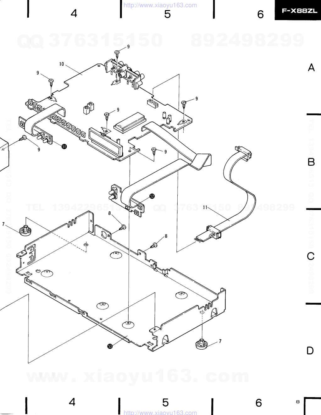
 "先锋PIONEER F-X88ZL音响电路图-5")
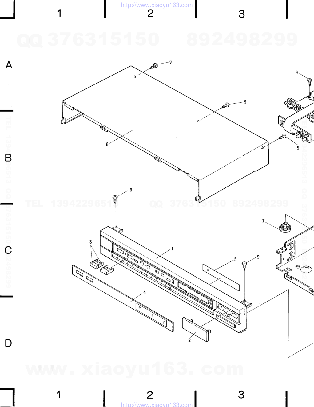 "先锋PIONEER F-X88ZL音响电路图-6")
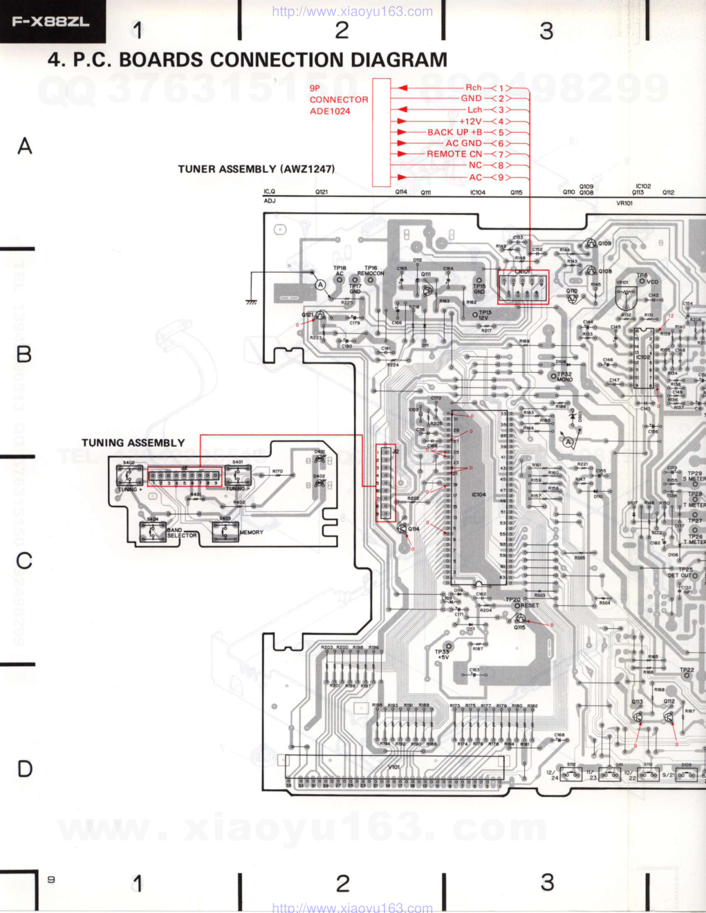
 "先锋PIONEER F-X88ZL音响电路图-7")
 "先锋PIONEER F-X88ZL音响电路图-8")
 "先锋PIONEER F-X88ZL音响电路图-9")
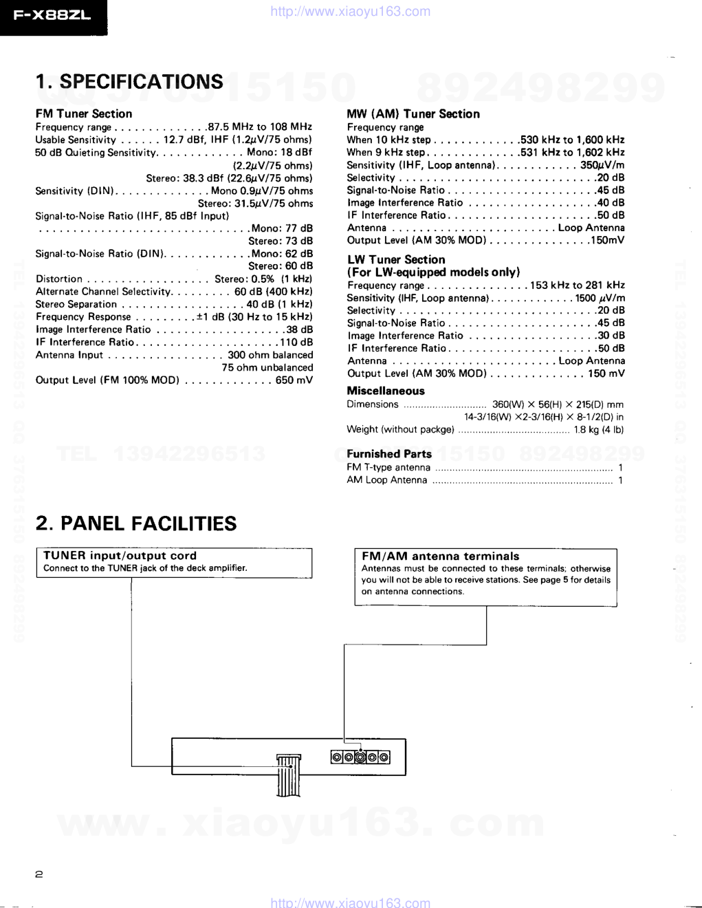
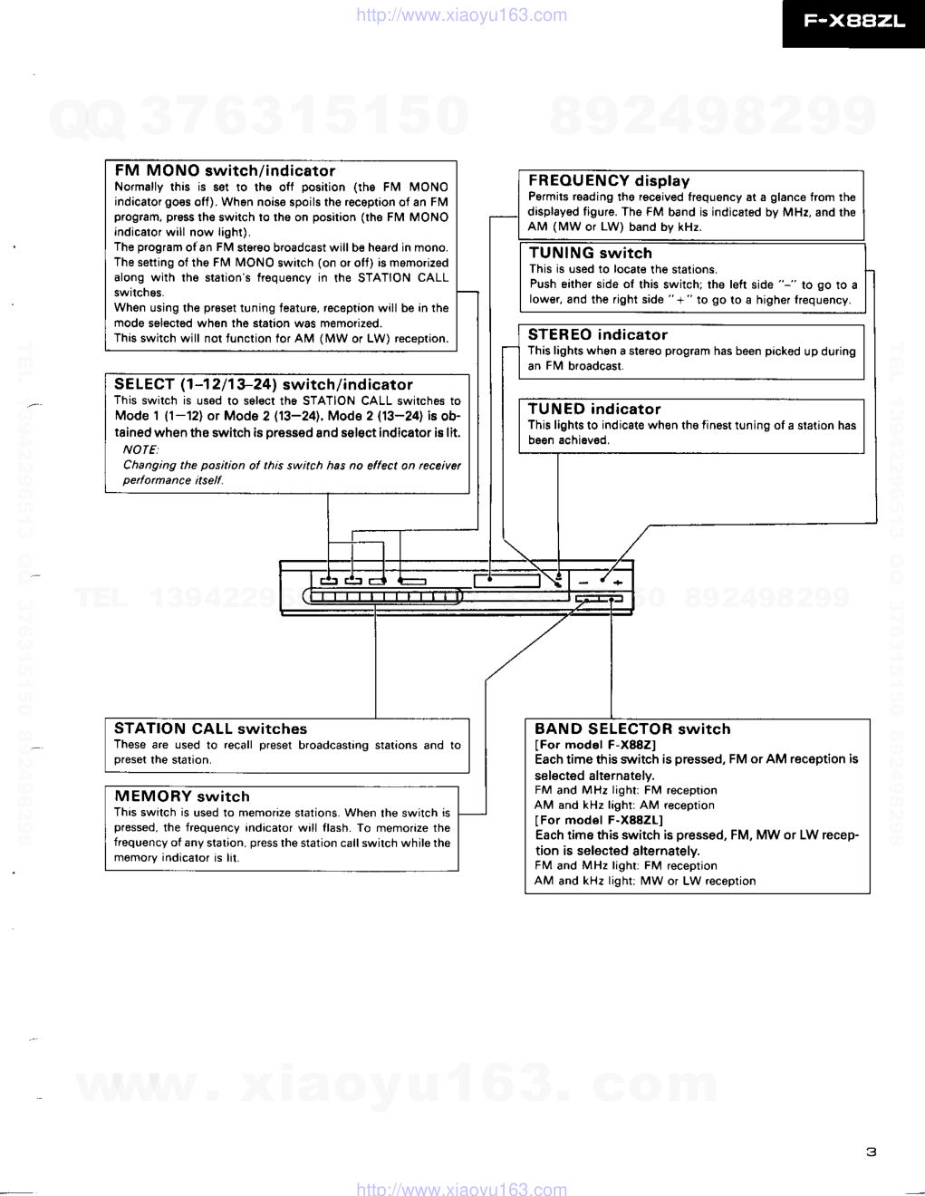
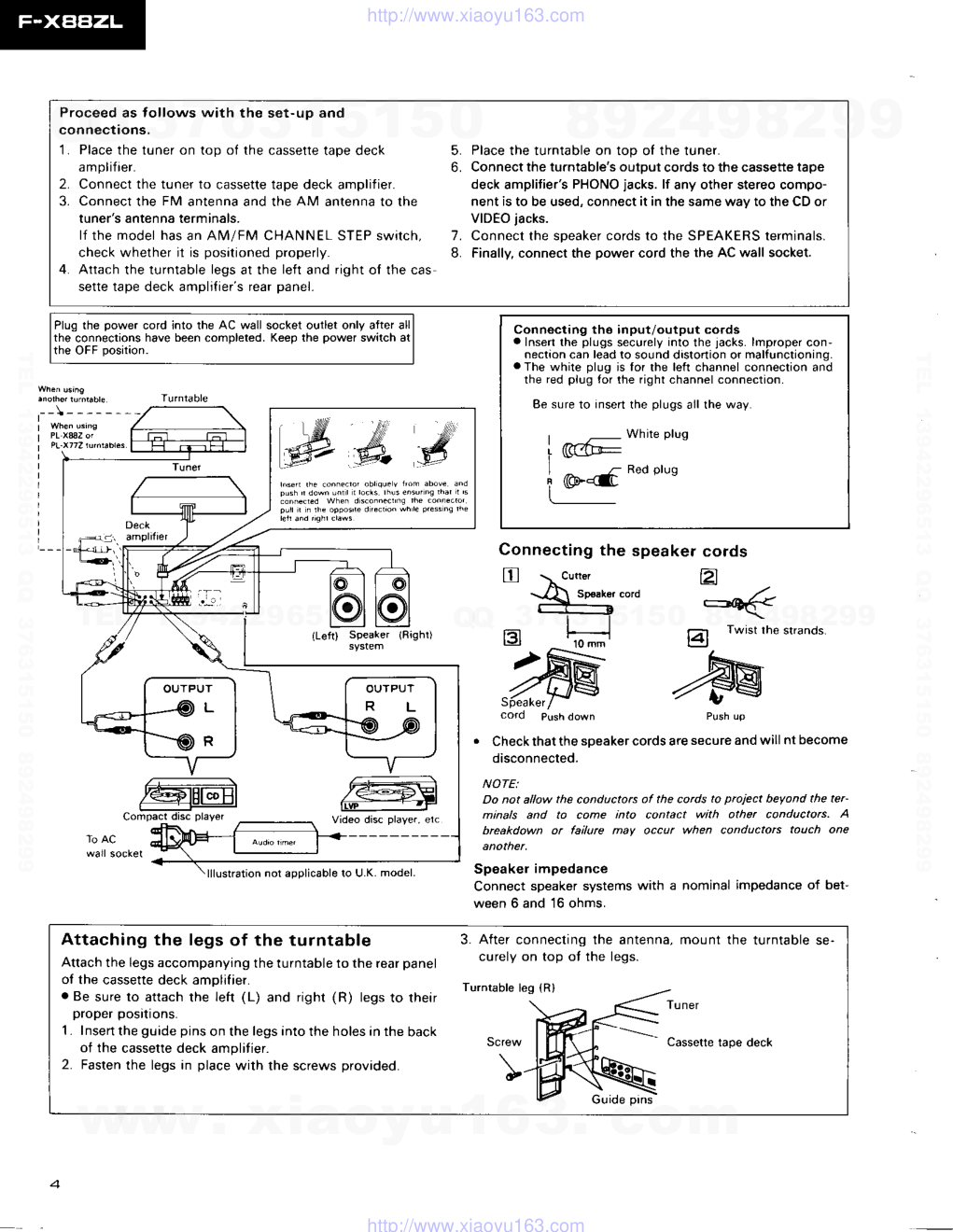
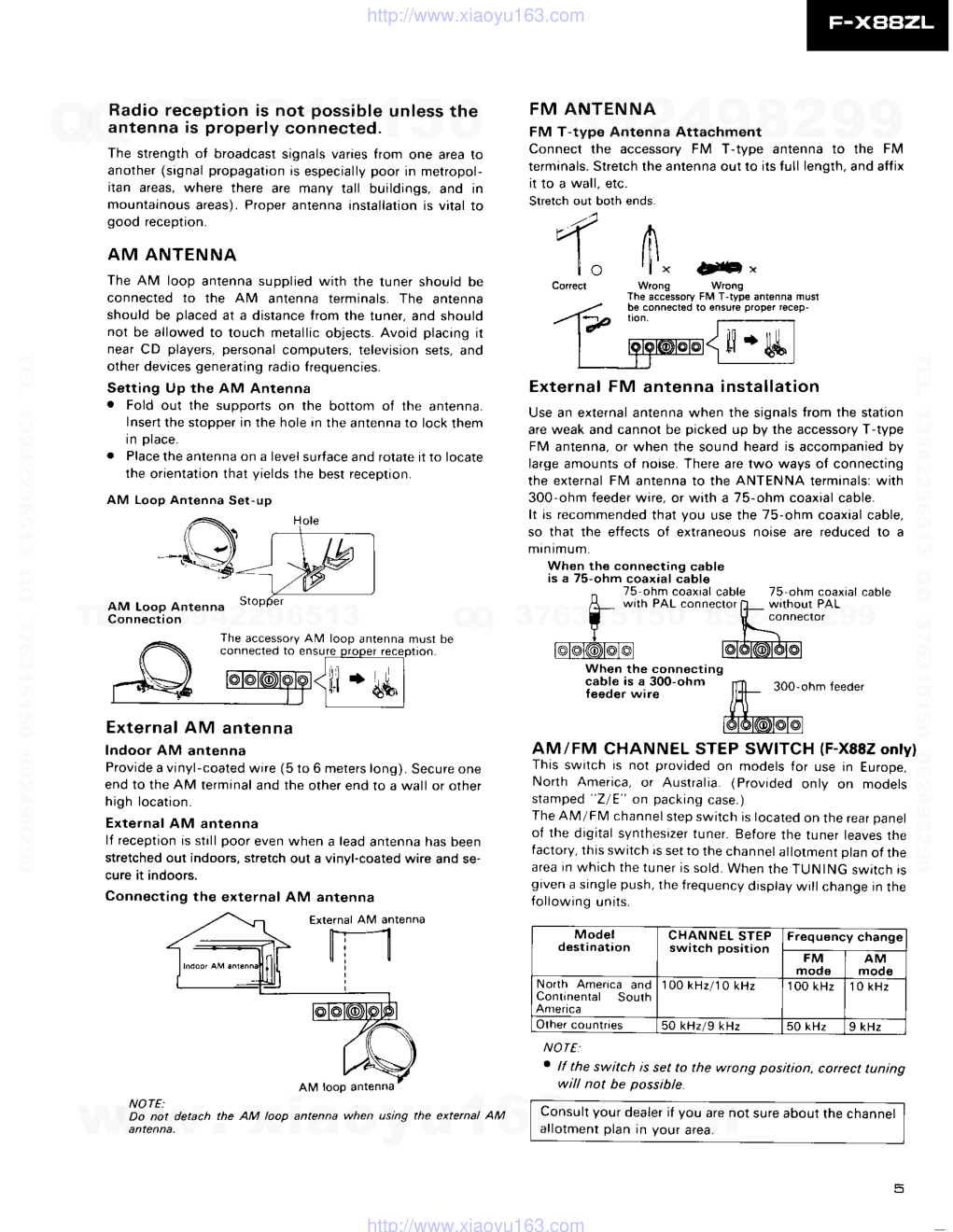
0(U) P",LP.L"\l,F..m' //9, ORDER NO. A R P 1 3 0 6 FM/AM DIGITAL SYNTHESIZER TUNER CONTENTS 1 . S P E C I F I C A T | O N S . . . . . . . 2 2 . p A N E L F A c r L r r r E S . . : . . . . . . . . . . . : . . . . . . . 3 3. EXPLODED VIEWS AND PARTS LIST . . . . . . . . .6 4 . P . C . B O A R D S C O N N E C T I O N D I A G R A M . . . . . . . . 9 5 . S C H E M A T | C D | A G R A M . . . . . . . . . . . . . 1 1 6 . E L E C T R I C A L P A R T S L I S T . . . . . . 1 5 This service manual is applicable to the F-XSSZLIZEB type. As to the other types, please refer to the additional service manual. The AM tuner of the F-XSSZLIZEB type is a two wave'band tuner with MW (medium wave) and LW (long wavel, but the other types are MW only. Ce manuel d'instruction se refire au mode de r6glage en frangais. (p. 21 - p. 231 Este manual de servicio trata del m6todo ajuste escrito en espafiol. lp. 2a - p. 261 FIXBE|z;L MODEL F-X88ZL AND F-X882 COMES IN FOUR VERSIONS DISTINGUISHED AS FOLLOWS: Type Applicable model Powor r€qu irement Destination F.X88ZL F-X882 ZE B o (DC power supply) European continent and United Kingdom zEz o (DC power supply) West Germany z o (DC power supply) General market zroxl B o (DC power supply) Italy o o o o o 7. 8. 8. L P A C K T N G . . . . . . . . 1 7 A D J U S T M E N T . . . . . . . . . 1 8 R E G L A G E . . . . . . . . 2 1 AJUSTE . . .24 PIONEER ELECTRONIC CORPORATION 4-1, Mesuro 1-chome, Meguro-ku, rokyo 153, Japan PIONEER ELECTRONICS SERVICE lNC. P.O. Box 1760, Long Beach, California 90801 U.S.A. TEL: [2]31 835-6177 PIONEER ELECTRONICS OF CANADA, lNC. 505 Cochrane Drive, Markham) Ontario L3R 688 Canada TEL: [416] 479-4411 PIONEER ELECTRONIC IEUROPEI N.V. Keetberglaan 1,2740 Beveren, Belgium fEL: 03/775. 28 . 08 PIONEER ELECTRONICS AUSTRALIA PW. LTD. 178-184 Boundary Road, Braeside, Victoria 3195, Australia TEL: [03] 580-9911 F V o . l 9 8 7 l A N . P r i n t e d i n J a p a n www. xiaoyu163. com QQ 376315150 9 9 2 8 9 4 2 9 8 TEL 13942296513 9 9 2 8 9 4 2 9 8 0 5 1 5 1 3 6 7 3 Q Q TEL 13942296513 QQ 376315150 892498299 TEL 13942296513 QQ 376315150 892498299 http://www.xiaoyu163.com 1. SPECIFICATIONS FM Tuner Section Frequency range. . . . . .87.5 MHz to 108 MHz U s a b l e S e n s i t i v i t y . . . . . . 1 2 . 7 d B f , I H F ( 1 . 2 ! V / 7 5 o h m s ) 50 dB Ouieting Sensitivity. . . . . Mono: 18 dBf l2.2ttY /75 ohmsl Stereo: 38.3 dBf l22.6ttv 175 ohmsl Sensitivity (DlN).... . . Mono 0.9pV/75 ohms Stereo:3t.5gvl75 ohms :':1': :: ):':: ::T I ":'::* ':1:'�1 Mono, i7 dB Stereo: 73 dB Signal-to-Noise Ratio (DlN). . . . .Mono:62 dB Stereo:60 d8 Stereo:0.5% (1 kHz) . . . 60 dB (400 kHz) . . . . . 4 0 d 8 ( l k H z ) dB (30 Hz to 15 kHz) . . . 3 8 d B . . 1 1 0 d 8 . . 300 ohm balanced 75 ohm unbalanced . 650 mV Distortion . . . . . . . MW (AM) Tuner Section Frequency range When 10 kHz stsp. , . , .530 kHz to 1,600 kHz When 9 kHz step . . . . . .531 kHz to 1,602 kHz S€nsitivity (lHF, Loopantenna). . .... . .. . . . 350!V/m S e l e c t i v i t y . . . . . 2 0 d 8 S i g n a l - t o - N o i s e R a t i o . . . . . . . . . . . . . . 4 5 d B l m a g e I n t e r f e r e n c e R a t i o , . , . . . . . , . . 4 0 d 8 l F l n t e r f e r e n c e R a t i o . . . . . . . . . . . . . . 5 0 d 8 Antenna. . . . . . . . Loop Antenna O u t p u t L e v e l { A M 3 0 % M O D ) . . . . . . . 1 5 0 m V LW Tuner Section (For LW-equ ipped models only) F r e q u e n c y r a n g e . . . . . . . 1 5 3 k H 2 t o 2 8 1 k H z Sensitivity (lHF, Loop antenna) . . . . .1500 pVlm Alternate Channel Selectivity. . Stereo Separation Frequency Response . . .... . lmage Interference Ratio .... lF Interlerence Ratio. . . . . . . Antenna Input Output Level (FM 100% MOD) Selectivity . . . . 2 0 d B S i g n a l - t o - N o i s e R a t i o . . . . . . . . . . . . . . 4 5 d 8 l m a g e I n t e r f e r e n c e R a t i o . . . . . . . . . . . 3 0 d 8 l F I n t e r f e r e n c e R a t i o . . . . . . . . . . . . . . 5 0 d B Antenna . , . , . . . Looo Antenna Output Level (AM 30% MOD) 150 mV Miscellaneous Dimensions 360(W) x 56(Hl x 215(D) mm 14-3116(W) x2-3l16(H) x 8-1l2(D) in Furnished Parts FM T-type antenna AM Loop Antenna 2. PANEL FACILITIES TUNER input/output cord Connect lo the TUNER iack of the deck amplitier. FM/AM antenna terminals Antennas must be connocted to those terminalsr otherwise you will not be able to receive stations. See page 5 for details on antenna connections. www. xiaoyu163. com QQ 376315150 9 9 2 8 9 4 2 9 8 TEL 13942296513 9 9 2 8 9 4 2 9 8 0 5 1 5 1 3 6 7 3 Q Q TEL 13942296513 QQ 376315150 892498299 TEL 13942296513 QQ 376315150 892498299 http://www.xiaoyu163.com FM MONO switch / ind icato r Normally this is set to the off position (the FIV MONO indicator go€s off). When noise spoils the reception of an FM program, pr6Es the switch to the on position (the Fl\4 MoNo indicalor will now light). The program ofan FM stereo broadcast will be heard in mono. The setting of tho FM MONO swrtch (on or off) is momorized along with the station's frequgncy in the STATION CALL swrtch9s. When using the preset tuning feature, reception will be in the mode selected wh6n lhe station was memorized. This switch will nol function tor AM (MW or LW) reception. FREOUENCY display Pormits roading thg received frequency at a glance trom lhe display6d figris. The FM band is indicated by MHz, and the AM (MW or LW) band by kHz. TUNING switch This is used to locate the stations. Push either side of this switch; the left side "-" to go to a lower, and the right side " + " to go to a higher lrequency. STEREO indicator This lights wh6n a stereo program has been picked up during an FM broadcast. SELECT (1 -1 2 11 3-241 switch/indicator This switch is used to s6l€ct th6 STATION CALL switches to Mode 1 (1-12) or Mode 2 (13-24). Mode 2 (13-24) is ob- tained when tho switch is oressed 8nd select indicator i8 lit. NOTE: Changing the position ol this switch has no ellect on rcceivet peiomance itself. TUNED indicator This lights to indicate wh€n the finost tuning of a station has b6en achieved. STATION CALL switches These are used to recall preset broadcasting stations and to preset the statton. BAND SELECTOR switch IFor modol F-X882] Each time this switch is pressed, FM or AM reception is selected alternately, FM and MHz lightr FM reception AM and kHz light: AM reception lFor model F-X88ZLl Each time this switch is pressed, FM, MW or LW recep- tion is selected slternatelv. FM and MHz light: FM reception AM and kHz light: MW or LW reception MEMORY switch This switch is used to memorize stations. When the switch is pressed, the frequency indicator will flash. To memorize the frequency of any station, press the station call switch while rhe memory indicalor is lit. 3 www. xiaoyu163. com QQ 376315150 9 9 2 8 9 4 2 9 8 TEL 13942296513 9 9 2 8 9 4 2 9 8 0 5 1 5 1 3 6 7 3 Q Q TEL 13942296513 QQ 376315150 892498299 TEL 13942296513 QQ 376315150 892498299 http://www.xiaoyu163.com Proceed as tollows with the set-up and connections, 1. Place the tuner on top of the cassette tape deck 5. Place the turntable on top of the tuner. amplifier. 6. Connectthe turntable's output cords to the cassette tape 2. Connect the tuner to cassette tape deck amplifier. deck amplitier's PHONO jacks. lf any other stereo compo- 3. Connect the FM antenna and the AM antenna to the nent is to be used, connect it in the same way to the CD or tuner's antenna terminals. VIDEO jacks. lf the model has an AM/FM CHANNEL STEP swirch, 7. Connect the speaker cords lo the SPEAKERS terminals. check whether il is posilioned properly. L Finally, connect the power cord the the AC wall socket. 4. Attach the turntable legs at the left and right ol the cas sette tape deck amplifier�s rear panel. Plug the power cord into the AC wall socket outlet only after all the connections have been completed. Keep the power switch at the OFF position. lllustration not aeolicable to U.K. model. Connecting tho input/output cords a Inserl the plugs securely into the jacks. lmpfoper con- nectaon can lead to sound drsto(ion or malfunctioning. a The white plug is for the left channel connection and the red pl'rg {or the fight channel connectron. Be sure to insert the plugs all the way. White plug Red plug mi# eod Connectingthe strands. . Check that the speaker cords arc secure and will nt become disconnected. NOTE: Do not allow the conductors of the cods to prciect beyond the ter- minals and to come into contact with other conductors. A brcakdown or failurc may occur when conductots touch one Speakel impedance Connect speaker systems with a nominal impedance of bet- ween 6 and 16 ohms. (Left) Sp€aker (Righ0 Video disc play€.. etc Attaching the legs of the turntable Attach the legs accompanying the turntable to the rear panel ot the cassette deck amDlifier. . Be sure lo attach the left (L) and righr (R) legs to their proper posnons. 1 . Insen the guide pins on the legs into the holes in the back ot the cassette deck amplitier. 2. Fasten the legs in place with the screws provided. 3. After connecting the antenna, curely on top ot the legs. mount the turntable se- Turntable leg (Rl www. xiaoyu163. com QQ 376315150 9 9 2 8 9 4 2 9 8 TEL 13942296513 9 9 2 8 9 4 2 9 8 0 5 1 5 1 3 6 7 3 Q Q TEL 13942296513 QQ 376315150 892498299 TEL 13942296513 QQ 376315150 892498299 http://www.xiaoyu163.com Radio reception is not possible unless the antenna is properly connected. The strength of broadcast signals varies from one area to another (signal propagation is especially poor in metropol- itan areas, where there are many tall buildings, and in mountainous areas). Proper antenna installation is vital to good reception. AM ANTENNA The AM loop antenna supplied with the tuner should be connected to the AM antenna terminals. The antenna should be placed at a distance trom the tuner, and should not be allowed to touch metallic objects. Avoid placing it near CD players, personal computers, television sets, and other devices generating radto frequencies. Setting Up the AM Antenna . Fold out the supports on the bottom of the antenna. Insert the stopper in the hole in the antenna to lock them In Dlace. . Place the antenna on a level surlace and rotale it to locate lhe orientation that yields the best receptron. AM Loop Antenna Set-up AM Loop Antenna Conn€ction The accessory AM loop antenna must be FM ANTENNA FM T-type Antenna Attachment Connect the accessory FM T-type antenna to the FM terminals. Stretch the antenna out to its full length, and alfix it to a wall, etc. Stretch out both ends. ',1 "-V a l r l t ill | | AlF ' Cored Wong Wrong The accessorv FM T-tyDe antsnna musl ,..- be connected ro ensure proper rscep- -17 *" t.;_ - I tOOCIron( tl 'lrq I r | L : l External FM antenna installation Use an external antenna when the signals trom the station are weak and cannol be picked up by the accessory T-type FM antenna, or when the sound heard is accompanied bV large amounts oI noise. There are lwo ways of connecting the external FM antenna to the ANTENNA terminals: with 300-ohm feeder wire, or with a 75-ohm coaxial cable. It is recommended that you use the 75-ohm coaxial cable, so that the effects of extraneous noise are reduced to a m i n i m u m . When th€ connecting cable is a 75-ohm coaxial cable ^ 75 ohm coaxial cable 75-ohm coaxial cable A_ wrth PAL.onnector [L_ w'thout PAL I K connecror Y t-\ @@(@@f@l @16l@16l@l When the connocting cable is a 300-ohm n.Tl 3oo.ohm teeder t€eder wrre /,{- dIA ,-,*l@D[@T@l AM/FM CHANNEL STEP SWITCH (F-x882 only) This switch is not provided on models lor use in Europe, North America, or Australia. (Provided only on models stamped "Z/E" on packing case.) The AM/FM channel step switch is located on the rear panel of the digital synthesizef tuner. Before the tuner leaves the tactory, this switch is set to the channel allotment plan ot the area in which the tuner is sold. When the TUN ING switch is given a single push, the frequency display will change in the following units. External AM anten na Indoor AM antenna Provide a vinyl-coated wire (5 to 6 meters long). Secure one end to the AM terminal and the other end to a wall or olher high location. External AM antenna lf reception is still poor even when a lead antenna has been stretched out indoors, stretch out a vinyl-coated wire and se- cure it indoors. Connecting the external AM antenna connecled to enSure proper receplton f ---- t]]] ryf,:c NOTE: Do not detach the AM loop antenna when using the extenal AM Model d€stination CHANNEL STEP switch position Frequsncy change FM mode A M moo€ No(h Ameflca and Conlinental Soulh America 1 0 0 k H z / 1 0 k H z 100 kHz 1 0 k H z Olher countries 50 kHz/g kHz 50 kHz 9 kHz NOTE . lf the switch is set to the wrong position, coftect tunjng will not be possible. Consult your dealer if you are not sure about the channel allotment olan in vour area. www. xiaoyu163. com QQ 376315150 9 9 2 8 9 4 2 9 8 TEL 13942296513 9 9 2 8 9 4 2 9 8 0 5 1 5 1 3 6 7 3 Q Q TEL 13942296513 QQ 376315150 892498299 TEL 13942296513 QQ 376315150 892498299 http://www.xiaoyu163.com 3. EXPLODED VIEWS AND PARTS LIST NOTES: . Pats without part number cannot be supplied. o The A mark found on some component parts indicqtes the importance of the sofety factor of the part. Therefore, when replacing, be sure to use parts of identicol designa- On. o For your parts Stock ControL the fast moing items qre indicated with the marks * * and *. * * GENERALLY MOVES FASTER THAN * This classification shall be adjusted by each distributor because it depends on model number, temperuture, humidiry, etc c Parts marked by "A" are not always kept in stock. Their delivery time may be longer than usual or thev mav be unavailable. . hrts List Mlrk No, Parl No. D.ac.iptio|i 1 . 4. 7, 10. 1 1 . AMB1146 AACr006 AAD1,I07 AAKl181 AAK1189 ANE1062 AMRIOO2 A8A-298 ABAlOO9 AW21247 ADE t O24 Front psn6lassombly Knob cap Pu3h knob lND. pan6l r- L l t€r Bonnet csse Foot €ssembly Scr6w Scrow Tun€r sasombly Connection cable LED a$embly Tuning assembly Chassis 6 www. xiaoyu163. com QQ 376315150 9 9 2 8 9 4 2 9 8 TEL 13942296513 9 9 2 8 9 4 2 9 8 0 5 1 5 1 3 6 7 3 Q Q TEL 13942296513 QQ 376315150 892498299 TEL 13942296513 QQ 376315150 892498299 http://www.xiaoyu163.com 3 2 1 A B C D 3 2 1 www. xiaoyu163. com QQ 376315150 9 9 2 8 9 4 2 9 8 TEL 13942296513 9 9 2 8 9 4 2 9 8 0 5 1 5 1 3 6 7 3 Q Q TEL 13942296513 QQ 376315150 892498299 TEL 13942296513 QQ 376315150 892498299 http://www.xiaoyu163.com 5 4 A B c D 4 6 5 " [ - www. xiaoyu163. com QQ 376315150 9 9 2 8 9 4 2 9 8 TEL 13942296513 9 9 2 8 9 4 2 9 8 0 5 1 5 1 3 6 7 3 Q Q TEL 13942296513 QQ 376315150 892498299 TEL 13942296513 QQ 376315150 892498299 http://www.xiaoyu163.com @ 1 TUNING ASSEMELY 4. P.C. BOARDS CONNECTION DIAGRAM 9P CONNECTOR ADE1O24 +12V --< 4 BACK UP +B- < 5 AC GND--<6 REMOTE CN --< 7 3 A GND --< 2 R c h < 1 Lch --< 3 NC--<8 AC-<9 TUN E R ASSEMBLY (AWZ1247I B c D 3 2 1 www. xiaoyu163. com QQ 376315150 9 9 2 8 9 4 2 9 8 TEL 13942296513 9 9 2 8 9 4 2 9 8 0 5 1 5 1 3 6 7 3 Q Q TEL 13942296513 QQ 376315150 892498299 TEL 13942296513 QQ 376315150 892498299 http://www.xiaoyu163.com 6 5 4 A B - c 4 6 5 www. xiaoyu163. com QQ 376315150 9 9 2 8 9 4 2 9 8 TEL 13942296513 9 9 2 8 9 4 2 9 8 0 5 1 5 1 3 6 7 3 Q Q TEL 13942296513 QQ 376315150 892498299 TEL 13942296513 QQ 376315150 892498299 http://www.xiaoyu163.com 5 4 3 TUNER ASSEMBLY I AW 21247 I O 1 1 7 : F M + B S W I T C H I N G I C l O ] . A M / F M I F D E T 1C101 l1/2) *'1"""ITf, *q:"* T:d 9--so'* O 1 0 4 : F M L O C A L O S C t c 1 0 1 t 2 / 2 1 M Bd- c€ loo0 0 1 0 1 r F M R F A M P O 1 0 2 : F M M I X E R oto2 9-it1*. u."" l C 1 0 2 : M P X l C Q t o t zzq L. J i o r t s , n e s e r O 1 1 6 : M W + B S W I T C H I N G O 1 2 0 L W + B S W I T C H I N G IC103 d fr 1 C 1 0 3 : P L L l C 0 1 0 6 , 1 0 7 D c A M P 0112,113 | DTC143ES 0 r 1 4 , 1 r 6 , oll7,12o : oTA143€5 Q115,121 : DTC124ES Q1ta,119 : 2SC2878 0 r o 1 , 1 o 2 : l T T 3 r o DtO3,1O4,lO9 : SVC321C3 6r svc32103 0lo5-1o4, 0rr1,113, fl4, 0118-t2l : lSst31 D110,501 : R07.5€SE D112 : R06.2ESB Dll6.1l7 : lSSa5 O ] 1 4 T U N E I N D D R I V E R IC101 : LA1?65S IC10? : AN7470P IC103 : LM700r IC1O4 : P05O47 0rO1 : ?X241 oto? : 2SC2786 oro3,1o4 | 2sc266€ OlO5 : 2SXl6l Q1O6 : 2SX246 O1O7 : 2SC|T4OSLI 0roa, to9, Ollt : 2SC174OS O11o : 2SA933s 1 C 1 0 4 : T MIC L RESIST0RS, lndicoted in o. vaw. v4w,15x loteronce untess olherwise noled k; ko. M; Mo. (F):11x. (G)r izx.(K): rlox. (M)r 12ox toteronce 2 , C A P A C I T O R S : hdicoled in copocity (fF)/vottoge (V) unless oiherwise n0lad pr pF. Indicolion withoul vottoge is 5OV excepl etecirotyiic copocilor f,. VOLTAGE. CURRENT: lf; DC votloge {V) ol no inpul siqnot E ,signot votlooe 01 FM 4ooHz 75kHz DEV. 4. OTHERS: 5 {: slgno( rouie. O : Adjusthg polnl. The A mork tound on some component porls Indlcoles the lmporlonce of the solely locior of lhe porl. Theretore. when reptoclng. be sure lo use pdris of ldenllcol deslgnollon. horked copocllors ond reslstors hove porTs numbers. Thls ls the bdslc scienotlc dlogron. bul lhe octuot clrcult moy vory due lo lhprovemenls In desl9n. SW|TCHES: s101 : I /13 s102 : ?/14 s103 : J/15 s104 : 4/16 s105 : 5/17 s106 | 6/14 S 1 O 7 ' 7 / 1 9 s10a I a/20 s109 : 9/21 s110 . ,o/22 Sfl : l1l23 s112 . 12/24 1-12/13-24 FM MdO 'UNINC - TUNING + BArc SELECIOR s50r s502 s40r s402 s405 s404 5 4 3 3 " : . : : : : : E a 3 ! 3 o 3 ! € g s t g t ! s I - l i a g t " . Y T Y Y Y Y Y Y Y Y Y Y Y Y Y Y Y Y Y Y Y Y Y ; Y ] www. xiaoyu163. com QQ 376315150 9 9 2 8 9 4 2 9 8 TEL 13942296513 9 9 2 8 9 4 2 9 8 0 5 1 5 1 3 6 7 3 Q Q TEL 13942296513 QQ 376315150 892498299 TEL 13942296513 QQ 376315150 892498299 http://www.xiaoyu163.com 7 6 5 r c 1 0 2 M P X r C O ] 0 8 , 1 0 9 B U F F E R TUNING ASSEMBLY 9P CONNECTm aElo24 ' + l ^ "1.r2rc | """7 rCtr2 5 . S W I T C H E S : stot : I /15 s102 ' 2/14 srcf : 5/15 hportcnce Src4 : 4/16 hg. De sure Sp5 : 5/17 SP6 : 6/14 s107 | 7/19 s10a : a/20 moy vory due S$9 : 9/21 sao | 10/22 Sfi : r/23 511? . 1?/?4 S3O1 : l-12113-24 S3O2 : FM MdO S4O1 : TUNNC - 5402: rUNNG + s4O3 : EMmY s4O4 : BANo SELECTOR 7 6 5 lH I or ro vurt IFG;- i** itn*''"'"" ,"?-fd?i 1C101 l1/21 + W T € ICIO4 6?t8h rdo )E 0 1 ] 4 T U N E I N D D R I V E B o114 r c r 0 4 . r u N E a c o N r B o L ( ' i l / - - MICROCOMPUTEF Yo!13 " 3 3 € s s t s t l s * 5 ! " : C " Y Y Y Y Y Y Y Y Y Y Y g Y I LED ASSEMBLY www. xiaoyu163. com QQ 376315150 9 9 2 8 9 4 2 9 8 TEL 13942296513 9 9 2 8 9 4 2 9 8 0 5 1 5 1 3 6 7 3 Q Q TEL 13942296513 QQ 376315150 892498299 TEL 13942296513 QQ 376315150 892498299 http://www.xiaoyu163.com External Appearances of Transistors and l0s 2SC2878 Type No 25A933S 2SC1 7405 2SC17405LN Type No hre LA1 2655 2SC2786 DTA143ES DTCl 24ES DTC143ES 2SK1 61 25K241 AN747OP LM7001 Lot No www. xiaoyu163. com QQ 376315150 9 9 2 8 9 4 2 9 8 TEL 13942296513 9 9 2 8 9 4 2 9 8 0 5 1 5 1 3 6 7 3 Q Q TEL 13942296513 QQ 376315150 892498299 TEL 13942296513 QQ 376315150 892498299 http://www.xiaoyu163.com 6. ELECTRICAL PARTS LIST NOTES: . Parts witho paft number cannot be supplied. . Parts marked by "A" are not always kpt in stock. Their delivery time may be longer than usual or they may be unavail- able. o The A mark found on some component parts indicates the importance of the safety factor of the paft. Therefore, when replacing be swe to use parts of identical designation. c For your parts Stock Control, the fast moving items are indicated with the marks * * ond * . * * GENERALLY MOVES FASTER THAN* This classification shall be adjusted by each distibutor because it depends on model number, temperature, humidiry, etc. c When ordering resiston, fnt convert resistance values into code form as shown in the following exqmple' Ex. I When there qre 2 effective digits (any digit apa ftom 0), such as 560 ohm and 47k ohm (tolerance is shown by l - 5%,andK-10'%). 5flA 56x t0t 561.......................... RDl/4p56@m J 17kA 47 x 10r 473.......................... RDt/4ps@A6 J 0.59 0R5...............................................RN2HO8trK 1A 01o................................................ Rs/Po tr @ K Ex. 2 When there are 3 effective digits (such as in high precision metal frlm resistors). 5.62k4 562x 101 5621........................ RN1/4SR 6 6 E tr l. Miscellaneous Parts M.rk Symbol & D.scription s1,l[TcHES Merk Symbol&Descriplion Part No. Prrt No. Tuner asseftboy Tuning alsembly LED assembly Tu ner Assembly (AW21247 | SEMICONDUCTORS M..k Symbol & O.scription AWZ1247 P.rt No. r r SlOl - Sl'12 Tact switch {STATION) COILS, TRANSFORMERS AND FILTERS M.rk Symbol & DGcrifiion ASG.712 P.rt No. *t tc102 r * t c 1 0 1 * * rc103 ** tcr04 It 01'�t4, 0116, 0117, 0120 r * o 1 1 5 , O 1 2 l r t 0112, 01'�t3 r i 0 1 . t o rr 0108, 0109, 0111 r * 0 1 0 7 t r 0103, 0104 *t 0102 r t 0 1 1 8 . 0 1 1 9 *t 0105 r * 0 1 0 1 ** 0106 r D101, D102 t D't 12 * D110, D501 * D103, 0104, D109 * D105 - O't08, Dl11, D113, * D 1 1 4 , D ' t 1 8 - D 1 2 1 r 0 1 1 6 , D l t 7 L1O5 FM DET coil L101, L108 Axial inductor AN747OP LA12655 Ll\,17001 PD5047 DTA143ES DTC124ES DTCI43ES 2SA933S 2SC17405 2SC17405LN 2SC266a 2SC27A6 2SC2878 2SK 16'l 2SK241 2SK246 tTT310 RD6.2ESB RD7.5ESB svc32l c3 (svc321D3) 1SS131 1SS85 Axial inductor Inductor AM ANT transtormer FM RF trsnsformer LW ANT transformer FM malching transformer FM ceramic lilter FM c€ramic tilter FM bandpass filter AM cer€mic filter L107 L102 L 1 1 0 Ll09 L106 T103 T 101 T104 f 102 F103 F 10�2 F 1 0 1 F 104 CAPACITORS AM OSC coil FM coil LW OSC coil ATB.,I14 ATC1003 ATD-023 ATE-079 LAU2 R2IVI LAU221K LT 4472J ATB,O95 ATC-194 ATD 1OO2 ATE463 ATF-107 ATF-119 ATF.I55 ATF.2OA Psn No. Symbol & O..criprion Cl63 {22oo0pF/5.5V) TCl03 Ceramic trimmer TC101, TC102 Ceramic trimmer clr6, c181 c l 1 3 c106 c101 c l l l cl08, clr4, c't59, cl60, c174 cl69, Cl70 ACH1023 ACM.020 ACM426 cccsL101J50 ccDcH0loc50 ccDcH020c50 ccDcH040c50 ccDcHo80D50 ccocHl50J5o ccocH270J50 www. xiaoyu163. com QQ 376315150 9 9 2 8 9 4 2 9 8 TEL 13942296513 9 9 2 8 9 4 2 9 8 0 5 1 5 1 3 6 7 3 Q Q TEL 13942296513 QQ 376315150 892498299 TEL 13942296513 QQ 376315150 892498299 http://www.xiaoyu163.com Symbol & Oercrifiion OTHERS tla.k Symbol & D.scriplion Part No. cl to c176 cl04 c107 c128 cl09 c117 cl30 cl46 c182 c't41, cl55, Cl57, Cl71, Cl79 c121, C145 c164, Cl65 cl80 c124, Cl6t, C't 68 cr39, cl50, c151 c134, C144 c122, C127, C131 cl35 cl36, C166 cl54, Cl56 cl44, cl49 cl3a cr52, cl53 cl19, C132, C140 cl20 c133, Cl43, Cl47 c137 c 1 1 2 ccDcH330J50 ccDcH560Js0 ccDRH 180J50 ccDsLl0'tJ50 ccDsL221J50 ccDTH150J50 ccDUJ120J50 CEANPO'IOM5O CEASR22M5O cEASOR t M50 cEASO10M50 CEASl R5MsO cEAS100M25 cEAS101M10 cEASl0l M16 CEA52R2MSO CEA53R3M5O cEA5330M16 CEA54RTM5O cEA5470M10 cEA5470M16 cKcYB102K50 cKcYB222K50 cKcYB332K50 cKcYF 103250 cKcYF223250 cKcYF473250 cKcYX473M25 CKDYB 102K50 cl02, cl03, c105, c123, C172, C113 CKDYF 103250 cl 15, Cl25, C f 26, C129, C176, C178 CKDYF223Z50 Antenna terminal (4P) (PAL) * V101 Fluorescent tube t X102 Ceramic resonator t X101 Crystel rosonator Tuning Assembly SEMICONDUCTORS Mark Symbol&Deacription Prrt No. AKAlOO2 AAV-017 ASS-O30 ASS1005 P.rt No. * O4O2 LED assembly * D401 LED €ssembly S:WITCHES M!.k Symbol&O.scriplion AELl OO9 AEL1024 Prrt No. r t 3401 - S4O4 Tact switch /TUNTNG-, TUN rNG+l \MEMoRY. BAND l RESISTORS Mark Symbol&Description ASG-7 r 1 Part No. R401 LED Assembly SEMICONOUCTORS Merk Symbol & Descripiion RD1/8PM332J Part No. AEL1O24 Parl No. cKDYF473Z50 cosA301J50 cosA431J50 cosA471J50 cKDYF I 03250 Prrt No. * D3O1, D3O2 LED assembly swtTcHEs M.rk Symbol & D..cription cl 58, cl62 c177 c't l8 c142 c183 RESISTORS Mtrk Symbol & Oarctiptiofn t t 5301, 5302 Tact switch (FM MONO, STER EO) ASG-71'l t VR101 S€mi-f ixed 14.7kc)) VRTB6V5472 R226 RO112PM220J R 162, R f 67, Rl68, R l70,A171,R225 RD1l4P[,ltr tr trJ Other resistors RDl /8PMtr tr OJ www. xiaoyu163. com QQ 376315150 9 9 2 8 9 4 2 9 8 TEL 13942296513 9 9 2 8 9 4 2 9 8 0 5 1 5 1 3 6 7 3 Q Q TEL 13942296513 QQ 376315150 892498299 TEL 13942296513 QQ 376315150 892498299 http://www.xiaoyu163.com 7. PACKING . Parts List of Packing M..k No. P.n No. Oaacription 1 . 4. 5 t . AHD,I164 AHA1O45 ARH.Os1 AEAIOO2 Packing case Side p.d Supplomentrry instr!ctions Antonna s6t Packing rhoet www. xiaoyu163. com QQ 376315150 9 9 2 8 9 4 2 9 8 TEL 13942296513 9 9 2 8 9 4 2 9 8 0 5 1 5 1 3 6 7 3 Q Q TEL 13942296513 QQ 376315150 892498299 TEL 13942296513 QQ 376315150 892498299 http://www.xiaoyu163.com 8. ADJUSTMENT PREPARATION o Connect TP15 (cND) with TP17 (GND). r Supply DC 12V between TP18 and TP17, and between TP13 and TP15 (see Fig.8-1). FM Tuner Adlustment o Make the wire connections as shown in Fie. 8-2. r Set the function to FM. { ' 1 ) S t e r e o M o d u l a t i o n : M a i n l k H z L + R i 6 8 . 2 5 H 2 d e v . P i l o t l g k H z t 6 . 7 5 k H z d e v . {'3) The method of adjustment in step 2 is different for F -xggZlZEZ rype. For details, refer to service manual (ARp1341) for tvoe F-XaAZIZEZ. MW Tuner Adjustment o Make the connections as shown in Fie. 8-3. . Set the function to MW. LW Tuner Adiustment o Make the connections as shown in Fie. 8-3. o Set the function to LW. . F-XSSZLIZEB type only. Step No. FM SG {1kHzt75kHz dev.) F.X88ZL Reception Frequency Display Adjustm€nt Frequency (MHzl Level {dB/) Adjustment Location Specifications l 98.0 60 98.0MHz 1 1 0 5 Adjust so that DC voltage is 0V t 0.1V for TP28 (TMETER 1) and TP26 lTMETER 2). 2 ( ' 3 ) 98.0 60 98.0MHz T 1 0 1 , T 1 0 2 Adiust the output terminal (TPs: L ch, TP7: Rch) voltage to the maxjmum. 3 98. OM Hz V R l O l Ground TP25 through the 22OlF capacitor, and adjust the frequency of TP8 ro 76kHz 12O0Hz. 4 ^^ ^ '1 (slereo 60 98. OM Hz r102 Adjust the output terminal {TP5: Lch, TP7: Rch) distonion to the minimum. Step No. AM SG (400H2,30% modulation) F-X88ZL Reception Frequency Display Adiustment Frequency lkHz) L€vel {dBp} Adjustment Location Specilications 1 5 3 l k H z 1 1 0 7 Adjust TP3 (VT) to 1 .3V 1O.'l V. 2 'I602kHz T C 1 0 2 Adjust TP3 {VT) to 1OV 10.5V. 3 603 Level at which output is not saturated. 603lHz T 1 0 3 ( ' 2 ) Adjust the output terminal (TP5: L ch, TP7: R ch) voltage to the maximum, 4 r 395 1395LHz T C r 0 l ( * 2 ) ('2) F104 is adjusred for F-X882/ZlOXlB tvpe. www. xiaoyu163. com QQ 376315150 9 9 2 8 9 4 2 9 8 TEL 13942296513 9 9 2 8 9 4 2 9 8 0 5 1 5 1 3 6 7 3 Q Q TEL 13942296513 QQ 376315150 892498299 TEL 13942296513 QQ 376315150 892498299 http://www.xiaoyu163.com itep No. AM SG l4OOHz,3Oo/o modulationl F-X88ZL Reception Frequency Display Adjustment Frequency (kHzl Level (dBrl Adjustment Location Specif ications 1 281kHz L 1 1 0 Adjust TP3 (VT) to 5.2V. 2 164 Level at which output rs not saturated. 164kHz T 1 0 4 Adjust the output terminal (TP5: L ch, TP7: R ch) voltage to the maximum. ? 254 254kHz T C 1 0 3 rP1.(GND) o q o-"'' o \ \ rP17{GND) L'o5[sIo 1rc7[o TUNER ASSEMBLY I AWZ\247 \ Fig. 8-1 Adjustment point www. xiaoyu163. com QQ 376315150 9 9 2 8 9 4 2 9 8 TEL 13942296513 9 9 2 8 9 4 2 9 8 0 5 1 5 1 3 6 7 3 Q Q TEL 13942296513 QQ 376315150 892498299 TEL 13942296513 QQ 376315150 892498299 http://www.xiaoyu163.com OUTPUT (L, R} I *,--, L_j I counter I t@ Fig. 8-2 FM Tuner Connection AM antenna terminal Fig. 8-3 AM Tuner Connection 20 www. xiaoyu163. com QQ 376315150 9 9 2 8 9 4 2 9 8 TEL 13942296513 9 9 2 8 9 4 2 9 8 0 5 1 5 1 3 6 7 3 Q Q TEL 13942296513 QQ 376315150 892498299 TEL 13942296513 QQ 376315150 892498299 http://www.xiaoyu163.com 8. REGLAGE PREPARATIFS o Raccorder TP15 (Tene) ri TP17 (Tene). . Fournir un courant continu de 12 V entre TP18 et TP1?, et entre TPl3 et Tplb (voir Fig. 8-1). Reglage du tuner FM o Effectuer les connexions des fils de la fagon indiqu6e dans la Fig. 8-2. . R6gler la fonction sur FM. ('1) Modulatjon st€r6o: D€viataon principale de I kHz G + D 168,25H2 D6viation pilote de lgkHz a 6,75kHz ('3) La mithode de rdglage d l'drape 2 diffdre pour le F-X88Z|ZEZ. Pour de plus amples d6tails, se reporter au mod€ d'emploi (ARPl341) du F-X8SZ|ZEZ. Reglage du tuner MW r Effectuer les connexions comme indiqu6 dans la Fig. 8-3. o R6gler la fonction sur MW. R6glage du tuner LW . Effectuer les connexions comme indiqu6 dans la Fig. 8-3. r R6gler la fonction sur LW. . F -X88ZL I ZEB uniquement. FM SG {1kHzt 75kHz d6v.l F.X88ZL Attichago de fr6quence de 16c6ption Rdglage F16qu€nce lMHz) Niveau ldBpl Lieu d€ r6glage Caract6ristiques 1 98,0 60 98,OMHz 1 1 0 5 Aiuster de telle fa9on que la tension CC soit de OV a 0,1V pour TP28 (TMETER 1) et TP26 (IMETER 2). (- 3) 98,0 60 98.0MHz T 1 0 1 , T 1 0 2 Ajuster la tensjon de la borne de sortie (TPs: canal gauche, TP7: canal droit) au maximum. 3 98,0MHz V R 1 O 1 Mettre a la terre TP25 en passant par le capaciteur de 22O lF, et ajuster la lr6quence de TP8 a 76kHz !2OOHz. 98,O * 1 (modu lation st6r6o) 60 98,OMHz r102 Ajuster la distortion de la borne de sortie (TP5: canal gauche, TP7: canal droit) au minimum. Etape AM SG l/rOOHz,30% modulationl F-X88ZL Aftichage de tr6quence d6 .6ception R6glage Fr6quence(kHzl Niveau (dBrl Lieu de .6glage Caract6ristiques 1 531kHz L 1 0 7 Ajuster TP3 (VT) sur 1 ,3V t O,1 V. 2 1602kHz T C r 0 2 A,uster TP3 {VT) sur 'l0V a0,5V. 3 603 Niveau auquel la sortie n'est pas saturee. 6O3lHz T 1 0 3 ( * 2 ) Ajuster la tension de la borne de sortie {TP5: canal gauche, TP7: canal droit) au maximum. 4 1395kHz T C r 0 1 ( . 2 ) l'21 F104 esr r6gld pour le type F.X88Z/Z|OX1B. www. xiaoyu163. com QQ 376315150 9 9 2 8 9 4 2 9 8 TEL 13942296513 9 9 2 8 9 4 2 9 8 0 5 1 5 1 3 6 7 3 Q Q TEL 13942296513 QQ 376315150 892498299 TEL 13942296513 QQ 376315150 892498299 http://www.xiaoyu163.com Etap6 AM SG l4OOHz,30% modulation) F-X88ZL Atfichage de fr6qu€nce de r6ception Reglage Fr6quence{kHzl Niveau (dBt) Lieu de 169lage Caract6ristiques 281kqz L l 1 0 Aiuster TP3 (VT) sur 5,2V 2 164 Niveau auquel la sortie n'est pas saturde. 164kHz T 1 0 4 Ajuster la tension de la borne de sortie (TPs: canal gauche, TP7: canal droit) au maximum. 3 254 254kHz T C 1 0 3 Fig. 8-1 Positions de 169lage 22 www. xiaoyu163. com QQ 376315150 9 9 2 8 9 4 2 9 8 TEL 13942296513 9 9 2 8 9 4 2 9 8 0 5 1 5 1 3 6 7 3 Q Q TEL 13942296513 QQ 376315150 892498299 TEL 13942296513 QQ 376315150 892498299 http://www.xiaoyu163.com SORTIE {G, D} Borne d'antenne FM de 300 ohms l-.*- L_l I de tr6quence I I r-t Ll vor,.e,'" I I nume que I Fio.8'2 Connexion du tuner FM Borne d'antenne AM Fig. 8-3 Connexion du tuner Al\4 www. xiaoyu163. com QQ 376315150 9 9 2 8 9 4 2 9 8 TEL 13942296513 9 9 2 8 9 4 2 9 8 0 5 1 5 1 3 6 7 3 Q Q TEL 13942296513 QQ 376315150 892498299 TEL 13942296513 QQ 376315150 892498299 http://www.xiaoyu163.com 8. AJUSTE PREPARATIVOS o Conecte TP15 (mam) con TP17 (masa). r Aplique 12V CC entre TP18 y TP1?, y entre TP13 y TPJ.5 (consulte la Fig. 8-l). Ajuste del sintonizador de FM o Realice las conexiones como se muestra en la Fig. 8-2. . Ponga el selector de funci6n en FM. (* 1i Modulacidn est6reo: Prancipal l kHz canal izquierdo + canal derecho ! 68,25H2 de desviaci6n Piloto 1gkHz l6,7skHz de desviacidn (*3) El m6todo de ajusle del paso 2 es diferente para el ripo F-X88Z|ZEZ. Con rcspec\o a los detalles, consulte el manual de servicio (ARP1341) parc el ripo F-><882/2E2. Aiuste del sintonizador de MW o Realice las conexiones como se muestra en Ia Fig. 8-3. o Ponga el selector de funci6n en MW. (*2) F104 se ajusta para el tipo F-X882/ZlOX1B. Ajuste del sintonizador de LW o Realice las conexiones como se muestra en la Fig. 8-3. o Ponga el selector de funci6n en LW. r Tipo F-X88ZL/ZEB solamente. FM SG l1kH2175kHz dev., F-X88Zt_ Frecuenclm€tro de recepci6n Ajust€ paso Frecuancia lMHzl Nivel {dBpl Luga. de aiuste Esoecilicacionog 98.0 60 98,0MHz 1 1 0 5 Aiuste de forma que la tensidn de CC sea de 0V 10,1V para TP28 {TMETFF 1) y TP26 ITMETER 2). 2 98.0 60 98.0M Hz T 1 0 1 , T 1 0 2 Aiuste la tensi6n del terminal de salida (TP5: canal izquierdo, TP7: canal derecho) al m6ximo valor. 3 ('3) 98,OMHz V R l O 1 Ponga TP25 a masa a trav6s de un c apacitot de 22O tF, y ajuste la lrecuencia de TP8 a 76kHz l2OOHZ. 4 98,0 * 1 (modula- ci6n est6reo) 60 98,0MH2 r 102 Ajuste la distorsi6n del terminal de salida lTP5r canal izquaer- do, TP7: canal derecho) al mlnimo est6reo) AM SG i4ooHz.30% modulation) F-X88ZL Frecuencimotro de recepci6n Aiuste paso Frecuencia (kHzl Nivel ldBrl Lugar de ajuste Especiticaciones 1 5 3 1 k H z 1 1 0 7 ajusteTP3 lvT) a 1,3V 10,1V. 2 1602kHz T C 1 O 2 Aiusre TP3 (VT) a loV I o,5V. 3 603 Nivel en el que la salida no se satura 603kHz T 1 0 3 t * 2 ) Aiuste la tensidn del terminal de salida (TP5: canal izquierdo, TP7: canal derecho) al m6ximo valor. 4 1395kHz T C 1 0 1 { * 2 ) 24 www. xiaoyu163. com QQ 376315150 9 9 2 8 9 4 2 9 8 TEL 13942296513 9 9 2 8 9 4 2 9 8 0 5 1 5 1 3 6 7 3 Q Q TEL 13942296513 QQ 376315150 892498299 TEL 13942296513 QQ 376315150 892498299 http://www.xiaoyu163.com Uo.do AM SG l4OOHz,30% modutarion) F-X8aZL Frocuencimetao de recepci6n Ajuste paso Frecuencia lkHzl Nivel ldBrl Lugar de aiuste Especiticaciones 1 281kHz L l 1 0 Ajuste TP3 (VT) a 5,2V. 2 1 6 4 Nivel en el que la salida no se satura '164kH2 T 1 0 4 Ajuste la tensi6n del terminal de salida TP5: canal izouierdo. TP7: canal derecho) al rndximo valor. 3 254 254kHz T C 1 0 3 a,ou @o a,otQ Fig, 8-1 Posiciones de ajuste www. xiaoyu163. com QQ 376315150 9 9 2 8 9 4 2 9 8 TEL 13942296513 9 9 2 8 9 4 2 9 8 0 5 1 5 1 3 6 7 3 Q Q TEL 13942296513 QQ 376315150 892498299 TEL 13942296513 QQ 376315150 892498299 http://www.xiaoyu163.com Salida (Canal izquierdo y derecho) Terminal de antena de FM de 3O0 ohmios @, ,@ Fig. 8-2 Conexiones del sintonizador de Fl\4 r Terminal de antena de AIM Fig. 8-3 Conexiones del sintonizador de AM www. xiaoyu163. com QQ 376315150 9 9 2 8 9 4 2 9 8 TEL 13942296513 9 9 2 8 9 4 2 9 8 0 5 1 5 1 3 6 7 3 Q Q TEL 13942296513 QQ 376315150 892498299 TEL 13942296513 QQ 376315150 892498299 http://www.xiaoyu163.com ADVARSEL ADVARSEL! Lithiumbatteri. Eksplosionsf are. Udskitt- ning ma kun loretages af en sagkyndig, og som beskrevet i servicemanualen. Derme advarsel or angivet pa produktet €ller i brugsvejtedningen. Ved udskiftning af lithium banerierne folges nedensldende anveisning. Batterieme ma kun udskiftes med batterier af samme type og m@rke. WARNING! Lilhium batteries. Danger of explosion. Replacement must be done by qualffied personnel and only by following the instructions given in the service manual. This waning is stated on the product or in the operating instructions. When replacing the lithium batteries, follow the note below. The batteries must be replaced only by batter- ies of the same lvDe and manufacrure. 27 www. xiaoyu163. com QQ 376315150 9 9 2 8 9 4 2 9 8 TEL 13942296513 9 9 2 8 9 4 2 9 8 0 5 1 5 1 3 6 7 3 Q Q TEL 13942296513 QQ 376315150 892498299 TEL 13942296513 QQ 376315150 892498299 http://www.xiaoyu163.com
版权声明
1. 本站所有素材,仅限学习交流,仅展示部分内容,如需查看完整内容,请下载原文件。
2. 会员在本站下载的所有素材,只拥有使用权,著作权归原作者所有。
3. 所有素材,未经合法授权,请勿用于商业用途,会员不得以任何形式发布、传播、复制、转售该素材,否则一律封号处理。
4. 如果素材损害你的权益请联系客服QQ:77594475 处理。