先锋PIONEER F-208音响电路图
 "先锋PIONEER F-208音响电路图-0")
 "先锋PIONEER F-208音响电路图-1")
 "先锋PIONEER F-208音响电路图-2")
 "先锋PIONEER F-208音响电路图-3")
 "先锋PIONEER F-208音响电路图-4")
 "先锋PIONEER F-208音响电路图-5")
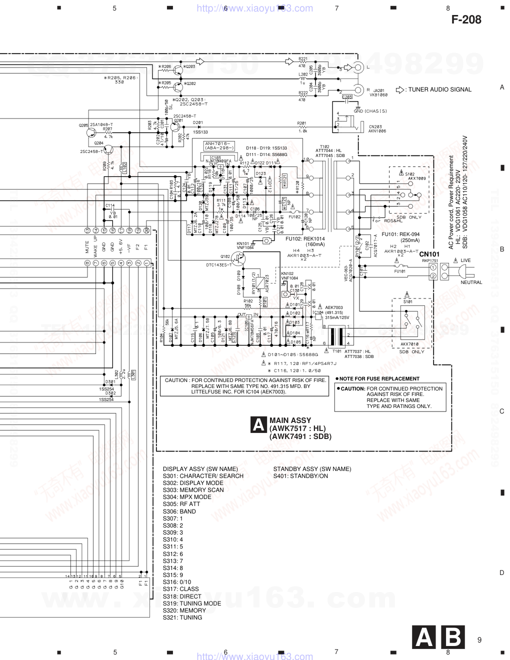
 "先锋PIONEER F-208音响电路图-6")
 "先锋PIONEER F-208音响电路图-7")
 "先锋PIONEER F-208音响电路图-8")
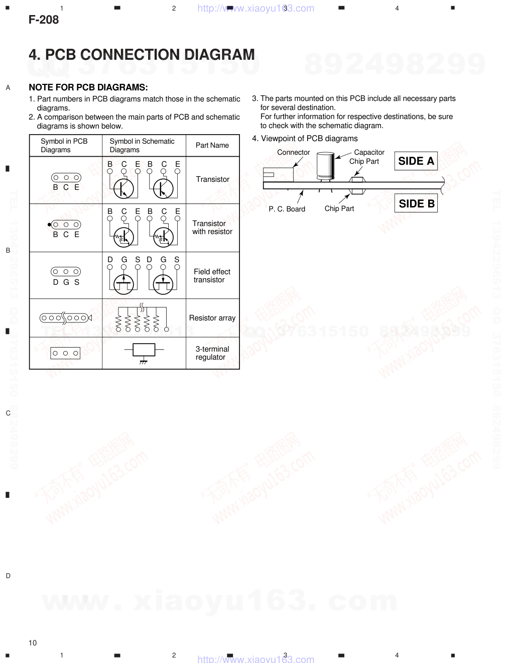 "先锋PIONEER F-208音响电路图-9")
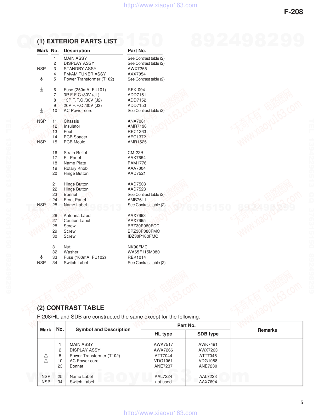
ORDER NO. PIONEER ELECTRONIC CORPORATION 4-1, Meguro 1-Chome, Meguro-ku, Tokyo 153-8654, Japan PIONEER ELECTRONICS SERVICE, INC. P.O. Box 1760, Long Beach, CA 90801-1760, U.S.A. PIONEER ELECTRONIC (EUROPE) N.V. Haven 1087, Keetberglaan 1, 9120 Melsele, Belgium PIONEER ELECTRONICS ASIACENTRE PTE. LTD. 253 Alexandra Road, #04-01, Singapore 159936 � � � � � � � � � �PIONEER ELECTRONIC CORPORATION 1999 RRV2161 T – ZZE JUNE 1999 Printed in Japan FM/AM DIGITAL-SYNTHESIZER TUNER F-208 CONTENTS 1. SAFETY INFORMATION ..................................... 2 2. EXPLODED VIEWS AND PARTS LIST ............... 3 3. BLOCK DIAGRAM AND SCHEMATIC DIAGRAM ......................................................... 6 4. PCB CONNECTION DIAGRAM ......................... 10 5. PCB PARTS LIST .............................................. 14 6. ADJUSTMENT................................................... 16 7. GENERAL INFORMATION ................................ 17 7.1 IC ................................................................. 17 8. PANEL FACILITIES AND SPECIFICATIONS..... 18 THIS MANUAL IS APPLICABLE TO THE FOLLOWING MODEL(S) AND TYPE(S). Type Model F-208 Power Requirement HL O AC220 - 230V SDB O AC110/120 - 127/220/240V With the voltage selector Remarks STANDBY/ON RF ATT MPX CHARACTER BAND CLASS DIRECT TUNING TUNING MEMORY 1 2 3 4 5 6 7 8 9 0/10 FM/AM DIGITAL-SYNTHESIZER TUNER X¿
版权声明
1. 本站所有素材,仅限学习交流,仅展示部分内容,如需查看完整内容,请下载原文件。
2. 会员在本站下载的所有素材,只拥有使用权,著作权归原作者所有。
3. 所有素材,未经合法授权,请勿用于商业用途,会员不得以任何形式发布、传播、复制、转售该素材,否则一律封号处理。
4. 如果素材损害你的权益请联系客服QQ:77594475 处理。