先锋PIONEER CDX-P1270音响电路原理图
 "先锋PIONEER CDX-P1270音响电路原理图-0")
 "先锋PIONEER CDX-P1270音响电路原理图-1")
 "先锋PIONEER CDX-P1270音响电路原理图-2")
 "先锋PIONEER CDX-P1270音响电路原理图-3")
 "先锋PIONEER CDX-P1270音响电路原理图-4")
 "先锋PIONEER CDX-P1270音响电路原理图-5")
 "先锋PIONEER CDX-P1270音响电路原理图-6")
 "先锋PIONEER CDX-P1270音响电路原理图-7")
 "先锋PIONEER CDX-P1270音响电路原理图-8")
 "先锋PIONEER CDX-P1270音响电路原理图-9")
PIONEER CORPORATION
4-1, Meguro 1-Chome, Meguro-ku, Tokyo 153-8654, Japan
PIONEER ELECTRONICS SERVICE INC.
P.O.Box 1760, Long Beach, CA 90801-1760 U.S.A.
PIONEER EUROPE NV
Haven 1087 Keetberglaan 1, 9120 Melsele, Belgium
PIONEER ELECTRONICS ASIACENTRE PTE.LTD.
253 Alexandra Road, #04-01, Singapore 159936
C PIONEER CORPORATION 2000
K-ZZY. DEC. 2000 Printed in Japan
ORDER NO.
CRT2591
MULTI-COMPACT DISC PLAYER
CDX-P1270
X1N/UC
Service
Manual
CDX-P1270/X1N/UC
- This service manual should be used together with the following manual(s):
Model No.
Order No.
Mech. Module
Remarks
CX-938
CRT2357
C8
CD Mech. Module:Circuit Description, Mech. Description, Disassembly
CONTENTS
1. SAFETY INFORMATION ............................................3
2. EXPLODED VIEWS AND PARTS LIST.......................4
3. BLOCK DIAGRAM AND SCHEMATIC DIAGRAM ...12
4. PCB CONNECTION DIAGRAM ................................22
5. ELECTRICAL PARTS LIST ........................................28
6. ADJUSTMENT..........................................................31
7. GENERAL INFORMATION .......................................40
7.1 DIAGNOSIS ........................................................40
7.1.1 TEST MODE..............................................40
7.1.2 DISASSEMBLY .........................................44
7.1.3 CONNECTOR FUNCTION DESCRIPTION46
7.2 IC .........................................................................47
7.3 OPERATIONAL FLOW CHART...........................49
8. OPERATIONS AND SPECIFICATIONS.....................50
CDX-P1270
X1N/EW
CDX-P1270
X1N/ES
www. xiaoyu163. com
QQ 376315150
9
9
2
8
9
4
2
9
8
TEL 13942296513
9
9
2
8
9
4
2
9
8
0
5
1
5
1
3
6
7
3
Q
Q
TEL 13942296513 QQ 376315150 892498299
TEL 13942296513 QQ 376315150 892498299
http://www.xiaoyu163.com
2
CDX-P1270
A transport screw has been attached to the set in order to protect
it during transportation. After removing the transport screw,
cover the hole with the supplied seal. Be sure to remove the
transport screw before mounting the set. The removed transport
screw should be retained in the accessory bag for use the next
time the set is transported.
Transport screw
Attach to the original position before transporting the set.
Seal
After removing the transport screw, cover the hole
with the supplied seal.
- CD Player Service Precautions
1. For pickup unit(CXX1285) handling, please refer
to"Disassembly"(see page 44).
During replacement, handling precautions shall be
taken to prevent an electrostatic discharge(protection
by a short pin).
2. During disassembly, be sure to turn the power off
since an internal IC might be destroyed when a con-
nector is plugged or unplugged.
3. Please checking the grating after changing the ser-
vice pickup unit(see page 34).
4. Since these screws protects the mechanism during
transport, be sure to affix it when it is transported for
repair, etc.
www. xiaoyu163. com
QQ 376315150
9
9
2
8
9
4
2
9
8
TEL 13942296513
9
9
2
8
9
4
2
9
8
0
5
1
5
1
3
6
7
3
Q
Q
TEL 13942296513 QQ 376315150 892498299
TEL 13942296513 QQ 376315150 892498299
http://www.xiaoyu163.com
3
CDX-P1270
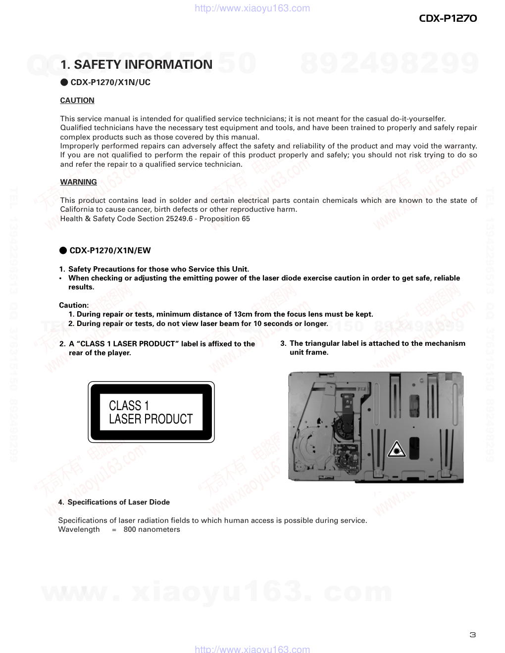
- CDX-P1270/X1N/EW
1. Safety Precautions for those who Service this Unit.
•
When checking or adjusting the emitting power of the laser diode exercise caution in order to get safe, reliable
results.
Caution:
1. During repair or tests, minimum distance of 13cm from the focus lens must be kept.
2. During repair or tests, do not view laser beam for 10 seconds or longer.
2. A “CLASS 1 LASER PRODUCT” label is affixed to the
rear of the player.
3. The triangular label is attached to the mechanism
unit frame.
CLASS 1
LASER PRODUCT
4. Specifications of Laser Diode
Specifications of laser radiation fields to which human access is possible during service.
Wavelength
=
800 nanometers
1. SAFETY INFORMATION
- CDX-P1270/X1N/UC
CAUTION
This service manual is intended for qualified service technicians; it is not meant for the casual do-it-yourselfer.
Qualified technicians have the necessary test equipment and tools, and have been trained to properly and safely repair
complex products such as those covered by this manual.
Improperly performed repairs can adversely affect the safety and reliability of the product and may void the warranty.
If you are not qualified to perform the repair of this product properly and safely; you should not risk trying to do so
and refer the repair to a qualified service technician.
WARNING
This product contains lead in solder and certain electrical parts contain chemicals which are known to the state of
California to cause cancer, birth defects or other reproductive harm.
Health & Safety Code Section 25249.6 - Proposition 65
www. xiaoyu163. com
QQ 376315150
9
9
2
8
9
4
2
9
8
TEL 13942296513
9
9
2
8
9
4
2
9
8
0
5
1
5
1
3
6
7
3
Q
Q
TEL 13942296513 QQ 376315150 892498299
TEL 13942296513 QQ 376315150 892498299
http://www.xiaoyu163.com
4
CDX-P1270
2. EXPLODED VIEWS AND PARTS LIST
2.1 PACKING
12
11
11
12
8
9
15
17
10
7
13
5
4
3
1
6
2
19
18
16
14
www. xiaoyu163. com
QQ 376315150
9
9
2
8
9
4
2
9
8
TEL 13942296513
9
9
2
8
9
4
2
9
8
0
5
1
5
1
3
6
7
3
Q
Q
TEL 13942296513 QQ 376315150 892498299
TEL 13942296513 QQ 376315150 892498299
http://www.xiaoyu163.com
5
CDX-P1270
Part No.
Mark No. Description
CDX-P1270/X1N/UC
CDX-P1270/X1N/EW
CDX-P1270/X1N/ES
1 Screw Assy
CEA1962
CEA1962
CEA1962
2 Screw
CBA1295
CBA1295
CBA1295
*
3 Polyethylene Sheet
CNM5158
CNM5158
CNM5158
4 Screw
HMB60P500FMC
HMB60P500FMC
HMB60P500FMC
5 Screw
HMF40P080FZK
HMF40P080FZK
HMF40P080FZK
6 Nut
NF60FMC
NF60FMC
NF60FMC
*
7 Polyethylene Bag
CEG1099
CEG1099
CEG1099
8 Polyethylene Bag
CEG1174
CEG1026
CEG1026
9 Carton
CHG4286
CHG4285
CHG4284
10 Contain Box
CHL4286
CHL4285
CHL4284
11 Protector
CHP2136
CHP2136
CHP2136
12 Protector
CHP2137
CHP2137
CHP2137
13 Seal
CNM5741
CNM5741
CNM5741
14-1 Owner’s Manual
CRD3351
CRD3349
CRD3348
14-2 Owner’s Manual
Not used
CRD3350
CRB1629
* 14-3 Warranty Card
Not used
CRY1157
Not used
* 14-4 Card
ARY1048
Not used
Not used
15 Magazine Assy
CXB4028
CXB6519
CXB4028
16 Angle Assy
CXB6817
CXB6817
CXB6817
17 Cord
CDE5831
CDE5830
CDE5831
*
18 Caution Card
CRP1090
CRP1090
CRP1090
*
19 Caution Card
CRP1233
CRP1233
CRP1233
- Owner’s Manual
Model
Part No.
Language
CDX-P1270/X1N/UC
CRD3351
English, French
CDX-P1270/X1N/EW
CRD3349
English, Italian, French
CRD3350
German, Dutch, Spanish
CDX-P1270/X1N/ES
CRD3348
English, Spanish, Portuguese(B), Arabic
CRB1629
Chinese
- PACKING SECTION PARTS LIST
NOTE:
- Parts marked by “*”are generally unavailable because they are not in our Master Spare Parts List.
- Screws adjacent to ∇ mark on the product are used for disassembly.
www. xiaoyu163. com
QQ 376315150
9
9
2
8
9
4
2
9
8
TEL 13942296513
9
9
2
8
9
4
2
9
8
0
5
1
5
1
3
6
7
3
Q
Q
TEL 13942296513 QQ 376315150 892498299
TEL 13942296513 QQ 376315150 892498299
http://www.xiaoyu163.com
6
CDX-P1270
2.2 EXTERIOR
www. xiaoyu163. com
QQ 376315150
9
9
2
8
9
4
2
9
8
TEL 13942296513
9
9
2
8
9
4
2
9
8
0
5
1
5
1
3
6
7
3
Q
Q
TEL 13942296513 QQ 376315150 892498299
TEL 13942296513 QQ 376315150 892498299
http://www.xiaoyu163.com
7
CDX-P1270
1 Screw
BMZ26P040FMC
2 Screw
BMZ30P040FZK
3 Button
CAC6363
4 Screw
CBA1353
5 Spring
CBH1862
6 Connector
CDE5525
7 Connector
CDE6478
8 Upper Case
CNB2614
9 Arm
CNC8058
10 Insulator
CNM6074
11 Panel
CNS5218
12 Damper
CNV6778
13 Power Unit
CWX2513
14 Screw
BMZ26P060FMC
15 Terminal(CN902)
CKF1059
16 Plug(CN901)
CKS-460
17 Connector(CN921)
CKS3407
18 Connector(CN911)
CKS3831
19 Holder
CNC8059
20 Holder
CNC8060
21 Grille Assy
CXB6831
22 Door
See Contrast table(2)
23 Door
See Contrast table(2)
24 Lower Case Unit
CXB7007
25 CD Mechanism Module(C8R2) CXK4950
26 Screw
IMS20P030FZK
27 Screw
IMS26P040FMC
28 Transistor(Q910)
2SD2396
*
29 Caution Card
CRP1233
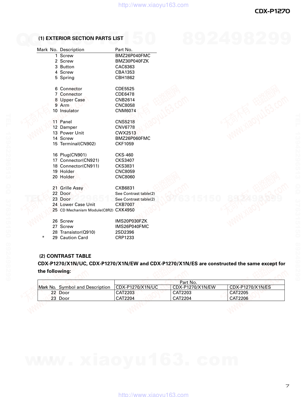
(1) EXTERIOR SECTION PARTS LIST
Mark No. Description
Part No.
Part No.
Mark No. Symbol and Description
CDX-P1270/X1N/UC
CDX-P1270/X1N/EW
CDX-P1270/X1N/ES
22 Door
CAT2203
CAT2203
CAT2205
23 Door
CAT2204
CAT2204
CAT2206
(2) CONTRAST TABLE
CDX-P1270/X1N/UC, CDX-P1270/X1N/EW and CDX-P1270/X1N/ES are constructed the same except for
the following:
www. xiaoyu163. com
QQ 376315150
9
9
2
8
9
4
2
9
8
TEL 13942296513
9
9
2
8
9
4
2
9
8
0
5
1
5
1
3
6
7
3
Q
Q
TEL 13942296513 QQ 376315150 892498299
TEL 13942296513 QQ 376315150 892498299
http://www.xiaoyu163.com
8
CDX-P1270
2.3 CD MECHANISM MODULE
www. xiaoyu163. com
QQ 376315150
9
9
2
8
9
4
2
9
8
TEL 13942296513
9
9
2
8
9
4
2
9
8
0
5
1
5
1
3
6
7
3
Q
Q
TEL 13942296513 QQ 376315150 892498299
TEL 13942296513 QQ 376315150 892498299
http://www.xiaoyu163.com
9
CDX-P1270
1 Connector
CDE6069
2 CD Core Unit
CWX2489
3 Connector(CN701)
CKS1963
4 Connector(CN101)
CKS2272
5 Screw
BMZ20P025FMC
6 Screw(M2x2.5)
CBA1037
7 Screw(M2x2.5)
CBA1041
8 Screw(M2x2)
CBA1176
9 Screw(M2x4)
CBA1362
10 Screw(M2x1.4)
CBA1387
11 Screw(M2x2.5)
CBA1493
12 Screw(M2x1.6)
CBA1476
13 Screw(M2x3)
CBA1486
14 Washer
CBF1038
15 Spring
CBH2374
16 Spring
CBH2172
17 Spring
CBH2173
18 Spring
CBH2174
19 Spring
CBH2175
20 Spring
CBH2177
21 Spring
CBH2178
22 Spring
CBH2179
23 Spring
CBL1390
24 Spring
CBL1393
25 Spring
CBL1404
26 Short Pin
CBL1239
27 Volume(VR801)
CCW1024
28 Screw(M2x1.5)
CBA1491
29 Shaft
CLA3894
30 Arm
CNC8482
31 Lever
CNC7905
32 Lever
CNC7906
33 Arm
CNC7908
34 Arm
CNC7909
35 Holder
CNC7911
36 Holder
CNC7912
37 Lever
CNC7919
38 Stopper
CNC7920
39 Frame
CNC7921
40 Lever
CNC7922
41 Bracket
CNC7923
42 Lever
CNC7924
43 Frame
CNC7927
44 Frame
CNC7928
45 Bracket
CNC8355
46 Plate
CNC8375
47 Cover
CNC8434
48 Sheet
CNM6009
49 Spacer
CNM6428
50 Sheet
CNM6296
51 PCB
CNP5227
52 PCB
CNP5228
53 Ball
CNR1189
54 Gear
CNR1531
55 Belt
CNT1086
56 Gear
CNV5472
57 Gear
CNV5473
58 Rail
CNV5920
59 Lever
CNV6091
60 Gear
CNV5477
61 Arm
CNV5478
62 Holder
CNV5480
63 Guide
CNV5921
64 Guide
CNV5922
65 Holder
CNV5483
66 Holder
CNV5484
67 Clamper
CNV5485
68 Gear
CNV5486
69 Gear
CNV5562
70 Holder
CNV5563
71 Stopper
CNV5564
72 Lighting Conductor
CNV5785
73 Mechanism PCB
CWX2303
74 Connector(CN801)
CKS1965
75 Connector(CN802)
CKS3486
76 Damper Unit
CXA7159
77 Chassis Unit
CXB4463
78 •••••
79 Chassis Unit
CXB4461
80 Arm Unit
CXB2855
81 Screw Unit
CXB4464
82 •••••
83 Frame Unit
CXB4427
84 Magazine Holder Unit
CXB4460
85 Motor Unit(M851)(SPINDLE) CXB3003
86 Motor Unit(M854)(CARRIAGE)
CXB3004
87 Screw
JFZ20P025FMC
88 Motor Unit(M853)(TRAY) CXB4421
89 Screw
JFZ20P025FMC
90 Motor Unit(M852)(ELV)
CXB3006
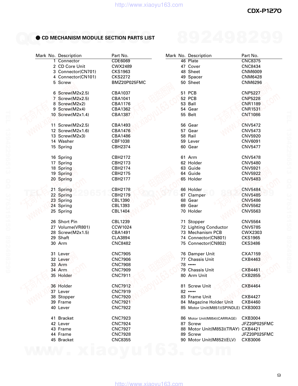
Mark No. Description
Part No.
Mark No. Description
Part No.
- CD MECHANISM MODULE SECTION PARTS LIST
www. xiaoyu163. com
QQ 376315150
9
9
2
8
9
4
2
9
8
TEL 13942296513
9
9
2
8
9
4
2
9
8
0
5
1
5
1
3
6
7
3
Q
Q
TEL 13942296513 QQ 376315150 892498299
TEL 13942296513 QQ 376315150 892498299
http://www.xiaoyu163.com
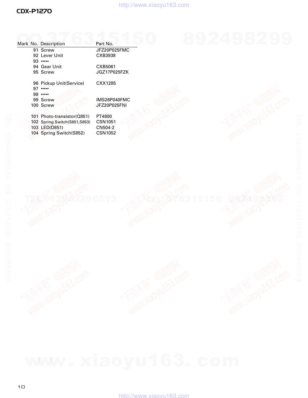
10
CDX-P1270
91 Screw
JFZ20P025FMC
92 Lever Unit
CXB3938
93 •••••
94 Gear Unit
CXB5061
95 Screw
JGZ17P025FZK
96 Pickup Unit(Service)
CXX1285
97 •••••
98 •••••
99 Screw
IMS26P040FMC
100 Screw
JFZ20P025FNI
101 Photo-transistor(Q851)
PT4800
102 Spring Switch(S851,S853)
CSN1051
103 LED(D851)
CN504-2
104 Spring Switch(S852)
CSN1052
Mark No. Description
Part No.
www. xiaoyu163. com
QQ 376315150
9
9
2
8
9
4
2
9
8
TEL 13942296513
9
9
2
8
9
4
2
9
8
0
5
1
5
1
3
6
7
3
Q
Q
TEL 13942296513 QQ 376315150 892498299
TEL 13942296513 QQ 376315150 892498299
http://www.xiaoyu163.com
11
CDX-P1270
2.4 MAGAZINE ASSY
1 Magazine Assy(UC,ES)
CXB4028
Magazine Assy(EW)
CXB6519
2 Tray
CNV5341
3 Label(UC,ES)
CRW1419
Label(EW)
CRW1416
- MAGAZINE ASSY SECTION PARTS LIST
Mark No. Description
Part No.
www. xiaoyu163. com
QQ 376315150
9
9
2
8
9
4
2
9
8
TEL 13942296513
9
9
2
8
9
4
2
9
8
0
5
1
5
1
3
6
7
3
Q
Q
TEL 13942296513 QQ 376315150 892498299
TEL 13942296513 QQ 376315150 892498299
http://www.xiaoyu163.com
PICKUP UNIT (SERVICE) (P8)
MECHANISM
PCB
HOLOGRAM
UNIT
FOCUS ACT.
TRACKING ACT.
FO+
14
9
98
39
AC/F/E/BD
FD/TD/SD/MD
I13/I04/I02
97
11
16
15
17
18
3
5
10
12
DISC
TRP
DSP
DISC
TRP
DSP
92
95
91
LD(–)
LASER
DIODE
CARRIAGE
MOTOR
MONITOR
DIODE
MD
TO+
+5V
M
SPINDLE
MOTOR
M
TRY
MOTOR
HOME SW
TRPSW
DSPSW
VR802
EJECT SW
MAG SW
M
ELV
MOTOR
M
17
12
27
16
15
11
8
9
2
1
4
3
7
5
10
Q101
Q701
VD
PD
LIMIT
xtal
XTAL
L_OUT
LD
VREF
adena
cs
23
16
24
IPIN
IPOUT
IPPW
POWER
XIN
XOUT
13
15
98
asens
bsens
reset
CDMUTE
ELVREF
CONT
ELVPVO
ejsw
mag
disk
TRP
DSP
11
94
93
74
75
3
X202
16.93MHz
X701
10.00MHz
IC 301
BA5986FM
IC 302
LB1836M
VDD
IC 701
PD5638A
A CD CORE UNIT
Q851
D851
D SWITCH PCB
E MOTOR PCB
C
S853
S801
S803
V
EVREF
GND
EPVO
L
4
3
7
5
11
8
9
2
1
10
17
12
27
16
15
5
15
4
3
4CH SERVO DRIVER
MOTOR DRIVER
SYSTEM
CONTROLLER
CN101
CN801
CN802
S852
S851
RF AMP, SERVO, DSP, DAC
IC 201
UPD63711GC
12
CDX-P1270
1
2
3
4
1
2
3
4
D
C
B
A
3. BLOCK DIAGRAM AND SCHEMATIC DIAGRAM
3.1 BLOCK DIAGRAM
www. xiaoyu163. com
QQ 376315150
9
9
2
8
9
4
2
9
8
TEL 13942296513
9
9
2
8
9
4
2
9
8
0
5
1
5
1
3
6
7
3
Q
Q
TEL 13942296513 QQ 376315150 892498299
TEL 13942296513 QQ 376315150 892498299
http://www.xiaoyu163.com
8
12
13
VD
5V
cs
IPIN
IPOUT
IPPW
POWER
48
4
2
1
2
1
30
22
10
BUSP
15
CDMUTE
LOUT
BUSM
asens
bsens
reset
9
BATT
+B
BSENIN
ASENB
5
18
10
11
14
19
9
SVC
2
5
6
12
7
4
3
1
RESET SW
5V REGULATOR
29
CDMUTE 76
8
5
6
20
ELVPVO
IC 202
BA05FP
Q771
Q770
VDD
IC 705
TC7SH32F
IC 702
LC35256FT-70U
SRAM
IC 703
HA12187FP
IP-BUS DRIVER
IC 704
PAJ002A
CN701
16
B POWER UNIT
10
7
1
Q942
Q911
BUP
Q941
BUP
BUP
BUP
Q910
LOUT
3 CDMUTE
6 BP
BUSP
LCH
5
BUSM
8
ASENB
5 BM
7 ASNB
4 SVC
1
VD
POWER
VD
VD
VD
POWER
9 +B
13 BSENIN
CN911
IP-BUS OUT
CN921
L901
BUP
GND
BATT.
GND
3
2
1
CN901
FUSE
2A
10
8
2
17
16
Q912
S802
VR801
EPVO
LINEAR POSITION SENSOR
ER
1
2
3
CN902
13
CDX-P1270
5
6
7
8
5
6
7
8
D
C
B
A
www. xiaoyu163. com
QQ 376315150
9
9
2
8
9
4
2
9
8
TEL 13942296513
9
9
2
8
9
4
2
9
8
0
5
1
5
1
3
6
7
3
Q
Q
TEL 13942296513 QQ 376315150 892498299
TEL 13942296513 QQ 376315150 892498299
http://www.xiaoyu163.com
14
CDX-P1270
1
2
3
4
1
2
3
4
D
C
B
A
3.2 CD MECHANISM MODULE
Note: When ordering service parts, be sure to refer to “EXPLODED VIEWS AND PARTS LIST” or “ELECTRICAL
PARTS LIST”.
680Ω(B)
10kΩ(B)
1
12
6
13
10
4
8
VR801 CCW1024
LINEAR POSITION SENSOR
M852
CXB3006
RF AMP, SE
MOTO
4CH SER
CN801
CN802
M853
CXB4421
M851
CXB3003
M854
CXB3004
CSN1052
CSN1051
CSN1051
CN504-2
PT4800
PICKUP UNIT(SERVICE)
CXX1285
C
MECHANISM
PCB
SWITCH PCB
D
MOTOR PCB
E
CCP1337
A1/2 C D E
www. xiaoyu163. com
QQ 376315150
9
9
2
8
9
4
2
9
8
TEL 13942296513
9
9
2
8
9
4
2
9
8
0
5
1
5
1
3
6
7
3
Q
Q
TEL 13942296513 QQ 376315150 892498299
TEL 13942296513 QQ 376315150 892498299
http://www.xiaoyu163.com
15
CDX-P1270
5
6
7
8
5
6
7
8
D
C
B
A
18
7
2
5
19
20
15
17
16
21
3
9
11
10
MP, SERVO, DSP, DAC
MOTOR DRIVER
H SERVO DRIVER
CD CORE UNIT
A
A 2/2
Decimal points for resistor
and capacitor fixed values
are expressed as :
2.2 2R2
0.022 R022
←
←
The > mark found on some component parts indicates
the importance of the safety factor of the part.
Therefore, when replacing, be sure to use parts of
identical designation.
Symbol indicates a resistor.
No differentiation is made between chip resistors and
discrete resistors.
NOTE :
Symbol indicates a capacitor.
No differentiation is made between chip capacitors and
discrete capacitors.
A1/2
www. xiaoyu163. com
QQ 376315150
9
9
2
8
9
4
2
9
8
TEL 13942296513
9
9
2
8
9
4
2
9
8
0
5
1
5
1
3
6
7
3
Q
Q
TEL 13942296513 QQ 376315150 892498299
TEL 13942296513 QQ 376315150 892498299
http://www.xiaoyu163.com
16
CDX-P1270
1
2
3
4
1
2
3
4
D
C
B
A
SYSTEM CONTROLLER
A 1/2
A2/2
www. xiaoyu163. com
QQ 376315150
9
9
2
8
9
4
2
9
8
TEL 13942296513
9
9
2
8
9
4
2
9
8
0
5
1
5
1
3
6
7
3
Q
Q
TEL 13942296513 QQ 376315150 892498299
TEL 13942296513 QQ 376315150 892498299
http://www.xiaoyu163.com
17
CDX-P1270
5
6
7
8
5
6
7
8
D
C
B
A
SRAM
IP-BUS DRIVER
B CN911
A2/2
www. xiaoyu163. com
QQ 376315150
9
9
2
8
9
4
2
9
8
TEL 13942296513
9
9
2
8
9
4
2
9
8
0
5
1
5
1
3
6
7
3
Q
Q
TEL 13942296513 QQ 376315150 892498299
TEL 13942296513 QQ 376315150 892498299
http://www.xiaoyu163.com
18
CDX-P1270
1 RFI
0.5V/div. 0.5µs/div.
Normal mode: play
1 CH1: RFI
1V/div.
2 CH2: MIRR
5V/div.
Test mode: Tracking open
0.5ms/div.
1 CH1: RFI
1V/div.
2 CH2: MIRR
5V/div.
Normal mode: The defect part
passes 800µm
0.5ms/div.
3 CH1: FD
0.5V/div.
4 CH2: FOR
2V/div.
Test mode: No disc, Focus close
0.2s/div.
3 CH1: FD
0.5V/div.
5 CH2: FOK
2V/div.
Normal mode: Focus close
0.2s/div.
6 CH1: FE
0.5V/div.
7 CH2: XSI
2V/div.
Normal mode: Focus close
1ms/div.
REFO →
8 CH1: TE
0.5V/div.
9 CH2: TD
0.5V/div.
Test mode: 32 tracks jump (REV)
0.5ms/div.
8 CH1: TE
0.5V/div.
9 CH2: TD
0.5V/div.
Test mode: Single jump (REV)
0.5ms/div.
8 CH1: TE
0.5V/div.
9 CH2: TD
0.5V/div.
Test mode: 100 tracks jump (REV)
5ms/div.
6 CH1: FE
0.1V/div.
3 CH2: FD
0.2V/div.
Normal mode: Play
20ms/div.
3 CH1: FD
0.5V/div.
0 CH2: MD
1V/div.
Normal mode: Focus close (12cm)
0.5s/div.
3 CH1: FD
0.5V/div.
0 CH2: MD
1V/div.
Normal mode: Focus close (8cm)
0.5s/div.
REFO →
REFO →
REFO →
REFO →
REFO →
REFO →
GND →
REFO →
REFO →
REFO →
REFO →
REFO →
REFO →
REFO →
REFO →
REFO →
REFO →
REFO →
REFO →
- Waveforms
Note:1. The encircled numbers denote measuring pointes in the circuit diagram.
2. Reference voltage
REFO:2.5V
REFO →
REFO →
REFO →
REFO →
www. xiaoyu163. com
QQ 376315150
9
9
2
8
9
4
2
9
8
TEL 13942296513
9
9
2
8
9
4
2
9
8
0
5
1
5
1
3
6
7
3
Q
Q
TEL 13942296513 QQ 376315150 892498299
TEL 13942296513 QQ 376315150 892498299
http://www.xiaoyu163.com
19
CDX-P1270
8 CH1: TE
0.2V/div.
9 CH2: TD
0.2V/div.
Normal mode: play
8 CH1: TE
0.5V/div.
! CH2: SD
0.5V/div.
TEST mode:100Tracks jump(FWD)
5ms/div.
0 MD
0.5V/div.
0.1s/div.
Normal mode: Play (12cm)
0 MD
1V/div.
10ms/div.
Long Search (12cm)
@ EFM
1V/div.
5µs/div.
Normal mode: Play
8 CH1: TE
1V/div.
# CH2: TEC
1V/div.
Test mode: Focus close
Tracking open
2ms/div.
8 CH1: TE
0.5V/div.
6 CH2: FE
0.5V/div.
Normal mode: AGC after focus close
0.2s/div.
20ms/div.
% SCKO
2V/div.
1µs/div.
Normal mode: Play
^ DOUT
2V/div.
10µs/div.
Normal mode: Play
& LRCK
2V/div.
20µs/div.
Normal mode: Play
* VD
5V/div.
50ms/div.
Normal mode: No disc
GND →
REFO →
REFO →
GND →
REFO →
REFO →
REFO →
REFO →
REFO →
REFO →
REFO →
REFO →
REFO →
GND →
REFO →
GND →
REFO →
GND →
REFO →
www. xiaoyu163. com
QQ 376315150
9
9
2
8
9
4
2
9
8
TEL 13942296513
9
9
2
8
9
4
2
9
8
0
5
1
5
1
3
6
7
3
Q
Q
TEL 13942296513 QQ 376315150 892498299
TEL 13942296513 QQ 376315150 892498299
http://www.xiaoyu163.com
20
CDX-P1270
( CH1: R OUT
2V/div.
) CH2: L OUT
2V/div.
Normal mode: Play (1kHz 0dB)
6 CH1: FE
0.2V/div.
3 CH2: FD
0.5V/div.
Normal mode: During AGC
1ms/div.
8 CH1: TE
0.2V/div.
9 CH2: TD
0.5V/div.
Normal mode: During AGC
1 CH1: RFI
1V/div.
⁄ CH2: HOLD
5V/div.
Normal mode: The defect part passes
800µm(B.D)
500µs/div.
1ms/div.
0.5ms/div.
3 CH1: FD
1V/div.
⁄ CH2: HOLD
5V/div.
Normal mode: The defect part passes
800µm(B.D)
0.5ms/div.
9 CH1: TD
0.1V/div.
⁄ CH2: HOLD
5V/div.
Normal mode: The defect part passes
800µm(B.D)
0.5ms/div.
REFO →
REFO →
REFO →
REFO →
REFO →
REFO →
REFO →
REFO →
REFO →
REFO →
REFO →
REFO →
www. xiaoyu163. com
QQ 376315150
9
9
2
8
9
4
2
9
8
TEL 13942296513
9
9
2
8
9
4
2
9
8
0
5
1
5
1
3
6
7
3
Q
Q
TEL 13942296513 QQ 376315150 892498299
TEL 13942296513 QQ 376315150 892498299
http://www.xiaoyu163.com
8V REG.
MUTE
CN701
B POWER UNIT
A 2/2
21
CDX-P1270
1
2
3
4
1
2
3
4
D
C
B
A
B
3.3 POWER UNIT
UC, ES : CEK1018
EW : CEK1033
www. xiaoyu163. com
QQ 376315150
9
9
2
8
9
4
2
9
8
TEL 13942296513
9
9
2
8
9
4
2
9
8
0
5
1
5
1
3
6
7
3
Q
Q
TEL 13942296513 QQ 376315150 892498299
TEL 13942296513 QQ 376315150 892498299
http://www.xiaoyu163.com
E
E
IC, Q
ADJ
M
M852
ELV
B CN911
C CN801
E
F
REFO
EREF
EPVO
1
25
26
50 51
75
76
100
22
CDX-P1270
1
2
3
4
1
2
3
4
D
C
B
A
4. PCB CONNECTION DIAGRAM
4.1 CD CORE UNIT
SIDE A
CD CORE UNIT
A
NOTE FOR PCB DIAGRAMS
1. The parts mounted on this PCB
include all necessary parts for
several destination.
For further information for
respective destinations, be sure
to check with the schematic dia-
gram.
Capacitor
Connector
P.C.Board
Chip Part
SIDE A
SIDE B
2. Viewpoint of PCB diagrams
A
www. xiaoyu163. com
QQ 376315150
9
9
2
8
9
4
2
9
8
TEL 13942296513
9
9
2
8
9
4
2
9
8
0
5
1
5
1
3
6
7
3
Q
Q
TEL 13942296513 QQ 376315150 892498299
TEL 13942296513 QQ 376315150 892498299
http://www.xiaoyu163.com
23
CDX-P1270
1
2
3
4
1
2
3
4
D
C
B
A
E
E
E
IC, Q
RESET
EJECT
MAG
SIDE B
CD CORE UNIT
A
A
www. xiaoyu163. com
QQ 376315150
9
9
2
8
9
4
2
9
8
TEL 13942296513
9
9
2
8
9
4
2
9
8
0
5
1
5
1
3
6
7
3
Q
Q
TEL 13942296513 QQ 376315150 892498299
TEL 13942296513 QQ 376315150 892498299
http://www.xiaoyu163.com
24
CDX-P1270
1
2
3
4
1
2
3
4
D
C
B
A
B
SIDE A
4.2 POWER UNIT
A CN701
IP-BUS
POWER UNIT
B
CORD
www. xiaoyu163. com
QQ 376315150
9
9
2
8
9
4
2
9
8
TEL 13942296513
9
9
2
8
9
4
2
9
8
0
5
1
5
1
3
6
7
3
Q
Q
TEL 13942296513 QQ 376315150 892498299
TEL 13942296513 QQ 376315150 892498299
http://www.xiaoyu163.com
25
CDX-P1270
1
2
3
4
1
2
3
4
D
C
B
A
B
SIDE B
POWER UNIT
B
www. xiaoyu163. com
QQ 376315150
9
9
2
8
9
4
2
9
8
TEL 13942296513
9
9
2
8
9
4
2
9
8
0
5
1
5
1
3
6
7
3
Q
Q
TEL 13942296513 QQ 376315150 892498299
TEL 13942296513 QQ 376315150 892498299
http://www.xiaoyu163.com
26
CDX-P1270
1
2
3
4
1
2
3
4
D
C
B
A
4.4 SWITCH PCB
SWITCH PCB
D
C
4.3 MECHANISM PCB
A
CN101
E
D
MECHANISM PCB
C
M
M854
CRG
M
M851
SPDL
HOME
TRP
DSP
D851
PICKUP UNIT
(SERVICE)
C D
www. xiaoyu163. com
QQ 376315150
9
9
2
8
9
4
2
9
8
TEL 13942296513
9
9
2
8
9
4
2
9
8
0
5
1
5
1
3
6
7
3
Q
Q
TEL 13942296513 QQ 376315150 892498299
TEL 13942296513 QQ 376315150 892498299
http://www.xiaoyu163.com
27
CDX-P1270
1
2
3
4
1
2
3
4
D
C
B
A
4.5 MOTOR PCB
MOTOR PCB
E
E
C
www. xiaoyu163. com
QQ 376315150
9
9
2
8
9
4
2
9
8
TEL 13942296513
9
9
2
8
9
4
2
9
8
0
5
1
5
1
3
6
7
3
Q
Q
TEL 13942296513 QQ 376315150 892498299
TEL 13942296513 QQ 376315150 892498299
http://www.xiaoyu163.com
28
CDX-P1270
Unit Number
: CWX2489
Unit Name
: CD Core Unit
MISCELLANEOUS
IC
201
IC
UPD63711GC
IC
202
IC
BA05FP
IC
301
IC
BA5986FM
IC
302
IC
LB1836M
IC
701
IC
PD5638A
IC
702
IC
LC35256FT-70U
IC
703
IC
HA12187FP
IC
704
IC
PAJ002A
IC
705
IC
TC7SH32F
Q
101
Transistor
2SB1132
Q
701
Transistor
DTA144EK
Q
770
Transistor
2SB1184F5
Q
771
Transistor
2SC2412K
D
730
Diode
1SS356
D
770
Diode
1SS355
X
202
Ceramic Resonator 16.93MHz
CSS1536
X
701
Radiator 10.00MHz
CSS1428
S
801
Push Switch(EJECT)
CSG1139
S
802
Push Switch(RESET)
CSG1139
S
803
Spring Switch(MAG)
CSN1044
VR
802
Semi-fixed 680Ω(B)
CCP1337
RESISTORS
R
101
RS1/8S120J
R
102
RS1/8S100J
R
103
RS1/16S222J
R
201
RS1/16S104J
R
202
RS1/16S0R0J
R
205
RS1/16S103J
R
206
RS1/16S393J
R
207
RS1/16S182J
R
213
RS1/16S103J
R
214
RS1/16S103J
R
215
RS1/16S123J
R
231
RS1/16S821J
R
232
RS1/16S821J
R
253
RS1/16S681J
R
254
RS1/16S681J
R
256
RS1/16S681J
R
257
RS1/16S681J
R
258
RS1/16S681J
R
259
RS1/16S102J
R
260
RS1/16S681J
R
298
RS1/16S681J
R
301
RS1/16S103J
R
302
RS1/16S153J
R
303
RS1/16S103J
R
304
RS1/16S103J
R
305
RS1/16S103J
R
306
RS1/16S752J
R
307
RS1/16S103J
R
308
RS1/16S752J
R
309
RAB4C332J
R
311
RS1/16S102J
R
701
RS1/16S681J
R
702
RS1/16S102J
R
703
RS1/16S222J
R
704
RS1/16S104J
R
705
RS1/16S104J
R
706
RS1/16S222J
R
707
RS1/16S104J
R
708
RS1/16S0R0J
R
715
RS1/16S473J
R
716
RS1/16S103J
R
717
RS1/16S473J
R
718
RS1/16S681J
R
720
RS1/16S104J
R
721
RS1/16S222J
R
722
RS1/16S222J
R
724
RS1/16S681J
R
725
RS1/16S222J
R
726
RS1/16S104J
R
727
RS1/16S513J
R
729
RS1/16S473J
R
730
RS1/16S473J
R
731
RS1/16S222J
R
732
RS1/16S683J
R
733
RS1/16S222J
R
734
RS1/16S473J
R
735
RS1/16S222J
R
736
RS1/16S103J
R
737
RS1/16S433J
R
738
RS1/16S104J
R
739
RS1/8S1R0J
R
740
RS1/8S2R0J
R
741
RS1/16S102J
R
742
RS1/16S104J
R
743
RS1/16S104J
R
744
RS1/16S223J
R
745
RS1/16S104J
R
747
RS1/16S472J
R
750
RAB4C473J
R
751
RAB4C473J
R
752
RS1/16S3602D
R
753
RS1/16S6801D
R
754
RS1/16S221J
R
755
RS1/16S104J
R
756
RS1/16S221J
R
759
RS1/16S472J
R
760
RS1/16S104J
R
761
RS1/16S104J
R
764
RS1/16S473J
R
768
RS1/8S220J
5. ELECTRICAL PARTS LIST
NOTE:
- Parts whose parts numbers are omitted are subject to being not supplied.
- The part numbers shown below indicate chip components.
Chip Resistor
RS1/_S___J,RS1/__S___J
Chip Capacitor (except for CQS.....)
CKS....., CCS....., CSZS.....
=====Circuit Symbol and No.===Part Name
Part No.
---
------
------------------------------------------
-------------------------
=====Circuit Symbol and No.===Part Name
Part No.
---
------
------------------------------------------
-------------------------
A
www. xiaoyu163. com
QQ 376315150
9
9
2
8
9
4
2
9
8
TEL 13942296513
9
9
2
8
9
4
2
9
8
0
5
1
5
1
3
6
7
3
Q
Q
TEL 13942296513 QQ 376315150 892498299
TEL 13942296513 QQ 376315150 892498299
http://www.xiaoyu163.com
29
CDX-P1270
R
801
RS1/10S221J
R
802
RS1/10S271J
R
804
RS1/16S512J
R
805
RS1/16S432J
R
806
RS1/16S102J
CAPACITORS
C
101
CKSRYB102K50
C
102
CKSRYB104K16
C
103
CEV101M6R3
C
104
CEV470M6R3
C
105
CKSRYB224K16
C
106
CKSRYB224K16
C
107
CKSRYB224K16
C
201
CKSRYB104K16
C
202
CEV101M6R3
C
203
CKSRYB104K16
C
204
CKSRYB332K50
C
205
CKSRYB104K16
C
206
CKSRYB392K50
C
207
CKSRYB104K16
C
208
CCSRCH270J50
C
209
CCSRCJ3R0C50
C
210
CCSRCH181J50
C
211
CCSRCH510J50
C
212
CKSRYB682K50
C
213
CKSRYB104K16
C
214
CKSRYB104K16
C
215
CKSRYB104K16
C
216
CKSRYB104K16
C
217
CKSRYB104K16
C
218
CKSRYB104K16
C
219
CKSQYB334K16
C
220
CKSRYB104K16
C
234
CKSRYB224K16
C
235
CEV220M6R3
C
236
CCSQSL152J50
C
237
CCSQSL152J50
C
238
CKSRYB103K25
C
253
CKSRYB471K50
C
271
CEV101M6R3
C
272
10µF/16V
CCH1399
C
273
CKSRYB224K16
C
301
CEV101M10
C
302
CKSRYB224K16
C
701
CKSRYB104K16
C
702
CKSRYB473K16
C
703
CKSRYB473K16
C
707
CKSRYB103K25
C
708
CKSRYB104K16
C
710
CKSRYB103K25
C
711
CKSRYB102K50
C
712
CKSRYB102K50
C
714
CKSRYB104K16
C
715
22µF/10V
CCH1403
C
717
CKSRYB103K25
C
718
CKSRYB103K25
C
719
CKSRYB102K50
C
720
CKSRYB102K50
C
721
CKSRYB103K25
C
722
CKSRYB103K25
C
724
CKSRYB471K50
C
801
CKSRYB103K25
C
802
CKSRYB104K16
C
803
CKSRYB103K25
Unit Number : CWX2513
Unit Name
: Power Unit
MISCELLANEOUS
Q
910
Transistor
2SD2396
Q
911
Transistor
IMD2A
Q
912
Transistor
IMX1
Q
941
Transistor
FMG12
Q
942
Transistor
IMD2A
D
901
Diode
1SR139-400
D
902
Diode
1SR139-400
D
910
Diode
HZS6L(B1)
D
941
Diode
MA152WA
L
901
Choke Coil 1mH
CTH1047
RESISTORS
R
901
RS1/16S204J
R
902
RS1/16S104J
R
903
RS1/4SA101J
R
910
RS1/8S431J
R
911
RS1/16S681J
R
912
RS1/8S101J
R
913
RS1/16S512J
R
914
RS1/16S132J
R
915
RD1/4PU151J
R
921
RS1/16S101J
R
922
RS1/16S101J
R
923
RS1/16S102J
R
924
RS1/16S473J
R
941
RS1/16S181J
R
942
RS1/16S181J
R
943
RS1/16S472J
R
944
RS1/16S472J
R
945
RS1/10S472J
CAPACITORS
C
901
CKSRYB224K16
C
902
CEAT471M16
C
903
CKSRYB223K25
C
904
CEAT471M16
C
906
0.1F/5.5V
CCL1054
C
907
CKSRYB224K16
C
910
CKSRYB103K50
C
911
CKSRYB103K50
C
912
CEJA220M10
C
913
CKSRYB103K50
C
920
CCSRCH471J50
C
921
CCSRCH471J50
C
941
CEJA330M10
C
942
CEJA330M10
C
943
CCSRCH471J50
C
944
CCSRCH471J50
Unit Number :
Unit Name
: Mechanism PCB
Q
851
Photo-transistor
PT4800
S
853
Spring Switch(HOME)
CSN1051
Unit Number :
Unit Name
: Switch PCB
D
851
LED
CN504-2
S
851
Spring Switch(TAP)
CSN1051
S
852
Spring Switch(DSP)
CSN1052
=====Circuit Symbol and No.===Part Name
Part No.
---
------
------------------------------------------
-------------------------
=====Circuit Symbol and No.===Part Name
Part No.
---
------
------------------------------------------
-------------------------
B
C
D
www. xiaoyu163. com
QQ 376315150
9
9
2
8
9
4
2
9
8
TEL 13942296513
9
9
2
8
9
4
2
9
8
0
5
1
5
1
3
6
7
3
Q
Q
TEL 13942296513 QQ 376315150 892498299
TEL 13942296513 QQ 376315150 892498299
http://www.xiaoyu163.com
30
CDX-P1270
Unit Number
:
Unit Name
: Motor PCB
M
853
Motor Unit(TRAY)
CXB4421
Miscellaneous Parts List
Pickup Unit(P8)(Service)
CXX1285
M
851
Motor Unit(SPINDLE)
CXB3003
M
852
Motor Unit(ELV)
CXB3006
M
854
Motor Unit(CARRIAGE)
CXB3004
VR
801
Volume 10kΩ(B)
CCW1024
=====Circuit Symbol and No.===Part Name
Part No.
---
------
------------------------------------------
-------------------------
E
www. xiaoyu163. com
QQ 376315150
9
9
2
8
9
4
2
9
8
TEL 13942296513
9
9
2
8
9
4
2
9
8
0
5
1
5
1
3
6
7
3
Q
Q
TEL 13942296513 QQ 376315150 892498299
TEL 13942296513 QQ 376315150 892498299
http://www.xiaoyu163.com
31
CDX-P1270
- Precautions
• This unit uses a single power supply (+5V) for the reg-
ulator. The signal reference potential, therefore, is
connected to REFO(approx. 2.5V) instead of GND.
If REFO and GND are connected to each other by mis-
take during adjustments, not only will it be impossi-
ble to measure the potential correctly, but the servo
will malfunction and a severe shock will be applied to
the pick-up. To avoid this, take special note of the fol-
lowing.
Do not connect the negative probe of the measuring
equipment to REFO and GND together. It is especially
important not to connect the channel 1 negative
probe of the oscilloscope to REFO with the channel 2
negative probe connected to GND.
Since the frame of the measuring instrument is usual-
ly at the same potential as the negative probe, change
the frame of the measuring instrument to floating sta-
tus.
If by accident REFO comes in contact with GND,
immediately switch the regulator or power OFF.
• Always make sure the regulator is OFF when connect-
ing and disconnecting the various filters and wiring
required for measurements.
• Before proceeding to further adjustments and mea-
surements after switching regulator ON, let the player
run for about one minute to allow the circuits to stabi-
lize.
• Since the protective systems in the unit's software are
rendered inoperative in test mode, be very careful to
avoid mechanical and /or electrical shocks to the sys-
tem when making adjustment.
• Disc detection during tray extraction and return oper-
ations is performed by means of the photo transistor
in this unit. Consequently, if the inside of the unit is
exposed to a strong light source with the outer casing
removed for repairs or adjustment, the following mal-
functions may occur:
*Even with a disc loaded, the unit detects "no disc"
and cannot start play.
*Although a 12-cm disc is loaded, the unit detects
"8cm disc" mistakenly.
When the unit malfunctions this way, either re-posi-
tion the light source, move the unit or cover the photo
transistor.
• During exchanging discs, do not press the keys for
the discs to be exchanged.
Key to adjustment text
HEAD UNIT (6 keys type)
inside (12 keys type)
BAND
BAND
TRK+/FF
TRK+/FF
TRK-/REV
TRK-/REV
7
1
8
2
9
3
10
4
11
5
12
6
DISC-
DISC-
SOURCE ON/OFF
SOURCE ON/OFF
6. ADJUSTMENT
6.1 CD ADJUSTMENT
www. xiaoyu163. com
QQ 376315150
9
9
2
8
9
4
2
9
8
TEL 13942296513
9
9
2
8
9
4
2
9
8
0
5
1
5
1
3
6
7
3
Q
Q
TEL 13942296513 QQ 376315150 892498299
TEL 13942296513 QQ 376315150 892498299
http://www.xiaoyu163.com
32
CDX-P1270
- CD Test mode
This mode is used for adjusting the CD mechanism
module of the device.
• Test mode starting procedure
Reset while pressing the 4 and 6 keys together.
• Test mode cancellation
Switch ACC, back-up OFF.
• If the 8 or 9 key is pressed while focus search is in
progress, immediately turn the power off (otherwise
the actuator may be damaged due to the lens stuck).
• Jump operation of TRs other than 100TR continues
after releasing the key. CRG move and 100TR jump
operations are brought into the “Tracking close” sta-
tus when the key is released.
• Powering Off/On resets the jump mode to “Single TR
(91)”, the RF AMP gain setting to 0 dB, and the auto-
matic adjustment value to the initial value.
• During exchanging discs, do not press the keys for
the discs to be exchanged.
• The following head units are exceptional so that their
entering ways to the test mode are different from oth-
ers.
Test mode starting procedure
Reset while pressing the 3 and 5 keys together.
KEH-P5010R/X1M/EW
KEH-4011/X1M/EE
KEH-P5011/X1M/EE
KEH-4010R/X1M/EW
KEH-P4010RB/X1M/EW
KEH-P4013R/X1M/EW
KEH-5015/X1M/ES
KEH-P4010/X1M/UC
KEH-P4015/X1M/ES
www. xiaoyu163. com
QQ 376315150
9
9
2
8
9
4
2
9
8
TEL 13942296513
9
9
2
8
9
4
2
9
8
0
5
1
5
1
3
6
7
3
Q
Q
TEL 13942296513 QQ 376315150 892498299
TEL 13942296513 QQ 376315150 892498299
http://www.xiaoyu163.com
33
CDX-P1270
Focus Close
*2
S Curve Check
01 01 01
00 00 00
(99 99 99)
Display
TYP
4
9
Reset
SOURCE
New test mode
6
TRK-
BAND
9
*2
*1
+6dB
+12dB
*4
*5
12
12
12
12
7
8
7
8
TRK+
TRK+
TRK-
06 06 06
12 12 12
Sourse CD
Single TR
9x(8x):91(81)
32TRK
92(82)
CRG Move
94(84)
100TRK
93(83)
Focus Mode
Select
Focus Close/
S Curve Check
CRG−
Auto Adjustment
Display Select
版权声明
1. 本站所有素材,仅限学习交流,仅展示部分内容,如需查看完整内容,请下载原文件。
2. 会员在本站下载的所有素材,只拥有使用权,著作权归原作者所有。
3. 所有素材,未经合法授权,请勿用于商业用途,会员不得以任何形式发布、传播、复制、转售该素材,否则一律封号处理。
4. 如果素材损害你的权益请联系客服QQ:77594475 处理。