先锋PIONEER CDX-M8086ZT音响电路原理图
 "先锋PIONEER CDX-M8086ZT音响电路原理图-0")
 "先锋PIONEER CDX-M8086ZT音响电路原理图-1")
 "先锋PIONEER CDX-M8086ZT音响电路原理图-2")
 "先锋PIONEER CDX-M8086ZT音响电路原理图-3")
 "先锋PIONEER CDX-M8086ZT音响电路原理图-4")
 "先锋PIONEER CDX-M8086ZT音响电路原理图-5")
 "先锋PIONEER CDX-M8086ZT音响电路原理图-6")
 "先锋PIONEER CDX-M8086ZT音响电路原理图-7")
 "先锋PIONEER CDX-M8086ZT音响电路原理图-8")
 "先锋PIONEER CDX-M8086ZT音响电路原理图-9")
ORDER NO.
CRT2150
Service
Manual
PUB. NO. CRT2150
Manufactured for TOYOTA
by PIONEER ELECTRONIC CORPORATION
VEHICLE
DESTINATION
PRODUCED AFTER
TOYOTA PART No.
ID No.
PIONEER MODEL No.
TOYOTA
GERMANY, FRANCE,
JANUARY 1998
86270-60030
CDX-M8086ZT/E
LAND CRUISER
SWITZERLAND,
CDX-M8086ZT-91/E
100 SERIES
SAUDI ARABIA, OMAN,
U.A.E, KUWAIT
LEXUS LX470
SAUDI ARABIA, OMAN,
U.A.E, KUWAIT
TOYOTA
GREAT BRITAIN,
JANUARY 1998
86270-60030
CDX-M8186ZT/WL
LAND CRUISER
AUSTRALIA,
CDX-M8186ZT-91/WL
100 SERIES
NEW ZEALAND
LEXUS LX470,
AUSTRALIA,
NEW ZEALAND
LX470
TOYOTA
LAND CRUISER
100 SERIES
AUDIO SYSTEM
DISC PLAYER ASSY
www. xiaoyu163. com
QQ 376315150
9
9
2
8
9
4
2
9
8
TEL 13942296513
9
9
2
8
9
4
2
9
8
0
5
1
5
1
3
6
7
3
Q
Q
TEL 13942296513 QQ 376315150 892498299
TEL 13942296513 QQ 376315150 892498299
http://www.xiaoyu163.com
2
CDX-M8086ZT,M8086ZT-91,M8186ZT,M8186ZT-91
- CD Player Service Precautions
1. For PU unit(CGY1036) handling,please refer to
"Disassembly"(Fig.20).
During replacement,handling precautions shall be
taken to prevent an electrostatic discharge(protection
by a short pin).
2. Be sure to turn the power off before disassembly. An
internal IC might be destroyed when a connector is
plugged or unplugged.
3. These CD players have been designed to be set
upright in a car. Therefore, when operating or adjust-
ing, set them upright.
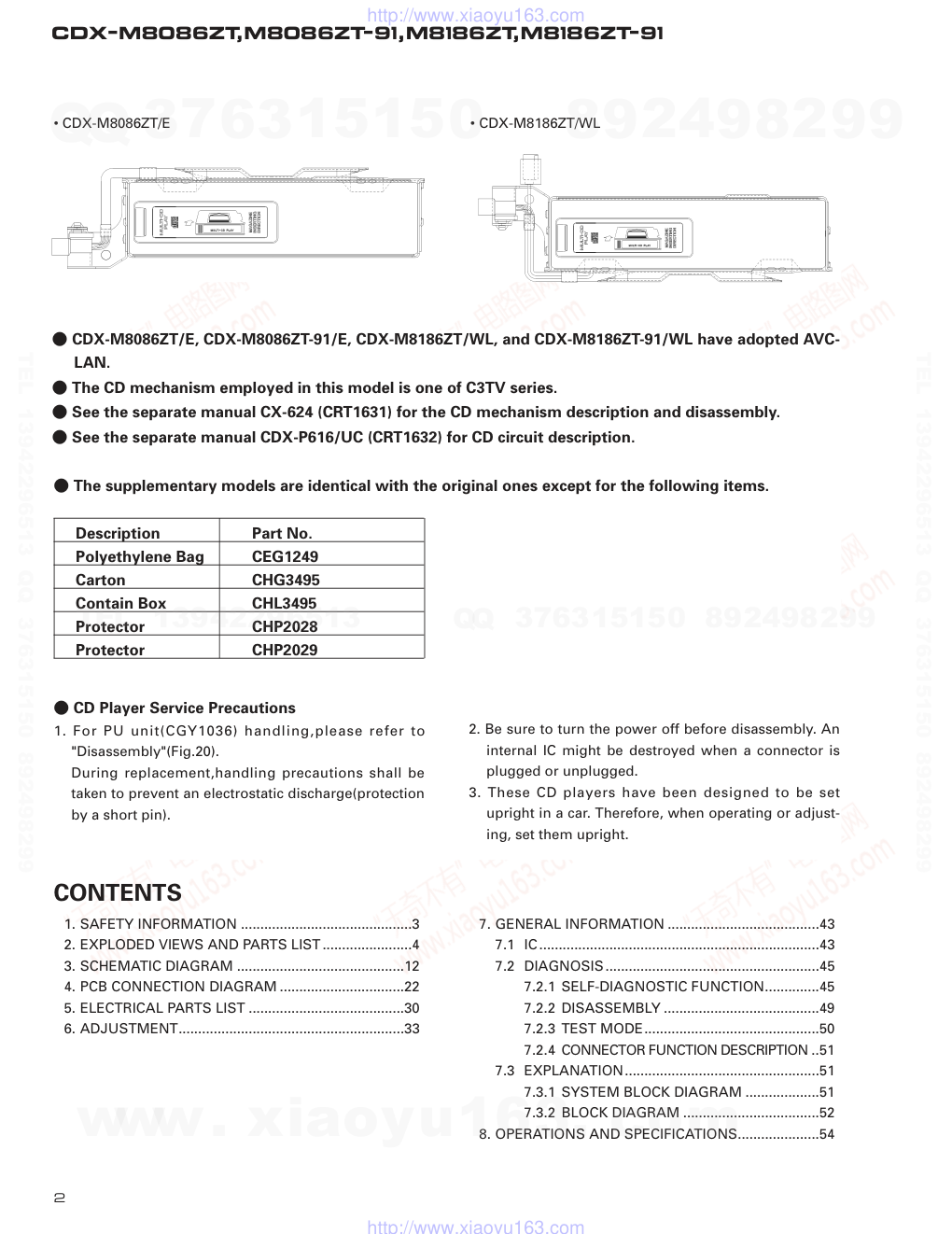
- CDX-M8086ZT/E, CDX-M8086ZT-91/E, CDX-M8186ZT/WL, and CDX-M8186ZT-91/WL have adopted AVC-
LAN.
- The CD mechanism employed in this model is one of C3TV series.
- See the separate manual CX-624 (CRT1631) for the CD mechanism description and disassembly.
- See the separate manual CDX-P616/UC (CRT1632) for CD circuit description.
• CDX-M8086ZT/E
• CDX-M8186ZT/WL
CONTENTS
1. SAFETY INFORMATION ............................................3
2. EXPLODED VIEWS AND PARTS LIST.......................4
3. SCHEMATIC DIAGRAM ...........................................12
4. PCB CONNECTION DIAGRAM ................................22
5. ELECTRICAL PARTS LIST ........................................30
6. ADJUSTMENT..........................................................33
7. GENERAL INFORMATION .......................................43
7.1 IC........................................................................43
7.2 DIAGNOSIS.......................................................45
7.2.1 SELF-DIAGNOSTIC FUNCTION..............45
7.2.2 DISASSEMBLY ........................................49
7.2.3 TEST MODE.............................................50
7.2.4 CONNECTOR FUNCTION DESCRIPTION ..51
7.3 EXPLANATION..................................................51
7.3.1 SYSTEM BLOCK DIAGRAM ...................51
7.3.2 BLOCK DIAGRAM ...................................52
8. OPERATIONS AND SPECIFICATIONS.....................54
- The supplementary models are identical with the original ones except for the following items.
Description
Part No.
Polyethylene Bag
CEG1249
Carton
CHG3495
Contain Box
CHL3495
Protector
CHP2028
Protector
CHP2029
www. xiaoyu163. com
QQ 376315150
9
9
2
8
9
4
2
9
8
TEL 13942296513
9
9
2
8
9
4
2
9
8
0
5
1
5
1
3
6
7
3
Q
Q
TEL 13942296513 QQ 376315150 892498299
TEL 13942296513 QQ 376315150 892498299
http://www.xiaoyu163.com
3
CDX-M8086ZT,M8086ZT-91,M8186ZT,M8186ZT-91
1. SAFETY INFORMATION
This service manual is intended for qualified service technicians; it is not meant for the casual do-it-yourselfer.
Qualified technicians have the necessary test equipment and tools, and have been trained to properly and safely repair
complex products such as those covered by this manual.
Improperly performed repairs can adversely affect the safety and reliability of the product and may void the warranty.
If you are not qualified to perform the repair of this product properly and safely, you should not risk trying to do so
and refer the repair to a qualified service technician.
1. Safety Precautions for those who Service this Unit.
•
Follow the adjustment steps (see pages 33 through 42)in the service manual when servicing this unit. When check-
ing or adjusting the emitting power of the laser diode exercise caution in order to get safe, reliable results.
Caution:
1. During repair or tests, minimum distance of 13cm from the focus lens must be kept.
2. During repair or tests, do not view laser beam for 10 seconds or longer.
2. A “CLASS 1 LASER PRODUCT” label is affixed to the
rear of the player.
3. The triangular label is attached to the mechanism
unit frame.
4. Specifications of Laser Diode
Specifications of laser radiation fields to which human access is possible during service.
Wavelength
=
785 nanometers
Radiant power =
69.7 microwatts(Through a circular aperture stop having a diameter of 80 millimeters)
0.55 microwatts(Through a circular aperture stop having a diameter of 7 millimeters)
www. xiaoyu163. com
QQ 376315150
9
9
2
8
9
4
2
9
8
TEL 13942296513
9
9
2
8
9
4
2
9
8
0
5
1
5
1
3
6
7
3
Q
Q
TEL 13942296513 QQ 376315150 892498299
TEL 13942296513 QQ 376315150 892498299
http://www.xiaoyu163.com
4
CDX-M8086ZT,M8086ZT-91,M8186ZT,M8186ZT-91
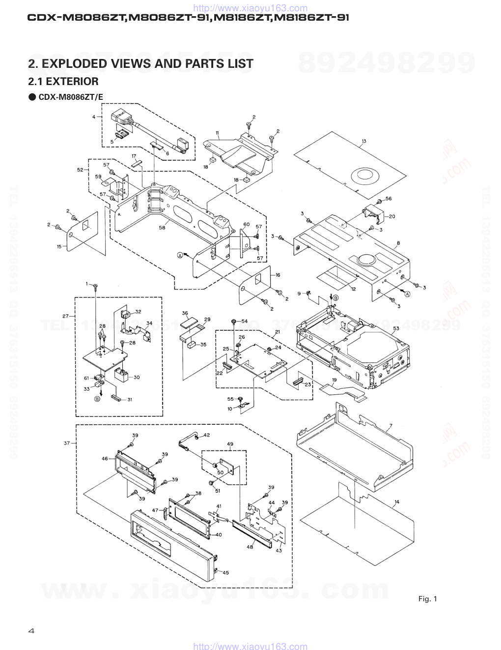
2. EXPLODED VIEWS AND PARTS LIST
2.1 EXTERIOR
- CDX-M8086ZT/E
Fig. 1
www. xiaoyu163. com
QQ 376315150
9
9
2
8
9
4
2
9
8
TEL 13942296513
9
9
2
8
9
4
2
9
8
0
5
1
5
1
3
6
7
3
Q
Q
TEL 13942296513 QQ 376315150 892498299
TEL 13942296513 QQ 376315150 892498299
http://www.xiaoyu163.com
5
CDX-M8086ZT,M8086ZT-91,M8186ZT,M8186ZT-91
1 Screw
BMZ26P080FMC
2 Screw
BMZ40P060FMC
3 Screw
BSZ30P055FMC
4 Cord
CDE5651
5 82711-2B640
CNV5293
6 82711-16270
CNV5294
7 Case
CNB1987
8 Case
CNB2015
9 Earth Plate
CNC5769
10 Earth
CNC6340
11 Bracket
CNC7164
12 Insulator
CNM4428
13 Cushion
CNM5323
14 Cushion
CNM5324
15 Cushion
CNM5328
16 Cushion
CNM5329
*
17 Corrosive Cloth
CNM5828
18 Cushion
CNM5838
19 PCB
CNP3954
20 Holder
CNV4095
21 Main Unit
CWX2123
22 Connector(CN1701)
CKS2770
23 Connector(CN1801)
CKS2779
24 Connector(CN1803)
CKS3124
25 Connector(CN1702)
CKS3125
26 Connector(CN1802)
CKS3127
27 Extension Unit
CWX2126
28 Screw
CBA1339
29 Connector
CDE5009
30 Plug(CN901)
CKM1211
31 Connector(CN903)
CKS2224
32 Connector(CN951)
CKS3359
33 Heat Sink
CNC4447
34 Holder
CNC6544
35 Spacer
CNM4821
36 Spacer
CNM4822
37 Grille Assy
CXB1309
38 Screw
BPZ20P060FMC
39 Screw
BPZ26P080FMC
40 Door
CAT1882
41 Spring
CBL1162
42 Connector
CDE5370
*
43 Holder
CNC7128
44 Earth Plate
CNC7791
*
45 Grille
CNS4517
*
46 Sub Grille
CNS4518
*
47 Handle
CNS4544
48 Rail
CNV3487
49 Grille Unit
CWM5438
50 Plug(CN906)
CKS1050
51 Screw
IMS26P050FMC
52 Bracket Unit
CXB1367
53 CD Mechanism Unit
CXK4025
54 Screw
IMS20P030FMC
55 Screw
IMS26P040FMC
56 Screw
ISS30P080FZK
57 Screw
BMZ40P060FMC
*
58 Bracket
CNC7157
*
59 Bracket
CNC7158
*
60 Bracket
CNC7339
61 Transistor(Q911)
2SB942A
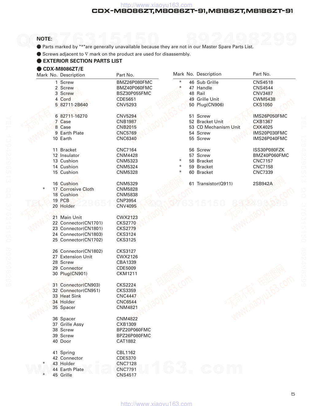
- EXTERIOR SECTION PARTS LIST
- CDX-M8086ZT/E
Mark No. Description
Part No.
Mark No. Description
Part No.
NOTE:
- Parts marked by "*"are generally unavailable because they are not in our Master Spare Parts List.
- Screws adjacent to ∇ mark on the product are used for disassembly.
www. xiaoyu163. com
QQ 376315150
9
9
2
8
9
4
2
9
8
TEL 13942296513
9
9
2
8
9
4
2
9
8
0
5
1
5
1
3
6
7
3
Q
Q
TEL 13942296513 QQ 376315150 892498299
TEL 13942296513 QQ 376315150 892498299
http://www.xiaoyu163.com
6
CDX-M8086ZT,M8086ZT-91,M8186ZT,M8186ZT-91
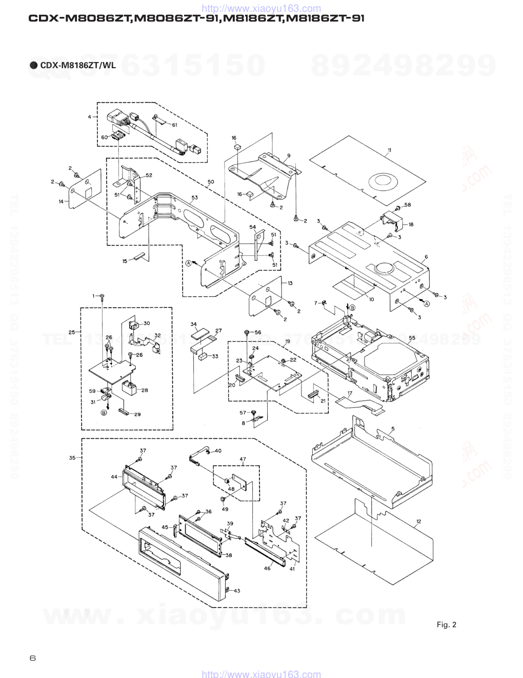
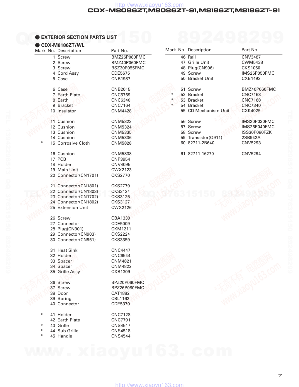
- CDX-M8186ZT/WL
Fig. 2
www. xiaoyu163. com
QQ 376315150
9
9
2
8
9
4
2
9
8
TEL 13942296513
9
9
2
8
9
4
2
9
8
0
5
1
5
1
3
6
7
3
Q
Q
TEL 13942296513 QQ 376315150 892498299
TEL 13942296513 QQ 376315150 892498299
http://www.xiaoyu163.com
7
CDX-M8086ZT,M8086ZT-91,M8186ZT,M8186ZT-91
1 Screw
BMZ26P080FMC
2 Screw
BMZ40P060FMC
3 Screw
BSZ30P055FMC
4 Cord Assy
CDE5675
5 Case
CNB1987
6 Case
CNB2015
7 Earth Plate
CNC5769
8 Earth
CNC6340
9 Bracket
CNC7164
10 Insulator
CNM4428
11 Cushion
CNM5323
12 Cushion
CNM5324
13 Cushion
CNM5335
14 Cushion
CNM5336
*
15 Corrosive Cloth
CNM5828
16 Cushion
CNM5838
17 PCB
CNP3954
18 Holder
CNV4095
19 Main Unit
CWX2123
20 Connector(CN1701)
CKS2770
21 Connector(CN1801)
CKS2779
22 Connector(CN1803)
CKS3124
23 Connector(CN1702)
CKS3125
24 Connector(CN1802)
CKS3127
25 Extension Unit
CWX2126
26 Screw
CBA1339
27 Connector
CDE5009
28 Plug(CN901)
CKM1211
29 Connector(CN903)
CKS2224
30 Connector(CN951)
CKS3359
31 Heat Sink
CNC4447
32 Holder
CNC6544
33 Spacer
CNM4821
34 Spacer
CNM4822
35 Grille Assy
CXB1309
36 Screw
BPZ20P060FMC
37 Screw
BPZ26P080FMC
38 Door
CAT1882
39 Spring
CBL1162
40 Connector
CDE5370
*
41 Holder
CNC7128
42 Earth Plate
CNC7791
*
43 Grille
CNS4517
*
44 Sub Grille
CNS4518
*
45 Handle
CNS4544
46 Rail
CNV3487
47 Grille Unit
CWM5438
48 Plug(CN906)
CKS1050
49 Screw
IMS26P050FMC
50 Bracket Unit
CXB1492
51 Screw
BMZ40P060FMC
*
52 Bracket
CNC7163
*
53 Bracket
CNC7168
*
54 Bracket
CNC7340
55 CD Mechanism Unit
CXK4025
56 Screw
IMS20P030FMC
57 Screw
IMS26P040FMC
58 Screw
ISS30P080FZK
59 Transistor(Q911)
2SB942A
60 82711-2B640
CNV5293
61 82711-16270
CNV5294
- EXTERIOR SECTION PARTS LIST
- CDX-M8186ZT/WL
Mark No. Description
Part No.
Mark No. Description
Part No.
www. xiaoyu163. com
QQ 376315150
9
9
2
8
9
4
2
9
8
TEL 13942296513
9
9
2
8
9
4
2
9
8
0
5
1
5
1
3
6
7
3
Q
Q
TEL 13942296513 QQ 376315150 892498299
TEL 13942296513 QQ 376315150 892498299
http://www.xiaoyu163.com
8
CDX-M8086ZT,M8086ZT-91,M8186ZT,M8186ZT-91
2.2 CD MECHANISM UNIT
Fig. 3
www. xiaoyu163. com
QQ 376315150
9
9
2
8
9
4
2
9
8
TEL 13942296513
9
9
2
8
9
4
2
9
8
0
5
1
5
1
3
6
7
3
Q
Q
TEL 13942296513 QQ 376315150 892498299
TEL 13942296513 QQ 376315150 892498299
http://www.xiaoyu163.com
9
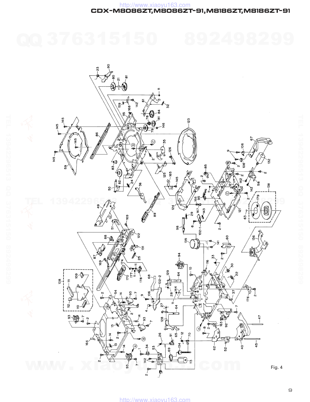
CDX-M8086ZT,M8086ZT-91,M8186ZT,M8186ZT-91
Fig. 4
www. xiaoyu163. com
QQ 376315150
9
9
2
8
9
4
2
9
8
TEL 13942296513
9
9
2
8
9
4
2
9
8
0
5
1
5
1
3
6
7
3
Q
Q
TEL 13942296513 QQ 376315150 892498299
TEL 13942296513 QQ 376315150 892498299
http://www.xiaoyu163.com
10
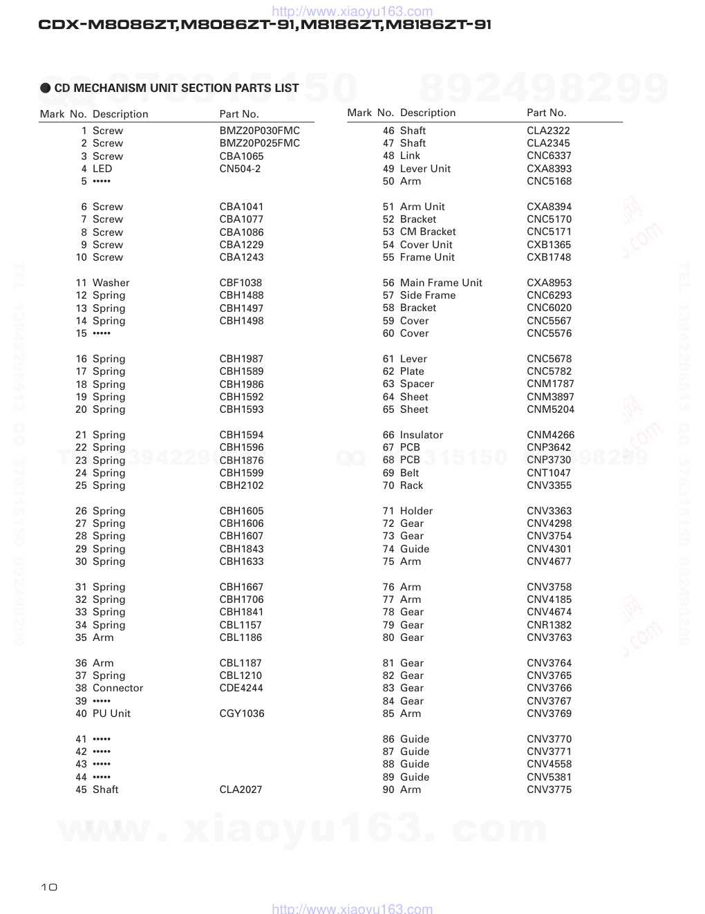
CDX-M8086ZT,M8086ZT-91,M8186ZT,M8186ZT-91
1 Screw
BMZ20P030FMC
2 Screw
BMZ20P025FMC
3 Screw
CBA1065
4 LED
CN504-2
5 •••••
6 Screw
CBA1041
7 Screw
CBA1077
8 Screw
CBA1086
9 Screw
CBA1229
10 Screw
CBA1243
11 Washer
CBF1038
12 Spring
CBH1488
13 Spring
CBH1497
14 Spring
CBH1498
15 •••••
16 Spring
CBH1987
17 Spring
CBH1589
18 Spring
CBH1986
19 Spring
CBH1592
20 Spring
CBH1593
21 Spring
CBH1594
22 Spring
CBH1596
23 Spring
CBH1876
24 Spring
CBH1599
25 Spring
CBH2102
26 Spring
CBH1605
27 Spring
CBH1606
28 Spring
CBH1607
29 Spring
CBH1843
30 Spring
CBH1633
31 Spring
CBH1667
32 Spring
CBH1706
33 Spring
CBH1841
34 Spring
CBL1157
35 Arm
CBL1186
36 Arm
CBL1187
37 Spring
CBL1210
38 Connector
CDE4244
39 •••••
40 PU Unit
CGY1036
41 •••••
42 •••••
43 •••••
44 •••••
45 Shaft
CLA2027
46 Shaft
CLA2322
47 Shaft
CLA2345
48 Link
CNC6337
49 Lever Unit
CXA8393
50 Arm
CNC5168
51 Arm Unit
CXA8394
52 Bracket
CNC5170
53 CM Bracket
CNC5171
54 Cover Unit
CXB1365
55 Frame Unit
CXB1748
56 Main Frame Unit
CXA8953
57 Side Frame
CNC6293
58 Bracket
CNC6020
59 Cover
CNC5567
60 Cover
CNC5576
61 Lever
CNC5678
62 Plate
CNC5782
63 Spacer
CNM1787
64 Sheet
CNM3897
65 Sheet
CNM5204
66 Insulator
CNM4266
67 PCB
CNP3642
68 PCB
CNP3730
69 Belt
CNT1047
70 Rack
CNV3355
71 Holder
CNV3363
72 Gear
CNV4298
73 Gear
CNV3754
74 Guide
CNV4301
75 Arm
CNV4677
76 Arm
CNV3758
77 Arm
CNV4185
78 Gear
CNV4674
79 Gear
CNR1382
80 Gear
CNV3763
81 Gear
CNV3764
82 Gear
CNV3765
83 Gear
CNV3766
84 Gear
CNV3767
85 Arm
CNV3769
86 Guide
CNV3770
87 Guide
CNV3771
88 Guide
CNV4558
89 Guide
CNV5381
90 Arm
CNV3775
- CD MECHANISM UNIT SECTION PARTS LIST
Mark No. Description
Part No.
Mark No. Description
Part No.
www. xiaoyu163. com
QQ 376315150
9
9
2
8
9
4
2
9
8
TEL 13942296513
9
9
2
8
9
4
2
9
8
0
5
1
5
1
3
6
7
3
Q
Q
TEL 13942296513 QQ 376315150 892498299
TEL 13942296513 QQ 376315150 892498299
http://www.xiaoyu163.com
CDX-M8086ZT,M8086ZT-91,M8186ZT,M8186ZT-91
91 Bearing
CNV3778
92 Holder
CNV3779
93 Damper
CNV3780
94 Cam
CNV4593
95 Guide
CNV3784
96 Guide
CNV3785
97 Arm
CNV3787
98 Plate
CNV3912
99 Arm
CNV4977
100 Gathering PCB
CNX2467
101 •••••
102 Gathering PCB
CNX2466
103 •••••
104 •••••
105 •••••
106 Switch
CSN1012
107 Switch
CSN1025
108 PCB Unit
CWX1809
109 Connector
CKS1944
110 Connector
CKS1955
111 Connector
CKS1968
112 Connector
CKS2406
113 Motor Unit
CXA4649
114 Damper Unit
CXB1815
115 Stage Chassis Unit
CXA6608
116 CRG Chassis Unit
CXB1757
117 Steer Unit
CXA6610
118 Bracket Unit
CXA8395
119 Holder Unit
CXB1364
120 Lever Unit
CXA8399
121 Lower Cover Unit
CXA9196
122 Bracket Unit
CXB2731
123 Cam Ring Unit
CXA6616
124 Lever Unit
CXA8390
125 Lever Unit
CXA6620
126 Link Unit
CXA6621
127 Arm Unit
CXA6622
128 Arm Unit
CXB1120
129 Arm Unit
CXA6624
130 Frame Unit
CXB1710
131 Lever Unit
CXA8421
132 Motor Unit
CXA8656
133 Motor Unit
CXB1407
134 Screw Unit
CXA6990
135 Motor Unit
CXA8217
136 Arm Unit
CXA8957
137 •••••
138 Clamper Unit
CXA7632
139 •••••
140 •••••
141 Screw
JFZ17P025FNI
142 Screw
JFZ20P025FNI
143 Photo-transistor
PT4800
144 Spring
CBH1741
145 Screw
JFZ20P014FMC
146 Washer
CBF1002
147 Screw
CBA1340
148 Spring
CBL1254
149 Spring
CBL1229
150 Arm
CNC6488
151 Spring
CBL1230
152 Holder
CNV4440
153 Guide
CNV4524
154 Spring
CBL1203
155 Washer
YE25FUC
156 •••••
157 Bracket
CNC6016
158 Screw
JFZ20P020FZK
159 Cushion
CNM4495
160 Arm
CNV4292
161 Gear
CNV4299
162 Bracket Unit
CXA8396
163 Spring
CBL1226
164 Sheet
CNM4552
165 Spring
CBL1253
166 Spring
CBH1778
167 Holder
CNV4290
168 Bracket
CNC6097
169 Screw
CBA1037
170 Guide
CNV4296
171 Connector
CDE4968
172 Shaft
CLA3328
173 Screw
BMZ26P030FZK
174 Washer
CBF1037
175 •••••
176 Spring
CBL1250
177 Spring
CBH1783
178 Lever Unit
CXA8392
179 Sheet
CNM4071
180 •••••
181 Gear
CNV4675
182 Spring
CBH1989
183 Spring
CBH1988
184 Spring
CBH1847
185 Spring
CBL1216
186 Cushion
CNM5403
Mark No. Description
Part No.
Mark No. Description
Part No.
11
www. xiaoyu163. com
QQ 376315150
9
9
2
8
9
4
2
9
8
TEL 13942296513
9
9
2
8
9
4
2
9
8
0
5
1
5
1
3
6
7
3
Q
Q
TEL 13942296513 QQ 376315150 892498299
TEL 13942296513 QQ 376315150 892498299
http://www.xiaoyu163.com
12
CDX-M8086ZT,M8086ZT-91,M8186ZT,M8186ZT-91
1
2
3
4
1
3
4
D
C
B
A
3. SCHEMATIC DIAGRAM
3.1 OVERALL CONNECTION DIAGRAM(GUIDE PAGE)
Note: When ordering service parts,be sure to refer to "EXPLODED VIEWS AND PARTS LIST"or"ELECTRICAL PARTS
LIST".
PD5408A
BA6797FM
DTA123JK
CXA8217
CXA8656
A-a
A-b
A-a
A-b
A-b
A-a
Large size
SCH diagram
Guide page
Detailed page
A B C D
D-a
www. xiaoyu163. com
QQ 376315150
9
9
2
8
9
4
2
9
8
TEL 13942296513
9
9
2
8
9
4
2
9
8
0
5
1
5
1
3
6
7
3
Q
Q
TEL 13942296513 QQ 376315150 892498299
TEL 13942296513 QQ 376315150 892498299
http://www.xiaoyu163.com
13
CDX-M8086ZT,M8086ZT-91,M8186ZT,M8186ZT-91
5
6
7
8
5
6
7
8
D
C
B
A
PD5408A
R1739
100K
R1740
MMSEN
0R0
C1712
R001
R1738
CN906
SW905
CSN1039
D.CLOSE
SW904
CSN1040
EJECT
GRILLE UNIT
0R0
D-b
F
D
Fig. 5
www. xiaoyu163. com
QQ 376315150
9
9
2
8
9
4
2
9
8
TEL 13942296513
9
9
2
8
9
4
2
9
8
0
5
1
5
1
3
6
7
3
Q
Q
TEL 13942296513 QQ 376315150 892498299
TEL 13942296513 QQ 376315150 892498299
http://www.xiaoyu163.com
14
CDX-M8086ZT,M8086ZT-91,M8186ZT,M8186ZT-91
1
2
3
4
1
2
3
4
D
C
B
A
BA6797FM
D-a
D-a D-b
A
www. xiaoyu163. com
QQ 376315150
9
9
2
8
9
4
2
9
8
TEL 13942296513
9
9
2
8
9
4
2
9
8
0
5
1
5
1
3
6
7
3
Q
Q
TEL 13942296513 QQ 376315150 892498299
TEL 13942296513 QQ 376315150 892498299
http://www.xiaoyu163.com
15
CDX-M8086ZT,M8086ZT-91,M8186ZT,M8186ZT-91
5
6
7
8
5
6
7
8
D
C
B
A
PD5408A
DTA123JK
CXA8217
CXA8656
D-a
D-a D-b
B C
Fig. 6
www. xiaoyu163. com
QQ 376315150
9
9
2
8
9
4
2
9
8
TEL 13942296513
9
9
2
8
9
4
2
9
8
0
5
1
5
1
3
6
7
3
Q
Q
TEL 13942296513 QQ 376315150 892498299
TEL 13942296513 QQ 376315150 892498299
http://www.xiaoyu163.com
16
CDX-M8086ZT,M8086ZT-91,M8186ZT,M8186ZT-91
1
2
3
4
1
2
3
4
D
C
B
A
D-a D-b
D-b
www. xiaoyu163. com
QQ 376315150
9
9
2
8
9
4
2
9
8
TEL 13942296513
9
9
2
8
9
4
2
9
8
0
5
1
5
1
3
6
7
3
Q
Q
TEL 13942296513 QQ 376315150 892498299
TEL 13942296513 QQ 376315150 892498299
http://www.xiaoyu163.com
17
CDX-M8086ZT,M8086ZT-91,M8186ZT,M8186ZT-91
5
6
7
8
5
6
7
8
D
C
B
A
D-b
D-a D-b
PD5408A
R1739
SW905
CN906
R1738
0R0
CSN1039
D.CLOSE
SW904
CSN1040
EJECT
GRILLE UNIT
100K
R1740
C1712
R001
MMSEN
0R0
F
Fig. 7
www. xiaoyu163. com
QQ 376315150
9
9
2
8
9
4
2
9
8
TEL 13942296513
9
9
2
8
9
4
2
9
8
0
5
1
5
1
3
6
7
3
Q
Q
TEL 13942296513 QQ 376315150 892498299
TEL 13942296513 QQ 376315150 892498299
http://www.xiaoyu163.com
18
CDX-M8086ZT,M8086ZT-91,M8186ZT,M8186ZT-91
1 RFO
0.5V/div. 0.5µs/div.
Normal mode: play
4 CH1: TEY
0.5V/div.
5 CH2: TIN
1V/div.
Test mode: Single jump (FWD)
0.5ms/div.
4 CH1: TEY
0.5V/div.
5 CH2: TIN
0.5V/div.
Normal mode: Play
20ms/div.
2 CH1: FIN
1V/div.
3 CH2: FO+
2V/div.
Test mode: No disc, Focus close
0.2s/div.
2 CH1: FIN
1V/div.
7 CH2: SIN
1V/div.
Normal mode: Focus close (12cm)
0.5s/div.
REFO →
4 CH1: TEY
0.5V/div.
5 CH2: TIN
1V/div.
Test mode: 32 track jump (FWD)
0.5ms/div.
4 CH1: TEY
0.5V/div.
5 CH2: TIN
1V/div.
Test mode: 100 track jump (FWD)
5ms/div.
4 CH1: TEY
0.5V/div.
6 CH2: FEY
0.5V/div.
Normal mode: AGC after focus
close
0.1s/div.
6 CH1: FEY
0.2V/div.
2 CH2: FIN
0.5V/div.
Normal mode: Play
20ms/div.
2 CH1: FIN
1V/div.
7 CH2: SIN
1V/div.
Normal mode: Focus close (8cm)
0.5s/div.
@ DATA
2V/div.
10µs/div.
Play
REFO →
REFO →
REFO →
REFO →
REFO →
REFO →
REFO →
REFO →
REFO →
REFO →
REFO →
REFO →
REFO →
REFO →
REFO →
REFO →
REFO →
REFO →
REFO →
REFO →
7 SIN
0.5V/div.
10ms/div.
Search (12cm disc)
REFO →
- Waveforms
Note:1. The encircled numbers denote measuring pointes in the circuit diagram.
2. Reference voltage
REFO:2.5V
www. xiaoyu163. com
QQ 376315150
9
9
2
8
9
4
2
9
8
TEL 13942296513
9
9
2
8
9
4
2
9
8
0
5
1
5
1
3
6
7
3
Q
Q
TEL 13942296513 QQ 376315150 892498299
TEL 13942296513 QQ 376315150 892498299
http://www.xiaoyu163.com
19
CDX-M8086ZT,M8086ZT-91,M8186ZT,M8186ZT-91
4 CH1: TEY
0.5V/div.
8 CH2: CIN
0.5V/div.
Test mode: 100 track jump (FWD)
4 CH1: TEY
0.5V/div.
5 CH2: TIN
0.5V/div.
Normal mode: During AGC
1ms/div.
# LRCK
2V/div.
20µs/div.
Play
! SCKO
2V/div.
1µs/div.
Play
5ms/div.
REFO →
REFO →
REFO →
REFO →
REFO →
REFO →
GND →
7 SIN
0.5V/div.
0.1s/div.
Normal mode: 1Play (12cm disc)
REFO →
6 CH1: FEY
0.2V/div.
2 CH2: FIN
1V/div.
Normal mode: During AGC
1ms/div.
REFO →
REFO →
9 EFM
1V/div.
5µs/div.
Play
GND →
REFO →
4 CH1: TEY
1V/div.
0 CH2: TEC
1V/div.
Test mode: Focus close
Tracking open
2ms/div.
REFO →
REFO →
www. xiaoyu163. com
QQ 376315150
9
9
2
8
9
4
2
9
8
TEL 13942296513
9
9
2
8
9
4
2
9
8
0
5
1
5
1
3
6
7
3
Q
Q
TEL 13942296513 QQ 376315150 892498299
TEL 13942296513 QQ 376315150 892498299
http://www.xiaoyu163.com
20
CDX-M8086ZT,M8086ZT-91,M8186ZT,M8186ZT-91
1
2
3
4
1
2
3
4
D
C
B
A
4R7/35
4R7/35
4R7/35
4R7/35
EXTENSION UNIT
75
E
3.2 EXTENSION UNIT
www. xiaoyu163. com
QQ 376315150
9
9
2
8
9
4
2
9
8
TEL 13942296513
9
9
2
8
9
4
2
9
8
0
5
1
5
1
3
6
7
3
Q
Q
TEL 13942296513 QQ 376315150 892498299
TEL 13942296513 QQ 376315150 892498299
http://www.xiaoyu163.com
21
CDX-M8086ZT,M8086ZT-91,M8186ZT,M8186ZT-91
5
6
7
8
5
6
7
8
D
C
B
A
RD18JS
RD18JS
RD18JS
RD18JS
RD18JS
RD18JS
RD18JS
RD18JS
GP30ML-6373
75
E
Fig. 8
www. xiaoyu163. com
QQ 376315150
9
9
2
8
9
4
2
9
8
TEL 13942296513
9
9
2
8
9
4
2
9
8
0
5
1
5
1
3
6
7
3
Q
Q
TEL 13942296513 QQ 376315150 892498299
TEL 13942296513 QQ 376315150 892498299
http://www.xiaoyu163.com
22
CDX-M8086ZT,M8086ZT-91,M8186ZT,M8186ZT-91
1
2
3
4
1
2
3
4
D
C
B
A
4. PCB CONNECTION DIAGRAM
4.1 MAIN UNIT
Capacitor
Connector
P.C.Board
Chip Part
SIDE A
SIDE B
NOTE FOR PCB DIAGRAMS
1. The parts mounted on this PCB
include all necessary parts for
several destination.
For further information for
respective destinations, be
sure to check with the
schematic diagram.
2. Viewpoint of PCB diagrams
C
F
D
MAIN UNIT
D
www. xiaoyu163. com
QQ 376315150
9
9
2
8
9
4
2
9
8
TEL 13942296513
9
9
2
8
9
4
2
9
8
0
5
1
5
1
3
6
7
3
Q
Q
TEL 13942296513 QQ 376315150 892498299
TEL 13942296513 QQ 376315150 892498299
http://www.xiaoyu163.com
23
CDX-M8086ZT,M8086ZT-91,M8186ZT,M8186ZT-91
5
6
7
8
5
6
7
8
D
C
B
A
SIDE A
A
E
Fig. 9
D
www. xiaoyu163. com
QQ 376315150
9
9
2
8
9
4
2
9
8
TEL 13942296513
9
9
2
8
9
4
2
9
8
0
5
1
5
1
3
6
7
3
Q
Q
TEL 13942296513 QQ 376315150 892498299
TEL 13942296513 QQ 376315150 892498299
http://www.xiaoyu163.com
24
CDX-M8086ZT,M8086ZT-91,M8186ZT,M8186ZT-91
1
2
3
4
1
2
3
4
D
C
B
A
D
MAIN UNIT
D
www. xiaoyu163. com
QQ 376315150
9
9
2
8
9
4
2
9
8
TEL 13942296513
9
9
2
8
9
4
2
9
8
0
5
1
5
1
3
6
7
3
Q
Q
TEL 13942296513 QQ 376315150 892498299
TEL 13942296513 QQ 376315150 892498299
http://www.xiaoyu163.com
25
CDX-M8086ZT,M8086ZT-91,M8186ZT,M8186ZT-91
5
6
7
8
5
6
7
8
D
C
B
A
SIDE B
Fig. 10
D
www. xiaoyu163. com
QQ 376315150
9
9
2
8
9
4
2
9
8
TEL 13942296513
9
9
2
8
9
4
2
9
8
0
5
1
5
1
3
6
7
3
Q
Q
TEL 13942296513 QQ 376315150 892498299
TEL 13942296513 QQ 376315150 892498299
http://www.xiaoyu163.com
26
CDX-M8086ZT,M8086ZT-91,M8186ZT,M8186ZT-91
1
2
3
4
1
2
3
4
D
C
B
A
D
E
4.2 EXTENSION UNIT
EXTENSION UNIT
Fig. 11
SIDE A
E
www. xiaoyu163. com
QQ 376315150
9
9
2
8
9
4
2
9
8
TEL 13942296513
9
9
2
8
9
4
2
9
8
0
5
1
5
1
3
6
7
3
Q
Q
TEL 13942296513 QQ 376315150 892498299
TEL 13942296513 QQ 376315150 892498299
http://www.xiaoyu163.com
27
CDX-M8086ZT,M8086ZT-91,M8186ZT,M8186ZT-91
1
2
3
4
1
2
3
4
D
C
B
A
E
EXTENSION UNIT
Fig. 12
SIDE B
E
www. xiaoyu163. com
QQ 376315150
9
9
2
8
9
4
2
9
8
TEL 13942296513
9
9
2
8
9
4
2
9
8
0
5
1
5
1
3
6
7
3
Q
Q
TEL 13942296513 QQ 376315150 892498299
TEL 13942296513 QQ 376315150 892498299
http://www.xiaoyu163.com
28
CDX-M8086ZT,M8086ZT-91,M8186ZT,M8186ZT-91
1
2
3
4
1
2
3
4
D
C
B
A
C
PHOTO PCB
4.3 GRILLE UNIT,PHOTO PCB
Fig. 15
C F
GRILLE UNIT
F
Fig. 13
GRILLE UNIT
F
Fig. 14
CN1702
SIDE A
SIDE B
D
www. xiaoyu163. com
QQ 376315150
9
9
2
8
9
4
2
9
8
TEL 13942296513
9
9
2
8
9
4
2
9
8
0
5
1
5
1
3
6
7
3
Q
Q
TEL 13942296513 QQ 376315150 892498299
TEL 13942296513 QQ 376315150 892498299
http://www.xiaoyu163.com
29
CDX-M8086ZT,M8086ZT-91,M8186ZT,M8186ZT-91
1
2
3
4
1
2
3
4
D
C
B
A
A
PCB UNIT
B
MECHANISM PCB
Fig. 16
Fig. 17
4.4 PCB UNIT,MECHANISM PCB
A B
PU UNIT
CN1801
www. xiaoyu163. com
QQ 376315150
9
9
2
8
9
4
2
9
8
TEL 13942296513
9
9
2
8
9
4
2
9
8
0
5
1
5
1
3
6
7
3
Q
Q
TEL 13942296513 QQ 376315150 892498299
TEL 13942296513 QQ 376315150 892498299
http://www.xiaoyu163.com
30
CDX-M8086ZT,M8086ZT-91,M8186ZT,M8186ZT-91
Unit Number : CWX2126
Unit Name
: Extension Unit
MISCELLANEOUS
IC
851
IC
NJM2068MD
IC
852
IC
NJM2068MD
IC
853
IC
TC74HC4066AF
IC
951
IC
NJM78L05A
IC
952
IC
TC7W04F
Q
851
Transistor
DTC343TS
Q
852
Transistor
DTC343TS
Q
853
Transistor
DTA144EK
Q
854
Transistor
DTA144ES
Q
855
Transistor
DTC144ES
Q
856
Transistor
DTA144EK
Q
901
Transistor
2SC2458
Q
911
Transistor
2SB942A
Q
912
Transistor
2SD1859
Q
913
Transistor
2SD1859
D
854
Diode
RD18JS
D
856
Diode
RD18JS
D
858
Diode
RD18JS
D
860
Diode
RD18JS
D
861
Diode
1SS133
D
901
Diode
GP30ML-6373
D
902
Diode
ERA15-02VH
D
903
Diode
RD18JS
D
904
Diode
RD18JS
D
905
Diode
HZS6L(C1)
D
931
Diode
RD18JS
D
932
Diode
RD18JS
L
901
Choke Coil 1.4mH
CTH1129
L
951
Transformer
CTC1075
EF
901
EMI Filter
CCG1006
RESISTORS
R
849
RS1/10S222J
R
850
RS1/10S222J
R
851
RS1/10S222J
R
852
RS1/10S222J
R
853
RS1/10S752J
R
854
RS1/10S752J
R
855
RS1/10S103J
R
856
RS1/10S103J
R
857
RS1/10S103J
R
858
RS1/10S103J
R
859
RS1/10S103J
R
860
RS1/10S103J
R
861
RS1/10S103J
R
862
RS1/10S103J
R
863
RS1/10S750J
R
864
RS1/10S750J
R
865
RS1/10S750J
R
866
RS1/10S750J
R
867
RS1/8S510J
R
868
RS1/8S510J
R
869
RS1/8S510J
R
870
RS1/8S510J
R
871
RS1/10S102J
R
873
RS1/10S103J
R
874
RS1/10S223J
R
875
RS1/10S223J
R
901
RS1/10S184J
R
902
RN1/10SE7502D
R
903
RD1/4PU183J
R
904
RN1/10SE7501D
R
905
RS1/10S102J
R
907
RD1/4PU472J
R
911
RS1/10S103J
R
912
RS1/8S201J
R
913
RS1/8S201J
R
914
RS1/10S101J
R
915
RS1/8S241J
R
916
RN1/10SE5100D
R
917
RN1/10SE6800D
R
918
RS1/10S202J
R
919
RS1/10S182J
R
920
RS1/10S622J
R
921
RD1/4PU221J
R
922
RS1/10S223J
R
923
RS1/10S103J
R
925
RS1/10S0R0J
R
931
RD1/4PU101J
R
932
RD1/4PU101J
R
951
RS1/10S101J
R
952
RD1/4PU750J
CAPACITORS
C
847
CCSQCH821J50
C
848
CCSQCH821J50
C
849
CCSQCH821J50
C
850
CCSQCH821J50
C
851
CEJA4R7M35
C
852
CEJA4R7M35
C
853
CEJA4R7M35
C
854
CEJA4R7M35
C
855
CCSQCH821J50
C
856
CCSQCH821J50
C
857
CCSQCH181J50
C
858
CCSQCH181J50
C
859
CKSQYB473K50
C
860
CKSQYB473K50
C
861
CCSQCH560J50
C
862
CCSQCH560J50
C
863
CKSQYB153K50
C
864
CKSQYB153K50
C
865
CKSQYB153K50
C
866
CKSQYB153K50
C
867
CEJANP4R7M16
C
868
CEJANP4R7M16
C
869
CEJANP4R7M16
C
870
CEJANP4R7M16
C
871
CKSQYB224K16
5. ELECTRICAL PARTS LIST
NOTE:
- Parts whose parts numbers are omitted are subject to being not supplied.
- The part numbers shown below indicate chip components.
Chip Resistor
RS1/_S___J,RS1/__S___J
Chip Capacitor (except for CQS.....)
CKS....., CCS....., CSZS.....
=====Circuit Symbol and No.===Part Name
Part No.
---------------------------------------------------
-------------------------
=====Circuit Symbol and No.===Part Name
Part No.
---
------
------------------------------------------
-------------------------
E
www. xiaoyu163. com
QQ 376315150
9
9
2
8
9
4
2
9
8
TEL 13942296513
9
9
2
8
9
4
2
9
8
0
5
1
5
1
3
6
7
3
Q
Q
TEL 13942296513 QQ 376315150 892498299
TEL 13942296513 QQ 376315150 892498299
http://www.xiaoyu163.com
31
CDX-M8086ZT,M8086ZT-91,M8186ZT,M8186ZT-91
C
901
330µF/25V
CCH1281
C
902
330µF/25V
CCH1281
C
903
330µF/25V
CCH1281
C
905
CKSYB224K25
C
907
CKSQYB102K50
C
911
CEHAR220M16
C
912
CKSQYB473K50
C
913
CEJA101M6R3
C
931
CCSQCH221J50
C
932
CCSQCH221J50
C
941
CKSQYB473K50
C
942
CCSQCH220J50
C
943
CCSQCH221J50
C
951
CKSQYB473K50
C
952
CKSQYB473K50
C
953
CEJA2R2M50
C
954
CKSQYB103K50
C
955
CEJA470M16
C
956
CCSQCH680J50
C
957
CCSQCH470J50
C
958
CKSQYB473K50
Unit Number : CWX2123
Unit Name
: Main Unit
MISCELLANEOUS
IC
1001
IC
UPC2571GS
IC
1201
IC
UPD63700AGF
IC
1401
IC
BA6797FM
IC
1601
IC
SM5874AMP
IC
1602
IC
NJM2068MD
IC
1701
IC
PD5408A
IC
1703
IC
HA12187FP
IC
1704
IC
PAJ002A
IC
1801
IC
LB1836M
Q
1001
Transistor
2SA1015
Q
1401
Transistor
2SB1238
Q
1707
Transistor
DTA123JS
Q
1708
Transistor
DTC114YS
Q
1709
Transistor
2SB1238
Q
1801
Transistor
DTA123JK
Q
1802
Transistor
UN2211
Q
1803
Transistor
2SB1184F5
Q
1804
Transistor
UN2219
D
1401
Diode
ERA15-02VH
D
1402
Diode
ERA15-02VH
D
1403
Diode
ERA15-02VH
D
1801
Diode
ERA15-02VH
D
1802
Diode
ERA15-02VH
D
1803
Diode
RB100AVH
TH 1701
Thermistor
CCX1015
X
1601
Crystal Resonator 16.9344MHz
CSS1052
X
1701
Ceramic Resonator 6.29MHz
CSS1310
VR 1001
Semi-fixed 2.2kΩ(B)
CCP1177
VR 1002
Semi-fixed 22kΩ(B)
CCP1183
VR 1003
Semi-fixed 47kΩ(B)
CCP1185
VR 1004
Semi-fixed 47kΩ(B)
CCP1185
TP 1001
Checker Chip(TEY)
CKF1031
TP 1002
Checker Chip(FEY)
CKF1031
TP 1003
Checker Chip(RFO)
CKF1031
TP 1004
Checker Chip(5VA)
CKF1031
TP 1005
Checker Chip(REFO)
CKF1031
TP 1006
Checker Chip(E)
CKF1031
TP 1007
Checker Chip(F)
CKF1031
RESISTORS
R
1001
RS1/8S100J
R
1002
RS1/8S120J
R
1003
RS1/16S103J
R
1004
RS1/16S102J
R
1005
RS1/16S823J
R
1006
RS1/16S182J
R
1007
RS1/16S333J
R
1011
RS1/16S683J
R
1012
RS1/16S683J
R
1013
RS1/16S102J
R
1014
RS1/16S473J
R
1018
RS1/16S622J
R
1019
RS1/16S563J
R
1020
RS1/16S622J
R
1021
RS1/16S513J
R
1022
RS1/16S133J
R
1024
RS1/16S102J
R
1025
RS1/16S102J
R
1027
RS1/16S183J
R
1028
RS1/16S822J
R
1030
RS1/16S102J
R
1201
RS1/16S104J
R
1202
RS1/16S473J
R
1401
RS1/16S563J
R
1402
RS1/16S163J
R
1403
RS1/16S163J
R
1404
RS1/16S753J
R
1405
RS1/16S433J
R
1406
RS1/16S103J
R
1407
RS1/16S563J
R
1408
RS1/16S133J
R
1409
RS1/16S153J
R
1410
RS1/16S473J
R
1411
RS1/16S103J
R
1412
RS1/16S152J
R
1414
RS1/16S0R0J
R
1602
RS1/16S0R0J
R
1605
RS1/16S103J
R
1606
RS1/16S103J
R
1607
RS1/16S103J
R
1608
RS1/16S103J
R
1609
RS1/16S752J
R
1610
RS1/16S752J
R
1611
RS1/16S752J
R
1612
RS1/16S752J
R
1613
RS1/16S163J
R
1614
RS1/16S163J
R
1615
RS1/16S163J
R
1616
RS1/16S163J
R
1617
RS1/16S750J
R
1618
RS1/16S750J
R
1619
RS1/16S103J
R
1620
RS1/8S3R9J
R
1701
RS1/16S513J
R
1702
RS1/16S103J
R
1703
RS1/16S154J
R
1704
RS1/16S753J
R
1705
RS1/16S104J
R
1706
RS1/16S104J
R
1708
RS1/16S433J
R
1709
RS1/16S222J
R
1710
RS1/16S222J
R
1712
RS1/16S103J
R
1713
RS1/16S104J
R
1714
RS1/16S222J
=====Circuit Symbol and No.===Part Name
Part No.
---
------
------------------------------------------
-------------------------
=====Circuit Symbol and No.===Part Name
Part No.
---
------
------------------------------------------
-------------------------
D
www. xiaoyu163. com
QQ 376315150
9
9
2
8
9
4
2
9
8
TEL 13942296513
9
9
2
8
9
4
2
9
8
0
5
1
5
1
3
6
7
3
Q
Q
TEL 13942296513 QQ 376315150 892498299
TEL 13942296513 QQ 376315150 892498299
http://www.xiaoyu163.com
32
CDX-M8086ZT,M8086ZT-91,M8186ZT,M8186ZT-91
R
1716
RS1/16S563J
R
1717
RS1/16S153J
R
1718
RS1/16S104J
R
1719
RS1/16S0R0J
R
1721
RS1/16S104J
R
1722
RS1/16S222J
R
1729
RS1/16S222J
R
1730
RS1/16S104J
R
1731
RS1/16S104J
R
1732
RS1/16S104J
R
1733
RS1/16S104J
R
1734
RS1/16S104J
R
1735
RS1/16S222J
R
1736
RS1/16S222J
R
1737
RS1/16S104J
R
1738
RS1/16S0R0J
R
1739
RS1/16S104J
R
1740
RS1/16S0R0J
R
1741
RS1/16S103J
R
1744
RS1/16S222J
R
1745
RS1/16S222J
R
1746
RS1/16S102J
R
1747
RS1/16S104J
R
1748
RS1/16S104J
R
1749
RS1/16S102J
R
1751
RS1/16S473J
R
1752
RS1/16S473J
R
1756
RS1/16S104J
R
1757
RS1/16S221J
R
1758
RS1/16S221J
R
1759
RS1/16S221J
R
1760
RS1/16S221J
R
1767
RS1/8S3R9J
R
1768
RS1/16S102J
R
1771
RS1/16S102J
R
1801
RS1/10S431J
R
1802
RS1/10S431J
R
1803
RS1/10S431J
R
1804
RS1/10S431J
R
1805
RS1/16S102J
R
1806
RS1/8S910J
R
1807
RS1/8S910J
R
1808
RS1/8S910J
CAPACITORS
C
1001
CKSRYB102K50
C
1002
CEAS101M10
C
1003
CKSQYB104K16
C
1004
CEAS470M10
C
1005
CCSRCH101J50
C
1006
CKSRYB561K50
C
1007
CKSYB334K16
C
1008
CKSRYB102K50
C
1009
CCSRCH181J50
C
1010
CKSRYB102K50
C
1011
CKSRYB102K50
C
1013
CKSRYB103K25
C
1014
CCSRCH220J50
C
1015
CKSYB334K16
C
1018
CEJA220M6R3
C
1021
CKSQYB104K16
C
1022
CKSRYB332K50
C
1023
CKSRYB561K50
C
1201
CKSYB334K16
C
1202
CKSYB104K16
C
1203
CKSRYB471K50
C
1204
CKSRYB102K50
C
1401
CSZA220M16
C
1402
CKSQYB103K50
C
1403
CKSQYB153K50
C
1404
CEAS221M10
C
1405
CEAS221M10
C
1406
CKSRYB152K50
C
1407
CKSRYB821K50
C
1408
CKSRYB271K50
C
1409
22µF/16V
CCL1044
C
1602
CKSQYB104K16
C
1603
CKSQYB104K16
C
1604
CKSQYB104K16
C
1605
CKSQYB104K16
C
1606
CCSRCH8R0D50
C
1607
CCSRCH8R0D50
C
1608
CEAS221M10
C
1609
CCSRCH221J50
C
1610
CCSRCH221J50
C
1611
CCSRCH680J50
C
1612
CCSRCH680J50
C
1613
CCSRCH680J50
C
1614
CCSRCH680J50
C
1616
CKSYB224K16
C
1701
CKSRYB103K25
C
1703
CSZST330M16
C
1705
CKSRYB103K25
C
1706
CKSRYB103K50
C
1707
CKSRYB103K25
C
1710
CKSRYB103K25
C
1711
CKSRYB102K50
C
1712
CKSRYB102K50
C
1802
CEAL220M16
Unit Number : CWM5438
Unit Name
: Grille Unit
MISCELLANEOUS
SW
904
Switch(Eject)
CSN1040
SW
905
Switch(D.Close)
CSN1039
Unit Number :
CWX1809
Unit Name
:
PCB Unit
C
801
CKSQYB102K50
C
802
CKSQYB102K50
Unit Number :
Unit Name
:
Mechanism PCB
D
802
LED
CN504-2
S
805
Switch(Home)
CSN1012
Unit Number :
Unit Name
:
Photo PCB
D
801
LED
CN504-2
S
801
Switch(RSTP)
CSN1025
S
802
Switch(MAG)
CSN1012
Miscellaneous Parts List
PU Unit
CGY1036
M
801
Motor Unit(Spindle)
CXA8217
M
802
Motor Unit(Elevation)
CXB1407
M
803
Motor Unit(Tray)
CXA8656
M
804
Motor Unit(Carriage)
CXA4649
P
801
Photo-Transistor
PT4800
P
802
Photo-Transistor
PT4800
S
803
Switch(TRP)
CSN1012
S
804
Switch(DSP)
CSN1012
=====Circuit Symbol and No.===Part Name
Part No.
---
------
------------------------------------------
-------------------------
=====Circuit Symbol and No.===Part Name
Part No.
---
------
------------------------------------------
-------------------------
A
B
C
F
www. xiaoyu163. com
QQ 376315150
9
9
2
8
9
4
2
9
8
TEL 13942296513
9
9
2
8
9
4
2
9
8
0
5
1
5
1
3
6
7
3
Q
Q
TEL 13942296513 QQ 376315150 892498299
TEL 13942296513 QQ 376315150 892498299
http://www.xiaoyu163.com
33
CDX-M8086ZT,M8086ZT-91,M8186ZT,M8186ZT-91
6. ADJUSTMENT
1)Precautions
• This unit uses a single power supply (+5V) for the reg-
ulator. The signal reference potential, therefore, is
connected to REFO(approx. 2.5V) instead of GND.
If REFO and GND are connected to each other by mis-
take during adjustments,not only will it be impossible
to measure the potential correctly,but the servo will
malfunction and a severe shock will be applied to the
pick-up. To avoid this,take special note of the follow-
ing.
Do not connect the negative probe of the measuring
equipment to REFO and GND together. It is especially
important not to connect the channel 1 negative
probe of the oscilloscope to REFO with the channel 2
negative probe connected to GND.
Since the frame of the measuring instrument is usual-
ly at the same potential as the negative probe,change
the frame of the measuring instrument to floating sta-
tus.
If by accident REFO comes in contact with
GND,immediately switch the regulator or power OFF.
• Always make sure the regulator is OFF when connect-
ing and disconnecting the various filters and wiring
required for measurements.
• Before proceeding to further adjustments and mea-
surements after switching regulator ON,let the player
run for about one minute to allow the circuits to stabi-
lize.
• Since the protective systems in the unit’s software are
rendered inoperative in test mode,be very careful to
avoid mechanical and /or electrical shocks to the sys-
tem when making adjustment.
• With this system, elevation is detected by the photo-
transistor. Therefore, if light hits the phototransistor,
elevation may operate incorrectly. Should the system
be operated with the upper case removed, use some
opaque material to shield the photo transistor from
light.
• When unloading magazine during adjustment proce-
dures,always wait for the magazine to be properly
ejected before pressing another key.
• Turn power off when pressing the TRK UP or TRK
DOWN button during focus search in the test mode.
(Or else lens may stick and the actuator may be dam-
aged.)
2)Test Mode
• This unit is adjusted in a combination with the CD
control unit (KEX-M9076ZT/UC, etc.). During adjust-
ment, each operation should be done by using the
buttons on the CD control unit.
With the KEX-M9076ZT/UC taken up for reference, a
description will be given below concerning how to
enter into the test mode, including key operations.
The key in the adjustment text is also one of the KEX-
M9076ZT/UC keys.
• How to enter into the test mode
• Resetting the test mode
Switch ACC,back-up Off.
• SINGLE/10TRK/32TRK will continue to operate even
after the key is released.Tracking closed the moment
C-MOVE is released.
• JUMP MODE resets to SINGLE as soon as power is
switched off.
Normal mode
Diagnosis mode
CD test mode
Press the CD key three times,
while holding down the [1] and
[6] keys simultaneously.
Press the TRK UP and CD keys
simultaneously.
www. xiaoyu163. com
QQ 376315150
9
9
2
8
9
4
2
9
8
TEL 13942296513
9
9
2
8
9
4
2
9
8
0
5
1
5
1
3
6
7
3
Q
Q
TEL 13942296513 QQ 376315150 892498299
TEL 13942296513 QQ 376315150 892498299
http://www.xiaoyu163.com
34
CDX-M8086ZT,M8086ZT-91,M8186ZT,M8186ZT-91
1
CD player select
RPT
Display
版权声明
1. 本站所有素材,仅限学习交流,仅展示部分内容,如需查看完整内容,请下载原文件。
2. 会员在本站下载的所有素材,只拥有使用权,著作权归原作者所有。
3. 所有素材,未经合法授权,请勿用于商业用途,会员不得以任何形式发布、传播、复制、转售该素材,否则一律封号处理。
4. 如果素材损害你的权益请联系客服QQ:77594475 处理。