先锋PIONEER CDX-M1026ZG音响电路原理图
 "先锋PIONEER CDX-M1026ZG音响电路原理图-0")
 "先锋PIONEER CDX-M1026ZG音响电路原理图-1")
 "先锋PIONEER CDX-M1026ZG音响电路原理图-2")
 "先锋PIONEER CDX-M1026ZG音响电路原理图-3")
 "先锋PIONEER CDX-M1026ZG音响电路原理图-4")
 "先锋PIONEER CDX-M1026ZG音响电路原理图-5")
 "先锋PIONEER CDX-M1026ZG音响电路原理图-6")
 "先锋PIONEER CDX-M1026ZG音响电路原理图-7")
 "先锋PIONEER CDX-M1026ZG音响电路原理图-8")
 "先锋PIONEER CDX-M1026ZG音响电路原理图-9")
PIONEER ELECTRONIC CORPORATION
4-1, Meguro 1-Chome, Meguro-ku, Tokyo 153-8654, Japan
PIONEER ELECTRONICS SERVICE INC.
P.O.Box 1760, Long Beach, CA 90801-1760 U.S.A.
PIONEER ELECTRONIC [EUROPE] N.V.
Haven 1087 Keetberglaan 1, 9120 Melsele, Belgium
PIONEER ELECTRONICS ASIACENTRE PTE.LTD.
253 Alexandra Road, #04-01, Singapore 159936
C PIONEER ELECTRONIC CORPORATION 1999
K-ZZD. FEB. 1999 Printed in Japan
ORDER NO.
CRT2290
MULTI-COMPACT DISC PLAYER
CDX-M1026ZG
X1H/UC
Service
Manual
GM
CONTENTS
1. SAFETY INFORMATION ............................................3
2. EXPLODED VIEWS AND PARTS LIST.......................4
3. BLOCK DIAGRAM AND SCHEMATIC DIAGRAM .....9
4. PCB CONNECTION DIAGRAM ................................22
5. ELECTRICAL PARTS LIST ........................................28
6. ADJUSTMENT..........................................................31
7. GENERAL INFORMATION .......................................39
7.1 IC .........................................................................39
7.2 DIAGNOSIS ........................................................41
7.2.1 DISASSEMBLY............................................41
7.2.2 TEST MODE ................................................43
7.2.3 CONNECTOR FUNCTION DESCRIPTION..44
8. OPERATIONS AND SPECIFICATIONS.....................45
VEHICLE
DESTINATION
PRODUCED AFTER
GM PART No.
ID No.
PIONEER MODEL No.
Oldsmobile,
U.S.A., CANADA
February 1999
25659167
CDX-M1026ZG/X1H/UC
Buick, Pontiac
- See the separate manual CX-653(CRT1916) for the CD mechanism description, disassembly and circuit
description.
- The CD mechanism employed in this model is one of C6 series.
www. xiaoyu163. com
QQ 376315150
9
9
2
8
9
4
2
9
8
TEL 13942296513
9
9
2
8
9
4
2
9
8
0
5
1
5
1
3
6
7
3
Q
Q
TEL 13942296513 QQ 376315150 892498299
TEL 13942296513 QQ 376315150 892498299
http://www.xiaoyu163.com
2
CDX-M1026ZG
- CD Player Service Precautions
1. For pickup unit(Service)(CXX1235) handling, please
refer to"Disassembly"(see page 42).
During replacement, handling precautions shall be
taken to prevent an electrostatic discharge(protection
by a short pin).
2. During disassembly, be sure to turn the power off
since an internal IC might be destroyed when a con-
nector is plugged or unplugged.
3. Please checking the grating after changing the pickup
unit(see page 33) since these screws protects the
mechanism during transport, be sure to affix it when
it is transported for repair, etc.
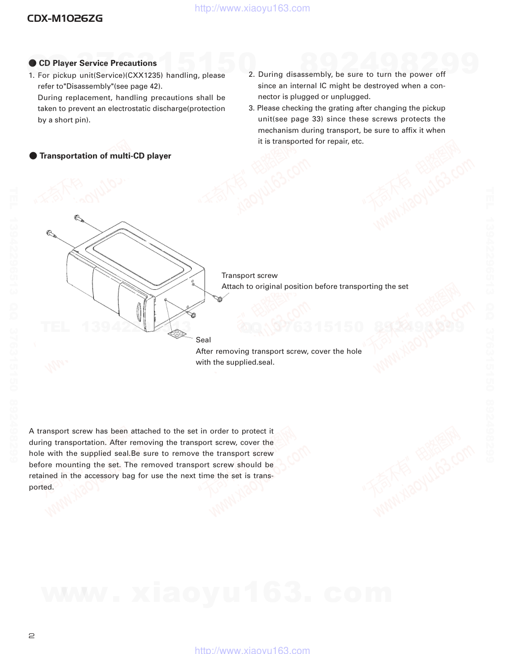
- Transportation of multi-CD player
Seal
After removing transport screw, cover the hole
with the supplied.seal.
Transport screw
Attach to original position before transporting the set
A transport screw has been attached to the set in order to protect it
during transportation. After removing the transport screw, cover the
hole with the supplied seal.Be sure to remove the transport screw
before mounting the set. The removed transport screw should be
retained in the accessory bag for use the next time the set is trans-
ported.
www. xiaoyu163. com
QQ 376315150
9
9
2
8
9
4
2
9
8
TEL 13942296513
9
9
2
8
9
4
2
9
8
0
5
1
5
1
3
6
7
3
Q
Q
TEL 13942296513 QQ 376315150 892498299
TEL 13942296513 QQ 376315150 892498299
http://www.xiaoyu163.com
3
CDX-M1026ZG
1. SAFETY INFORMATION
This service manual is intended for qualified service technicians; it is not meant for the casual do-it-yourselfer.
Qualified technicians have the necessary test equipment and tools, and have been trained to properly and safely repair
complex products such as those covered by this manual.
Improperly performed repairs can adversely affect the safety and reliability of the product and may void the warranty.
If you are not qualified to perform the repair of this product properly and safely; you should not risk trying to do so
and refer the repair to a qualified service technician.
www. xiaoyu163. com
QQ 376315150
9
9
2
8
9
4
2
9
8
TEL 13942296513
9
9
2
8
9
4
2
9
8
0
5
1
5
1
3
6
7
3
Q
Q
TEL 13942296513 QQ 376315150 892498299
TEL 13942296513 QQ 376315150 892498299
http://www.xiaoyu163.com
4
CDX-M1026ZG
2. EXPLODED VIEWS AND PARTS LIST
2.1 EXTERIOR
www. xiaoyu163. com
QQ 376315150
9
9
2
8
9
4
2
9
8
TEL 13942296513
9
9
2
8
9
4
2
9
8
0
5
1
5
1
3
6
7
3
Q
Q
TEL 13942296513 QQ 376315150 892498299
TEL 13942296513 QQ 376315150 892498299
http://www.xiaoyu163.com
5
CDX-M1026ZG
1 Screw
BMZ20P040FMC
2 Screw
BMZ26P040FMC
3 Screw
BMZ30P040FMC
4 Screw
BMZ30P040FZK
5 Screw
CBA1014
6 Screw
CBA1037
7 Screw
CBA1353
8 Spring
CBH1862
9 Spring
CBH2171
10 Connector
CDE5205
11 Transistor(Q1952)
2SB1335A
12 Upper Case
CNB2096
13 Spacer
CNC5536
14 Bracket
CNC6782
15 Holder
CNC7211
16 Holder
CNC7213
17 Seal
CNM4918
18 Insulator
CNM4973
19 PCB
CNP4402
20 Grille
CNS4146
21 Cover
CNS4153
22 Damper
CNV4502
23 Arm Unit
CXA8606
24 Lower Case Unit
CXA9466
25 Bracket Unit
CXB1636
*
26 Caution Card
HRP1090
27 Polyethylene Bag
HEG0018
28 CD Mechanism Module
CXK4551
29 Extension Unit
HWX2034
30 Screw
BMZ26P050FMC
31 Plug(CN1801)
CKS1049
32 Plug(CN1802)
CKS1050
*
33 Plug(CN1702)
CKS1052
34 Connector(CN1701)
CKS2233
35 Connector(CN1102)
CKS2398
36 Holder
CNC6672
37 Holder
CNC6784
38 Screw
BPZ20P060FMC
39 Screw
BPZ26P080FMC
40 Leaf Spring
CBL1286
41 Cord Assy
CDE5107
42 Clamper
CEF1020
43 Lighting Conductor
CNV4720
44 Grille Unit
CXA9439
45 Screw
IMS20P035FZK
46 Screw
IMS26P040FMC
47 Screw
IMS30P040FMC
48 Screw
IMS30P060FZK
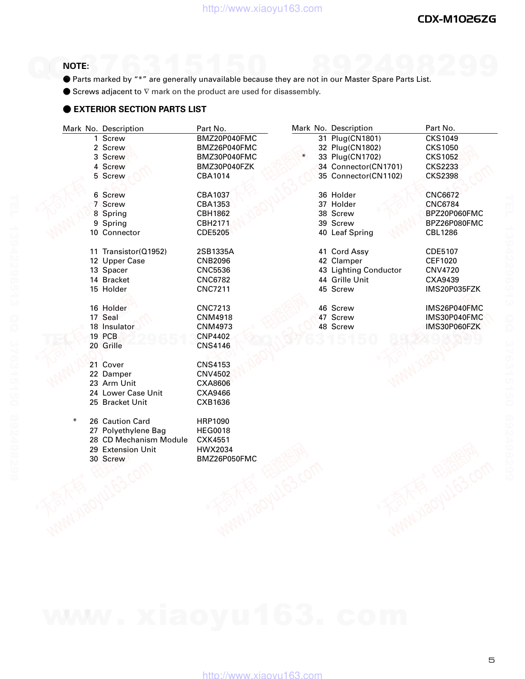
- EXTERIOR SECTION PARTS LIST
Mark No. Description
Part No.
Mark No. Description
Part No.
NOTE:
- Parts marked by “*” are generally unavailable because they are not in our Master Spare Parts List.
- Screws adjacent to ∇ mark on the product are used for disassembly.
www. xiaoyu163. com
QQ 376315150
9
9
2
8
9
4
2
9
8
TEL 13942296513
9
9
2
8
9
4
2
9
8
0
5
1
5
1
3
6
7
3
Q
Q
TEL 13942296513 QQ 376315150 892498299
TEL 13942296513 QQ 376315150 892498299
http://www.xiaoyu163.com
6
CDX-M1026ZG
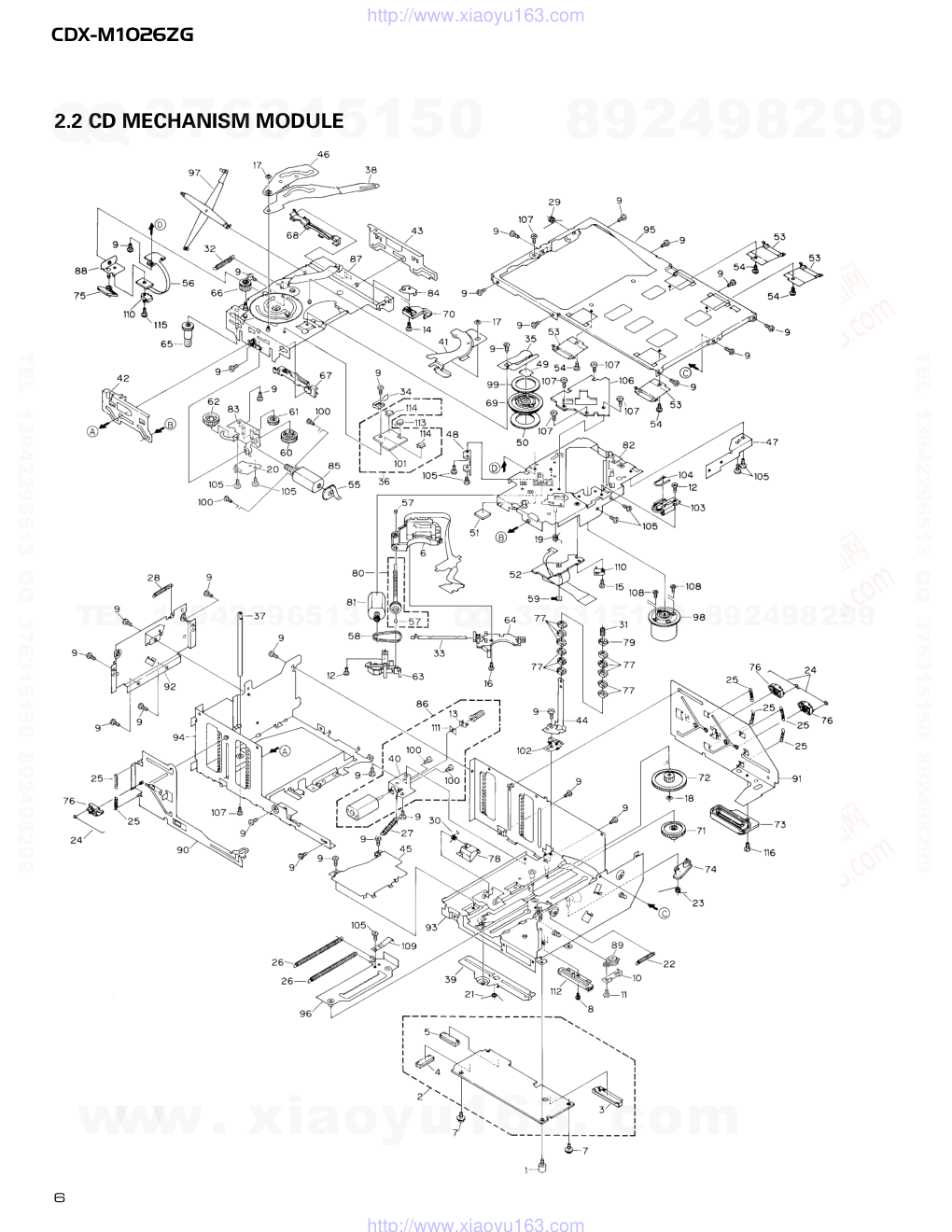
2.2 CD MECHANISM MODULE
www. xiaoyu163. com
QQ 376315150
9
9
2
8
9
4
2
9
8
TEL 13942296513
9
9
2
8
9
4
2
9
8
0
5
1
5
1
3
6
7
3
Q
Q
TEL 13942296513 QQ 376315150 892498299
TEL 13942296513 QQ 376315150 892498299
http://www.xiaoyu163.com
7
CDX-M1026ZG
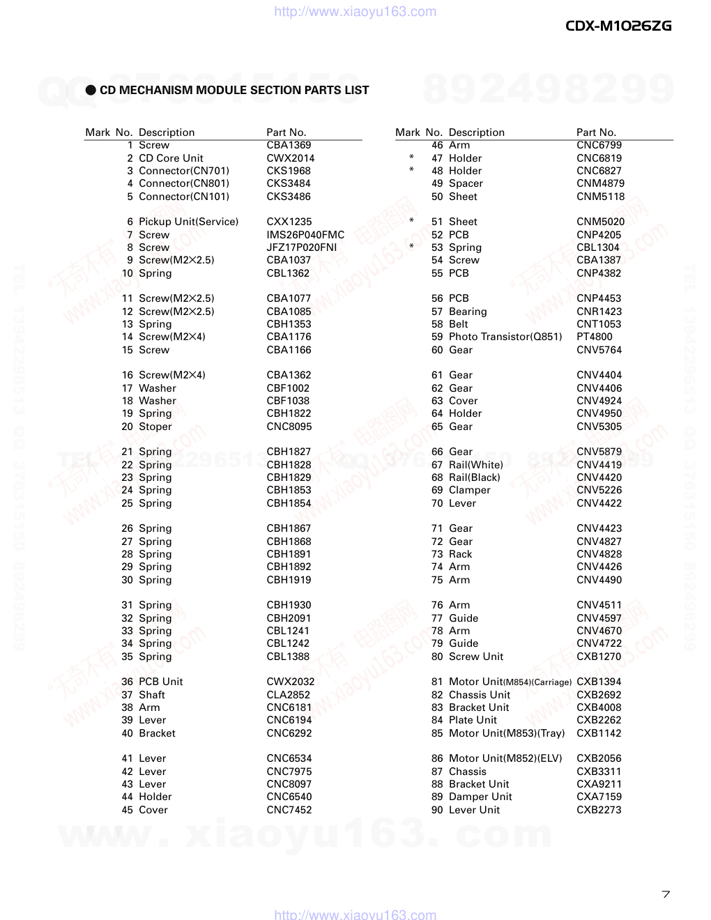
1 Screw
CBA1369
2 CD Core Unit
CWX2014
3 Connector(CN701)
CKS1968
4 Connector(CN801)
CKS3484
5 Connector(CN101)
CKS3486
6 Pickup Unit(Service)
CXX1235
7 Screw
IMS26P040FMC
8 Screw
JFZ17P020FNI
9 Screw(M2×2.5)
CBA1037
10 Spring
CBL1362
11 Screw(M2×2.5)
CBA1077
12 Screw(M2×2.5)
CBA1085
13 Spring
CBH1353
14 Screw(M2×4)
CBA1176
15 Screw
CBA1166
16 Screw(M2×4)
CBA1362
17 Washer
CBF1002
18 Washer
CBF1038
19 Spring
CBH1822
20 Stoper
CNC8095
21 Spring
CBH1827
22 Spring
CBH1828
23 Spring
CBH1829
24 Spring
CBH1853
25 Spring
CBH1854
26 Spring
CBH1867
27 Spring
CBH1868
28 Spring
CBH1891
29 Spring
CBH1892
30 Spring
CBH1919
31 Spring
CBH1930
32 Spring
CBH2091
33 Spring
CBL1241
34 Spring
CBL1242
35 Spring
CBL1388
36 PCB Unit
CWX2032
37 Shaft
CLA2852
38 Arm
CNC6181
39 Lever
CNC6194
40 Bracket
CNC6292
41 Lever
CNC6534
42 Lever
CNC7975
43 Lever
CNC8097
44 Holder
CNC6540
45 Cover
CNC7452
46 Arm
CNC6799
*
47 Holder
CNC6819
*
48 Holder
CNC6827
49 Spacer
CNM4879
50 Sheet
CNM5118
*
51 Sheet
CNM5020
52 PCB
CNP4205
*
53 Spring
CBL1304
54 Screw
CBA1387
55 PCB
CNP4382
56 PCB
CNP4453
57 Bearing
CNR1423
58 Belt
CNT1053
59 Photo Transistor(Q851)
PT4800
60 Gear
CNV5764
61 Gear
CNV4404
62 Gear
CNV4406
63 Cover
CNV4924
64 Holder
CNV4950
65 Gear
CNV5305
66 Gear
CNV5879
67 Rail(White)
CNV4419
68 Rail(Black)
CNV4420
69 Clamper
CNV5226
70 Lever
CNV4422
71 Gear
CNV4423
72 Gear
CNV4827
73 Rack
CNV4828
74 Arm
CNV4426
75 Arm
CNV4490
76 Arm
CNV4511
77 Guide
CNV4597
78 Arm
CNV4670
79 Guide
CNV4722
80 Screw Unit
CXB1270
81 Motor Unit(M854)(Carriage) CXB1394
82 Chassis Unit
CXB2692
83 Bracket Unit
CXB4008
84 Plate Unit
CXB2262
85 Motor Unit(M853)(Tray)
CXB1142
86 Motor Unit(M852)(ELV)
CXB2056
87 Chassis
CXB3311
88 Bracket Unit
CXA9211
89 Damper Unit
CXA7159
90 Lever Unit
CXB2273
Mark No. Description
Part No.
Mark No. Description
Part No.
- CD MECHANISM MODULE SECTION PARTS LIST
www. xiaoyu163. com
QQ 376315150
9
9
2
8
9
4
2
9
8
TEL 13942296513
9
9
2
8
9
4
2
9
8
0
5
1
5
1
3
6
7
3
Q
Q
TEL 13942296513 QQ 376315150 892498299
TEL 13942296513 QQ 376315150 892498299
http://www.xiaoyu163.com
8
CDX-M1026ZG
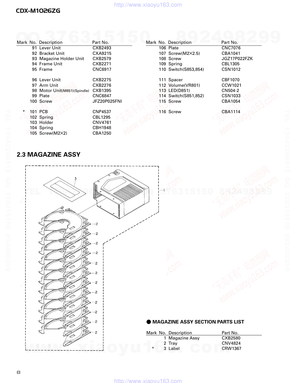
2.3 MAGAZINE ASSY
1 Magazine Assy
CXB2580
2 Tray
CNV4824
*
3 Label
CRW1367
- MAGAZINE ASSY SECTION PARTS LIST
Mark No. Description
Part No.
91 Lever Unit
CXB2493
92 Bracket Unit
CXA9215
93 Magazine Holder Unit
CXB2579
94 Frame Unit
CXB2271
95 Frame
CNC6917
96 Lever Unit
CXB2275
97 Arm Unit
CXB2276
98 Motor Unit(M851)(Spindle) CXB1395
99 Plate
CNC6847
100 Screw
JFZ20P025FNI
*
101 PCB
CNP4537
102 Spring
CBL1295
103 Holder
CNV4761
104 Spring
CBH1948
105 Screw(M2×2)
CBA1250
106 Plate
CNC7076
107 Screw(M2×2.5)
CBA1041
108 Screw
JGZ17P022FZK
109 Spring
CBL1305
110 Switch(S853,854)
CSN1012
111 Spacer
CBF1070
112 Volume(VR801)
CCW1021
113 LED(D851)
CN504-2
114 Switch(S851,852)
CSN1033
115 Screw
CBA1054
116 Screw
CBA1114
Mark No. Description
Part No.
Mark No. Description
Part No.
www. xiaoyu163. com
QQ 376315150
9
9
2
8
9
4
2
9
8
TEL 13942296513
9
9
2
8
9
4
2
9
8
0
5
1
5
1
3
6
7
3
Q
Q
TEL 13942296513 QQ 376315150 892498299
TEL 13942296513 QQ 376315150 892498299
http://www.xiaoyu163.com
9
CDX-M1026ZG
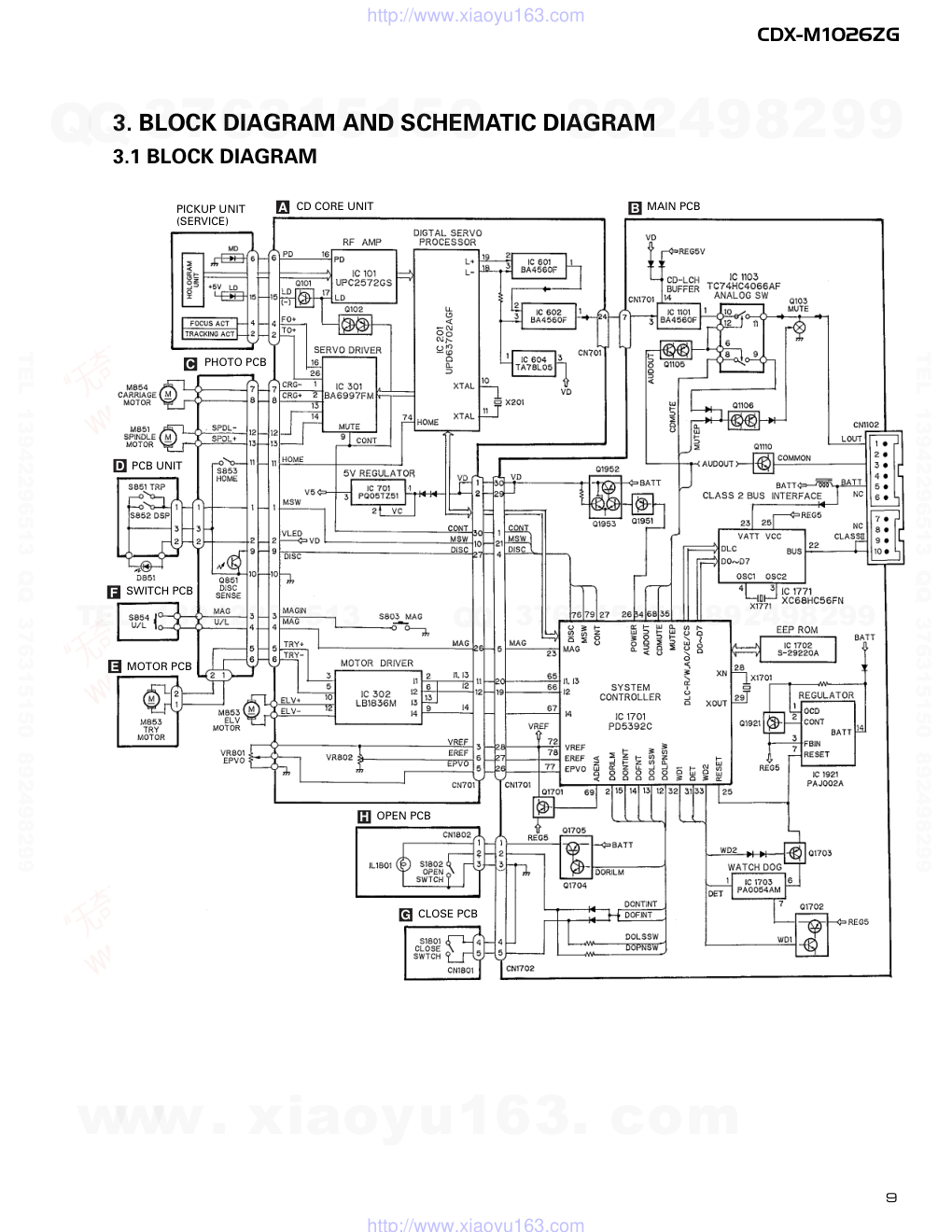
3. BLOCK DIAGRAM AND SCHEMATIC DIAGRAM
3.1 BLOCK DIAGRAM
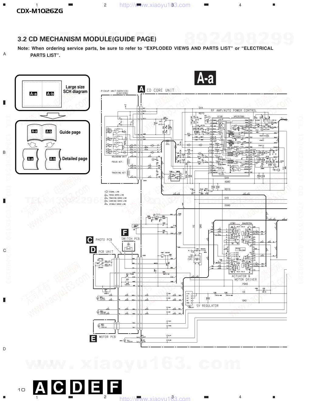
A
CD CORE UNIT
B MAIN PCB
D PCB UNIT
MOTOR PCB
E
PHOTO PCB
C
SWITCH PCB
F
PICKUP UNIT
(SERVICE)
OPEN PCB
H
CLOSE PCB
G
www. xiaoyu163. com
QQ 376315150
9
9
2
8
9
4
2
9
8
TEL 13942296513
9
9
2
8
9
4
2
9
8
0
5
1
5
1
3
6
7
3
Q
Q
TEL 13942296513 QQ 376315150 892498299
TEL 13942296513 QQ 376315150 892498299
http://www.xiaoyu163.com
10
CDX-M1026ZG
1
2
3
4
1
2
3
4
D
C
B
A
CCP1175
CXB1395
CXB1394
CXB1142
CXB2056
A C
A-a
D E
3.2 CD MECHANISM MODULE(GUIDE PAGE)
Note: When ordering service parts, be sure to refer to “EXPLODED VIEWS AND PARTS LIST” or “ELECTRICAL
PARTS LIST”.
A-a
A-b
A-a
A-a
A-b
A-b
A-b
A-b
A-a
A-a
Large size
SCH diagram
Guide page
Detailed page
F
A
E
D
C
F
www. xiaoyu163. com
QQ 376315150
9
9
2
8
9
4
2
9
8
TEL 13942296513
9
9
2
8
9
4
2
9
8
0
5
1
5
1
3
6
7
3
Q
Q
TEL 13942296513 QQ 376315150 892498299
TEL 13942296513 QQ 376315150 892498299
http://www.xiaoyu163.com
11
CDX-M1026ZG
5
6
7
8
5
6
7
8
D
C
B
A
C209 100P
R206
510
C302 R22
R301
3R3K
MAIN PCB
A-b
A
B
www. xiaoyu163. com
QQ 376315150
9
9
2
8
9
4
2
9
8
TEL 13942296513
9
9
2
8
9
4
2
9
8
0
5
1
5
1
3
6
7
3
Q
Q
TEL 13942296513 QQ 376315150 892498299
TEL 13942296513 QQ 376315150 892498299
http://www.xiaoyu163.com
12
CDX-M1026ZG
1
2
3
4
1
2
3
4
D
C
B
A
CCP1175
A-a
A-a A-b
A
www. xiaoyu163. com
QQ 376315150
9
9
2
8
9
4
2
9
8
TEL 13942296513
9
9
2
8
9
4
2
9
8
0
5
1
5
1
3
6
7
3
Q
Q
TEL 13942296513 QQ 376315150 892498299
TEL 13942296513 QQ 376315150 892498299
http://www.xiaoyu163.com
13
CDX-M1026ZG
5
6
7
8
5
6
7
8
D
C
B
A
CCP1175
CXB1395
CXB1394
CXB1142
CXB2056
A-a
A-a A-b
C D E F
E
D
C
F
www. xiaoyu163. com
QQ 376315150
9
9
2
8
9
4
2
9
8
TEL 13942296513
9
9
2
8
9
4
2
9
8
0
5
1
5
1
3
6
7
3
Q
Q
TEL 13942296513 QQ 376315150 892498299
TEL 13942296513 QQ 376315150 892498299
http://www.xiaoyu163.com
14
CDX-M1026ZG
1
2
3
4
1
2
3
4
D
C
B
A
A-b
A-a A-b
R206
510
C209
100P
www. xiaoyu163. com
QQ 376315150
9
9
2
8
9
4
2
9
8
TEL 13942296513
9
9
2
8
9
4
2
9
8
0
5
1
5
1
3
6
7
3
Q
Q
TEL 13942296513 QQ 376315150 892498299
TEL 13942296513 QQ 376315150 892498299
http://www.xiaoyu163.com
15
CDX-M1026ZG
5
6
7
8
5
6
7
D
C
B
A
A-b
A-a A-b
8
C302 R22
R302
3R3K
MAIN PCB
B
www. xiaoyu163. com
QQ 376315150
9
9
2
8
9
4
2
9
8
TEL 13942296513
9
9
2
8
9
4
2
9
8
0
5
1
5
1
3
6
7
3
Q
Q
TEL 13942296513 QQ 376315150 892498299
TEL 13942296513 QQ 376315150 892498299
http://www.xiaoyu163.com
16
CDX-M1026ZG
- Waveforms
1 RFO
0.5V/div. 0.5µs/div.
Normal mode: play
1 CH1: RFO
1V/div.
2 CH2: MIRR
5V/div.
Test mode: Tracking open
0.5ms/div
1 CH1: RFO
1V/div.
2 CH2: MIRR
5V/div.
Normal mode: The defect part
passes
0.5ms/div
3 CH1: FD
0.5V/div.
4 CH2: FOP
2V/div.
Test mode: No disc, Focus close
0.2s/div.
3 CH1: FD
0.5V/div.
5 CH2: FOK
2V/div.
Normal mode: Focus close
0.2s/div.
6 CH1: FEY
0.5V/div.
7 CH2: XSI
2V/div.
Normal mode: Focus close
1ms/div.
REFO →
8 CH1: TEY
0.5V/div.
9 CH2: TD
0.5V/div.
Test mode: 32 tracks jump (FWD)
0.5ms/div
8 CH1: TEY
0.5V/div.
9 CH2: TD
0.5V/div.
Test mode: Single jump (FWD)
0.5ms/div
8 CH1: TEY
0.5V/div.
9 CH2: TD
0.5V/div.
Test mode: 100 tracks jump (FWD)
5ms/div
6 CH1: FEY
0.1V/div.
3 CH2: FD
0.2V/div.
Normal mode: Play
20ms/div
3 CH1: FD
0.5V/div.
0 CH2: MDYA
1V/div.
Normal mode: Focus close (12cm)
0.5s/div.
3 CH1: FD
0.5V/div.
0 CH2: MDYA
1V/div.
Normal mode: Focus close (8cm)
0.5s/div.
GND →
GND →
REFO →
REFO →
REFO →
REFO →
GND →
REFO →
REFO →
GND →
REFO →
REFO →
REFO →
REFO →
REFO →
REFO →
REFO →
REFO →
REFO →
REFO →
REFO →
REFO →
Note:1. The encircled numbers denote measuring pointes in the circuit diagram.
2. Reference voltage
REFO:2.5V
www. xiaoyu163. com
QQ 376315150
9
9
2
8
9
4
2
9
8
TEL 13942296513
9
9
2
8
9
4
2
9
8
0
5
1
5
1
3
6
7
3
Q
Q
TEL 13942296513 QQ 376315150 892498299
TEL 13942296513 QQ 376315150 892498299
http://www.xiaoyu163.com
17
CDX-M1026ZG
8 CH1: TEY
0.2V/div.
9 CH2: TD
0.2V/div.
Normal mode: play
8 CH1: TEY
0.5V/div.
! CH2: SD
0.5V/div.
5ms/div.
0 MDYA
0.5V/div.
0.1s/div.
Normal mode: Play (12cm)
0 MDYA
0.5V/div.
10ms/div.
Long Search (12cm)
@ EFM
1V/div.
5µs/div.
Play
8 CH1: TEY
1V/div.
# CH2: TEC
1V/div.
Test mode: Focus close
Tracking open
2ms/div.
8 CH1: TEY
0.5V/div.
6 CH2: FEY
0.5V/div.
Normal mode: AGC after focus
0.2s/div.
20ms/div.
$ SCKO
2V/div.
1µs/div.
Play
% Dout
2V/div.
10µs/div.
Play
^ LRCK
2V/div.
20µs/div.
* CH1: R OUT
1V/div.
& CH2: L OUT
1V/div.
Normal mode: Play (1kHz 0dB)
6 CH1: FEY
0.2V/div.
3 CH2: FD
0.5V/div.
Normal mode: During AGC
1ms/div.
0.2ms/div.
REFO →
REFO →
REFO →
REFO →
REFO →
REFO →
GND →
REFO →
REFO →
REFO →
REFO →
REFO →
REFO →
REFO →
REFO →
REFO →
GND →
REFO →
GND →
REFO →
GND →
REFO →
www. xiaoyu163. com
QQ 376315150
9
9
2
8
9
4
2
9
8
TEL 13942296513
9
9
2
8
9
4
2
9
8
0
5
1
5
1
3
6
7
3
Q
Q
TEL 13942296513 QQ 376315150 892498299
TEL 13942296513 QQ 376315150 892498299
http://www.xiaoyu163.com
18
CDX-M1026ZG
8 CH1: TEY
0.2V/div.
9 CH2: TD
0.5V/div.
Normal mode: During AGC
1 CH1: RFO
1V/div.
^ CH2: HOLD
5V/div.
Normal mode: The defect part passes
800µm
1ms/div.
0.5ms/div
3 CH1: FD
1V/div.
^ CH2: HOLD
5V/div.
Normal mode: The defect part passes
800µm
0.5ms/div
GND →
GND →
REFO →
REFO →
REFO →
www. xiaoyu163. com
QQ 376315150
9
9
2
8
9
4
2
9
8
TEL 13942296513
9
9
2
8
9
4
2
9
8
0
5
1
5
1
3
6
7
3
Q
Q
TEL 13942296513 QQ 376315150 892498299
TEL 13942296513 QQ 376315150 892498299
http://www.xiaoyu163.com
19
CDX-M1026ZG
www. xiaoyu163. com
QQ 376315150
9
9
2
8
9
4
2
9
8
TEL 13942296513
9
9
2
8
9
4
2
9
8
0
5
1
5
1
3
6
7
3
Q
Q
TEL 13942296513 QQ 376315150 892498299
TEL 13942296513 QQ 376315150 892498299
http://www.xiaoyu163.com
20
CDX-M1026ZG
1
2
3
4
1
2
3
4
D
C
B
A
B
3.3 EXTENSION UNIT
B
MAIN PCB
A
CD CORE UNIT
www. xiaoyu163. com
QQ 376315150
9
9
2
8
9
4
2
9
8
TEL 13942296513
9
9
2
8
9
4
2
9
8
0
5
1
5
1
3
6
7
3
Q
Q
TEL 13942296513 QQ 376315150 892498299
TEL 13942296513 QQ 376315150 892498299
http://www.xiaoyu163.com
21
CDX-M1026ZG
5
6
7
8
5
6
7
8
D
C
B
A
C1106
R047/5R5
4.6V
G
CLOSE PCB
H
OPEN PCB
G
H
B
EXTENSION UNIT
Consists of
MAIN PCB
CLOSE PCB
OPEN PCB
6
7
8
9
10
1
5
2
3
4
CN1102
www. xiaoyu163. com
QQ 376315150
9
9
2
8
9
4
2
9
8
TEL 13942296513
9
9
2
8
9
4
2
9
8
0
5
1
5
1
3
6
7
3
Q
Q
TEL 13942296513 QQ 376315150 892498299
TEL 13942296513 QQ 376315150 892498299
http://www.xiaoyu163.com
22
CDX-M1026ZG
1
2
3
4
1
2
3
4
D
C
B
A
A
EPVO
EREF
E
F
REFO
CD CORE UNIT
A
PICKUP UNIT
(SERVICE)
CN1701
B
C
4. PCB CONNECTION DIAGRAM
4.1 CD CORE UNIT
NOTE FOR PCB DIAGRAMS
1. The parts mounted on this PCB
include all necessary parts for
several destination.
For further information for
respective destinations, be sure
to check with the schematic dia-
gram.
2. Viewpoint of PCB diagrams
Capacitor
Connector
P.C.Board
Chip Part
SIDE A
SIDE B
SIDE A
www. xiaoyu163. com
QQ 376315150
9
9
2
8
9
4
2
9
8
TEL 13942296513
9
9
2
8
9
4
2
9
8
0
5
1
5
1
3
6
7
3
Q
Q
TEL 13942296513 QQ 376315150 892498299
TEL 13942296513 QQ 376315150 892498299
http://www.xiaoyu163.com
23
CDX-M1026ZG
D
C
B
A
1
2
3
4
1
2
3
4A
SIDE B
MAG
CD CORE UNIT
A
www. xiaoyu163. com
QQ 376315150
9
9
2
8
9
4
2
9
8
TEL 13942296513
9
9
2
8
9
4
2
9
8
0
5
1
5
1
3
6
7
3
Q
Q
TEL 13942296513 QQ 376315150 892498299
TEL 13942296513 QQ 376315150 892498299
http://www.xiaoyu163.com
24
CDX-M1026ZG
1
2
3
4
1
2
3
4
D
C
B
A
SIDE A
B
4.2 MAIN PCB
MAIN PCB
B
CN701
A
CN1801
G
CN1802
H
www. xiaoyu163. com
QQ 376315150
9
9
2
8
9
4
2
9
8
TEL 13942296513
9
9
2
8
9
4
2
9
8
0
5
1
5
1
3
6
7
3
Q
Q
TEL 13942296513 QQ 376315150 892498299
TEL 13942296513 QQ 376315150 892498299
http://www.xiaoyu163.com
25
CDX-M1026ZG
D
C
B
A
1
2
3
4
1
2
3
4B
SIDE B
MAIN PCB
B
www. xiaoyu163. com
QQ 376315150
9
9
2
8
9
4
2
9
8
TEL 13942296513
9
9
2
8
9
4
2
9
8
0
5
1
5
1
3
6
7
3
Q
Q
TEL 13942296513 QQ 376315150 892498299
TEL 13942296513 QQ 376315150 892498299
http://www.xiaoyu163.com
26
CDX-M1026ZG
1
2
3
4
1
2
3
4
D
C
B
A
E
MOTOR PCB
E
C
4.5 MOTOR PCB
D
C
4.3 PHOTO PCB
1
5
10
13
1
2
3
M
SPINDLE
M851
2
1
M
CARRIAGE
M854
GY
YL
BL
BL
Q851
HOME
S853
A
CN801
F
E
D
PHOTO PCB
C
PCB UNIT
D
C
4.4 PCB UNIT
SIDE A
www. xiaoyu163. com
QQ 376315150
9
9
2
8
9
4
2
9
8
TEL 13942296513
9
9
2
8
9
4
2
9
8
0
5
1
5
1
3
6
7
3
Q
Q
TEL 13942296513 QQ 376315150 892498299
TEL 13942296513 QQ 376315150 892498299
http://www.xiaoyu163.com
27
CDX-M1026ZG
D
C
B
A
1
2
3
4
1
2
3
4
SWITCH PCB
F
C
4.6 SWITCH PCB
F
4.7 CLOSE PCB
4.8 OPEN PCB
CLOSE
OPEN
IL1801
CLOSE PCB
G
OPEN PCB
H
OPEN PCB
H
SIDE A
SIDE B
B CN1702
B CN1702
G H
www. xiaoyu163. com
QQ 376315150
9
9
2
8
9
4
2
9
8
TEL 13942296513
9
9
2
8
9
4
2
9
8
0
5
1
5
1
3
6
7
3
Q
Q
TEL 13942296513 QQ 376315150 892498299
TEL 13942296513 QQ 376315150 892498299
http://www.xiaoyu163.com
Unit Number : CWX2014
Unit Name
: CD Core Unit
CAPACITORS
IC
101
IC
UPC2572GS
IC
201
IC
UPD63702AGF
IC
301
IC
BA6997FM
IC
302
IC
LB1836M
IC
601
IC
BA4560F
IC
602
IC
BA4560F
IC
604
IC
TA78L05F
IC
701
IC
PQ05TZ51
Q
101
Transistor
2SD1664
Q
102
Transistor
UMD2N
D
701
Diode
1SR154-400
D
702
Diode
1SR154-400
X
201
Ceramic Resonator 16.93MHz
CSS1363
S
803
Switch(MAG)
CSN1028
VR
802
Semi-fixed 1kΩ(B)
CCP1175
RESISTORS
R
101
RS1/8S100J
R
102
RS1/8S120J
R
103
RS1/16S102J
R
104
RS1/16S822J
R
105
RS1/16S682J
R
106
RS1/16S183J
R
107
RS1/16S822J
R
108
RS1/16S333J
R
109
RS1/16S683J
R
110
RS1/16S134J
R
111
RS1/16S273J
R
113
RS1/16S222J
R
114
RS1/16S103J
R
115
RS1/16S103J
R
116
RS1/16S102J
R
117
RS1/16S163J
R
118
RS1/16S163J
R
201
RS1/16S104J
R
202
RS1/16S104J
R
203
RS1/16S0R0J
R
206
RS1/16S511J
R
301
RA4C332J
R
504
RS1/16S511J
R
505
RS1/16S101J
R
506
RA3C101J
R
511
RS1/16S102J
R
601
RS1/16S103J
R
602
RS1/16S103J
R
603
RS1/16S103J
R
604
RS1/16S103J
R
605
RS1/16S912J
R
606
RS1/16S912J
R
607
RS1/16S912J
R
608
RS1/16S912J
R
609
RS1/16S153J
R
610
RS1/16S153J
R
611
RN1/16SE1502D
R
612
RN1/16SE1502D
R
613
RN1/16SK5601D
R
614
RN1/16SK5601D
R
615
RN1/16SK5601D
R
616
RN1/16SK5601D
R
617
RS1/16S562J
R
618
RS1/16S562J
R
619
RS1/16S101J
R
620
RS1/16S101J
R
801
RS1/10S681J
R
804
RS1/16S622J
R
805
RS1/16S562J
R
807
RS1/16S203J
CAPACITORS
C
101
CEV101M6R3
C
102
CKSQYB104K16
C
103
CEV470M6R3
C
104
CKSQYB334K16
C
105
CCSRCH330J50
C
106
CKSRYB103K25
C
107
CEV4R7M35
C
108
CKSQYB273K25
C
109
CCSRCH101J50
C
110
CKSQYB104K16
C
111
CKSRYB332K50
C
112
CKSQYB473K25
C
113
CKSRYB103K25
C
114
CKSRYB391K50
C
115
CCSRCH121J50
C
116
CKSRYB682K50
C
117
CKSQYB333K25
C
118
CKSQYB334K16
C
119
CKSQYB334K16
C
120
CKSQYB224K16
C
121
CKSQYB224K16
C
122
CKSQYB104K16
C
123
CKSRYB472K50
C
124
CKSQYB104K16
C
125
CCSRCH6R0D50
C
126
CKSRYB153K25
C
201
CKSQYB334K16
C
202
CKSQYB104K16
C
205
CEV101M6R3
C
206
CKSQYB224K16
28
CDX-M1026ZG
5. ELECTRICAL PARTS LIST
NOTES:
- Parts whose parts numbers are omitted are subject to being not supplied.
- The part numbers shown below indicate chip components.
Chip Resistor
RS1/_S___J,RS1/__S___J
Chip Capacitor (except for CQS.....)
CKS....., CCS....., CSZS.....
=====Circuit Symbol and No.===Part Name
Part No.
---
------
------------------------------------------
-------------------------
=====Circuit Symbol and No.===Part Name
Part No.
---
------
------------------------------------------
-------------------------
A
www. xiaoyu163. com
QQ 376315150
9
9
2
8
9
4
2
9
8
TEL 13942296513
9
9
2
8
9
4
2
9
8
0
5
1
5
1
3
6
7
3
Q
Q
TEL 13942296513 QQ 376315150 892498299
TEL 13942296513 QQ 376315150 892498299
http://www.xiaoyu163.com
C
207
CKSRYB102K50
C
208
CKSQYB224K16
C
209
CCSRCH101J50
C
301
CEV101M10
C
302
CKSQYB224K16
C
601
CCSRCH181J50
C
602
CCSRCH181J50
C
603
CCSRCH820J50
C
604
CCSRCH820J50
C
605
CCSRCH820J50
C
606
CCSRCH820J50
C
607
CKSRYB222K50
C
608
CKSRYB222K50
C
609
CCSRCH331J50
C
610
CCSRCH331J50
C
611
CKSQYB104K16
C
612
CKSQYB104K16
C
613
CKSQYB104K16
C
614
CKSQYB104K16
C
615
CEV101M10
C
701
22µF/6.3V
CCH1233
C
702
CKSQYB334K16
C
703
CEV101M6R3
C
801
CKSRYB103K25
C
802
CKSQYB104K16
Extension Unit
Consists of
Main PCB
Close PCB
Open PCB
Unit Number :
HWX2034
Unit Name
:
Extension Unit
MISCELLANEOUS
IC
1101
IC
BA4560F
IC
1103
IC
TC74HC4066AF
IC
1701
IC
PD5392C
IC
1702
IC
S-29220A
IC
1703
IC
PA0054AM
IC
1771
IC
XC68HC56FN
IC
1921
IC
PAJ002A
Q
103
Transistor
DTC323TK
Q
104
Transistor
DTC323TK
Q
1105
Transistor
IMD3A
Q
1106
Transistor
IMD3A
Q
1110
Transistor
2SD1048
Q
1701
Transistor
DTA124EK
Q
1702
Transistor
IMD3A
Q
1703
Transistor
2SD601A
Q
1704
Transistor
2SC4116
Q
1705
Transistor
2SB1242
Q
1921
Transistor
2SB1184F5
Q
1951
Transistor
DTA124EK
Q
1952
Transistor
2SB1335A
Q
1953
Transistor
FMW1
D
1101
Diode
RD4R7M(B1)
D
1102
Chip Diode
MA151WK
D
1103
Chip Diode
MA151WK
D
1105
Chip Diode
MA151WA
D
1701
Diode
MA157A
D
1702
Chip Diode
MA151WA
D
1771
Diode
MA3180(M)
D
1772
Diode
MA3180(M)
D
1901
Diode
SM-3-02
D
1902
Diode
ERA15-02
D
1903
Diode
ERA15-02
L
101
Inductor
LCTB6R8K3216
L
102
Inductor
LCTB6R8K3216
L
1102
Inductor
LCTB6R8K3216
L
1701
Inductor
LCTB1R0K3216
L
1771
Inductor
CTF1418
L
1772
Inductor
LCTB1R0K2125
L
1901
Choke Coil 1.4mH
CTH1129
X
1701
Radiator 6.290MHz
CSS1451
X
1771
Radiator 4.00MHz
CSS1320
S
1801
Switch(CLOSE)
CSN1031
S
1802
Switch(OPEN)
CSN1031
IL
1801
Lamp 14V 65mA
CEL1350
EF
101
CCG1067
EF
102
CCG1067
EF 1102
CCG1067
RESISTORS
R
107
RS1/10S104J
R
108
RS1/10S104J
R
109
RS1/10S0R0J
R
110
RS1/10S0R0J
R
111
RS1/10S0R0J
R
112
RS1/10S0R0J
R
113
RS1/8S151J
R
114
RS1/8S151J
R
117
RS1/10S164J
R
118
RS1/10S164J
R
1109
RS1/10S102J
R
1110
RS1/10S224J
R
1111
RS1/10S224J
R
1113
RS1/10S105J
R
1114
RS1/10S105J
R
1115
RS1/10S103J
R
1119
RS1/10S154J
R
1120
RS1/10S103J
R
1121
RS1/10S103J
R
1122
RS1/10S102J
R
1701
RS1/10S103J
R
1702
RS1/10S433J
R
1703
RA3C222J
R
1706
RS1/10S222J
R
1708
RS1/10S104J
R
1709
RS1/10S102J
R
1710
RS1/10S472J
R
1712
RS1/10S104J
R
1714
RS1/10S513J
R
1715
RS1/10S103J
R
1718
RS1/10S823J
R
1719
RS1/10S222J
R
1721
RS1/10S104J
R
1722
RS1/10S473J
R
1723
RS1/10S222J
R
1725
RS1/10S511J
R
1726
RS1/10S101J
R
1727
RS1/10S105J
R
1728
RS1/10S474J
R
1729
RS1/10S105J
R
1730
RS1/10S222J
R
1731
RS1/10S222J
R
1732
RS1/10S473J
R
1733
RA4C102J
R
1734
RS1/10S103J
R
1736
RS1/10S473J
R
1737
RS1/10S102J
R
1738
RS1/10S473J
R
1739
RS1/8S562J
R
1740
RS1/10S473J
R
1741
RS1/10S104J
R
1742
RS1/10S474J
R
1743
RS1/10S473J
R
1744
RS1/10S473J
R
1753
RS1/10S101J
29
CDX-M1026ZG
=====Circuit Symbol and No.===Part Name
Part No.
---
------
------------------------------------------
-------------------------
=====Circuit Symbol and No.===Part Name
Part No.
---
------
------------------------------------------
-------------------------
B G H
www. xiaoyu163. com
QQ 376315150
9
9
2
8
9
4
2
9
8
TEL 13942296513
9
9
2
8
9
4
2
9
8
0
5
1
5
1
3
6
7
3
Q
Q
TEL 13942296513 QQ 376315150 892498299
TEL 13942296513 QQ 376315150 892498299
http://www.xiaoyu163.com
R
1754
RS1/10S101J
R
1755
RS1/10S511J
R
1756
RS1/10S101J
R
1771
RS1/10S103J
R
1772
RS1/10S103J
R
1773
RS1/10S512J
R
1774
RS1/10S333J
R
1775
RN1/10SE2402D
R
1776
RN1/10SE3002D
R
1777
RS1/10S3R3J
R
1778
RN1/10SE1601D
R
1779
RN1/10SE9100D
R
1780
RS1/10S562J
R
1921
RS1/10S103J
R
1923
RS1/8S3R9J
R
1924
RS1/10S102J
R
1925
RS1/10S105J
R
1926
RS1/10S104J
R
1927
RS1/10S514J
R
1928
RS1/10S103J
R
1929
RS1/10S103J
R
1951
RS1/10S101J
R
1952
RS1/10S223J
R
1953
RS1/8S121J
R
1954
RS1/8S101J
R
1955
RS1/10S471J
R
1956
RS1/10S681J
CAPACITORS
C
103
CEJA100M16
C
104
CEJA100M16
C
109
CEJA220M16
C
110
CEJA220M16
C
111
CEJA220M16
C
112
CEJA220M16
C
1106
0.047µF/5.5V
CCL1015
C
1108
CSZSC220M6R3
C
1109
CKSQYB103K50
C
1111
CEJA220M16
C
1113
CKSQYB103K50
C
1118
CKSQYB103K50
C
1120
CKSQYB103K50
C
1701
CKSQYB224K16
C
1702
CKSQYB103K50
C
1703
CKSQYB473K25
C
1704
CKSQYB473K25
C
1705
CKSQYB103K50
C
1706
CKSQYB102K50
C
1707
CKSQYB102K50
C
1708
CKSQYB102K50
C
1709
CKSQYB103K50
C
1710
CEAL2R2M50
C
1711
CKSQYB103K50
C
1712
CKSQYB103K50
C
1713
CKSQYB103K50
C
1714
CKSQYB103K50
C
1715
CCSQCH561J50
C
1716
CCSQCH561J50
C
1717
CCSQCH561J50
C
1718
CCSQCH561J50
C
1719
CCSQCH561J50
C
1720
CCSQCH561J50
C
1721
CCSQCH561J50
C
1722
CCSQCH561J50
C
1723
CCSQCH101J50
C
1724
CCSQCH101J50
C
1725
CCSQCH101J50
C
1726
CCSQCH101J50
C
1771
CKSQYB104K25
C
1772
CKSQYB104K50
C
1773
CKSQYB104K25
C
1774
CCSQCH471J50
C
1775
CCSQCH101J50
C
1776
CCSQCH561J50
C
1777
CCSQCH561J50
C
1778
CCSQCH561J50
C
1901
470µF/16V
CCH1080
C
1902
CKSQYB102K50
C
1903
CKSQYB222K50
C
1904
470µF/16V
CCH1080
C
1905
470µF/16V
CCH1080
C
1921
CKSQYB103K50
C
1923
CKSQYB103K50
C
1924
CKSQYB103K50
C
1925
CSZA220M10
C
1951
CKSQYB473K25
C
1952
CEJA101M10
C
1953
CKSQYB103K50
Unit Number :
Unit Name
:
Photo PCB
Q
851
Photo-transistor
PT4800
S
853
Switch
CSN1012
Unit Number :
Unit Name
:
PCB Unit
S
851
Switch(TRP)
CSN1033
S
852
Switch(DSP)
CSN1033
R
851
RS1/8S473J
R
852
RS1/8S753J
Unit Number :
Unit Name
:
Motor PCB
M
853
Motor Unit(TRAY)
CXB1142
Unit Number :
Unit Name
:
Switch PCB
S
854
Switch(U/L)
CSN1012
Miscellaneous Parts List
D
851
LED
CN504-2
M
851
Motor Unit(SPINDLE)
CXB1395
M
852
Motor Unit(ELV)
CXB2056
M
854
Motor Unit(CARRIAGE)
CXB1394
VR
801
Volume 10kΩ
CCW1021
Pickup Unit(Service)
CXX1235
30
CDX-M1026ZG
=====Circuit Symbol and No.===Part Name
Part No.
---
------
------------------------------------------
-------------------------
=====Circuit Symbol and No.===Part Name
Part No.
---
------
------------------------------------------
-------------------------
C
E
D
F
www. xiaoyu163. com
QQ 376315150
9
9
2
8
9
4
2
9
8
TEL 13942296513
9
9
2
8
9
4
2
9
8
0
5
1
5
1
3
6
7
3
Q
Q
TEL 13942296513 QQ 376315150 892498299
TEL 13942296513 QQ 376315150 892498299
http://www.xiaoyu163.com
31
CDX-M1026ZG
6. ADJUSTMENT
6.1 CONNECTION DIAGRAM
CMD. BOX(CEP-323)
DC Regulated
Power Supply
CDX-M1026ZG/X1H/UC
Extension Cable(CDN-960)
DC 9–16V
www. xiaoyu163. com
QQ 376315150
9
9
2
8
9
4
2
9
8
TEL 13942296513
9
9
2
8
9
4
2
9
8
0
5
1
5
1
3
6
7
3
Q
Q
TEL 13942296513 QQ 376315150 892498299
TEL 13942296513 QQ 376315150 892498299
http://www.xiaoyu163.com
32
CDX-M1026ZG
6.2 CD ADJUSTMENT
1)Precautions
• This unit uses a single power supply (+5V) for the reg-
ulator. The signal reference potential, therefore, is
connected to REFO(approx. 2.5V) instead of GND.
If REFO and GND are connected to each other by mis-
take during adjustments,not only will it be impossible
to measure the potential correctly,but the servo will
malfunction and a severe shock will be applied to the
pick-up. To avoid this,take special note of the follow-
ing.
• Do not connect the negative probe of the measuring
equipment to REFO and GND together. It is especially
important not to connect the channel 1 negative
probe of the oscilloscope to REFO with the channel 2
negative probe connected to GND.
Since the frame of the measuring instrument is usual-
ly at the same potential as the negative probe,change
the frame of the measuring instrument to floating sta-
tus.
If by accident REFO comes in contact with
GND,immediately switch the regulator or power OFF.
• Always make sure the regulator is OFF when connect-
ing and disconnecting the various filters and wiring
required for measurements.
• Before proceeding to further adjustments and mea-
surements after switching regulator ON,let the player
run for about one minute to allow the circuits to sta-
bilize.
• Since the protective systems in the unit’s software are
rendered inoperative in test mode,be very careful to
avoid mechanical and /or electrical shocks to the sys-
tem when making adjustment.
• This unit is adjusted in a combination with the CD con-
troller tool(CEP-323). Each regulator key should be
operated at the unit.
With the CEP-323 taken up for reference, a descrip-
tion will be given below concerning how to enter into
the test mode, including key operations. The key in
the adjustment text is also one of the CEP-323 keys.
• How to enter into the test mode
1. Setup the POWER switch ON and PMM switch
RUN of CEP-323.
2. DC Regulated Power Supply power ON.
3. Pressing the RESET switch of CEP-323.
4. Wait for 10 seconds.
5. Pressing the TESTIN switch of CEP-323.
6. Insert the magazine assy.
• Resetting the test mode
DC Regulated Power Supply power OFF.
• Disc detection during loading and eject operations is
performed by means of a photo transistor in this
unit.Consequently,if the inside of the unit is exposed
to a strong light source when the outer casing is
removed for repairs or adjustment,the following mal-
functions may occur.
*During PLAY, even if the eject button is pressed,the
disc will not be ejected and the unit will remain in
the PLAY mode.
*The unit will not load a disc.
When the unit malfunctions this way,either re-posi-
tion the light source,move the unit or cover the
photo transistor.
• When loading and unloading discs during adjustment
procedures,always wait for the disc to be properly
clamped or ejected before pressing another key.
Otherwise, there is a risk of the actuator being
destroyed.
• Turn power off when pressing the button TR+ or the
button TR- key for focus search in the test mode. (Or
else lens may stick and the actuator may be dam-
aged.)
• SINGLE/4TRK/10TRK/32TRK will continue to operate
even after the key is released.Tracking is closed the
moment C-MOVE is released.
• JUMP MODE resets to SINGLE as soon as power is
switched off.
www. xiaoyu163. com
QQ 376315150
9
9
2
8
9
4
2
9
8
TEL 13942296513
9
9
2
8
9
4
2
9
8
0
5
1
5
1
3
6
7
3
Q
Q
TEL 13942296513 QQ 376315150 892498299
TEL 13942296513 QQ 376315150 892498299
http://www.xiaoyu163.com
33
CDX-M1026ZG
•Note :
Unlike previous CD mechanism modules the grating angle of the pickup unit cannot be adjusted after the pickup
unit is changed. The pickup unit in the CD mechanism module is adjusted on the production line to match the CD
mechanism module and is thus the best adjusted pickup unit for the CD mechanism module. Changing the pickup
unit is thus best considered as a last resort. However, if the pickup unit must be changed, the grating should be
checked using the procedure below.
•Purpose :
To check that the grating is within an acceptable range.
•Symptoms of Mal-adjustment :
If the grating is off by a large amount symptoms such as being unable to close tracking, being unable to perform
track search operations, or track searching taking a long time, may appear.
•Method :
•Measuring Equipment
•Oscilloscope, Two L.P.F.
•Measuring Points
•E, F, REFOUT
•Disc
•ABEX TCD-784
•Mode
•TEST MODE
•Checking Procedure
1. In test mode, load the disc and switch the 5V regulator on.
2. Using the TR+ and TR- buttons, move the pickup unit to the innermost track.
3. Press key 5 to close focus, the display should read "91". Press key 4 to implement the tracking balance adjust-
ment the display should now read "81". Press key 5 4 times. The display will change, returning to "81" on the
fourth press.
4. As shown in the diagram above, monitor the LPF outputs using the oscilloscope and check that the phase differ-
ence is within 75° . Refer to the photographs supplied to determine the phase angle.
5. If the phase difference is determined to be greater than 75° try changing the pickup unit to see if there is any
improvement. If, after trying this a number of times, the grating angle does not become less than 75° then the
mechanism should be judged to be at fault.
•Note
Because of eccentricity in the disc and a slight misalignment of the clamping center the grating waveform may be
seen to "wobble" ( the phase difference changes as the disc rotates). The angle specified above indicates the aver-
age angle.
•Hint
Reloading the disc changes the clamp position and may decrease the "wobble".
6.3 CHECKING THE GRATING
- Checking the Grating After Changing the Pickup Unit
REFO
E
F
REFO
REFO
E
F
L.P.F.
L.P.F.
CD CORE UNIT
Xch
Ych
Oscilloscope
100kW
100kW
390pF
390pF
www. xiaoyu163. com
QQ 376315150
9
9
2
8
9
4
2
9
8
TEL 13942296513
9
9
2
8
9
4
2
9
8
0
5
1
5
1
3
6
7
3
Q
Q
TEL 13942296513 QQ 376315150 892498299
TEL 13942296513 QQ 376315150 892498299
http://www.xiaoyu163.com
34
CDX-M1026ZG
Grating waveform
45°
0°
75°
60°
30°
90°
Ech t Xch 20mV/div, AC
Fch t Ych 20mV/div, AC
www. xiaoyu163. com
QQ 376315150
9
9
2
8
9
4
2
9
8
TEL 13942296513
9
9
2
8
9
4
2
9
8
0
5
1
5
1
3
6
7
3
Q
Q
TEL 13942296513 QQ 376315150 892498299
TEL 13942296513 QQ 376315150 892498299
http://www.xiaoyu163.com
35
CDX-M1026ZG
•Note :
Unlike the conventional mechanisms, the new mechanism detects the height of the stage using slide-variable
resistance.
To absorb dislocation of the stage height caused by differences in the mechanism and the CD core unit, adjust-
ment must be made for each CD-mechanism module using a variable resistor.
Normally, readjustment is not needed, as this has been adjusted at the factory. However, adjustment of elevation
is required according to the procedure explained below if an elevation error has occurred or if the CD core unit
has been removed.
•Purpose :
To adjust and confirm whether or not elevation operates correctly.
•Adjustment Method :
•Measuring Equipment:
Millivoltmeter
•Measuring Points :
EREF, EPVO
•Setting :
Without a magazine in Test mode
With the mechanism placed upside-down (Place the CD mechanism module so that the
CD core unit is above.)
•Confirmation Procedure
1.
Press key 10 enter Test mode, then select Multi-CD player.
2. Press key 3 to enter Mechanism Test mode.
3.
Press key 8 twice to specify the amount of movement.
6.4 ADJUSTMENT OF ELEVATION WHEN THE CD CORE UNIT HAS BEEN REMOVED
FOR MAINTENANCE
'
"
72
00' 00"
EREF
EPVO
mV meter
CD CORE UNIT
Examples of display
72
00' 02"
72
00' 01"
The amount of movement
changes each time key 8 is
pressed.
maximum movement
i
Key 8
i
during movement
i
Key 8
i
minimum movement
72
00' 00"
i
i
Key 8
www. xiaoyu163. com
QQ 376315150
9
9
2
8
9
4
2
9
8
TEL 13942296513
9
9
2
8
9
4
2
9
8
0
5
1
5
1
3
6
7
3
Q
Q
TEL 13942296513 QQ 376315150 892498299
TEL 13942296513 QQ 376315150 892498299
http://www.xiaoyu163.com
36
CDX-M1026ZG
4.
Press key 5 to set ELV/TRAY mode to TRAY.
5.
Press key TR+ to release the clamp and return the tray to the magazine.
6.
Press key 5 to enter Elevation Move mode.
7.
Use key TR+/TR- to operate elevation and set if to the lower stage (seventh to
twelfth discs) so that elevation is set to the "R" mark (Fig. 1).
8.
Make the adjustment.
Use VR802 to adjust the difference in potential between EREF and EPVO to 0 ±20
mV.
9.
When adjustment is completed, press key 1 to exit Mechanism Test mode.
10. Confirm operation of the mechanism.
Place the mechanism horizontally (CD core unit below). Take care not to short-cir-
cuit the PCB.
11. Confirm the height of the stage. Use the 10 key to select Disc No.10.
Check if the stopper bend of the clamp lever is engaged in the groove of the frame
stopper (Fig. 2-3).
•Note :
The stopper bend will be pressed downward into the groove for final clamping. Confirm the engagement position
of the stopper bend.
•If the stopper bend is engaged in the center and pressed downward, adjustment is completed. Go to step 15.
•If the stopper bend is dislocated, check the amount of dislocation by following steps 12 to 14.
72
00' 02"
72
00' 02"
'
"
04
00' 00"
Examples of display
72
01' 02"
Release the clamp
www. xiaoyu163. com
QQ 376315150
9
9
2
8
9
4
2
9
8
TEL 13942296513
9
9
2
8
9
4
2
9
8
0
5
1
5
1
3
6
7
3
Q
Q
TEL 13942296513 QQ 376315150 892498299
TEL 13942296513 QQ 376315150 892498299
http://www.xiaoyu163.com
37
CDX-M1026ZG
12. To see the amount of dislocation, place the mechanism upside-down.
If the stopper bend has been dislocated in the direction of the sev-
enth CD, turn VR802 to the left(Fig. 2).
To lower the stage toward the twelfth step by 0.1 mm, reduce the
voltage of EREF (adjusted in step 8) by 20 mV.
If the stopper bend has been dislocated in the direction of the twelfth
CD, turn VR802 to the right(Fig. 4).
To raise the stage toward the seventh step by 0.1 mm, increase the
voltage of EREF (adjusted in step 8) by 20 mV.
13. Place the mechanism horizontal. Go back to step 11 to reconfirm the
stage height.
14. When adjustment of the stage height is completed, proceed as fol-
lows:
15. Open the door and then eject the magazine assy.
16. Once operation of the mechanism has stopped, turn the power OFF.
17. Wait more than one minute after the power is turned off, then turn the power ON and insert a magazine.
18. Check if the mechanism operates correctly with the first, sixth, seventh and twelfth CDs.
19. If the mechanism operates properly, adjustment is completed. If the mechanism operates improperly, make the
adjustment again.
GND
EREF
VR802
mV meter
www. xiaoyu163. com
QQ 376315150
9
9
2
8
9
4
2
9
8
TEL 13942296513
9
9
2
8
9
4
2
9
8
0
5
1
5
1
3
6
7
3
Q
Q
TEL 13942296513 QQ 376315150 892498299
TEL 13942296513 QQ 376315150 892498299
http://www.xiaoyu163.com
38
CDX-M1026ZG
R
Adjust to the graduation of the R mark.
NG
Stopper bend of the
clamp lever
Frame stopper
OK
Engaged in the center and pressed downward.
NG
Dislocated toward the twelfth CD.
Dislocated toward the seventh CD.
Fig. 1
Fig. 2
Fig. 3
Fig. 4
www. xiaoyu163. com
QQ 376315150
9
9
2
8
9
4
2
9
8
TEL 13942296513
9
9
2
8
9
4
2
9
8
0
5
1
5
1
3
6
7
3
Q
Q
TEL 13942296513 QQ 376315150 892498299
TEL 13942296513 QQ 376315150 892498299
http://www.xiaoyu163.com
39
CDX-M1026ZG
- Pin Functions (PD5392C)
Pin No.
Pin Name
I/O
Format
Function and Operation
1
VDIN
I
Power supply short sensor input
2
DORILM
O
Eject door illumination output
3–5
NC
Not used
6
XA0
O
C
Control signal distinguishing data from microcomputer
7
XSCK
I/O
C
LSI clock input/output
8
XSO
O
C
LSI data output
9
XSI
I
LSI data input
10
xstb
I
CD LSI strobe output
11
xrst
O
C
CD LSI reset output
12
dopnsw
I
Door open switch input
13
dclssw
I
Door close switch input
14
DOFINT
I
Not used
15
DONINT
I
Not used
16
NC
Not used
17
dce
O
C
Not used
18
ECE
O
C
Chip select output for EEPROM
19
ECK
O
C
Serial clock output for EEPROM
20
EDO
O
C
Serial data output for EEPROM
21
EDI
I
Serial data input from EEPROM
22
dlcint
I
Class 2 bus interrupt input from IC1771
23
mag
I
Magazine lock switch input
24
CNVSS
GND
25
reset
I
Reset input
26
power
O
C
CD +5V control
27
CONT
O
C
CD servo driver power control output
28
XIN
I
Crystal oscillating element connection pin
29
XOUT
O
Crystal oscillating element connection pin
30
VSS
GND
31
DET
I/O
C
Watch dog IC interface input/output
32
WD1
I/O
C
Watch dog IC interface input/output
33
WD2
I/O
C
Watch dog IC interface input/output
34
AUDOUT
O
C
Not used
35
MUTEP
O
C
Not used
36–41
NC
Not used
42
dlcrst
O
C
Class 2 bus interface output for IC1771
43
dlccs
O
C
Class 2 bus interface output for IC1771
44
DLCCE
O
C
Class 2 bus interface output for IC1771
45
DLCA0
O
C
Class 2 bus interface output for IC1771
46
DLCR/w
O
C
Class 2 bus interface output for IC1771
47–54
D7-D0
I/O
C
Class 2 bus interface input/output for IC1771
55
NC
Not used
56
^/12
I
6/12 switching input
57
NC
Not used
58
MIRR
I
CD mirror detection input
59
LOCK
I
CD spindle lock input
60
FOK
I
CD FOK signal input
61
csel
I
Compression select
62–64
NC
Not used
65
I1,3
O
C
Motor driver control output
66
I2
O
C
Motor driver control output
67
I4
O
C
Motor driver control output
68
CDMUTE
O
C
CD mute control output
69
adena
O
C
A/D reference voltage output
70
testin
I
Test program mode input
71
VCC
Power supply
7. GENERAL INFORMATION
7.1 IC
www. xiaoyu163. com
QQ 376315150
9
9
2
8
9
4
2
9
8
TEL 13942296513
9
9
2
8
9
4
2
9
8
0
5
1
5
1
3
6
7
3
Q
Q
TEL 13942296513 QQ 376315150 892498299
TEL 13942296513 QQ 376315150 892498299
http://www.xiaoyu163.com
40
CDX-M1026ZG
Pin No.
Pin Name
I/O
Format
Function and Operation
72
VREF
I
A/D converter reference voltage input
73
AVSS
(A/D converter GND)
74
BSENS
I
Back up sense input
75
U/l
I
ELV position switch input
76
DISK
Disc detector and 8/12cm detect
77
EPVO
I
Slide voltage input for ELV detector
78
EREF
I
ELV reference voltage input
79
MSW
I
Disc detect timing and tray position input
80
TEMP
I
Not used
*PD5392C
24
25
40
41
64
65
80
1
Format
Meaning
C
C MOS
- Pin Functions (XC68HC56FN)
Pin No.
Pin Name
I/O
Function and Operation
1
VSSA
Analog ground terminal
2
LOTI
I/O
Logic out transceiver input/output
3
OSC2
O
External reference connection output
4
OSC1
I
External clock connection input
5
dlcrst
I
DLCP reset signal input
6
dlccs
I
DCLP chip select signal input
7
DLCCE
I
DCLP chip enable signal input
8
DLCA0
I
Address select signal input
9
DLCR/w
I
DLCP data transfer control input
10
dlcint
O
DCLP interrupt request input
11
VDD
Digital power supply terminal
12–19
D7-D0
I/O
Bidirectional three-state data bus input output
20
VSSD
Digital ground terminal
21
LOAD
I
External bus load connection input
22
BUS
I/O
Serial data signal input/output
23
VBATT
Transceiver power supply terminal
24
PSEN
O
Power supply status signal output
25
VCC
Analog power supply terminal
26
REXT2
I
Transceiver biasing resistor input
27
REXT1
I
Transceiver biasing resistor input
28
LITO
I/O
Logic in transceiver input/output
*XC68HC56FN
IC's marked by* are MOS type.
Be careful in handling them because they are very
liable to be damaged by electrostatic induction.
www. xiaoyu163. com
QQ 376315150
9
9
2
8
9
4
2
9
8
TEL 13942296513
9
9
2
8
9
4
2
9
8
0
5
1
5
1
3
6
7
3
Q
Q
TEL 13942296513 QQ 376315150 892498299
TEL 13942296513 QQ 376315150 892498299
http://www.xiaoyu163.com
41
CDX-M1026ZG
7.2 DIAGNOSIS
7.2.1 DISASSEMBLY
- Removing the Main PCB(Fig.7)
Remove the two screws.
Remove the screw.
Stretch the claw indicated by arrow and
remove the main PCB.
- Removing the Upper Case(Fig.5)
Remove the three screws, and then remove
the Cover.
Remove the ten screws, and then remove the
Upper Case.
Fig.5
Fig.6
- Removing the CD Mechanism Module
(Fig.6)
1.Remove the four dampers.
2.Remove the two springs.
3.Disconnect the connector and then removing the CD
Mechanism Module.
- Removing the Grille Assy(Fig.6)
1.Remove the two screws.
2.Press the two tabs indicated by arrows and then
pull out the Grille Assy.
Fig.7
CD Mechanism Module
Spring
Spring
Damper
Damper
Connector
Grille Assy
Main PCB
Cover
Upper Case
www. xiaoyu163. com
QQ 376315150
9
9
2
8
9
4
2
9
8
TEL 13942296513
9
9
2
8
9
4
2
9
8
0
5
1
5
1
3
6
7
3
Q
Q
TEL 13942296513 QQ 376315150 892498299
TEL 13942296513 QQ 376315150 892498299
http://www.xiaoyu163.com
42
CDX-M1026ZG
- Removing the Pickup Unit(Fig.8)
1.Attach the Short Pin onto the Flexible PCB of the Pickup
Unit.(Fig.8)
2.Remove the Flexible PCB from the connector.(Fig.8)
3.Remove the Torsion Spring which is pressed against the
leading edge of the Feed Screw.(Fig.9)
4 Remove the Screw and Pulley Cover.(Fig.9)
5.Remove the Belt and the Pickup Unit with the Feed Screw
still attached.(Fig.9)
6.Lift the Tabs of the rack section of Holder and remove the
Feed Screw. While doing so, be careful not to lose the
Bearings on the ends of the Feed Screw.(Fig.9)
Fig.8
Fig.9
www. xiaoyu163. com
QQ 376315150
9
9
2
8
9
4
2
9
8
TEL 13942296513
9
9
2
8
9
4
2
9
8
0
5
1
5
1
3
6
7
3
Q
Q
TEL 13942296513 QQ 376315150 892498299
TEL 13942296513 QQ 376315150 892498299
http://www.xiaoyu163.com
43
CDX-M1026ZG
- Flow Chart
Tracking offset
1
1
5
8
10
3
1
8
1
1
4
3
3
TR+
TR-
TR-
8
4
5
TR+
TR-
5
4
00
TR+
5
8
TR+
3
TR-
1
00
00
00
00"
00'
TRACK
FUNCTION
*1
00
00
Display
*2
*3
版权声明
1. 本站所有素材,仅限学习交流,仅展示部分内容,如需查看完整内容,请下载原文件。
2. 会员在本站下载的所有素材,只拥有使用权,著作权归原作者所有。
3. 所有素材,未经合法授权,请勿用于商业用途,会员不得以任何形式发布、传播、复制、转售该素材,否则一律封号处理。
4. 如果素材损害你的权益请联系客服QQ:77594475 处理。