先锋PIONEER CD-V61FM音响电路原理图
 "先锋PIONEER CD-V61FM音响电路原理图-0")
 "先锋PIONEER CD-V61FM音响电路原理图-1")
 "先锋PIONEER CD-V61FM音响电路原理图-2")
 "先锋PIONEER CD-V61FM音响电路原理图-3")
 "先锋PIONEER CD-V61FM音响电路原理图-4")
 "先锋PIONEER CD-V61FM音响电路原理图-5")
 "先锋PIONEER CD-V61FM音响电路原理图-6")
 "先锋PIONEER CD-V61FM音响电路原理图-7")
 "先锋PIONEER CD-V61FM音响电路原理图-8")
 "先锋PIONEER CD-V61FM音响电路原理图-9")
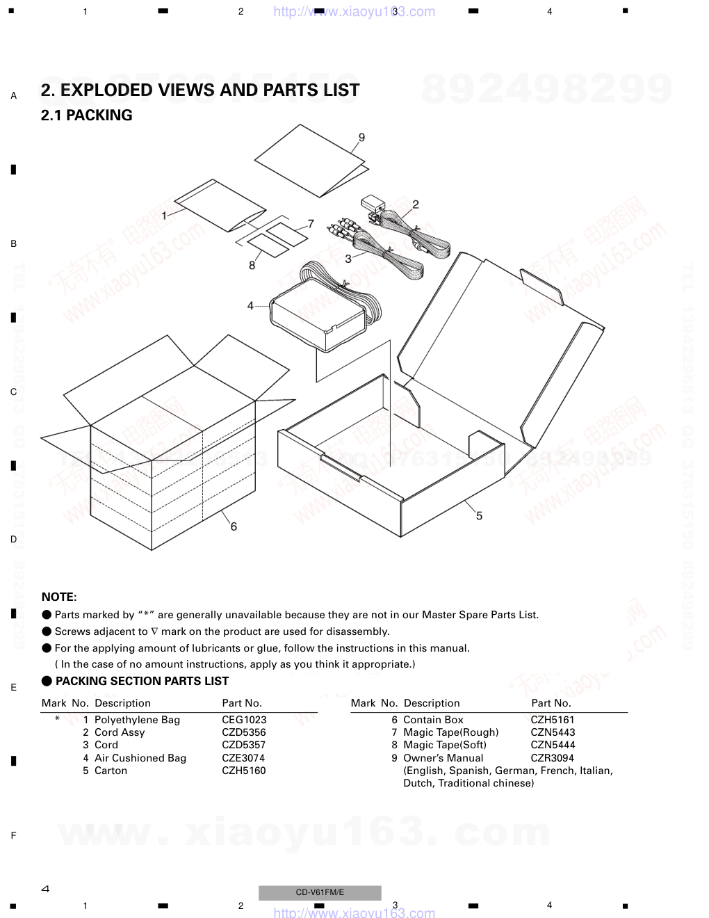
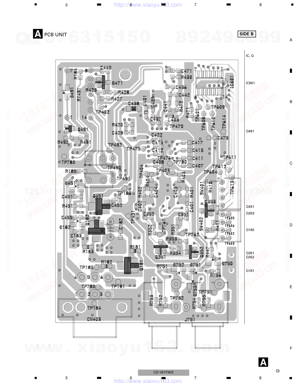
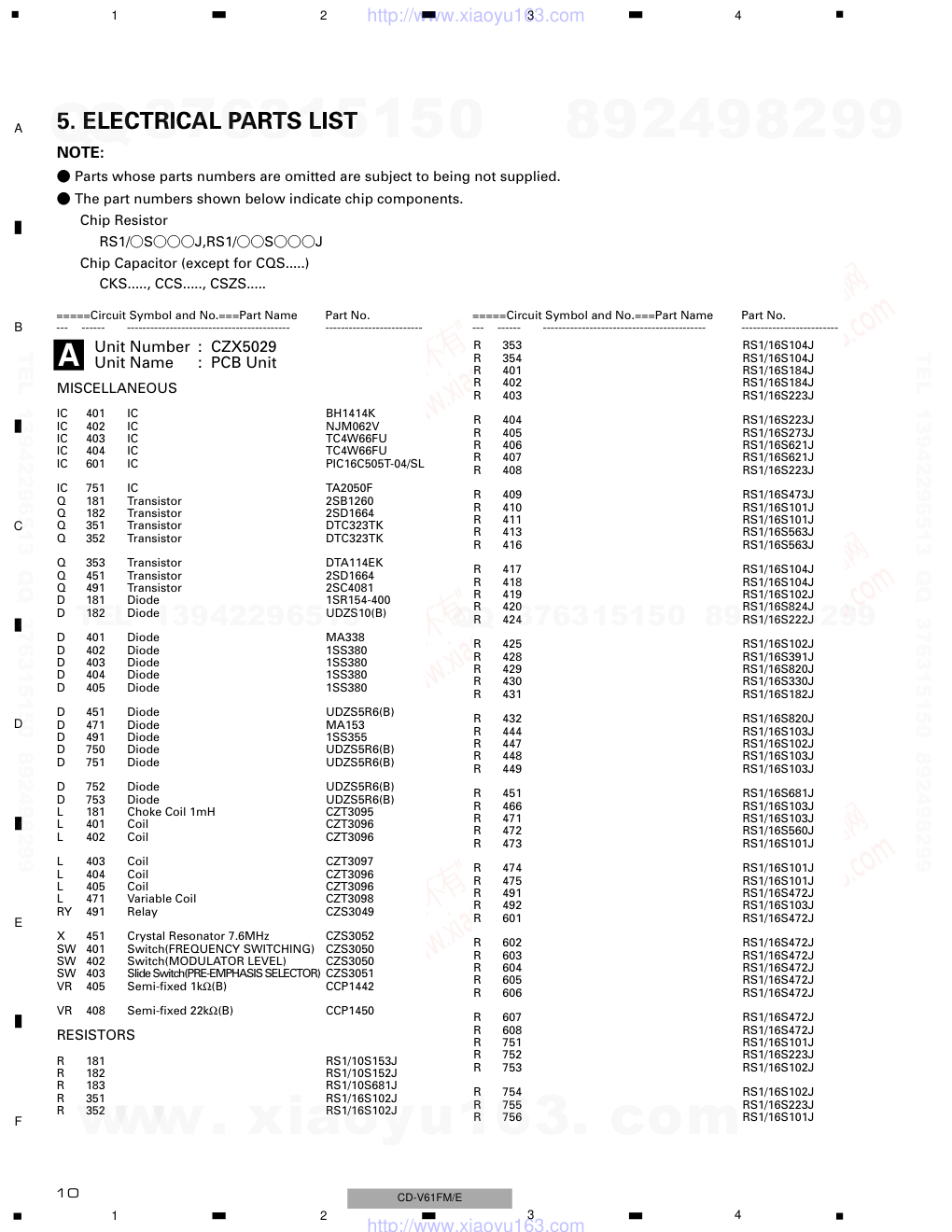
PIONEER CORPORATION 4-1, Meguro 1-Chome, Meguro-ku, Tokyo 153-8654, Japan PIONEER ELECTRONICS (USA) INC. P.O.Box 1760, Long Beach, CA 90801-1760 U.S.A. PIONEER EUROPE NV Haven 1087 Keetberglaan 1, 9120 Melsele, Belgium PIONEER ELECTRONICS ASIACENTRE PTE.LTD. 253 Alexandra Road, #04-01, Singapore 159936 C PIONEER CORPORATION 2002 K-ZZA. JULY 2002 Printed in Japan ORDER NO. CRT2873 FM MODULATOR CD-V61FM E Service Manual CD-V61FM/E CONTENTS 1. SPECIFICATIONS........................................................3 2. EXPLODED VIEWS AND PARTS LIST.......................4 3. SCHEMATIC DIAGRAM .............................................6 4. PCB CONNECTION DIAGRAM ..................................8 5. ELECTRICAL PARTS LIST ........................................10 6. ADJUSTMENT..........................................................12 7. GENERAL INFORMATION .......................................15 7.1 IC ........................................................................15 8. OPERATIONS............................................................15 For details, refer to "Important symbols for good services". www. xiaoyu163. com QQ 376315150 9 9 2 8 9 4 2 9 8 TEL 13942296513 9 9 2 8 9 4 2 9 8 0 5 1 5 1 3 6 7 3 Q Q TEL 13942296513 QQ 376315150 892498299 TEL 13942296513 QQ 376315150 892498299 http://www.xiaoyu163.com 2 1 2 3 4 1 2 3 4 F E D C B A CD-V61FM/E [ Important symbols for good services ] In this manual, the symbols shown-below indicate that adjustments, settings or cleaning should be made securely. When you find the procedures bearing any of the symbols, be sure to fulfill them: 2. Adjustments To keep the original performances of the product, optimum adjustments or specification confirmation is indispensable. In accordance with the procedures or instructions described in this manual, adjustments should be performed. 3. Cleaning For optical pickups, tape-deck heads, lenses and mirrors used in projection monitors, and other parts requiring cleaning, proper cleaning should be performed to restore their performances. 5. Lubricants, glues, and replacement parts Appropriately applying grease or glue can maintain the product performances. But improper lubrication or applying glue may lead to failures or troubles in the product. By following the instructions in this manual, be sure to apply the prescribed grease or glue to proper portions by the appropriate amount.For replacement parts or tools, the prescribed ones should be used. 4. Shipping mode and shipping screws To protect the product from damages or failures that may be caused during transit, the shipping mode should be set or the shipping screws should be installed before shipping out in accordance with this manual, if necessary. 1. Product safety You should conform to the regulations governing the product (safety, radio and noise, and other regulations), and should keep the safety during servicing by following the safety instructions described in this manual. SAFETY INFORMATION CAUTION This service manual is intended for qualified service technicians; it is not meant for the casual do-it-yourselfer. Qualified technicians have the necessary test equipment and tools, and have been trained to properly and safely repair complex products such as those covered by this manual. Improperly performed repairs can adversely affect the safety and reliability of the product and may void the warranty. If you are not qualified to perform the repair of this product properly and safely, you should not risk trying to do so and refer the repair to a qualified service technician. WARNING This product contains lead in solder and certain electrical parts contain chemicals which are known to the state of California to cause cancer, birth defects or other reproductive harm. Health & Safety Code Section 25249.6 - Proposition 65 www. xiaoyu163. com QQ 376315150 9 9 2 8 9 4 2 9 8 TEL 13942296513 9 9 2 8 9 4 2 9 8 0 5 1 5 1 3 6 7 3 Q Q TEL 13942296513 QQ 376315150 892498299 TEL 13942296513 QQ 376315150 892498299 http://www.xiaoyu163.com 3 5 6 7 8 F E D C B A 5 6 7 8 CD-V61FM/E Power source ....................... 14.4 V DC (10.8 – 15.1 V allowable) Max. current consumption ............................................... 200 mA Backup current ....................................................................... 0 mA Weight .................................................................................... 220 g Dimensions ...................................... 89 (W) × 25 (H) × 64 (D) mm FM modulator usable frequency .... 88.1/88.3/88.5/88.7/88.9/89.1 /89.3/89.5/89.7/89.9 MHz Note: Specifications and the design are subject to possible modification without notice due to improvements. 1. SPECIFICATIONS www. xiaoyu163. com QQ 376315150 9 9 2 8 9 4 2 9 8 TEL 13942296513 9 9 2 8 9 4 2 9 8 0 5 1 5 1 3 6 7 3 Q Q TEL 13942296513 QQ 376315150 892498299 TEL 13942296513 QQ 376315150 892498299 http://www.xiaoyu163.com 4 1 2 3 4 1 2 3 4 F E D C B A CD-V61FM/E 2. EXPLODED VIEWS AND PARTS LIST 2.1 PACKING * 1 Polyethylene Bag CEG1023 2 Cord Assy CZD5356 3 Cord CZD5357 4 Air Cushioned Bag CZE3074 5 Carton CZH5160 6 Contain Box CZH5161 7 Magic Tape(Rough) CZN5443 8 Magic Tape(Soft) CZN5444 9 Owner’s Manual CZR3094 (English, Spanish, German, French, Italian, Dutch, Traditional chinese) Mark No. Description Part No. Mark No. Description Part No. - PACKING SECTION PARTS LIST NOTE: - Parts marked by “*” are generally unavailable because they are not in our Master Spare Parts List. - Screws adjacent to ∇ mark on the product are used for disassembly. - For the applying amount of lubricants or glue, follow the instructions in this manual. ( In the case of no amount instructions, apply as you think it appropriate.) www. xiaoyu163. com QQ 376315150 9 9 2 8 9 4 2 9 8 TEL 13942296513 9 9 2 8 9 4 2 9 8 0 5 1 5 1 3 6 7 3 Q Q TEL 13942296513 QQ 376315150 892498299 TEL 13942296513 QQ 376315150 892498299 http://www.xiaoyu163.com 5 5 6 7 8 F E D C B A 5 6 7 8 CD-V61FM/E 2.2 EXTERIOR 1 Modulator CZX5028 2 Screw BSZ30P050FMC 3 Antenna Cord CZD5358 4 Antenna Cord CZD5359 5 Chassis CZN5448 6 Holder CZN5449 7 Terminal(EP1) CKF1064 8 Connector(CN403) CKM1077 9 Antenna Jack(CN491) CKX1010 10 Antenna Jack(CN492) CKX1010 11 Pin Jack(J751) CZK3065 12 Screw PPZ26P080S- 13 Top Case Assy CZX5039 14 Screw ISS30P060FMC 15 Screw PMZ30P080FNN Mark No. Description Part No. Mark No. Description Part No. - EXTERIOR SECTION PARTS LIST www. xiaoyu163. com QQ 376315150 9 9 2 8 9 4 2 9 8 TEL 13942296513 9 9 2 8 9 4 2 9 8 0 5 1 5 1 3 6 7 3 Q Q TEL 13942296513 QQ 376315150 892498299 TEL 13942296513 QQ 376315150 892498299 http://www.xiaoyu163.com 6 1mH PRE-EMPHASIS SELECTOR CZS3051 1 2 3 4 1 2 3 4 F E D C B A CD-V61FM/E 3. SCHEMATIC DIAGRAM 3.1 PCB UNIT Note: When ordering service parts, be sure to refer to “EXPLODED VIEWS AND PARTS LIST” or “ELECTRICAL PARTS LIST”. A www. xiaoyu163. com QQ 376315150 9 9 2 8 9 4 2 9 8 TEL 13942296513 9 9 2 8 9 4 2 9 8 0 5 1 5 1 3 6 7 3 Q Q TEL 13942296513 QQ 376315150 892498299 TEL 13942296513 QQ 376315150 892498299 http://www.xiaoyu163.com 7 MODULATOR LEVEL ROTARY SWITCH CZS3050 CZS3050 FREQUENCY SWITCHING ROTARY SWITCH PIC16C505T-04/SL 5 6 7 8 F E D C B A 5 6 7 8 CD-V61FM/E A A PCB UNIT www. xiaoyu163. com QQ 376315150 9 9 2 8 9 4 2 9 8 TEL 13942296513 9 9 2 8 9 4 2 9 8 0 5 1 5 1 3 6 7 3 Q Q TEL 13942296513 QQ 376315150 892498299 TEL 13942296513 QQ 376315150 892498299 http://www.xiaoyu163.com 8 A A PCB UNIT SIDE A FREQUENCY SWITCHING ROTARY SWITCH MODULATOR LEVEL ROTARY SWITCH PRE-EMPHASIS SELECTOR IC, Q IC402 IC401 IC403 IC404 IC751 ADJ L471 VR405 VR408 1 2 3 4 1 2 3 4 F E D C B A CD-V61FM/E NOTE FOR PCB DIA- GRAMS 1. The parts mounted on this PCB include all necessary parts for several destination. For further informa- tion for respective destinations, be sure to check with the schematic diagram. 2. Viewpoint of PCB dia- grams Capacitor Connector P.C.Board Chip Part SIDE A SIDE B 4. PCB CONNECTION DIAGRAM 4.1 PCB UNIT www. xiaoyu163. com QQ 376315150 9 9 2 8 9 4 2 9 8 TEL 13942296513 9 9 2 8 9 4 2 9 8 0 5 1 5 1 3 6 7 3 Q Q TEL 13942296513 QQ 376315150 892498299 TEL 13942296513 QQ 376315150 892498299 http://www.xiaoyu163.com 9 A A PCB UNIT SIDE B IC, Q IC601 Q491 Q451 Q353 Q182 Q351 Q352 Q181 5 6 7 8 F E D C B A 5 6 7 8 CD-V61FM/E www. xiaoyu163. com QQ 376315150 9 9 2 8 9 4 2 9 8 TEL 13942296513 9 9 2 8 9 4 2 9 8 0 5 1 5 1 3 6 7 3 Q Q TEL 13942296513 QQ 376315150 892498299 TEL 13942296513 QQ 376315150 892498299 http://www.xiaoyu163.com 10 1 2 3 4 1 2 3 4 F E D C B A CD-V61FM/E R 353 RS1/16S104J R 354 RS1/16S104J R 401 RS1/16S184J R 402 RS1/16S184J R 403 RS1/16S223J R 404 RS1/16S223J R 405 RS1/16S273J R 406 RS1/16S621J R 407 RS1/16S621J R 408 RS1/16S223J R 409 RS1/16S473J R 410 RS1/16S101J R 411 RS1/16S101J R 413 RS1/16S563J R 416 RS1/16S563J R 417 RS1/16S104J R 418 RS1/16S104J R 419 RS1/16S102J R 420 RS1/16S824J R 424 RS1/16S222J R 425 RS1/16S102J R 428 RS1/16S391J R 429 RS1/16S820J R 430 RS1/16S330J R 431 RS1/16S182J R 432 RS1/16S820J R 444 RS1/16S103J R 447 RS1/16S102J R 448 RS1/16S103J R 449 RS1/16S103J R 451 RS1/16S681J R 466 RS1/16S103J R 471 RS1/16S103J R 472 RS1/16S560J R 473 RS1/16S101J R 474 RS1/16S101J R 475 RS1/16S101J R 491 RS1/16S472J R 492 RS1/16S103J R 601 RS1/16S472J R 602 RS1/16S472J R 603 RS1/16S472J R 604 RS1/16S472J R 605 RS1/16S472J R 606 RS1/16S472J R 607 RS1/16S472J R 608 RS1/16S472J R 751 RS1/16S101J R 752 RS1/16S223J R 753 RS1/16S102J R 754 RS1/16S102J R 755 RS1/16S223J R 756 RS1/16S101J 5. ELECTRICAL PARTS LIST NOTE: - Parts whose parts numbers are omitted are subject to being not supplied. - The part numbers shown below indicate chip components. Chip Resistor RS1/_S___J,RS1/__S___J Chip Capacitor (except for CQS.....) CKS....., CCS....., CSZS..... Unit Number : CZX5029 Unit Name : PCB Unit MISCELLANEOUS IC 401 IC BH1414K IC 402 IC NJM062V IC 403 IC TC4W66FU IC 404 IC TC4W66FU IC 601 IC PIC16C505T-04/SL IC 751 IC TA2050F Q 181 Transistor 2SB1260 Q 182 Transistor 2SD1664 Q 351 Transistor DTC323TK Q 352 Transistor DTC323TK Q 353 Transistor DTA114EK Q 451 Transistor 2SD1664 Q 491 Transistor 2SC4081 D 181 Diode 1SR154-400 D 182 Diode UDZS10(B) D 401 Diode MA338 D 402 Diode 1SS380 D 403 Diode 1SS380 D 404 Diode 1SS380 D 405 Diode 1SS380 D 451 Diode UDZS5R6(B) D 471 Diode MA153 D 491 Diode 1SS355 D 750 Diode UDZS5R6(B) D 751 Diode UDZS5R6(B) D 752 Diode UDZS5R6(B) D 753 Diode UDZS5R6(B) L 181 Choke Coil 1mH CZT3095 L 401 Coil CZT3096 L 402 Coil CZT3096 L 403 Coil CZT3097 L 404 Coil CZT3096 L 405 Coil CZT3096 L 471 Variable Coil CZT3098 RY 491 Relay CZS3049 X 451 Crystal Resonator 7.6MHz CZS3052 SW 401 Switch(FREQUENCY SWITCHING) CZS3050 SW 402 Switch(MODULATOR LEVEL) CZS3050 SW 403 Slide Switch(PRE-EMPHASIS SELECTOR) CZS3051 VR 405 Semi-fixed 1kΩ(B) CCP1442 VR 408 Semi-fixed 22kΩ(B) CCP1450 RESISTORS R 181 RS1/10S153J R 182 RS1/10S152J R 183 RS1/10S681J R 351 RS1/16S102J R 352 RS1/16S102J =====Circuit Symbol and No.===Part Name Part No. --- ------ ------------------------------------------ ------------------------- =====Circuit Symbol and No.===Part Name Part No. --- ------ ------------------------------------------ ------------------------- A www. xiaoyu163. com QQ 376315150 9 9 2 8 9 4 2 9 8 TEL 13942296513 9 9 2 8 9 4 2 9 8 0 5 1 5 1 3 6 7 3 Q Q TEL 13942296513 QQ 376315150 892498299 TEL 13942296513 QQ 376315150 892498299 http://www.xiaoyu163.com 11 5 6 7 8 F E D C B A 5 6 7 8 CD-V61FM/E CAPACITORS C 181 1000µF/25V CZC5168 C 182 CKSRYB103K50 C 183 CKSRYB103K50 C 184 CEV101M16 C 185 CEV101M16 C 351 CKSRYB105K10 C 352 CKSRYB105K10 C 401 CKSRYB104K16 C 402 CKSRYB104K16 C 403 CCSRCH331J50 C 404 CCSRCH331J50 C 405 CKSRYB103K50 C 406 CKSRYB103K50 C 407 CKSRYB103K50 C 408 CKSRYB103K50 C 409 CKSRYB103K50 C 410 CKSRYB103K50 C 411 CKSRYB103K50 C 412 CKSRYB103K50 C 413 CKSRYB103K50 C 414 CKSRYB103K50 C 415 CKSRYB105K10 C 416 CKSRYB105K10 C 417 CKSRYB103K50 C 418 CEV101M16 C 419 CKSRYB103K50 C 420 CCSRCH220J50 C 421 CCSRCH220J50 C 422 CKSRYB105K10 C 423 CKSRYB474K10 C 424 CCSRCH331J50 C 425 CSZS100M10 C 426 CKSRYB103K50 C 427 CEV4R7M35 C 429 CKSRYB474K10 C 430 CCSRCH471J50 C 431 CCSRCH820J50 C 433 CCSRCH150J50 C 434 CCSRCH330J50 C 435 CCSRCH180J50 C 436 CCSRCH271J50 C 437 CKSRYB103K50 C 438 CKSQYB105K16 C 439 CKSRYB103K50 C 440 CKSRYB103K50 C 441 CCSRCH101J50 C 442 CCSRCH680J50 C 443 CCSRCH121J50 C 444 CCSRCH121J50 C 445 CCSRCH221J50 C 446 CCSRCH221J50 C 447 CKSQYB154K25 C 448 CKSQYB154K25 C 451 CKSRYB105K10 C 452 CKSRYB103K50 C 453 CEV101M16 C 455 CKSRYB103K50 C 456 CEV101M16 C 457 CKSRYB104K16 C 458 CKSRYB104K16 C 462 CKSRYB103K50 C 463 CKSRYB103K50 C 471 CKSRYB103K50 C 472 CKSRYB472K50 C 473 CKSRYB103K50 C 491 CEV101M16 C 761 CEV1R0M50 C 762 CEV1R0M50 C 763 CEV100M16 C 764 CEV220M16 C 765 CEV1R0M50 C 766 CEV1R0M50 =====Circuit Symbol and No.===Part Name Part No. --- ------ ------------------------------------------ ------------------------- =====Circuit Symbol and No.===Part Name Part No. --- ------ ------------------------------------------ ------------------------- www. xiaoyu163. com QQ 376315150 9 9 2 8 9 4 2 9 8 TEL 13942296513 9 9 2 8 9 4 2 9 8 0 5 1 5 1 3 6 7 3 Q Q TEL 13942296513 QQ 376315150 892498299 TEL 13942296513 QQ 376315150 892498299 http://www.xiaoyu163.com 12 1 2 3 4 1 2 3 4 F E D C B A CD-V61FM/E 6. ADJUSTMENT - ADJUSTMENT POINT, TEST POINT VR405 L471 VR408 IC401 TP402 TP492 TP183 TP451 TP752 TP751 www. xiaoyu163. com QQ 376315150 9 9 2 8 9 4 2 9 8 TEL 13942296513 9 9 2 8 9 4 2 9 8 0 5 1 5 1 3 6 7 3 Q Q TEL 13942296513 QQ 376315150 892498299 TEL 13942296513 QQ 376315150 892498299 http://www.xiaoyu163.com 13 5 6 7 8 F E D C B A 5 6 7 8 CD-V61FM/E Digital multi- meter No. Item Mode Input signals (input test pin, standard, or other measuring conditions) Output signals (measuring test pin, waveforms) Measuring devices Standard (or other notes) Parts to adjust Modulator adjust- ment and inspection 1 Preparation for adjustment and inspection 400Hz, 1Vrms, SIN audio input to J751, TP751, TP752 Modulator PWSW ON Frequency 89.1MHz(Rotary switch : 5) Modulator level +6(Rotary switch : 9) The following adjustments and inspections are performed in the above mode unless something is specified. Also, 1Vrms = 0dB. 2 Check of power supply voltage TP183 DC TP451 DC 9.0 ± 1.0V 5.0 ± 0.3V 3 Check of input signals TP751 SIN TP752 SIN Oscilloscope A : 2.8V ± 70mV 4 19kHz filter check Audio input L/R, 19kHz, SIN IC401 40PIN IC401 16PIN Oscilloscope A : 100mVp-p or less 5 PLL lock adjustment Audio input OFF TP402 DC Digital multi- meter 4.0 ± 0.2VDC Frequency 89.1MHz ± 10kHz L471 A Minimum 2.8V A www. xiaoyu163. com QQ 376315150 9 9 2 8 9 4 2 9 8 TEL 13942296513 9 9 2 8 9 4 2 9 8 0 5 1 5 1 3 6 7 3 Q Q TEL 13942296513 QQ 376315150 892498299 TEL 13942296513 QQ 376315150 892498299 http://www.xiaoyu163.com 14 1 2 3 4 1 2 3 4 F E D C B A CD-V61FM/E 6 Stereo pilot check Audio input OFF TP492 Stereo receiver or demodulator Spectrum analyzer Stereo receiver or demodulator Spectrum analyzer 7.5 ± 1.5kHz (A ; 14.0 ± 1.5dB) value for reference 135 ± 10kHz (A ; 135 ± 10kHz) value for reference 7 Adjustment of modulation level Audio input 1Vrms, 400Hz TP492 VR408 8 Adjustment of RF output level Audio input OFF TP492 Spectrum analyzer or high- frequency electronic voltmeter + counter 60 ± 3dBµV 75-ohm terminal Frequency 89.1MHz ± 10kHz VR405 40mVp-p Value for reference 19kHz 19kHz A A A No. Item Mode Input signals (input test pin, standard, or other measuring conditions) Output signals (measuring test pin, waveforms) Measuring devices Standard (or other notes) Parts to adjust Oscilloscope www. xiaoyu163. com QQ 376315150 9 9 2 8 9 4 2 9 8 TEL 13942296513 9 9 2 8 9 4 2 9 8 0 5 1 5 1 3 6 7 3 Q Q TEL 13942296513 QQ 376315150 892498299 TEL 13942296513 QQ 376315150 892498299 http://www.xiaoyu163.com 15 5 6 7 8 F E D C B A 5 6 7 8 CD-V61FM/E - Pin Function (PIC16C505T-04/SL) Pin No. Pin Name I/O Function and Operation 1 VDD Positive supply for logic and I/O pins 2 RB5/OSC1/CLKIN I/O Bi-directional I/O port/oscillator crystal input/external clock source input 3 RB4/OSC2/CLKOUT I/O Bi-directional I/O port/oscillator crystal output 4 RB3/mclr/VPP I Input port/master clear (reset) input/programming voltage input 5 RC5/T0CKI I/O Bi-directional I/O port 6-10 RC4-0 I/O Bi-directional I/O port 11 RB2 I/O Bi-directional I/O port 12 RB1 I/O Bi-directional I/O port/ serial programming clock 13 RB0 I/O Bi-directional I/O port/ serial programming data 14 VSS Ground reference for logic and I/O pins *PIC16C505T-04/SL 1 7 8 14 8. OPERATIONS 7. GENERAL INFORMATION 7.1 IC 1 This product 2 Left (White) 3 Right (Red) 4 Power switch (cable: 2 m) 5 Red(ACC) To electric terminal controlled by ignition switch (12 V DC) ON/OFF. Do not connect this lead to power source terminals to which power is continuously supplied. If the lead is connected to such terminals, the battery may be drained. 6 Fuse holder 7 Black (ground) To vehicle (metal) body. 8 Antenna output (1.5 m) 9 Antenna input (1.5 m) 0 RCA cable (supplied, 6 m) ! To audio outputs @ Car antenna plug # Car stereo with FM tuner $ Pioneer overhead monitor % Pioneer source DVD player (stand-alone mode) ^ Pioneer TV tuner & Pioneer DVD player (stand-alone mode) * Velcro tape ( Floor mat ) Frequency switching rotary switch • You can switch the FM band frequency received by your car radio. Set it to a frequency that is not used by an FM radio broadcast station in your area. If there is interference, use a standard tip screwdriver or other instrument to turn the switch clockwise or counterclockwise to select another frequency. ⁄ Modulator level rotary switch • You can adjust volume level. At the time of purchase, the switch is set to 4. If you think the volume level is too low to listen to FM broadcasts on your car radio, use a standard tip screwdriver or other instrument to turn the switch clockwise. If you think the volume level is too high or there is distortion, turn the switch counterclockwise. The higher the setting number, the higher the volume level. ¤ Pre-emphasis selector • Normally, set the pre-emphasis selector to “2”. (The initial setting is “2”.) • If you feel the treble is insufficient, switch the selector to “3” with the tip of a pen or other pointed instrument to boost the treble slightly. • If you feel the treble is too strong and the sound becomes distorted, either return the selector to “2” or switch it to “1”. IC's marked by * are MOS type. Be careful in handling them because they are very liable to be damaged by electrostatic induction. www. xiaoyu163. com QQ 376315150 9 9 2 8 9 4 2 9 8 TEL 13942296513 9 9 2 8 9 4 2 9 8 0 5 1 5 1 3 6 7 3 Q Q TEL 13942296513 QQ 376315150 892498299 TEL 13942296513 QQ 376315150 892498299 http://www.xiaoyu163.com 16 1 2 3 4 1 2 3 4 F E D C B A CD-V61FM/E Fig. 1 Fig. 2 Fig. 3 Fig. 4 Fig. 5 2 ! 0 9 8 @ # 3 $ % 1 4 5 6 7 2 ! 0 9 8 @ # 3 $ 1 ^ 4 5 6 7 & 2 ! 0 9 8 @ # 3 1 4 5 6 7 1 ( * ) ⁄ 1 ¤ www. xiaoyu163. com QQ 376315150 9 9 2 8 9 4 2 9 8 TEL 13942296513 9 9 2 8 9 4 2 9 8 0 5 1 5 1 3 6 7 3 Q Q TEL 13942296513 QQ 376315150 892498299 TEL 13942296513 QQ 376315150 892498299 http://www.xiaoyu163.com
版权声明
1. 本站所有素材,仅限学习交流,仅展示部分内容,如需查看完整内容,请下载原文件。
2. 会员在本站下载的所有素材,只拥有使用权,著作权归原作者所有。
3. 所有素材,未经合法授权,请勿用于商业用途,会员不得以任何形式发布、传播、复制、转售该素材,否则一律封号处理。
4. 如果素材损害你的权益请联系客服QQ:77594475 处理。