先锋PIONEER AVX-P7000CD音响电路原理图
 "先锋PIONEER AVX-P7000CD音响电路原理图-0")
 "先锋PIONEER AVX-P7000CD音响电路原理图-1")
 "先锋PIONEER AVX-P7000CD音响电路原理图-2")
 "先锋PIONEER AVX-P7000CD音响电路原理图-3")
 "先锋PIONEER AVX-P7000CD音响电路原理图-4")
 "先锋PIONEER AVX-P7000CD音响电路原理图-5")
 "先锋PIONEER AVX-P7000CD音响电路原理图-6")
 "先锋PIONEER AVX-P7000CD音响电路原理图-7")
 "先锋PIONEER AVX-P7000CD音响电路原理图-8")
 "先锋PIONEER AVX-P7000CD音响电路原理图-9")
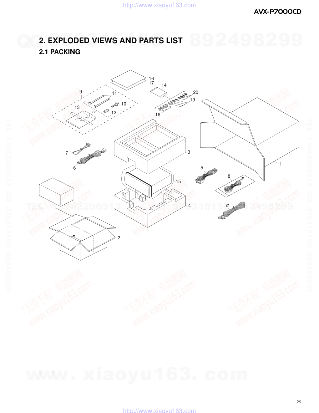
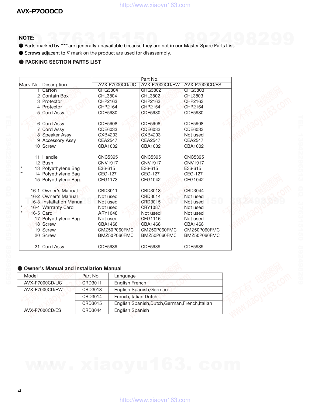
PIONEER ELECTRONIC CORPORATION 4-1, Meguro 1-Chome, Meguro-ku, Tokyo 153-8654, Japan PIONEER ELECTRONICS SERVICE INC. P.O.Box 1760, Long Beach, CA 90801-1760 U.S.A. PIONEER ELECTRONIC [EUROPE] N.V. Haven 1087 Keetberglaan 1, 9120 Melsele, Belgium PIONEER ELECTRONICS ASIACENTRE PTE.LTD. 253 Alexandra Road, #04-01, Singapore 159936 C PIONEER ELECTRONIC CORPORATION 1999 K-ZZU. APR. 1999 Printed in Japan ORDER NO. CRT2379 7 INCH WIDE AV SYSTEM DISPLAY/CD PLAYER AVX-P7000CD�UC Service Manual CONTENTS 1. SAFETY INFORMATION............................................2 2. EXPLODED VIEWS AND PARTS LIST ......................3 3. BLOCK DIAGRAM AND SCHEMATIC DIAGRAM ..12 4. PCB CONNECTION DIAGRAM................................31 5. ELECTRICAL PARTS LIST........................................41 6. ADJUSTMENT.........................................................46 7. GENERAL INFORMATION.......................................48 7.1DIAGNOSIS ........................................................48 7.1.1 TEST MODE .............................................48 7.1.2 DISASSEMBLY.........................................52 7.1.3 PCB LOCATIONS......................................59 7.2IC .........................................................................60 7.3MECHANISM DESCRIPTIONS...........................66 8. OPERATIONS AND SPECIFICATIONS....................70 NOTE: - See the separate manual CX-680(CRT2216) for the cassette mechanism description. - The CD mechanism assy employed in this model is one of H1 series. - For the details of the LCD module and the drive mech unit, refer to the separate manual CRT2276. AVX-P7000CD�EW AVX-P7000CD�ES www. xiaoyu163. com QQ 376315150 9 9 2 8 9 4 2 9 8 TEL 13942296513 9 9 2 8 9 4 2 9 8 0 5 1 5 1 3 6 7 3 Q Q TEL 13942296513 QQ 376315150 892498299 TEL 13942296513 QQ 376315150 892498299 http://www.xiaoyu163.com 2 AVX-P7000CD - CD Player Service Precautions 1. For pickup unit(CXX1290) handling, please refer to"Disassembly"(see page 55). During replacement, handling precautions shall be taken to prevent an electrostatic discharge(protection by a short pin). 2. During disassembly, be sure to turn the power off since an internal IC might be destroyed when a connector is plugged or unplugged. 3. Please checking the grating after changing the service pickup unit(see page 46). 1. Safety Precautions for those who Service this Unit. • When checking or adjusting the emitting power of the laser diode exercise caution in order to get safe, reliable results. Caution: 1. During repair or tests, minimum distance of 13cm from the focus lens must be kept. 2. During repair or tests, do not view laser beam for 10 seconds or longer. 2. A “CLASS 1 LASER PRODUCT” label is affixed to the rear of the player. 3. The triangular label is attached to the mechanism unit frame. 4. Specifications of Laser Diode Specifications of laser radiation fields to which human access is possible during service. Wavelength = 800 nanometers CLASS 1 LASER PRODUCT 1. SAFETY INFORMATION CAUTION This service manual is intended for qualified service technicians; it is not meant for the casual do-it-yourselfer. Qualified technicians have the necessary test equipment and tools, and have been trained to properly and safely repair complex products such as those covered by this manual. Improperly performed repairs can adversely affect the safety and reliability of the product and may void the warranty. If you are not qualified to perform the repair of this product properly and safely, you should mot risk trying to do so and refer the repair to a qualified service technician. WARNING This product contains lead in solder and certain electrical parts contain chemicals which are known to the state of California to cause cancer, birth defects or other reproductive harm. Health & Safety Code Section 25249.6 - Proposition 65 www. xiaoyu163. com QQ 376315150 9 9 2 8 9 4 2 9 8 TEL 13942296513 9 9 2 8 9 4 2 9 8 0 5 1 5 1 3 6 7 3 Q Q TEL 13942296513 QQ 376315150 892498299 TEL 13942296513 QQ 376315150 892498299 http://www.xiaoyu163.com 12 11 13 10 9 1 2 3 4 15 16 6 7 14 17 18 19 20 5 8 3 AVX-P7000CD 2. EXPLODED VIEWS AND PARTS LIST 2.1 PACKING 21 www. xiaoyu163. com QQ 376315150 9 9 2 8 9 4 2 9 8 TEL 13942296513 9 9 2 8 9 4 2 9 8 0 5 1 5 1 3 6 7 3 Q Q TEL 13942296513 QQ 376315150 892498299 TEL 13942296513 QQ 376315150 892498299 http://www.xiaoyu163.com 4 AVX-P7000CD NOTE: - Parts marked by “*”are generally unavailable because they are not in our Master Spare Parts List. - Screws adjacent to ∇ mark on the product are used for disassembly. - PACKING SECTION PARTS LIST Part No. Mark No. Description AVX-P7000CD/UC AVX-P7000CD/EW AVX-P7000CD/ES 1 Carton CHG3804 CHG3802 CHG3803 2 Contain Box CHL3804 CHL3802 CHL3803 3 Protector CHP2163 CHP2163 CHP2163 4 Protector CHP2164 CHP2164 CHP2164 5 Cord Assy CDE5930 CDE5930 CDE5930 6 Cord Assy CDE5908 CDE5908 CDE5908 7 Cord Assy CDE6033 CDE6033 CDE6033 8 Speaker Assy CXB4203 CXB4203 Not used 9 Accessory Assy CEA2547 CEA2547 CEA2547 10 Screw CBA1002 CBA1002 CBA1002 11 Handle CNC5395 CNC5395 CNC5395 12 Bush CNV1917 CNV1917 CNV1917 * 13 Polyethylene Bag E36-615 E36-615 E36-615 * 14 Polyethylene Bag CEG-127 CEG-127 CEG-127 15 Polyethylene Bag CEG1173 CEG1042 CEG1042 16-1 Owner's Manual CRD3011 CRD3013 CRD3044 16-2 Owner's Manual Not used CRD3014 Not used 16-3 Installation Manual Not used CRD3015 Not used * 16-4 Warranty Card Not used CRY1087 Not used * 16-5 Card ARY1048 Not used Not used 17 Polyethylene Bag Not used CEG1116 Not used 18 Screw CBA1468 CBA1468 CBA1468 19 Screw CMZ50P060FMC CMZ50P060FMC CMZ50P060FMC 20 Screw BMZ50P060FMC BMZ50P060FMC BMZ50P060FMC 21 Cord Assy CDE5939 CDE5939 CDE5939 - Owner's Manual and Installation Manual Model Part No. Language AVX-P7000CD/UC CRD3011 English,French AVX-P7000CD/EW CRD3013 English,Spanish,German CRD3014 French,Italian,Dutch CRD3015 English,Spanish,Dutch,German,French,Italian AVX-P7000CD/ES CRD3044 English,Spanish www. xiaoyu163. com QQ 376315150 9 9 2 8 9 4 2 9 8 TEL 13942296513 9 9 2 8 9 4 2 9 8 0 5 1 5 1 3 6 7 3 Q Q TEL 13942296513 QQ 376315150 892498299 TEL 13942296513 QQ 376315150 892498299 http://www.xiaoyu163.com 5 AVX-P7000CD 2.2 EXTERIOR(1/2) www. xiaoyu163. com QQ 376315150 9 9 2 8 9 4 2 9 8 TEL 13942296513 9 9 2 8 9 4 2 9 8 0 5 1 5 1 3 6 7 3 Q Q TEL 13942296513 QQ 376315150 892498299 TEL 13942296513 QQ 376315150 892498299 http://www.xiaoyu163.com 6 AVX-P7000CD EXTERIOR(2/2) www. xiaoyu163. com QQ 376315150 9 9 2 8 9 4 2 9 8 TEL 13942296513 9 9 2 8 9 4 2 9 8 0 5 1 5 1 3 6 7 3 Q Q TEL 13942296513 QQ 376315150 892498299 TEL 13942296513 QQ 376315150 892498299 http://www.xiaoyu163.com 7 AVX-P7000CD 1 Screw BMZ26P050FZK 2 IC(IC24) PNA4603H00LB 3 Screw BSZ26P040FMC 4 Screw BSZ30P040FMC 5 Transistor(Q1801,Q1809) 2SD2396 6 Screw(M2x2) CBA1487 7 Connector CDE5925 8 Cord Assy CDE5930 9 Fuse(4A) CEK1001 10 Cap CNS1472 11 Screw UFZ26P030FMC 12 Resistor RS1/2PMF102J 13 Case CNB2458 14 Holder CNC6798 15 Bracket CNC8260 16 Bracket CNC8261 17 Holder CNC8359 18 Holder CNC8387 19 Insulator CNM6199 20 Insulator CNM6201 21 PCB CNP5539 22 Panel See Contrast table(2) 23 Cord Assy See Contrast table(2) 24 Cord Assy See Contrast table(2) 25 Cord Assy CDE6138 26 System Micro Computer Unit See Contrast table(2) 27 Screw ASZ26P100FMC 28 Clamper CEF1009 29 Plug(CN1801) CKS-461 30 Connector(CN1604) CKS3125 31 Connector(CN1601) CKS4064 32 Connector(CN1602) CKS4064 33 Connector(CN1603) CKS4066 34 Holder CNC8259 35 Heat Sink CNC8262 36 CD Micro Computer Unit CWM6444 37 Connector(CN2601) CKS1968 38 Connector(CN2002) CKS3132 39 Connector(CN2001) CKS3133 40 Connector(CN2901) CKS3133 41 Connector(CN2902) CKS3971 42 Connector(CN2602) CKS4054 43 Connector(CN2603) CKS4063 44 Connector(CN2604) CKS4063 45 Connector(CN2605) CKS4065 46 IC(IC1) SBX8035-H 47 Spacer CNM6200 48 Rack CNV5737 49 Rack CNV5738 50 Chassis Unit CXB3769 51 Screw BPZ20P100FMC 52 Screw BPZ20P120FZK 53 Screw BPZ26P050FMC 54 Button(ANGEL,WIDE) See Contrast table(2) 55 Screw See Contrast table(2) 56 Screw CBA1481 57 Screw CBA1482 58 Screw CBA1484 59 Connector CDE5924 60 Case CNC8405 61 ••••• 62 Insulator CNM6314 63 Insulator CNM6315 64 Insulator CNM6339 65 Insulator CNM6340 66 PCB CNP5449 67 PCB CNP5451 68 Cover See Contrast table(2) 69 Holder CNV5744 70 Holder CNV5842 71 Relay Unit CWM6425 72 Connector(CN52) CKS3124 73 Connector(CN53) CKS3124 74 Connector(CN57) CKS3125 75 Connector(CN51) CKS3802 76 Connector(CN55) CKS4132 77 LCD Keyboard Unit See Contrast table(2) 78 Connector(CN21) CKS4057 79 Spacer CNM6271 80 Encoder Unit CWM6587 81 Screw CBA1483 82 Connector(CN56) CKS3125 83 Bracket CNC8406 84 Gear CNV5841 85 LCD Module CWX2389 86 Grille Unit See Contrast table(2) 87 Drive Mechanism Unit See Contrast table(2) 88 Screw BPZ20P060FMC 89 Button CAC6025 90 Button CAC6026 (1) EXTERIOR SECTION PARTS LIST Mark No. Description Part No. Mark No. Description Part No. www. xiaoyu163. com QQ 376315150 9 9 2 8 9 4 2 9 8 TEL 13942296513 9 9 2 8 9 4 2 9 8 0 5 1 5 1 3 6 7 3 Q Q TEL 13942296513 QQ 376315150 892498299 TEL 13942296513 QQ 376315150 892498299 http://www.xiaoyu163.com 8 AVX-P7000CD Mark No. Description Part No. * 91 Cover CNM6470 92 Panel Keyboard Unit See Contrast table(2) 93 Connector(CN1) CKS4054 94 Spacer CNM6272 95 Grille Unit See Contrast table(2) 96 Detach Grille Assy See Contrast table(2) 97 Screw BPZ20P060FZK 98 Button(Detach) See Contrast table(2) 99 Button(+) See Contrast table(2) 100 Button(-) See Contrast table(2) 101 Button(CD EJECT) See Contrast table(2) 102 Button(OPEN/CLOSE) See Contrast table(2) 103 Button(RESET) See Contrast table(2) 104 Spring CBH2239 105 Spring CBH2302 106 Cover See Contrast table(2) 107 Grille See Contrast table(2) 108 CD Mechanism Module(H1) CXK5141 109 Cord Assy See Contrast table(2) 110 Cord Assy See Contrast table(2) www. xiaoyu163. com QQ 376315150 9 9 2 8 9 4 2 9 8 TEL 13942296513 9 9 2 8 9 4 2 9 8 0 5 1 5 1 3 6 7 3 Q Q TEL 13942296513 QQ 376315150 892498299 TEL 13942296513 QQ 376315150 892498299 http://www.xiaoyu163.com 9 AVX-P7000CD (2) CONTRAST TABLE AVX-P7000CD/UC , AVX-P7000CD/EW and AVX-P7000CD/ES are constructed the same except for the following: Part No. Mark No. Description AVX-P7000CD/UC AVX-P7000CD/EW AVX-P7000CD/ES 22 Panel CNS5427 CNS5427 CNS5550 23 Cord Assy CDE5934 CDE5934 Not used 24 Cord Assy CDE6030 CDE6030 Not Used 26 System Micro Computer Unit CWM6430 CWM6431 CWM6430 54 Button CAC6107 CAC6107 CAC6024 55 Screw CBA1477 CBA1477 CBA1475 68 Cover CNS5499 CNS5499 CNS5420 77 LCD Keyboard Unit CWM6426 CWM6427 CWM6426 86 Grille Unit CXB4533 CXB4533 CXB4534 87 Drive Mechanism Unit CXB4204 CXB4204 CXB4205 92 Panel Keyboard Unit CWM6439 CWM6438 CWM6439 95 Grille Unit CXB4554 CXB4554 CXB4551 96 Detach Grille Assy CXB4227 CXB4226 CXB4228 98 Button CAC6031 CAC6031 CAC6151 99 Button CAC6108 CAC6108 CAC6027 100 Button CAC6109 CAC6109 CAC6028 101 Button CAC6110 CAC6110 CAC6029 102 Button CAC6111 CAC6111 CAC6030 103 Button CAC6112 CAC6112 CAC6032 106 Cover CNS5503 CNS5503 CNS5424 107 Grille CNS5504 CNS5502 CNS5505 109 Cord Assy Not used Not used CDE5937 110 Cord Assy Not used Not used CDE6070 www. xiaoyu163. com QQ 376315150 9 9 2 8 9 4 2 9 8 TEL 13942296513 9 9 2 8 9 4 2 9 8 0 5 1 5 1 3 6 7 3 Q Q TEL 13942296513 QQ 376315150 892498299 TEL 13942296513 QQ 376315150 892498299 http://www.xiaoyu163.com 10 AVX-P7000CD 2.3 CD MECHANISM MODULE www. xiaoyu163. com QQ 376315150 9 9 2 8 9 4 2 9 8 TEL 13942296513 9 9 2 8 9 4 2 9 8 0 5 1 5 1 3 6 7 3 Q Q TEL 13942296513 QQ 376315150 892498299 TEL 13942296513 QQ 376315150 892498299 http://www.xiaoyu163.com 11 AVX-P7000CD Mark No. Description Part No. Mark No. Description Part No. 1 Control Unit CWX2350 2 Connector(CN701) CKS1968 3 Connector(CN802) CKS3477 4 Connector(CN801) CKS3481 5 Connector(CN101) CKS3486 6 Screw BMZ20P025FMC 7 Screw(M2×2.5) CBA1037 8 Screw(M2×5) CBA1296 9 Screw(M2×1.8) CBA1340 10 Screw(M2×4) CBA1362 11 Screw(M2×9) CBA1440 12 Spring CBH2029 13 Spring CBH2030 14 Spring CBH2031 15 Spring CBH2032 16 Spring CBH2033 17 Spring CBH2207 18 Spring CBH2040 19 Spring CBH2041 20 Spring CBH2042 21 Spring CBH2052 22 Shaft CLA3232 23 Frame CNC8264 24 Frame CNC7286 25 Lever CNC7288 26 Lever CNC7289 27 Cover CNC7294 28 Cover CNC7304 29 Sheet CNM5401 30 Sheet CNM5402 31 Sheet CNM5814 32 PCB CNP4854 33 Belt CNT1082 34 Damper CNV5855 35 Gear CNV5080 36 Gear CNV5081 37 Gear CNV5082 38 Holder CNV5098 39 Guide CNV5352 40 Mechanism FPC Unit CWX2191 41 Connector CKS3767 * 42 PCB CNP4852 * 43 Arm CNC7287 44 ••••• 45 ••••• 46 ••••• 47 Bracket CNC7300 * 48 CRG Motor Unit CXB1671 49 Screw JFZ14P020FNI 50 Washer CBF1037 51 Spring CBH2039 52 Rack CNV5471 53 Bracket Unit CXB1674 54 Screw Unit CXB1676 55 Chassis Unit CXB3042 56 Washer CBF1038 57 Spring CBH2035 58 Spring CBH2036 59 Lever CNV5078 60 Lever Unit CXB3207 61 Arm Unit CXB1680 62 Washer CBF1038 63 Gear CNV5083 64 Gear CNV5084 65 Bracket Unit CXB1682 66 Bracket CNC7292 67 ••••• 68 LOAD Motor Unit(M2) CXB1684 69 Screw JFZ14P020FNI 70 Screw(M2×2) CBA1451 71 Washer CBF1037 72 Washer CBF1060 73 Screw CBH2170 74 Roller CLA3222 75 Roller CNV3412 76 Arm CNV5075 77 Roller Gear Unit CXB1686 78 Bracket Unit CXB2627 79 ••••• 80 ••••• 81 Washer YE20FUC 82 Guide Arm Assy CXB1688 83 Photo-transistor(P1-3) CPT-230S-X 84 Clamp Arm Assy CXB3137 85 ••••• * 86 Sheet CNM5398 87 ••••• 88 Motor(M3) CXM1129 89 Washer YE25FUC 90 Pickup Unit(Service) CXX1290 91 Screw IMS20P035FMC 92 Spring CBH2206 93 Bracket CNC7977 94 ••••• 95 Sheet CNM6055 96 CRG Motor Assy(M1) CXB1670 97 Spring CBL1412 98 Screw IMS20P025FMC - CD MECHANISM MODULE SECTION PARTS LIST www. xiaoyu163. com QQ 376315150 9 9 2 8 9 4 2 9 8 TEL 13942296513 9 9 2 8 9 4 2 9 8 0 5 1 5 1 3 6 7 3 Q Q TEL 13942296513 QQ 376315150 892498299 TEL 13942296513 QQ 376315150 892498299 http://www.xiaoyu163.com 12 AVX-P7000CD 3. BLOCK DIAGRAM AND SCHEMATIC DIAGRAM 3.1 BLOCK DIAGRAM B A E G J H I MECHANISM FPC UNIT PHOTO FPC UNIT www. xiaoyu163. com QQ 376315150 9 9 2 8 9 4 2 9 8 TEL 13942296513 9 9 2 8 9 4 2 9 8 0 5 1 5 1 3 6 7 3 Q Q TEL 13942296513 QQ 376315150 892498299 TEL 13942296513 QQ 376315150 892498299 http://www.xiaoyu163.com 13 AVX-P7000CD D C F www. xiaoyu163. com QQ 376315150 9 9 2 8 9 4 2 9 8 TEL 13942296513 9 9 2 8 9 4 2 9 8 0 5 1 5 1 3 6 7 3 Q Q TEL 13942296513 QQ 376315150 892498299 TEL 13942296513 QQ 376315150 892498299 http://www.xiaoyu163.com 14 AVX-P7000CD A 1 2 3 4 B C D 1 2 3 4 B CD MICRO COMPUTER UNIT SYSTEM MICRO COMPUTER CD REGULATOR VDD REGULATOR VIDEO REGU CN2603 CN2604 CN2605 A 3.2 SYSTEM MICRO COMPUTER UNIT Note: When ordering service parts, be sure to refer to “EXPLODED VIEWS AND PARTS LIST” or “ELECTRICAL PARTS LIST”. www. xiaoyu163. com QQ 376315150 9 9 2 8 9 4 2 9 8 TEL 13942296513 9 9 2 8 9 4 2 9 8 0 5 1 5 1 3 6 7 3 Q Q TEL 13942296513 QQ 376315150 892498299 TEL 13942296513 QQ 376315150 892498299 http://www.xiaoyu163.com 15 AVX-P7000CD 5 6 7 8 A B C D 5 6 7 8 A DEO REGULATOR SYSTEM MICRO COMPUTER UNIT 1K(1/2W) 1mH MOTOR DRIVER 16K 2R2K C1818 C1817 I.SENS GND V.SEL A www. xiaoyu163. com QQ 376315150 9 9 2 8 9 4 2 9 8 TEL 13942296513 9 9 2 8 9 4 2 9 8 0 5 1 5 1 3 6 7 3 Q Q TEL 13942296513 QQ 376315150 892498299 TEL 13942296513 QQ 376315150 892498299 http://www.xiaoyu163.com 16 AVX-P7000CD A 1 2 3 4 B C D 1 2 3 4 A A A CN1603 CN1602 CN1601 CD MICRO COMPUTER G CN701 AUDIO SELECT IP-BUS:2.2dBs IP-BUS:2.2dBs S-CD:2.52dBs S-CD:0.22dBs CONTROL UNIT B 3.3 CD MICRO COMPUTER UNIT www. xiaoyu163. com QQ 376315150 9 9 2 8 9 4 2 9 8 TEL 13942296513 9 9 2 8 9 4 2 9 8 0 5 1 5 1 3 6 7 3 Q Q TEL 13942296513 QQ 376315150 892498299 TEL 13942296513 QQ 376315150 892498299 http://www.xiaoyu163.com 17 AVX-P7000CD 5 6 7 8 A B C D 5 6 7 8 J C SYNCHRONIZING SEPARATION B CD MICRO COMUTER UNIT UC,EW model CN51 RELAY UNIT B www. xiaoyu163. com QQ 376315150 9 9 2 8 9 4 2 9 8 TEL 13942296513 9 9 2 8 9 4 2 9 8 0 5 1 5 1 3 6 7 3 Q Q TEL 13942296513 QQ 376315150 892498299 TEL 13942296513 QQ 376315150 892498299 http://www.xiaoyu163.com 18 AVX-P7000CD A 1 2 3 4 B C D 1 2 3 4 8R2K F ENCODER UNIT C RELAY UNIT B CN2902 ANGLE SENSOR BACK SENSOR SW M51 M52 FX2484 FX2484 10k(B) C 3.4 RELAY UNIT AND ENCODER UNIT F www. xiaoyu163. com QQ 376315150 9 9 2 8 9 4 2 9 8 TEL 13942296513 9 9 2 8 9 4 2 9 8 0 5 1 5 1 3 6 7 3 Q Q TEL 13942296513 QQ 376315150 892498299 TEL 13942296513 QQ 376315150 892498299 http://www.xiaoyu163.com 19 AVX-P7000CD 5 6 7 8 A B C D 5 6 7 8 T D CN21 LCD MODULE LCD KEYBOARD UNIT C www. xiaoyu163. com QQ 376315150 9 9 2 8 9 4 2 9 8 TEL 13942296513 9 9 2 8 9 4 2 9 8 0 5 1 5 1 3 6 7 3 Q Q TEL 13942296513 QQ 376315150 892498299 TEL 13942296513 QQ 376315150 892498299 http://www.xiaoyu163.com 20 AVX-P7000CD A 1 2 3 4 B C D 1 2 3 4 3.5 LCD KEYBOARD UNIT D D C CN55 LCD KEYBOARD UNIT FULL NORMAL JUST ZOOM CINEMA EW model UC,ES model UC,ES model EW model UC,ES model:CSG1112 EW model:CSG1113 S21-S23 www. xiaoyu163. com QQ 376315150 9 9 2 8 9 4 2 9 8 TEL 13942296513 9 9 2 8 9 4 2 9 8 0 5 1 5 1 3 6 7 3 Q Q TEL 13942296513 QQ 376315150 892498299 TEL 13942296513 QQ 376315150 892498299 http://www.xiaoyu163.com 21 AVX-P7000CD 1 2 3 4 A B C D 1 2 3 4 E SML210LT E B CN2602 PANEL KEYBOARD UNIT EW model UC,ES model UC,ES model EW model EW model J SW UNIT S52 CSN1052 SENSOR SW J 3.6 PANEL KEYBOARD UNIT www. xiaoyu163. com QQ 376315150 9 9 2 8 9 4 2 9 8 TEL 13942296513 9 9 2 8 9 4 2 9 8 0 5 1 5 1 3 6 7 3 Q Q TEL 13942296513 QQ 376315150 892498299 TEL 13942296513 QQ 376315150 892498299 http://www.xiaoyu163.com 22 AVX-P7000CD A 1 2 3 4 B C D 1 2 3 4 3.7 CD MECHANISM MODULE(GUIDE PAGE) G-a G I H PICKUP UNIT (SERVICE) H MECHANISM FPC UNIT I PHOTO FPC UNIT G-a G-b G-a G-b G-b G-a Large size SCH diagram Guide page Detailed page www. xiaoyu163. com QQ 376315150 9 9 2 8 9 4 2 9 8 TEL 13942296513 9 9 2 8 9 4 2 9 8 0 5 1 5 1 3 6 7 3 Q Q TEL 13942296513 QQ 376315150 892498299 TEL 13942296513 QQ 376315150 892498299 http://www.xiaoyu163.com 23 AVX-P7000CD 5 6 7 8 A B C D 5 6 7 8 NOTE 1) GND . . . CD LSI (AGND Analog, DGND Digital) PGND . . . Actuator, Motor Driver AAGND . . . Audio These GND's are not connected to each other on PCB, though they use same symbols in this schematic. PGND is connected to a chassis by a screw. NOTE 2) Pull-up resistors of EJTSNS, DSCSNS should be 47kΩ. G-b G G CONTROL UNIT CN2601 B www. xiaoyu163. com QQ 376315150 9 9 2 8 9 4 2 9 8 TEL 13942296513 9 9 2 8 9 4 2 9 8 0 5 1 5 1 3 6 7 3 Q Q TEL 13942296513 QQ 376315150 892498299 TEL 13942296513 QQ 376315150 892498299 http://www.xiaoyu163.com 24 AVX-P7000CD A 1 2 3 4 B C D 1 2 3 4 G-a G-b G-a G CONTROL UNIT PICKUP UNIT (SERVICE) 1 2 3 4 5 6 www. xiaoyu163. com QQ 376315150 9 9 2 8 9 4 2 9 8 TEL 13942296513 9 9 2 8 9 4 2 9 8 0 5 1 5 1 3 6 7 3 Q Q TEL 13942296513 QQ 376315150 892498299 TEL 13942296513 QQ 376315150 892498299 http://www.xiaoyu163.com 25 AVX-P7000CD 5 6 7 8 A B C D 5 6 7 8 NOTE 1) GN PG AA T on P NOTE 2) Pu G-a G-b G-a I H H MECHANISM FPC UNIT I PHOTO FPC UNIT 7 www. xiaoyu163. com QQ 376315150 9 9 2 8 9 4 2 9 8 TEL 13942296513 9 9 2 8 9 4 2 9 8 0 5 1 5 1 3 6 7 3 Q Q TEL 13942296513 QQ 376315150 892498299 TEL 13942296513 QQ 376315150 892498299 http://www.xiaoyu163.com 26 AVX-P7000CD A 1 2 3 4 B C D 1 2 3 4 G-a G-b G-b 1 2 3 4 5 6 www. xiaoyu163. com QQ 376315150 9 9 2 8 9 4 2 9 8 TEL 13942296513 9 9 2 8 9 4 2 9 8 0 5 1 5 1 3 6 7 3 Q Q TEL 13942296513 QQ 376315150 892498299 TEL 13942296513 QQ 376315150 892498299 http://www.xiaoyu163.com 27 AVX-P7000CD 5 6 7 8 A B C D 5 6 7 8 TE 1) GND . . . CD LSI (AGND Analog, DGND Digital) PGND . . . Actuator, Motor Driver AAGND . . . Audio These GND's are not connected to each other on PCB, though they use same symbols in this schematic. PGND is connected to a chassis by a screw. TE 2) Pull-up resistors of EJTSNS, DSCSNS should be 47kΩ. G-a G-b G-b CN2601 B 7 www. xiaoyu163. com QQ 376315150 9 9 2 8 9 4 2 9 8 TEL 13942296513 9 9 2 8 9 4 2 9 8 0 5 1 5 1 3 6 7 3 Q Q TEL 13942296513 QQ 376315150 892498299 TEL 13942296513 QQ 376315150 892498299 http://www.xiaoyu163.com 28 AVX-P7000CD 1 RFO 0.5V/div. 0.5µs/div. Normal mode: play 1 CH1: RFO 1V/div. 2 CH2: MIRR 5V/div. Test mode: Tracking open 0.5ms/div. 1 CH1: RFO 1V/div. 2 CH2: MIRR 5V/div. Normal mode: The defect part passes 800µm 0.5ms/div. 3 CH1: FIN 0.5V/div. 4 CH2: FO+ 2V/div. Test mode: No disc, Focus close 0.2s/div. 3 CH1: FIN 0.5V/div. 5 CH2: FOK 2V/div. Normal mode: Focus close 0.2s/div. 6 CH1: FEY 0.5V/div. 7 CH2: XSI 2V/div. Normal mode: Focus close 1ms/div. REFO → 8 CH1: TEY 0.5V/div. 9 CH2: TIN 0.5V/div. Test mode: 32 tracks jump (FWD) 0.5ms/div. 8 CH1: TEY 0.5V/div. 9 CH2: TIN 0.5V/div. Test mode: Single jump (FWD) 0.5ms/div. 8 CH1: TEY 0.5V/div. 9 CH2: TIN 0.5V/div. Test mode: 100 tracks jump (FWD) 5ms/div. 6 CH1: FEY 0.1V/div. 3 CH2: FIN 0.2V/div. Normal mode: Play 20ms/div. 3 CH1: FIN 0.5V/div. 0 CH2: SIN 1V/div. Normal mode: Focus close (12cm) 0.5s/div. 3 CH1: FIN 0.5V/div. 0 CH2: SIN 1V/div. Normal mode: Focus close (8cm) 0.5s/div. GND → GND → REFO → REFO → REFO → REFO → GND → REFO → REFO → GND → REFO → REFO → REFO → REFO → REFO → REFO → REFO → REFO → REFO → REFO → REFO → REFO → - Waveforms Note:1. The encircled numbers denote measuring pointes in the circuit diagram. 2. Reference voltage REFO:2.5V www. xiaoyu163. com QQ 376315150 9 9 2 8 9 4 2 9 8 TEL 13942296513 9 9 2 8 9 4 2 9 8 0 5 1 5 1 3 6 7 3 Q Q TEL 13942296513 QQ 376315150 892498299 TEL 13942296513 QQ 376315150 892498299 http://www.xiaoyu163.com 29 AVX-P7000CD 8 CH1: TEY 0.2V/div. 9 CH2: TIN 0.2V/div. Normal mode: play 8 CH1: TEY 0.5V/div. ! CH2: SD 0.5V/div. 5ms/div. 0 SIN 0.5V/div. 0.1s/div. Normal mode: Play (12cm) 0 SIN 1V/div. 10ms/div. Long Search (12cm) @ EFM 1V/div. 5µs/div. Play 8 CH1: TEY 1V/div. # CH2: TEC 1V/div. Test mode: Focus close Tracking open 2ms/div. 8 CH1: TEY 0.5V/div. 6 CH2: FEY 0.5V/div. Normal mode: AGC after focus close 0.2s/div. $ PLCK 2V/div. 0.5µs/div. Play 20ms/div. % SCKO 2V/div. 1µs/div. Play ^ Dout 2V/div. 10µs/div. Play & LRCK 2V/div. 20µs/div. * VD 5V/div. 50ms/div. Normal mode: No disc GND → REFO → REFO → GND → REFO → REFO → REFO → REFO → REFO → REFO → REFO → REFO → REFO → GND → REFO → GND → REFO → GND → REFO → GND → REFO → www. xiaoyu163. com QQ 376315150 9 9 2 8 9 4 2 9 8 TEL 13942296513 9 9 2 8 9 4 2 9 8 0 5 1 5 1 3 6 7 3 Q Q TEL 13942296513 QQ 376315150 892498299 TEL 13942296513 QQ 376315150 892498299 http://www.xiaoyu163.com 30 AVX-P7000CD ( CH1: R OUT 1V/div. ) CH2: L OUT 1V/div. Normal mode: Play (1kHz 0dB) 6 CH1: FEY 0.2V/div. 3 CH2: FIN 0.5V/div. Normal mode: During AGC 1ms/div. 8 CH1: TEY 0.2V/div. 9 CH2: TIN 0.5V/div. Normal mode: During AGC 1 CH1: RFO 1V/div. ⁄ CH2: HOLD 5V/div. Normal mode: The defect part passes 800µm 0.2ms/div. 1ms/div. 0.5ms/div. 3 CH1: FIN 1V/div. ⁄ CH2: HOLD 5V/div. Normal mode: The defect part passes 800µm 0.5ms/div. GND → GND → REFO → REFO → REFO → REFO → REFO → REFO → www. xiaoyu163. com QQ 376315150 9 9 2 8 9 4 2 9 8 TEL 13942296513 9 9 2 8 9 4 2 9 8 0 5 1 5 1 3 6 7 3 Q Q TEL 13942296513 QQ 376315150 892498299 TEL 13942296513 QQ 376315150 892498299 http://www.xiaoyu163.com 31 AVX-P7000CD 1 2 3 4 A B C D 1 2 3 4A CN2603 B SYSTEM MICRO COMPUTER UNIT 4. PCB CONNECTION DIAGRAM 4.1 SYSTEM MICRO COMPUTER UNIT NOTE FOR PCB DIAGRAMS 1. The parts mounted on this PCB include all necessary parts for several destination. For further information for respective destinations, be sure to check with the schematic diagram. 2. Viewpoint of PCB diagrams Capacitor Connector P.C.Board Chip Part SIDE A SIDE B A SIDE A SIDE B CN2604 B CN2605 B CORD ASSY SYSTEM MICRO COMPUTER UNIT A www. xiaoyu163. com QQ 376315150 9 9 2 8 9 4 2 9 8 TEL 13942296513 9 9 2 8 9 4 2 9 8 0 5 1 5 1 3 6 7 3 Q Q TEL 13942296513 QQ 376315150 892498299 TEL 13942296513 QQ 376315150 892498299 http://www.xiaoyu163.com 32 AVX-P7000CD A 1 2 3 4 B C D 1 2 3 4 B CD MICRO COMPUTER UNIT B SIDE A SIDE B CD MICRO COMPUTER UNIT B CN701 G CN1603 A CN51 C CN1602 A CN1601 A IP-BUS IP-BUS J 4.2 CD MICRO COMPUTER UNIT www. xiaoyu163. com QQ 376315150 9 9 2 8 9 4 2 9 8 TEL 13942296513 9 9 2 8 9 4 2 9 8 0 5 1 5 1 3 6 7 3 Q Q TEL 13942296513 QQ 376315150 892498299 TEL 13942296513 QQ 376315150 892498299 http://www.xiaoyu163.com RELAY UNIT C 33 AVX-P7000CD 1 2 3 4 A B C D 1 2 3 4 4.3 RELAY UNIT SIDE A C SIDE B 4.4 ENCODER UNIT CN57 C CN2902 B CN56 F M51 M52 LCD MODULE RELAY UNIT C ENCODER UNIT F F CN21 D www. xiaoyu163. com QQ 376315150 9 9 2 8 9 4 2 9 8 TEL 13942296513 9 9 2 8 9 4 2 9 8 0 5 1 5 1 3 6 7 3 Q Q TEL 13942296513 QQ 376315150 892498299 TEL 13942296513 QQ 376315150 892498299 http://www.xiaoyu163.com 34 AVX-P7000CD A 1 2 3 4 B C D 1 2 3 4 D WIDE ANGLE+ ANGLE- CN55 C LCD KEYBOARD UNIT D SIDE A SIDE B 4.5 LCD KEYBOARD UNIT LCD KEYBOARD UNIT D www. xiaoyu163. com QQ 376315150 9 9 2 8 9 4 2 9 8 TEL 13942296513 9 9 2 8 9 4 2 9 8 0 5 1 5 1 3 6 7 3 Q Q TEL 13942296513 QQ 376315150 892498299 TEL 13942296513 QQ 376315150 892498299 http://www.xiaoyu163.com 35 AVX-P7000CD 1 2 3 4 A B C D 1 2 3 4E CD EJECT BRIGHT- BRIGHT- BRIGHT+ DSEN RESET OPEN/CLOSE J PANEL KEYBOARD UNIT E SIDE A SIDE B 4.6 PANEL KEYBOARD UNIT PANEL KEYBOARD UNIT E www. xiaoyu163. com QQ 376315150 9 9 2 8 9 4 2 9 8 TEL 13942296513 9 9 2 8 9 4 2 9 8 0 5 1 5 1 3 6 7 3 Q Q TEL 13942296513 QQ 376315150 892498299 TEL 13942296513 QQ 376315150 892498299 http://www.xiaoyu163.com 36 AVX-P7000CD A 1 2 3 4 B C D 1 2 3 4 G CONTROL UNIT G SIDE A 4.7 CD MECHANISM MODULE www. xiaoyu163. com QQ 376315150 9 9 2 8 9 4 2 9 8 TEL 13942296513 9 9 2 8 9 4 2 9 8 0 5 1 5 1 3 6 7 3 Q Q TEL 13942296513 QQ 376315150 892498299 TEL 13942296513 QQ 376315150 892498299 http://www.xiaoyu163.com 37 AVX-P7000CD 1 2 3 4 A B C D 1 2 3 4 E F REFO M3 SPINDLE MOTOR PICKUP UNIT G CONTROL UNIT PICKUP UNIT (SERVICE) G SIDE B H CN2601 B www. xiaoyu163. com QQ 376315150 9 9 2 8 9 4 2 9 8 TEL 13942296513 9 9 2 8 9 4 2 9 8 0 5 1 5 1 3 6 7 3 Q Q TEL 13942296513 QQ 376315150 892498299 TEL 13942296513 QQ 376315150 892498299 http://www.xiaoyu163.com 38 AVX-P7000CD A 1 2 3 4 B C D 1 2 3 4 1 10 1 2 3 R5 R2 R3 R4 R1 D3 D1 D2 S1 CLAMP S2 HOME M M1 CARRIAGE M M2 LOADING H MECHANISM FPC UNIT H I CN801 G www. xiaoyu163. com QQ 376315150 9 9 2 8 9 4 2 9 8 TEL 13942296513 9 9 2 8 9 4 2 9 8 0 5 1 5 1 3 6 7 3 Q Q TEL 13942296513 QQ 376315150 892498299 TEL 13942296513 QQ 376315150 892498299 http://www.xiaoyu163.com 39 AVX-P7000CD 1 2 3 4 A B C D 1 2 3 4 1 2 3 P1 P3 P2 I PHOTO FPC UNIT I H www. xiaoyu163. com QQ 376315150 9 9 2 8 9 4 2 9 8 TEL 13942296513 9 9 2 8 9 4 2 9 8 0 5 1 5 1 3 6 7 3 Q Q TEL 13942296513 QQ 376315150 892498299 TEL 13942296513 QQ 376315150 892498299 http://www.xiaoyu163.com 40 AVX-P7000CD A 1 2 3 4 B C D 1 2 3 4 J J SW UNIT S52 4.8 SW UNIT CN1 E CN260 B www. xiaoyu163. com QQ 376315150 9 9 2 8 9 4 2 9 8 TEL 13942296513 9 9 2 8 9 4 2 9 8 0 5 1 5 1 3 6 7 3 Q Q TEL 13942296513 QQ 376315150 892498299 TEL 13942296513 QQ 376315150 892498299 http://www.xiaoyu163.com 41 AVX-P7000CD 5. ELECTRICAL PARTS LIST NOTE: - Parts whose parts numbers are omitted are subject to being not supplied. - The part numbers shown below indicate chip components. Chip Resistor RS1/_S___J,RS1/__S___J Chip Capacitor (except for CQS.....) CKS....., CCS....., CSZS..... Unit Number :CWM6430(UC,ES model) :CWM6431(EW model) Unit Name :System Micro Computer Unit MISCELLANEOUS IC 1601 IC PE5038A IC 1801 IC BA6247FP IC 1802 IC BA00ASFP Q 1602 Transistor DTB122JK Q 1603 Transistor IMX2 Q 1801 Transistor 2SD2396 Q 1802 Transistor UMD12N Q 1803 Transistor IMD3A Q 1805 Transistor 2SD1760F5 Q 1806 Transistor 2SA1036K Q 1807 Transistor 2SC4081 Q 1808 Transistor UMD12N Q 1809 Transistor 2SD2396 Q 1810 Transistor 2SA1797 Q 1811 Transistor 2SC4081 Q 1812 Transistor DTC124EU Q 1814 Transistor UMX2N Q 1815 Transistor DTA114EU Q 1816 Transistor DTC124EU D 1601 Diode MA8027(H) D 1602 Diode MA8027(H) D 1801 Diode MA8091(L) D 1802 Diode SC016-2 D 1803 Diode UDZS5R6(B) D 1805 Diode UDZS10(B) D 1806 Diode MA8068(M) D 1809 Diode MA8075(H) D 1810 Diode SC016-2 L 1601 Inductor CTF1399 L 1603 Inductor CTF1399 L 1604 Inductor CTF1399 L 1605 Inductor CTF1399 L 1801 Inductor CTF1487 FU 1801 Micro-Fuse 2A CEK1190 FU 1802 Micro-Fuse 400mA CEK1184 X 1601 Radiator 6.290MHz CSS1451 RESISTORS R 1610 RS1/16S473J R 1616 RS1/16S102J R 1618 RS1/16S102J R 1620 RS1/16S473J R 1624 RA2CQ473J R 1625 RA2CQ223J R 1626 RA2CQ473J R 1629 RS1/16S103J R 1630 (UC,ES model) RS1/16S473J R 1631 RS1/16S473J Unit Number : CWM6425 Unit Name : Relay Unit MISCELLANEOUS IC 51 IC TC74VHC123AFT Q 51 Transistor DTC124EU D 51 Diode MA110 D 52 Diode MA110 L 51 Inductor CTF1379 L 52 Inductor CTF1379 L 53 Inductor CTF1379 L 54 Inductor CTF1379 L 55 Inductor CTF1379 L 56 Inductor CTF1379 L 57 Inductor CTF1379 L 58 Inductor CTF1379 L 59 Inductor CTF1306 L 60 Inductor CTF1306 L 61 Inductor CTF1306 L 62 Inductor CTF1379 L 63 Inductor CTF1488 L 64 Inductor CTF1488 L 65 Inductor CTF1488 L 66 Inductor CTF1488 L 67 Inductor CTF1379 L 68 Inductor CTF1379 S 51 Spring Switch(Back sensor SW) CSN1033 RESISTORS R 51 RS1/16S332J R 52 RS1/16S102J R 53 RS1/16S473J R 54 RA3C102J R 56 RS1/16S103J R 57 RS1/16S102J R 58 RS1/10S102J R 59 RS1/16S822J R 60 RS1/10S102J R 61 RS1/16S822J CAPACITORS C 51 CCSRCH220J50 C 52 CCSRCH220J50 C 53 CCSRCH220J50 C 54 CKSQYB105K10 C 63 CKSRYB102K50 C 64 CKSRYB471K50 C 65 CCSRCH471J50 C 66 CKSYB475K10 =====Circuit Symbol and No.===Part Name Part No. --- ------ ------------------------------------------ ------------------------- =====Circuit Symbol and No.===Part Name Part No. --- ------ ------------------------------------------ ------------------------- A C www. xiaoyu163. com QQ 376315150 9 9 2 8 9 4 2 9 8 TEL 13942296513 9 9 2 8 9 4 2 9 8 0 5 1 5 1 3 6 7 3 Q Q TEL 13942296513 QQ 376315150 892498299 TEL 13942296513 QQ 376315150 892498299 http://www.xiaoyu163.com 42 AVX-P7000CD R 1801 RS1/4S221J R 1802 RS1/10S911J R 1803 RS1/16S822J R 1805 RS1/16S473J R 1806 RS1/10S272J R 1807 RS1/8S301J R 1809 RS1/16S472J R 1810 RS1/16S473J R 1811 RS1/4S331J R 1812 RS1/16S682J R 1813 RS1/16S473J R 1815 RS1/16S471J R 1816 RA4C102J R 1824 RS1/16S223J R 1825 RS1/16S473J R 1826 RS1/16S103J R 1827 RS1/16S473J R 1828 RS1/16S473J R 1829 RS1/16S473J R 1831 RS1/16S473J R 1832 RS1/16S103J R 1833 RS1/16S474J R 1834 RS1/16S163J R 1835 RS1/16S222J CAPACITORS C 1610 CKSRYB473K16 C 1611 CKSRYB473K16 C 1612 CKSRYB102K50 C 1616 CKSRYB104K16 C 1617 CKSRYB104K16 C 1801 100µF/16V CCH1228 C 1802 CKSRYB473K16 C 1803 CEHAT102M16 C 1804 CKSRYB103K50 C 1806 CKSRYB103K50 C 1807 CEV220M6R3 C 1808 CKSRYB103K50 C 1809 100µF/16V CCH1228 C 1810 CKSRYB473K16 C 1811 CEHAT102M16 C 1812 CKSRYB223K25 C 1813 CKSRYB223K25 C 1814 CEV101M10 C 1815 CKSQYB105K16 C 1816 CKSQYB105K16 C 1817 CKSRYB104K16 C 1818 CKSRYB104K16 C 1820 CKSRYB104K16 C 1821 CEHAT102M16 C 1822 CEH100M16 Unit Number : CWM6444 Unit Name : CD Micro Computer Unit MISCELLANEOUS IC 2001 IC TA2050F IC 2002 IC BA3129F IC 2601 IC PE5046B IC 2602 IC CA0008AM IC 2604 IC S-80734ANDYI IC 2801 IC NJM78L08UA IC 2901 IC TC7W34FU IC 2904 IC BA7071F Q 2001 Transistor FMG12 Q 2003 Transistor DTC144EU Q 2004 Transistor DTA114EU Q 2601 Transistor 2SC4081 Q 2602 Transistor DTC114TU Q 2603 Transistor 2SC4081 Q 2604 Transistor UMD12N Q 2606 Transistor UMG1 Q 2607 Transistor 2SC4081 Q 2608 Transistor 2SC4081 Q 2609 Transistor DTA114EU Q 2611 Transistor DTB123EK Q 2612 Transistor DTC115EUA D 2601 Diode MA8082(M) D 2602 Diode MA110 D 2603 Diode MA110 D 2604 Diode MA110 D 2605 Diode MA8075(H) D 2606 Diode MA110 D 2901 Diode MA8062(M) D 2902 Diode MA8062(M) D 2903 Diode MA8062(M) D 2904 Diode MA8062(M) FU 2901 Micro-Fuse 2A CEK1190 FU 2902 Micro-Fuse 2A CEK1190 FU 2903 Micro-Fuse 1A CEK1191 EF 2901 CCG1067 EF 2902 CCG1067 L 2601 Inductor LCTB2R2K2125 L 2602 Inductor CTF1399 L 2901 CTF1421 L 2902 Inductor LCTB2R2K2125 L 2905 Inductor LCTB2R2K2125 X 2601 Radiator 4.19MHz CSS1436 RESISTORS R 2001 RS1/16S181J R 2002 RS1/16S181J R 2003 RS1/16S223J R 2004 RS1/16S223J R 2005 RS1/16S102J R 2006 RS1/16S102J R 2007 RS1/16S821J R 2008 RS1/16S821J R 2009 RS1/16S223J R 2010 RS1/16S223J R 2011 RS1/16S104J R 2012 RS1/16S103J R 2013 RS1/16S103J R 2017 RS1/16S104J R 2018 RS1/16S104J R 2019 RS1/16S473J R 2025 RS1/16S333J R 2026 RS1/16S333J R 2027 RS1/16S683J R 2028 RS1/16S683J R 2029 RS1/16S433J R 2030 RS1/16S433J R 2601 RS1/16S472J R 2602 RS1/16S473J R 2604 RS1/16S101J R 2605 RS1/16S101J R 2606 RS1/16S102J R 2607 RS1/16S102J R 2608 RS1/16S473J R 2609 RS1/16S473J R 2610 RS1/16S472J R 2611 RS1/16S223J R 2612 RS1/16S473J R 2613 RS1/16S472J R 2614 RS1/16S392J =====Circuit Symbol and No.===Part Name Part No. --- ------ ------------------------------------------ ------------------------- =====Circuit Symbol and No.===Part Name Part No. --- ------ ------------------------------------------ ------------------------- B www. xiaoyu163. com QQ 376315150 9 9 2 8 9 4 2 9 8 TEL 13942296513 9 9 2 8 9 4 2 9 8 0 5 1 5 1 3 6 7 3 Q Q TEL 13942296513 QQ 376315150 892498299 TEL 13942296513 QQ 376315150 892498299 http://www.xiaoyu163.com 43 AVX-P7000CD R 2615 RS1/16S102J R 2616 RS1/16S473J R 2617 RS1/16S102J R 2618 RS1/16S473J R 2619 RS1/16S223J R 2620 RS1/16S223J R 2621 RS1/16S103J R 2622 RS1/16S223J R 2625 RS1/16S102J R 2626 RA3C221J R 2627 RS1/16S681J R 2628 RA3C221J R 2629 RA3C102J R 2630 RA3C221J R 2631 RA3C221J R 2632 RS1/16S472J R 2633 RS1/16S222J R 2634 RA2CQ473J R 2635 RA2CQ222J R 2636 RS1/16S473J R 2637 RS1/16S221J R 2638 RS1/16S102J R 2639 RA2CQ221J R 2640 RA2CQ221J R 2641 RS1/16S473J R 2642 RS1/16S222J R 2645 RS1/16S473J R 2646 RS1/16S473J R 2647 RA2CQ473J R 2648 RA2CQ473J R 2649 RS1/16S224J R 2650 RS1/16SS1003D R 2652 RS1/16S221J R 2653 RS1/16S473J R 2654 RA2CQ473J R 2902 RA2CQ471J R 2903 RS1/16S561J R 2905 RA2CQ471J CAPACITORS C 2001 CKSQYB105K10 C 2002 CKSQYB105K10 C 2003 CKSQYB105K10 C 2004 CKSQYB105K10 C 2005 CKSYB106K6R3 C 2006 CKSYB106K6R3 C 2007 CKSRYB222K50 C 2008 CKSRYB222K50 C 2009 CSZSR100M16 C 2010 CSZSR100M16 C 2011 CKSRYB104K16 C 2012 CKSRYB104K16 C 2013 CKSQYB105K10 C 2014 CKSQYB105K10 C 2015 CEV470M6R3 C 2019 CKSQYB105K10 C 2020 CKSQYB105K10 C 2021 CKSRYB221K50 C 2022 CKSRYB221K50 C 2023 CCSRCH330J50 C 2024 CCSRCH330J50 C 2601 CKSRYB102K50 C 2602 CKSRYB102K50 C 2603 CKSRYB104K16 C 2604 CKSRYB103K50 C 2605 CKSRYB103K50 C 2606 CKSRYB103K50 C 2607 CCSRCH220J50 C 2608 CKSRYB102K50 C 2609 CCSRCH220J50 C 2610 CCSRCH220J50 C 2611 CCSRCH220J50 C 2612 CCSRCH220J50 C 2615 CKSQYB105K10 C 2801 CKSRYB473K16 C 2802 CEV100M16 C 2803 CEV100M16 C 2901 CKSRYB103K50 C 2902 CKSRYB103K50 C 2909 CKSRYB561K50 C 2910 CKSRYB104K16 C 2912 CKSRYB103K50 C 2913 CKSRYB103K50 Unit Number : CWM6439(UC,ES model) CWM6438(EW model) Unit Name : Panel Keyboard Unit MISCELLANEOUS IC 1 IC SBX8035-H Q 1 Transistor(EW model) DTD114EK Q 2 Transistor(EW model) DTD114EK Q 3 Transistor(EW model) FMG1A D 1 LED SML210LT D 2 LED CL155DPGD D 3 LED CL170PGCD D 5 LED(EW model) CL170DCD S 1 Push Switch CSG1122 S 2 Push Switch CSG1122 S 3 Push Switch CSG1122 S 4 Push Switch CSG1122 S 5 Spring Switch CSN1046 S 6 Push Switch CSG1111 RESISTORS R 1 RS1/4S681J R 2 RS1/4S681J R 3 RS1/16S100J R 4 RS1/16S472J R 5 RS1/4S681J R 6 RS1/4S681J R 7 RS1/4S681J R 8 RS1/4S681J R 9 RS1/16S202J R 10 RS1/16S182J R 11 RS1/16S302J R 12 RS1/16S622J R 13 (UC,ES model) RS1/16S0R0J R 14 (UC,ES model) RS1/16S0R0J R 15 RS1/16S472J R 16 RS1/4S681J R 18 (EW model) RS1/10S0R0J CAPACITORS C 1 CKSQYB105K10 =====Circuit Symbol and No.===Part Name Part No. --- ------ ------------------------------------------ ------------------------- =====Circuit Symbol and No.===Part Name Part No. --- ------ ------------------------------------------ ------------------------- E www. xiaoyu163. com QQ 376315150 9 9 2 8 9 4 2 9 8 TEL 13942296513 9 9 2 8 9 4 2 9 8 0 5 1 5 1 3 6 7 3 Q Q TEL 13942296513 QQ 376315150 892498299 TEL 13942296513 QQ 376315150 892498299 http://www.xiaoyu163.com 44 AVX-P7000CD Unit Number : CWM6426(UC,ES model) CWM6427(EW model) Unit Name : LCD Keyboard Unit MISCELLANEOUS IC 21 IC BU2092FV IC 24 IC PNA4603H00LB Q 21 Transistor(EW model) UMG1 Q 22 Transistor DTC124EU D 25 LED SML020PDT D 26 LED SML020PDT D 27 LED SML020PDT D 28 LED SML020PDT D 29 LED SML020PDT D 30 LED SML020PDT L 21 Inductor LCTB2R2K2125 S 21 Push Switch(UC,ES model) CSG1112 S 21 Push Switch(EW model) CSG1113 S 22 Push Switch(UC,ES model) CSG1112 S 22 Push Switch(EW model) CSG1113 S 23 Push Switch(UC,ES model) CSG1112 S 23 Push Switch(EW model) CSG1113 RESISTORS R 21 RS1/16SS102J R 22 RS1/4S471J R 23 RS1/16S202J R 24 RS1/16S182J R 25 RS1/16S302J R 27 RS1/16S101J R 28 RS1/16S104J R 29 RS1/16S102J R 31 RS1/16S473J R 32 RS1/10S181J R 33 RS1/10S181J R 34 RS1/10S181J R 35 RS1/10S181J R 36 RS1/10S181J R 37 (UC,ES model) RS1/16S0R0J R 38 RS1/4S681J R 39 RS1/16S472J R 40 RS1/16SS102J R 41 (UC,ES model) RS1/16S0R0J R 47 (EW model) RS1/16S0R0J CAPACITORS C 21 CKSQYB105K10 C 23 CKSYB475K10 C 24 CKSQYB103K50 C 28 CKSRYB474K10 Unit Number : CWM6587 Unit Name : Encoder Unit MISCELLANEOUS VR 51 Volume 10kΩ(B) CCW1025 Unit Number : Unit Name : SW Unit MISCELLANEOUS S 52 Switch(SENSOR) CSN1052 Unit Number : CWX2350 Unit Name : Control Unit MISCELLANEOUS IC 101 IC UPC2572GS IC 201 IC UPD63702AGF IC 301 IC BA6797FM IC 501 IC PD4501B IC 601 IC TA2063F IC 702 IC BA05SFP IC 801 IC LB1930M Q 101 Transistor 2SD1664 Q 102 Transistor UMD2N Q 601 Transistor 2SD1781K Q 602 Transistor 2SD1781K Q 603 Transistor 2SB709A D 601 Diode MA151WA D 701 Diode 1SR154-400 X 201 Ceramic Oscillator 16.93MHz CSS1363 RESISTORS R 101 RS1/8S100J R 102 RS1/8S120J R 104 RS1/16S822J R 105 RS1/16S682J R 106 RS1/16S183J R 107 RS1/16S822J R 108 RS1/16S333J R 109 RS1/16S683J R 110 RS1/16S134J R 111 RS1/16S273J R 112 RS1/16S222J R 113 RS1/16S103J R 114 RS1/16S103J R 115 RS1/16S102J R 116 RS1/16S163J R 117 RS1/16S163J R 120 RS1/16S101J R 121 RS1/16S101J R 125 RS1/16S102J R 201 RS1/16S104J R 202 RS1/16S473J R 206 RS1/16S101J R 207 RS1/16S0R0J R 208 RS1/16S0R0J R 301 RS1/16S303J R 302 RS1/16S203J R 303 RS1/16S303J R 304 RS1/16S203J R 305 RS1/16S103J R 306 RS1/16S203J R 307 RS1/16S103J R 308 RS1/16S103J R 310 RS1/16S102J R 311 RS1/16S102J R 502 RS1/16S0R0J R 601 RS1/16S102J R 602 RS1/16S102J R 603 RS1/16S223J R 604 RS1/16S223J R 605 RS1/16S162J R 606 RS1/16S162J R 607 RS1/16S103J R 705 RS1/16S102J R 706 RS1/16S681J R 707 RS1/16S681J =====Circuit Symbol and No.===Part Name Part No. --- ------ ------------------------------------------ ------------------------- =====Circuit Symbol and No.===Part Name Part No. --- ------ ------------------------------------------ ------------------------- F D J G www. xiaoyu163. com QQ 376315150 9 9 2 8 9 4 2 9 8 TEL 13942296513 9 9 2 8 9 4 2 9 8 0 5 1 5 1 3 6 7 3 Q Q TEL 13942296513 QQ 376315150 892498299 TEL 13942296513 QQ 376315150 892498299 http://www.xiaoyu163.com 45 AVX-P7000CD R 708 RS1/16S681J R 709 RS1/16S681J R 710 RS1/16S102J R 714 RS1/16S102J R 716 RS1/16S0R0J R 717 RS1/16S0R0J R 718 RS1/16S102J CAPACITORS C 101 CEVL101M6R3 C 102 CKSQYB104K16 C 103 CEVL470M6R3 C 104 CKSQYB334K16 C 105 CCSRCH330J50 C 106 CKSRYB103K25 C 107 CEVL4R7M35 C 108 CKSRYB273K25 C 109 CCSRCH101J50 C 110 CKSQYB104K16 C 111 CKSRYB332K50 C 112 CKSRYB473K16 C 113 CKSRYB103K25 C 114 CKSRYB391K50 C 115 CCSRCH121J50 C 116 CKSRYB682K25 C 117 CKSRYB333K16 C 118 CKSQYB334K16 C 119 CKSQYB334K16 C 120 CKSQYB334K16 C 121 CKSQYB334K16 C 122 CKSQYB104K16 C 123 CKSRYB472K50 C 124 CKSQYB104K16 C 125 CCSRCH6R0D50 C 126 CKSRYB153K25 C 127 CCSRCH102J25 C 201 CKSQYB334K16 C 202 CKSQYB104K16 C 203 CKSQYB104K16 C 204 CKSRYB471K50 C 303 CEVL470M16 C 305 CKSRYB103K25 C 306 CKSRYB103K25 C 309 CKSYB475K10 C 601 CEV101M6R3 C 602 CKSQYB104K16 C 603 CEV220M6R3 C 604 CEV4R7M35 C 605 CEV4R7M35 C 606 CKLSRB152K50 C 607 CKLSRB152K50 C 701 CEV100M25 C 702 CKSQYB334K16 C 703 22µF/6.3V CCH1300 C 704 CEVL101M6R3 Unit Number : CWX2191 Unit Name : Mechanism FPC Unit D 1 LED CL200IRX D 2 LED CL200IRX D 3 LED CL200IRX S 1 Spring Switch(CLAMP) CSN1033 S 2 Spring Switch(HOME) CSN1033 R 1 RS1/8S0R0J R 2 RS1/8S0R0J R 3 RS1/8S751J R 4 RS1/8S751J R 5 RS1/8S751J Unit Number : Unit Name : Photo FPC Unit P 1 Photo-transistor CPT-230S-X P 2 Photo-transistor CPT-230S-X P 3 Photo-transistor CPT-230S-X Miscellaneous Parts List M 1 CRG Motor Assy(CARRIAGE) CXB1670 M 2 LOAD Motor Unit(LOADING) CXB1684 M 3 Motor(SPINDLE) CXM1129 Pickup Unit(Service) CXX1290 M 51 Motor(ANGLE) FX2484 M 52 Motor(POSITION) FX2484 =====Circuit Symbol and No.===Part Name Part No. --- ------ ------------------------------------------ ------------------------- =====Circuit Symbol and No.===Part Name Part No. --- ------ ------------------------------------------ ------------------------- H I www. xiaoyu163. com QQ 376315150 9 9 2 8 9 4 2 9 8 TEL 13942296513 9 9 2 8 9 4 2 9 8 0 5 1 5 1 3 6 7 3 Q Q TEL 13942296513 QQ 376315150 892498299 TEL 13942296513 QQ 376315150 892498299 http://www.xiaoyu163.com 46 AVX-P7000CD • Note : Unlike previous CD mechanism modules the grating angle of the PU unit cannot be adjusted after the PU unit is changed. The PU unit in the CD mechanism module is adjusted on the production line to match the CD mechanism module and is thus the best adjusted PU unit for the CD mechanism module. Changing the PU unit is thus best considered as a last resort. However, if the PU unit must be changed, the grating should be checked using the procedure below. • Purpose : To check that the grating is within an acceptable range. • Symptoms of Mal-adjustment : If the grating is off by a large amount symptoms such as being unable to close tracking, being unable to perform track search operations, or track searching taking a long time, may appear. • Method : • Measuring Equipment • Oscilloscope, Two L.P.F. • Measuring Points • E, F, REFOUT • Disc • ABEX TCD-784 • Mode • TEST MODE • Checking Procedure 1. In test mode, load the disc and switch the 5V regulator on. 2. Using the TR+ and TR- buttons, move the PU unit to the innermost track. 3. Press key 9 to close focus, the display should read "91". Press key 8 to implement the tracking balance adjustment the display should now read "81". Press key 9 4 times. The display will change, returning to "81" on the fourth press. 4. As shown in the diagram above, monitor the LPF outputs using the oscilloscope and check that the phase difference is within 75° . Refer to the photographs supplied to determine the phase angle. 5. If the phase difference is determined to be greater than 75° try changing the PU unit to see if there is any improvement. If, after trying this a number of times, the grating angle does not become less than 75° then the mechanism should be judged to be at fault. • Note Because of eccentricity in the disc and a slight misalignment of the clamping center the grating waveform may be seen to "wobble" ( the phase difference changes as the disc rotates). The angle specified above indicates the average angle. • Hint Reloading the disc changes the clamp position and may decrease the "wobble". 100kΩ 390pF 100kΩ 390pF E REFO F REFO Xch Ych L.P.F. L.P.F. E F REFO 6. ADJUSTMENT 6.1 CHECKING THE GRATING AFTER CHANGING THE PICKUP UNIT Oscilloscope CONTROL UNIT www. xiaoyu163. com QQ 376315150 9 9 2 8 9 4 2 9 8 TEL 13942296513 9 9 2 8 9 4 2 9 8 0 5 1 5 1 3 6 7 3 Q Q TEL 13942296513 QQ 376315150 892498299 TEL 13942296513 QQ 376315150 892498299 http://www.xiaoyu163.com 47 AVX-P7000CD Grating waveform Ech → Xch 20mV/div, AC Fch → Ych 20mV/div, AC 45° 0° 75° 60° 30° 90° www. xiaoyu163. com QQ 376315150 9 9 2 8 9 4 2 9 8 TEL 13942296513 9 9 2 8 9 4 2 9 8 0 5 1 5 1 3 6 7 3 Q Q TEL 13942296513 QQ 376315150 892498299 TEL 13942296513 QQ 376315150 892498299 http://www.xiaoyu163.com 48 AVX-P7000CD 7. GENERAL INFORMATION 7.1 DIAGNOSIS 7.1.1 TEST MODE - CD Test Mode 1)Precautions • This unit uses a single power supply (+5V) for the regulator. The signal reference potential, therefore, is connected to REFO(approx. 2.5V) instead of GND. If REFO and GND are connected to each other by mistake during adjustments,not only will it be impossible to measure the potential correctly,but the servo will malfunction and a severe shock will be applied to the pick-up. To avoid this,take special note of the following. Do not connect the negative probe of the measuring equipment to REFO and GND together. It is especially important not to connect the channel 1 negative probe of the oscilloscope to REFO with the channel 2 negative probe connected to GND. Since the frame of the measuring instrument is usually at the same potential as the negative probe,change the frame of the measuring instrument to floating status. If by accident REFO comes in contact with GND,immediately switch the regulator or power OFF. • Always make sure the regulator is OFF when connecting and disconnecting the various filters and wiring required for measurements. • Before proceeding to further adjustments and measurements after switching regulator ON,let the player run for about one minute to allow the circuits to stabilize. • Since the protective systems in the unit’s software are rendered inoperative in test mode,be very careful to avoid mechanical and /or electrical shocks to the system when making adjustment. • This unit is adjusted in a combination with the CD control unit (KEH-P7000, etc.). Each regulator key should be operated at the unit. With the KEH-P7000 taken up for reference, a description will be given below concerning how to enter into the test mode, including key operations. The key in the adjustment text is also one of the KEH- P7000 keys. • How to enter into the test mode Switch ACC,back-up ON while pressing the 4 and 6 keys together. • Resetting the test mode Switch ACC,back-up Off. • Disc detection during loading and eject operations is performed by means of a photo transistor in this unit.Consequently,if the inside of the unit is exposed to a strong light source when the outer casing is removed for repairs or adjustment,the following malfunctions may occur. *During PLAY, even if the eject button is pressed,the disc will not be ejected and the unit will remain in the PLAY mode. *The unit will not load a disc. When the unit malfunctions this way,either re- position the light source,move the unit or cover the photo transistor. • When loading and unloading discs during adjustment procedures,always wait for the disc to be properly clamped or ejected before pressing another key. Otherwise, there is a risk of the actuator being destroyed. • Turn power off when pressing the button FF or the button REV key for focus search in the test mode. (Or else lens may stick and the actuator may be damaged.) • SINGLE/4TRK/10TRK/32TRK will continue to operate even after the key is released.Tracking is closed the moment C-MOVE is released. • JUMP MODE resets to SINGLE as soon as power is switched off. www. xiaoyu163. com QQ 376315150 9 9 2 8 9 4 2 9 8 TEL 13942296513 9 9 2 8 9 4 2 9 8 0 5 1 5 1 3 6 7 3 Q Q TEL 13942296513 QQ 376315150 892498299 TEL 13942296513 QQ 376315150 892498299 http://www.xiaoyu163.com 49 AVX-P7000CD - Flow Chart Normal focus close 100 TRK jump and carriage move Normal display 4 9 12 12 ACC,Back-up ON Regulator OFF SOURCE Carriage move or T. jump During regulator off, press the 12 key and the system will be put into the new test mode. 6 9 BAND BAND BAND 9 Power OFF AGC *1 Carriage move or T. jump *3 *2 *1 S curve check Focus EQ check *2 Focus gain Track gain *3 12 Power ON (in the case of continuous jumping) 7 8 7 8 7 12 Display FF REV 00 01 02 CD Player Select BAND BAND FF REV FF REV Single 81 10TRK 83 32TRK 84 C.MOVE 86 4TRK 82 100TRK 85 *1 Focus Mode Select Focus Close Tracking Close Auto Adjustment Display AGC Display Select T.JUMP MODE Select Tracking Close in a little while the keys are released 6 *4 Focus bias Normal display *4 Focus cancel Tracking offset Tracking balance Spindle Close : Rough Display Display Display Regulator ON Tracking Close Tracking Close Display Power OFF Power OFF Power OFF Tracking Open Tracking Open CRG+ CRG– Display Display CRG+ CRG– TRACK FUNCTION ' " TRACK FUNCTION 00 00'00" TRACK FUNCTION 91 91'91" TRACK FUNCTION 81 81'81" TRACK FUNCTION 01 02'56" www. xiaoyu163. com QQ 376315150 9 9 2 8 9 4 2 9 8 TEL 13942296513 9 9 2 8 9 4 2 9 8 0 5 1 5 1 3 6 7 3 Q Q TEL 13942296513 QQ 376315150 892498299 TEL 13942296513 QQ 376315150 892498299 http://www.xiaoyu163.com 50 AVX-P7000CD 7.2.2 TEST MODE - Error Number Indication The system enters error mode to display the cause of error with a number when the system cannot operate CD or stops operation because of an error. The purpose of this measure is to reduce frequency of calls from users asking help for problems that are caused by incorrect operation by user, as well as to assist analysis and repair in servicing. (1) Basic means of display • An error code will be written on DMIN (minute area for display) and DSEC (second area for display) when CSMOD (CD mode area for system) is SERBORM. The same data will be written on DMIN and DSEC. DTNO shall be blank as before. • Display examples of the head unit Error codes will be displayed as shown below, depending on the capability of LCD. An error number will be displayed in the place of "xx." • 8-digit display ERROR-XX With OEM products, display of error codes shall be according to the specificatins of the manufacturer. (2) Error codes Error code Classification Description Cause / Detail 10 ELECTRIC Carriage home failure Carriage doesn't move to or from the innermost position →Home switch failed and/or carriage immobile 11 ELECTRIC Focus failure Focus failed →Defects, disc upside-down, severe vibration 12 ELECTRIC SETUP failure Spindle failed to lock or subcode unreadable Subcode failure →Spindle defective, defect, severe vibration 14 ELECTRIC Mirror failure Unrecorded CD-R The disc is upside-down, defects, vibration 17 ELECTRIC Set up failure AGC protect failed →Defects, disc upside-down, severe vibration 19 ELECTRIC Improper T.BAL Value of T.BAL adjustment is out of parameter. adjustment 30 ELECTRIC Search time out Failed to reach target address →Carriage / tracking defective and/or defects A0 SYSTEM Power failure Power overvoltage or short circuit detected →Switching transistor defective and/or power abnormal (3) Number of error codes One hundred error codes (00 to 99) will be available. (4) Remarks • Error codes are not displayed for the mechanism alone (because CD is OFF when an mechanical error is generated). • When the system cannot read TOC, it is not deemed as an error, and the system continues operation to a certain extent. • Be sure to take measures as shown in the display examples whenever designing a new head unit. • The first digit of an error code has a meaning as follows: 1X : Error related to setup 3X : Error related to the search function AX : Other errors www. xiaoyu163. com QQ 376315150 9 9 2 8 9 4 2 9 8 TEL 13942296513 9 9 2 8 9 4 2 9 8 0 5 1 5 1 3 6 7 3 Q Q TEL 13942296513 QQ 376315150 892498299 TEL 13942296513 QQ 376315150 892498299 http://www.xiaoyu163.com 51 AVX-P7000CD - New Test Mode When S-CD is specified as the source, basically the system plays as normal operation. After setup, the system displays the cause and time (absolute time) of an error if focus search is improper, spindle lock is removed, subcode cannot be read, or sound is skipped. During setup, the system displays the operation status of CD control software (internal RAM : CPOINT). The purpose of these displays and functions are to detect aging of servicing, as well as to improve efficiency of defect analysis. (1) How to enter NEW TEST Mode 1. Reset the system by pressing keys (depending on the product) to enter the conventional Test mode. 2. Select S-CD as the source by pressing the source or CD key, then inserting a disc. Confirm that the regulator is OFF. Press the Switch Jump Mode key. 3. After that, the system will stay in the new Test mode, regardless of whether S-CD is OFF or ON. To exit from the new Test mode, reset the system. See the test mode flow chart Page 49. (2) Relations of keys keys Test Mode New Test Mode Regulator OFF Regulator ON PLAY in progress Error Protection BAND To Regulator ON To Regulator OFF Time / Err No.select FF FWD-Kick FF / TR+ REV REV-Kick REV / TR- 7 Tracking Close Scan 8 Tracking Open RPT 9 Focus Close RDM Focus Open Jump Off 12 To New Test Mode Jump Mode select Auto / Manu T.No. / Time select Operations, such as EJECT, CD ON/OFF are performed normal mode. (3) Error Cause, Error Code Code Classification Description Cause / Details 40 ELECTRIC Put out of focus FOK=Low has continued for 100 msec →Damaged or soiled disc. vibration, or detective servo 41 ELECTRIC Spindle unlock LOCK=has continued for 100 msec →Damaged or soiled disc. vibration, or detective servo 42 ELECTRIC Failed to read subcode The system could not read subcode for 100 msec →Damaged or soiled disc. vibration, or detective servo 43 ELECTRIC Sound skipped The last-address-memory function activated →Damaged or soiled disc. vibration, or detective servo There will be no mechanical error during aging. Error codes should be displayed in the same manner as in Normal mode. www. xiaoyu163. com QQ 376315150 9 9 2 8 9 4 2 9 8 TEL 13942296513 9 9 2 8 9 4 2 9 8 0 5 1 5 1 3 6 7 3 Q Q TEL 13942296513 QQ 376315150 892498299 TEL 13942296513 QQ 376315150 892498299 http://www.xiaoyu163.com 52 AVX-P7000CD 7.1.2 DISASSEMBLY - Removing the Detach Grille Assy (Fig.1) 1.Remove the detach grille assy. - Removing the Grille Assy (Fig.1) 1.Remove the two screws. 2.Disengage the stopper eight of the grille assy. 3.Disconnect the connector. Fig.1 Detach Grille Assy - Removing the Display Assy (Fig.2) 1.Remove the five screws. 2.Remove the holder. 3.Remove the case. 4.Disconnect the connector. 5.Pull out the display assy. Grille Assy Fig.2 Display Assy Case - Removing the CD Mechanism Module (Fig.3) 1.Remove the four screws. 2.Disconnect the two connectors. 3.Remove the CD mechanism module. Holder Fig.3 CD Mechanism Module www. xiaoyu163. com QQ 376315150 9 9 2 8 9 4 2 9 8 TEL 13942296513 9 9 2 8 9 4 2 9 8 0 5 1 5 1 3 6 7 3 Q Q TEL 13942296513 QQ 376315150 892498299 TEL 13942296513 QQ 376315150 892498299 http://www.xiaoyu163.com 53 AVX-P7000CD - Removing the CD Micro Computer Unit (Fig.4) 1.Remove the solder at the 2 points marked with Arrow X inthe figure. 2.Straighten the two tabs indicated by Arrow V. 3.Remove the two screws A. 4.Disconnect the three connectors indicated by Arrow Z. 5.Disconnect the connector B , the connector C , the connector D and the connector E. 6.Remove the CD micro computer unit. - Removing the System Micro Computer Unit (Fig.4) 1.Remove the screw F. 2.Straighten the three tabs indicated by Arrow G. 3.Remove the system micro computer unit. Fig.4 CD Micro Computer Unit System Micro Computer Unit A A B C D E F Fig.5 Case - Removing the Case (Fig.5) 1.Remove the four screws. 2.Remove the case. Fig.6 Case A B A B B B C C - Removing the Case (Fig.6) 1.Remove the four screws A. 2.Remove the two screws C. 3.Remove the case. 4.Remove the six screws B. X,V X,V Z Z G G G www. xiaoyu163. com QQ 376315150 9 9 2 8 9 4 2 9 8 TEL 13942296513 9 9 2 8 9 4 2 9 8 0 5 1 5 1 3 6 7 3 Q Q TEL 13942296513 QQ 376315150 892498299 TEL 13942296513 QQ 376315150 892498299 http://www.xiaoyu163.com 54 AVX-P7000CD - Removing the Relay Unit (Fig.7) 1.Remove the connector B , connector C and connector D. 2.Straighten the two tabs indicated by Arrow (I). 3.Remove the relay unit. - Removing the Angle Motor Section (Fig.7) 1.Remove the screw E and the screw F. 2.Remove the encoder unit and the holder. 3.Remove the screw H and the two screws G. 4.Remove the angle motor section. - How to installing the Encoder Unit (Fig.7-1) 1.When mounting the gear, install it so that the A section faces in the direction shown in the Fig.7-1. Fig.7 Angle Motor Section A B C D E F Holder Encoder Unit G G H - Removing the Position Motor Section (Fig.8) 1.Loosen the two screws A (after completing the steps 1 to 3 of "Removing the Relay Unit"). 2. Remove the position motor section. Fig.8 Position Motor Section A Fig.9 Holder LCD Keyboard Unit - Removing the LCD Keyboard Unit (Fig.9) 1.Remove the screw. 2.Remove the holder. 3.Remove the connector and the LCD keyboard unit. Fig.7-1 Relay Unit www. xiaoyu163. com QQ 376315150 9 9 2 8 9 4 2 9 8 TEL 13942296513 9 9 2 8 9 4 2 9 8 0 5 1 5 1 3 6 7 3 Q Q TEL 13942296513 QQ 376315150 892498299 TEL 13942296513 QQ 376315150 892498299 http://www.xiaoyu163.com 55 AVX-P7000CD When removing the floating unit, stop the mechanism during playback (to unlock the mechanism). - Removing the damper and frame (Fig.10) - Removing the floating unit (Fig.10) - Removing the clamper arm (Fig.10) - Removing the spindle motor (Fig.11) - Removing the Carriage Motor (Fig.11) Frame A Remove this. Frame B Floating unit damper clamper arm Spindle motor Fig.10 Fig.11 www. xiaoyu163. com QQ 376315150 9 9 2 8 9 4 2 9 8 TEL 13942296513 9 9 2 8 9 4 2 9 8 0 5 1 5 1 3 6 7 3 Q Q TEL 13942296513 QQ 376315150 892498299 TEL 13942296513 QQ 376315150 892498299 http://www.xiaoyu163.com 56 AVX-P7000CD - Removing the Loading motor (Fig.12) - Removing the PU unit (Fig.13) Gliss cover Carriage motor Removing the solder Removing the belt Removing the Loading arm Removing the spring Photo FPC unit Guide arm Removing the flexible PCB Removing the solder Gear cover Gear B Gear A Transit gear bracket Loading motor Fig.12 Fig.13 www. xiaoyu163. com QQ 376315150 9 9 2 8 9 4 2 9 8 TEL 13942296513 9 9 2 8 9 4 2 9 8 0 5 1 5 1 3 6 7 3 Q Q TEL 13942296513 QQ 376315150 892498299 TEL 13942296513 QQ 376315150 892498299 http://www.xiaoyu163.com 57 AVX-P7000CD When tighten screw (1), tighten with a torque of 1.8 kg-cm. (Fig.14) PU unit Short pin Install the short pin for protection or the PU unit before removing the flexible PCB from the connector(CN101). - How to hold the CD mechanism module (Fig.15,Fig.16) Do not hold the parts indicated in dark color. How to hold the module Fig.14 Fig.15 Fig.16 www. xiaoyu163. com QQ 376315150 9 9 2 8 9 4 2 9 8 TEL 13942296513 9 9 2 8 9 4 2 9 8 0 5 1 5 1 3 6 7 3 Q Q TEL 13942296513 QQ 376315150 892498299 TEL 13942296513 QQ 376315150 892498299 http://www.xiaoyu163.com 58 AVX-P7000CD - Cautions on assembling (Fig.17) 1.When installing the display assy in the case, use the reference scale on the surface of the case to set the display assy properly (not slantingly), as shown in the Fig.17. Fig.17 Display Assy Case Reference scale Reference scale www. xiaoyu163. com QQ 376315150 9 9 2 8 9 4 2 9 8 TEL 13942296513 9 9 2 8 9 4 2 9 8 0 5 1 5 1 3 6 7 3 Q Q TEL 13942296513 QQ 376315150 892498299 TEL 13942296513 QQ 376315150 892498299 http://www.xiaoyu163.com 7.1.3 PCB LOCATIONS 59 AVX-P7000CD SW UNIT LCD MODULE ENCODER UNIT SYSTEM MICRO COMPUTER UNIT RELAY UNIT CD MICRO COMPUTER UNIT PANEL KEYBOARD UNIT LCD KEYBOARD UNIT CONTROL UNIT PHOTO FPC UNIT MECHANISM FPC UNIT www. xiaoyu163. com QQ 376315150 9 9 2 8 9 4 2 9 8 TEL 13942296513 9 9 2 8 9 4 2 9 8 0 5 1 5 1 3 6 7 3 Q Q TEL 13942296513 QQ 376315150 892498299 TEL 13942296513 QQ 376315150 892498299 http://www.xiaoyu163.com 60 AVX-P7000CD 7.2 PARTS 7.2.1 IC BA6247FP BA00ASFP BA7071F 1 2 3 4 7 8 9 10 OUT1 NC IN1 IN2 OUT2 NC Vcc NC 5 S-GND 6 P-GND CONTROL LB1930M www. xiaoyu163. com QQ 376315150 9 9 2 8 9 4 2 9 8 TEL 13942296513 9 9 2 8 9 4 2 9 8 0 5 1 5 1 3 6 7 3 Q Q TEL 13942296513 QQ 376315150 892498299 TEL 13942296513 QQ 376315150 892498299 http://www.xiaoyu163.com 61 AVX-P7000CD - Pin Functions(PE5046B) Pin No. Pin Name I/O Format Function and Operation 1 FOK I Focus OK input 2 MIRR I Mirror detect input 3 LOCK I Spindle lock input 4 AVss A/D GND electric potential 5 NC Not used 6 EMPH O C Pre-emphasis output 7 AVREF1 I A/D Reference electric potential input 8 TSI I Decode IC serial data input 9 NC Not used 10 TSCK O C Decode IC serial clock output 11 XSI I Serial data input from CD LSI 12 XSO O C Serial data output to CD LSI 13 xsck O C Serial clock output to CD LSI 14 XA0 O C CD LSI command/data control output 15 xstb O C Strobe output to CD LSI 16 NC Not used 17 BDATA I/O C P-Bus serial data input/output 18 bsck I/O C P-Bus serial clock input/output 19 xrst O C CD LSI reset output 20 CONT O C Servo driver voltage control output 21 CD5VON O C CD +5V power supply control output 22 VDCONT O C VD power supply control output 23 CDMUTE O C CD Mute control output 24 CDEJET O C Loading Motor Eject control output 25 CDLOAD O C Loading Motor Load control output 26 BMUTE O C Bus mute output 27 clamp I Disc clamp SW input 28 crst O C Compressor IC reset output 29 CBANK0 O C Compressor IC bank set output 0 30 CBANK1 O C Compressor IC bank set output 1 31 CBANK2 O C Compressor IC bank set output 2 32 ccs O C Compressor IC chip select 33 Vss GND electric potential 34 DSET O C Disc set indicator light output 35 SCONT O C Spindle double speed output 36-54 NC Not used 55 ERREJ I Disc eject select input at the error 56 csens I Ope-fla close sense input 57 TXARI I TX output select input 58 BSRQ I/O C P-Bus service request output 59 BRXEN I/O C P-Bus reception enable status 60 reset I System reset input 61 NC Not used 62 brst I P-Bus Reset input 63 dqsy I TEXT decode read permission input 64-66 NC Not used 67 adena O C A/D reference voltage supply control input 68 VDD Positive power supply 69 X2 Main clock oscillator connection pin 70 X1 Main clock oscillator connection pin 71 IC(Vpp) Internally Connected (Vss) 72 NC Not used 73 testin I Test program start input 74 AVDD A/D analog power supply 75 AVREF0 A/D reference voltage input 76 EJTENS Disc eject position sense input 77 DSCSNS Disc set defect input www. xiaoyu163. com QQ 376315150 9 9 2 8 9 4 2 9 8 TEL 13942296513 9 9 2 8 9 4 2 9 8 0 5 1 5 1 3 6 7 3 Q Q TEL 13942296513 QQ 376315150 892498299 TEL 13942296513 QQ 376315150 892498299 http://www.xiaoyu163.com 62 AVX-P7000CD INPUT GND 1 2 3 OUTPUT BRIGHTNESS CONTROL 20 19 18 17 VDD oe Q11 Q10 16 15 14 13 Q9 Q8 Q7 NC 12 11 NC Q6 1 2 3 4 VSS DATA CLOCK LCK 5 6 7 8 Q1 Q2 Q3 Q4 9 10 Q5 Q0 Output buffer (Open drain) 12bit storage-register 12bit shift-register Control circuit PNA4603H00LB BU2092FV IC's marked by* are MOS type. Be careful in handling them because they are very liable to be damaged by electrostatic induction. Format Meaning C C MOS Pin No. Pin Name I/O Format Function and Operation 78 VDSENS I VD short sense input 79 TEMP I Temperature sense input 80 NC Not used 80 1 20 21 40 41 60 61 *PE5046B www. xiaoyu163. com QQ 376315150 9 9 2 8 9 4 2 9 8 TEL 13942296513 9 9 2 8 9 4 2 9 8 0 5 1 5 1 3 6 7 3 Q Q TEL 13942296513 QQ 376315150 892498299 TEL 13942296513 QQ 376315150 892498299 http://www.xiaoyu163.com 63 AVX-P7000CD - Pin Functions (PE5038A) Pin No. Pin Name I/O Format Function and Operation 1-3 NC Not used 4 AVSS GND 5 BRIGHT C Bright control output 6 DIMMER C Dimmer control output 7 AVREF1 D/A converter reference voltage (Connects to VDD) 8 LEDDT O C Data output for the WIDE MODE indicating LED driver 9 LEDCLK O C Clock output for the WIDE MODE indicating LED driver 10 LEDLCK O C Lock output for the WIDE MODE indicating LED driver 11 BSI(TSI) I C P-BUS data input 12 BSO(TSO) I/O C P-BUS data output 13 BSCK(TSCK) I/O C P-BUS clock output 14 BSRQ I C P-BUS communication command input 15 BRXEN I/O C P-BUS communication 16 BRST O C P-BUS bus-resetting output 17 LEDOE O C LED activation authorizing output for the WIDE MODE indicating LED driver 18 DUALILM O C Dual illumination color setting output (green/AMBER) 19 NC Not used 20 MTRS O C Storage motor speed adjusting output 21 MTRSEL O C Storage motor rotating direction designating output 22 MTR1 O C Storage motor changeover/brake-mode designating output 1 23 MTR2 O C Storage motor changeover/brake-mode designating output 2 24 MTRPW O C Flap motor driver power switch output 25 ASEL O C Audio select output (IP-BUS/SCD) 26-29 NC Not used 30 pushsw I C Monitor pushing-out end sensing switch input 31 pullsw I C Monitor pulling back end sensing switch input 32 NC Not used 33 VSS GND 34 pwsens I C Navigation/R513 power “ON” input 35 pwsave O C Power save output 36 dsens I N Detach input 37 isens I N Illumination sensor input 38 dled O N Burglar alarm LED driving output 39 swvdd O N Remote controller power and external light sensing power outputs 40 BLTPW O C LCD backlight output 41 VPOWER O C Video circuit power output 42 NC Not used 43 MONFLAME O C Monitor frame control output (ntsc/PAL) 44 MODE1 O C Display mode changeover output 1 45 NC Not used 46 MODE2 O C Display mode changeover output 2 47 MODE3 O C Display mode changeover output 3 48 MODELIN1 I C Model discriminating input for existence or not of CD (CD exists/CD does not exist) 49 NC Not used 50 IPPW O C IP-BUS power control output 51,52 NC Not used 53 ILMPW O C ILMPW output 54 mute O C Integrated mute output 55 SYSPW O C SYSPW output 56 TX O C IP-BUS date output 57 RX I C IP-BUS data input 58,59 NC Not used 60 reset I Resetting 61 VSYNCIN I Frame frequency 50/60Hz (VSINC) input 62 VSELIN1 I VSEL input 1 www. xiaoyu163. com QQ 376315150 9 9 2 8 9 4 2 9 8 TEL 13942296513 9 9 2 8 9 4 2 9 8 0 5 1 5 1 3 6 7 3 Q Q TEL 13942296513 QQ 376315150 892498299 TEL 13942296513 QQ 376315150 892498299 http://www.xiaoyu163.com 64 AVX-P7000CD Pin No. Pin Name I/O Format Function and Operation 63 VSELIN2 I C VSEL input 2 64 REMIN I Remote controlling signal input 65 asens I C ACC sensor input 66 bsens I C Backup input 67 NC Not used 68 VDD VDD 69 X2 Oscillator output 70 X1 Oscillator input 71 IC Connection to grounding circuit 72 XT2 Sub-clock terminal 73 TESTIN I Test mode 74 AVDD I Analog power for A/D converter 75 AVREF0 I Reference voltage input for A/D converter 76 LSENS C External light sensor input 77 KEYIN1 C Key input 1 78 KEYIN2 C Key input 2 79 ANGLEIN C Monitor angle controlling analog signal input 80 MODELIN2 C Destination discriminating analog input Format Meaning C C MOS N N channel open drain *PE5038A 20 21 40 41 60 61 80 1 www. xiaoyu163. com QQ 376315150 9 9 2 8 9 4 2 9 8 TEL 13942296513 9 9 2 8 9 4 2 9 8 0 5 1 5 1 3 6 7 3 Q Q TEL 13942296513 QQ 376315150 892498299 TEL 13942296513 QQ 376315150 892498299 http://www.xiaoyu163.com 65 AVX-P7000CD - Pin Functions (BA6797FM) Pin No. Pin Name I/O Function and Operation 1 OUT1-A O Driver CH1 output 2 OUT1-B O Driver CH1 output 3 PRE-OUT1 O CH1 pre-amplifier output 4 IN1(-) I CH1 pre-amplifier inverted input 5 IN1(+) I CH1 pre-amplifier input 6 REG-B O External Tr base connection 7 REG-OUT O Fixed voltage output (External Tr collect connection) 8 BIAS-IN I Bias input 9 MUTE I Mute control 10 IN2(+) I CH2 pre-amplifier input 11 IN2(-) I CH2 pre-amplifier inverted input 12 PRE-OUT2 O CH2 pre-amplifier output 13 OUT2-B O Driver H2 output 14 OUT2-A O Driver CH2 output 15 GND Sub straight GND 16 OUT3-A O Driver CH3 output 17 OUT3-B O Driver CH3 output 18 PRE-OUT3 O CH3 pre-amplifier output 19 IN3(-) O CH3 pre-amplifier inverted output 20 IN3(+) O CH3 pre-amplifier output 21 VCC VCC 22 VCC VCC 23 IN4(+) O CH4 pre-amplifier output 24 IN4(-) O CH4 pre-amplifier inverted output 25 PRE-OUT4 O CH4 pre-amplifier output 26 OUT4-B O Driver CH4 output 27 OUT4-A O Driver CH4 output 28 GND Sub straight GND BA6797FM www. xiaoyu163. com QQ 376315150 9 9 2 8 9 4 2 9 8 TEL 13942296513 9 9 2 8 9 4 2 9 8 0 5 1 5 1 3 6 7 3 Q Q TEL 13942296513 QQ 376315150 892498299 TEL 13942296513 QQ 376315150 892498299 http://www.xiaoyu163.com 66 AVX-P7000CD - Outline of the operation 1. The motor will run during the time while the ANGLE +/- key is being pressed and held.) 2. Two motors of the longitudinal direction drive motor and angle control motor work to drive the movements. 3. Analog potential being generated from the angle encoder will be detected to find out the angular movements and positions. Meanwhile, horizontal intermediate position detections will not be made. 4. When the operation is started after resetting, the system goes into the storage stage once, before proceeding to the discharging movement to be started up. 5. Angular adjustments can be performed by use of the angle adjusting keys. 6. By pressing the “OPEN” key once again (or by ACC OFF (While the automatic open-close setting is being turned “ON”)), the system starts storage movement. 7.3 MECHANISM DESCRIPTIONS - Outlines of the hardwares Drive motors Discharge (position) motor Angle raising (angle) motor Sensors Angle detection rotary encoder End of discharge detecting switch (“L” when detection is made) Angle 0-degree detecting switch End of storage detecting switch (“L” when detection is made) - Electric conditions Sensor signals Encoder ANGLEIN: Angle sensing analog sensor Sensor signals (PUSH) LIFT SW: End of discharge detecting sensor (“L” when detection is made) PULL SW: End of storage detecting sensor (“L” when detection is made) Control signals MTRPW : Motor power control (“H” when turned “ON”) MTR1 : Angle motor control signal (“H” when turned “ON”) MTR2 : Position motor control signal (“H” when turned “ON”) MTRS : Motor speed control (“L” for high speed and “H” for low speed) MTRSEL : Motor rotation direction control (Horizontal IN: H/OUT: (Angled UP: H/DOWN: L Motor terminal voltage High speed mode: VMH = 7.0V Low speed mode: VML = 6.2V www. xiaoyu163. com QQ 376315150 9 9 2 8 9 4 2 9 8 TEL 13942296513 9 9 2 8 9 4 2 9 8 0 5 1 5 1 3 6 7 3 Q Q TEL 13942296513 QQ 376315150 892498299 TEL 13942296513 QQ 376315150 892498299 http://www.xiaoyu163.com 67 AVX-P7000CD - Discharging operations 1. When the OPEN key or the ACC is turned “ON”(or detach grille installing ), (2 sec. after) the position motor will be activated under the high speed mode. 2. When the longitudinal position sensing switch (PUSH SW)/(LIFT SW) turns H - L, the position motor will be stopped and, at the same time, the angle motor will be activated at high speed. 3. When the electric potential of the angle encoder reaches 90° (Reference 0° potential + 3.047V), the angle motor will be stopped. (Braking mode) However, if the preceding angle is being memorized, the angle motor will keep running until the memorized angle can be obtained. - Storage operation 1. When the CLOSE key is operated (or 6 sec. after turning “OFF” the ACC while the automatic open- close setting is being turned “ON”), the angle motor will be activated at low speed. 2. At 750ms after the angle 0° potential has been reached, the angle motor will be stopped and the position motor will be activated at high speed. The system will go into stopping movement at the point where the PULL SW is turned “ON” by detection or when the error time is over. 90° potential or the memorized position www. xiaoyu163. com QQ 376315150 9 9 2 8 9 4 2 9 8 TEL 13942296513 9 9 2 8 9 4 2 9 8 0 5 1 5 1 3 6 7 3 Q Q TEL 13942296513 QQ 376315150 892498299 TEL 13942296513 QQ 376315150 892498299 http://www.xiaoyu163.com 68 AVX-P7000CD - Angle adjustment 1. For example, from the initial position (about 90°), when the UP key is pressed, the position motor will be activated at high speed for the time during the UP key is being pressed and held. When the UP key has been released, or when a second has passed after the hard-stopper is activated, the system will go under the braking mode. The system will operate similarly when making DOWN movements. The lower end of the DOWN movements is at 60° and the system will go under the braking mode when the prescribed potential is exceeded or when the DOWN key is released. Note: Position motor : The motor which works to drive the display in the longitudinal direction. Angle motor : The motor which works to raise or lower (angular direction movements) the display. Returns in low speed. Goes to a mechanical contact. www. xiaoyu163. com QQ 376315150 9 9 2 8 9 4 2 9 8 TEL 13942296513 9 9 2 8 9 4 2 9 8 0 5 1 5 1 3 6 7 3 Q Q TEL 13942296513 QQ 376315150 892498299 TEL 13942296513 QQ 376315150 892498299 http://www.xiaoyu163.com 69 AVX-P7000CD - Precautions 1. The angular position will be kept updated while the angle adjusting key is being pressed and held and the last angle will be memorized. 2. When the angular potential does not change toward the expected direction, the system deems it a functional failure to stop the movement at the position. - Movements of the driving sections under preset modes Mode settings Automatic open-close setting : ON Setback : OFF ACC operation While in OPEN state During OPEN During CLOSE While in CLOSE state mode movements movements Or, while the ACC is Or, while the ACC is Or, while the ACC is Or, while the ACC is being turned “OFF” being turned “OFF” being turned “OFF” being turned “OFF” ACC OFF → ON OPEN state – – CLOSE state ↓ ↓ Maintains the OPEN movements OPEN state. ↓ Starts reverse movement. ACC ON → OFF OPEN state OPEN movements CLOSE movements CLOSE state ↓ will continue will continue ↓ CLOSE ↓ ↓ Maintains the OPEN movements CLOSE CLOSE state. will continue ↓ CLOSE Last memory OPEN OPEN CLOSE CLOSE Mode settings Automatic open-close setting : OFF Setback : OFF ACC operation While in During OPEN During CLOSE While in mode OPEN state movements movements CLOSE state Or, while the ACC is Or, while the ACC is Or, while the ACC is Or, while the ACC is being turned “OFF” being turned “OFF” being turned “OFF” being turned “OFF” ACC OFF → ON OPEN state – – CLOSE state ↓ ↓ Maintains the Maintains the OPEN state. CLOSE state. ACC ON → OFF OPEN state OPEN movements CLOSE movements CLOSE state ↓ will continue will continue ↓ Maintains the ↓ Maintains the OPEN state. CLOSE CLOSE state. Last memory OPEN OPEN CLOSE CLOSE www. xiaoyu163. com QQ 376315150 9 9 2 8 9 4 2 9 8 TEL 13942296513 9 9 2 8 9 4 2 9 8 0 5 1 5 1 3 6 7 3 Q Q TEL 13942296513 QQ 376315150 892498299 TEL 13942296513 QQ 376315150 892498299 http://www.xiaoyu163.com 70 AVX-P7000CD 8. OPERATIONS AND SPECIFICATIONS This Product The following diagram shows the display when it is deployed. Note: • Use the remote control products for the AUDIO VISUAL MASTER UNIT by pointing them at this product’s signal receptor. Remote Controller (e.g. AVM-P7000R) SOURCE button 2/3 button BAND button FUNCTION button PGM button 5/∞ button ANGLE button Display WIDE button OPEN/CLOSE button Signal Receptor BRIGHTNESS button RESET button EJECT button Release Section Disc loading slot Wide mode indicators 8.1 OPERATIONS Basic Operation of the CD Player Disc Loading Slot The CD player plays one standard 12 cm or 8 cm (single) CD at a time. Do not use an adapter when playing an 8 cm CD. Elapsed Play Time Indicator Track Number Indicator Eject Note: • The CD function can be turned ON/OFF with the disc remaining in this product. (Refer to Head Unit’s Operation Manual.) • Discs left partially inserted after ejection may incur damage or fall out. Track Search and Fast Forward/Reverse • You can select between Track Search or Fast forward/Reverse by pressing the 2/3 button for a different length of time. Track Search 0.5 seconds or less Fast forward/Reverse Continue pressing Note: • If a disc cannot be inserted fully or playback fails, make sure the recorded side is down. Push the EJECT button and check the disc for damage before reinserting it. • If a CD is inserted with the recorded side up, it will be ejected automatically after a few moments. If a disc title has been input when a multi-CD player is connected, the title will be displayed. www. xiaoyu163. com QQ 376315150 9 9 2 8 9 4 2 9 8 TEL 13942296513 9 9 2 8 9 4 2 9 8 0 5 1 5 1 3 6 7 3 Q Q TEL 13942296513 QQ 376315150 892498299 TEL 13942296513 QQ 376315150 892498299 http://www.xiaoyu163.com 71 AVX-P7000CD 8.2 SPECIFICATIONS General Power source .......... 14.4 V DC (10.8 – 15.1 V allowable) Grounding system ........................................ Negative type Max. current consumption ........................................ 3.0 A Dimensions (DIN) (mounting size) ...... 178 (W) × 50 (H) × 160 (D) mm (front face) .............. 188 (W) × 58 (H) × 27 (D) mm (D) (mounting size) ...... 178 (W) × 50 (H) × 165 (D) mm (front face) .............. 170 (W) × 46 (H) × 22 (D) mm (max. salient dimension) .................................... 170 mm (display) ...................... 170 (W) × 129 (H) × 18 (D) mm Weight ...................................................................... 2.2 kg Display Screen size/Aspect ratio .......................... 7 inch wide/16:9 (effective display area: 154 × 87 mm) Pixels .............................................. 336,960 (1,440 × 234) Type ........................ TFT active matrix, transmissive type Color system ................ NTSC/PAL/SECAM Compatible Operating temperature range ........................ –20 to +60°C Storage temperature range ............................ –40 to +85°C Angle Adjustment ............................................ 60 — 110° Initial setting angle: 90° CD player System .................................... Compact disc audio system Usable discs .................................................. Compact disc Signal format .................... Sampling frequency: 44.1 kHz Number of quantization bits: 16; linear Frequency characteristics .............. 5 – 20,000 Hz (±1 dB) Signal-to-noise ratio ...... 96 dB (1 kHz) (IEC-A network) Dynamic range ............................................ 94 dB (1 kHz) Number of channel .............................................. 2 (stereo) Note: • Specifications and the design are subject to possible modification without notice due to improvements. 5. Fuse holder 6. Fuse resistor 2. Yellow To terminal always supplied with power regardless of ignition switch position. 4. Black (ground) To vehicle (metal) body. 3. Orange To lighting switch terminal. 1. This Product Connecting the Power Cord 1. This Product 2. Yellow To terminal always supplied with power regardless of ignition switch position. 3. Orange To lighting switch terminal. 4. Black (ground) To vehicle (metal) body. 5. Fuse holder 6. Fuse resistor - CONNECTION DIAGRAM www. xiaoyu163. com QQ 376315150 9 9 2 8 9 4 2 9 8 TEL 13942296513 9 9 2 8 9 4 2 9 8 0 5 1 5 1 3 6 7 3 Q Q TEL 13942296513 QQ 376315150 892498299 TEL 13942296513 QQ 376315150 892498299 http://www.xiaoyu163.com
版权声明
1. 本站所有素材,仅限学习交流,仅展示部分内容,如需查看完整内容,请下载原文件。
2. 会员在本站下载的所有素材,只拥有使用权,著作权归原作者所有。
3. 所有素材,未经合法授权,请勿用于商业用途,会员不得以任何形式发布、传播、复制、转售该素材,否则一律封号处理。
4. 如果素材损害你的权益请联系客服QQ:77594475 处理。