先锋PIONEER A-607R音响电路原理图
 "先锋PIONEER A-607R音响电路原理图-0")
 "先锋PIONEER A-607R音响电路原理图-1")
 "先锋PIONEER A-607R音响电路原理图-2")
 "先锋PIONEER A-607R音响电路原理图-3")
 "先锋PIONEER A-607R音响电路原理图-4")
 "先锋PIONEER A-607R音响电路原理图-5")
 "先锋PIONEER A-607R音响电路原理图-6")
 "先锋PIONEER A-607R音响电路原理图-7")
 "先锋PIONEER A-607R音响电路原理图-8")
 "先锋PIONEER A-607R音响电路原理图-9")
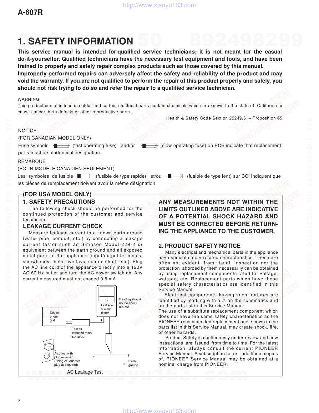
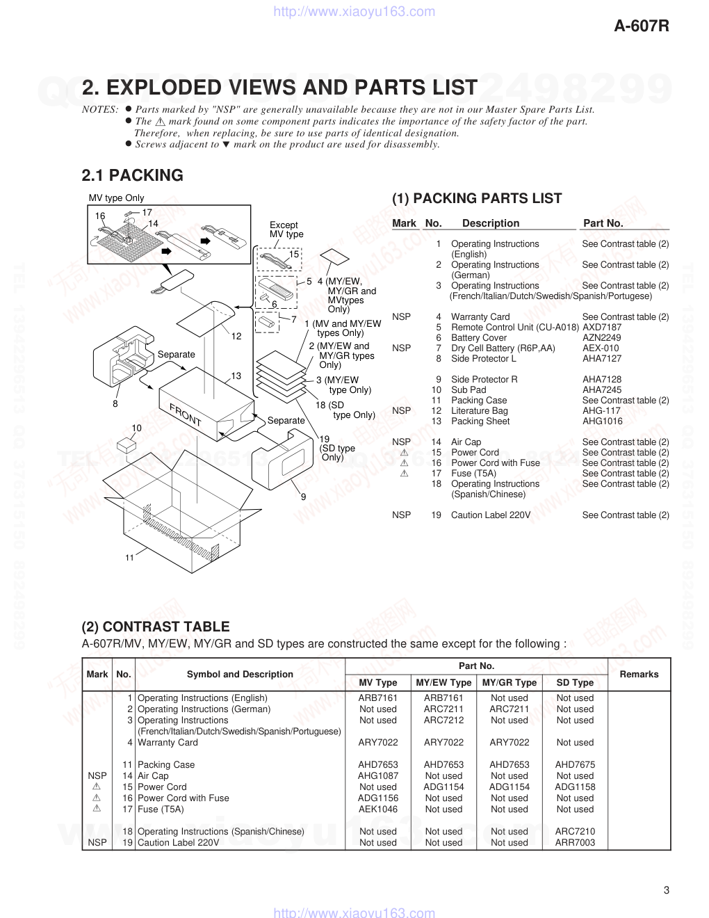
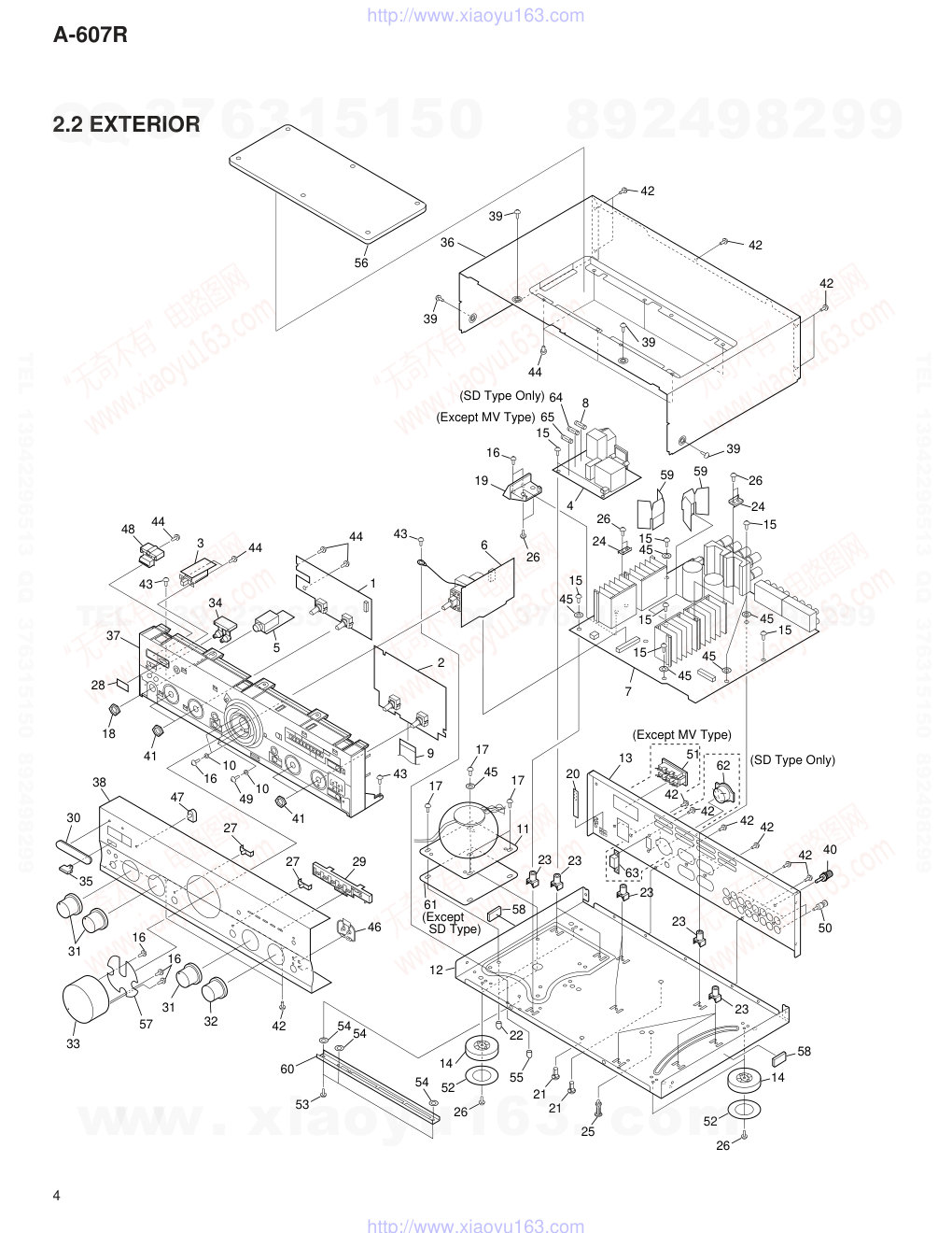
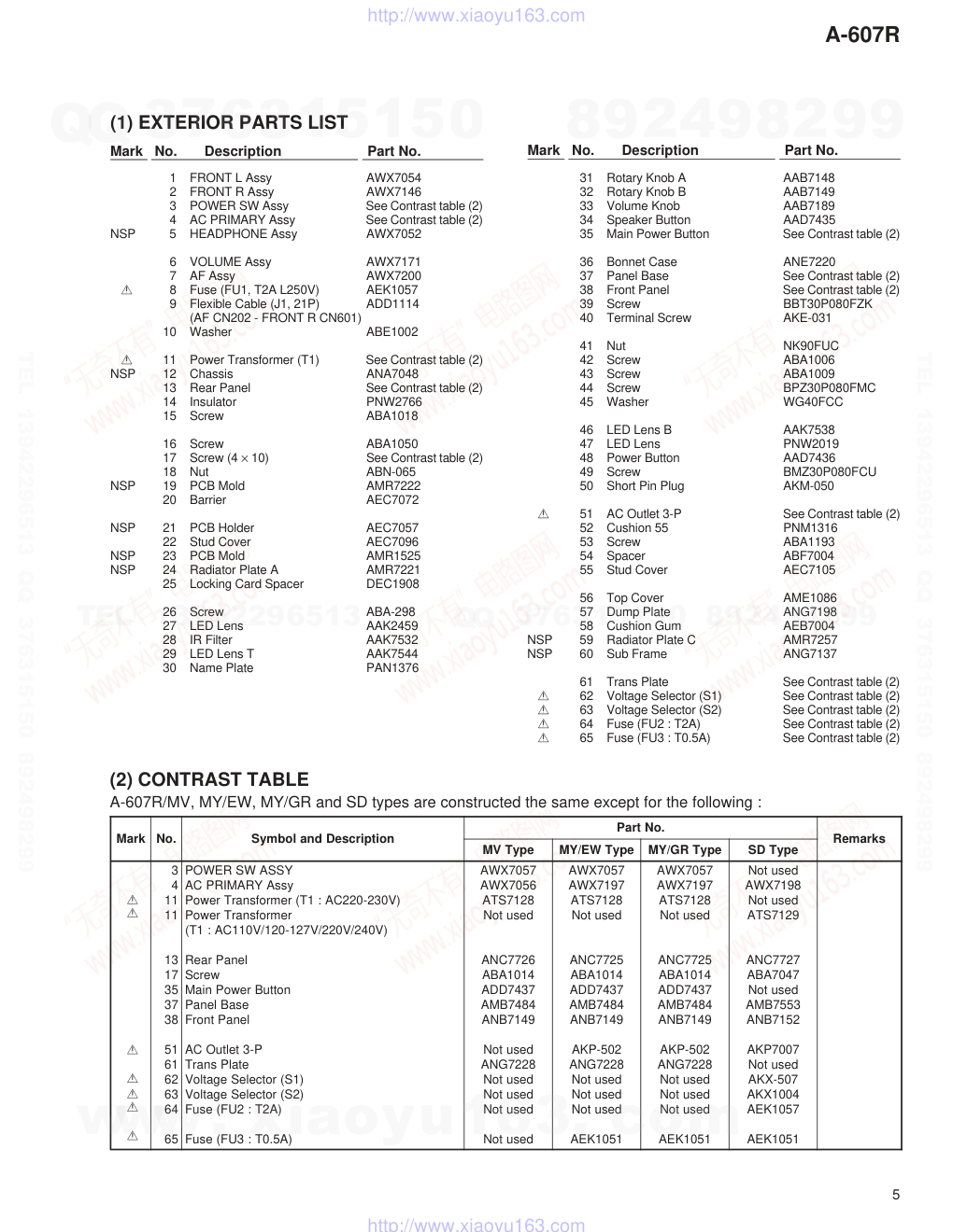
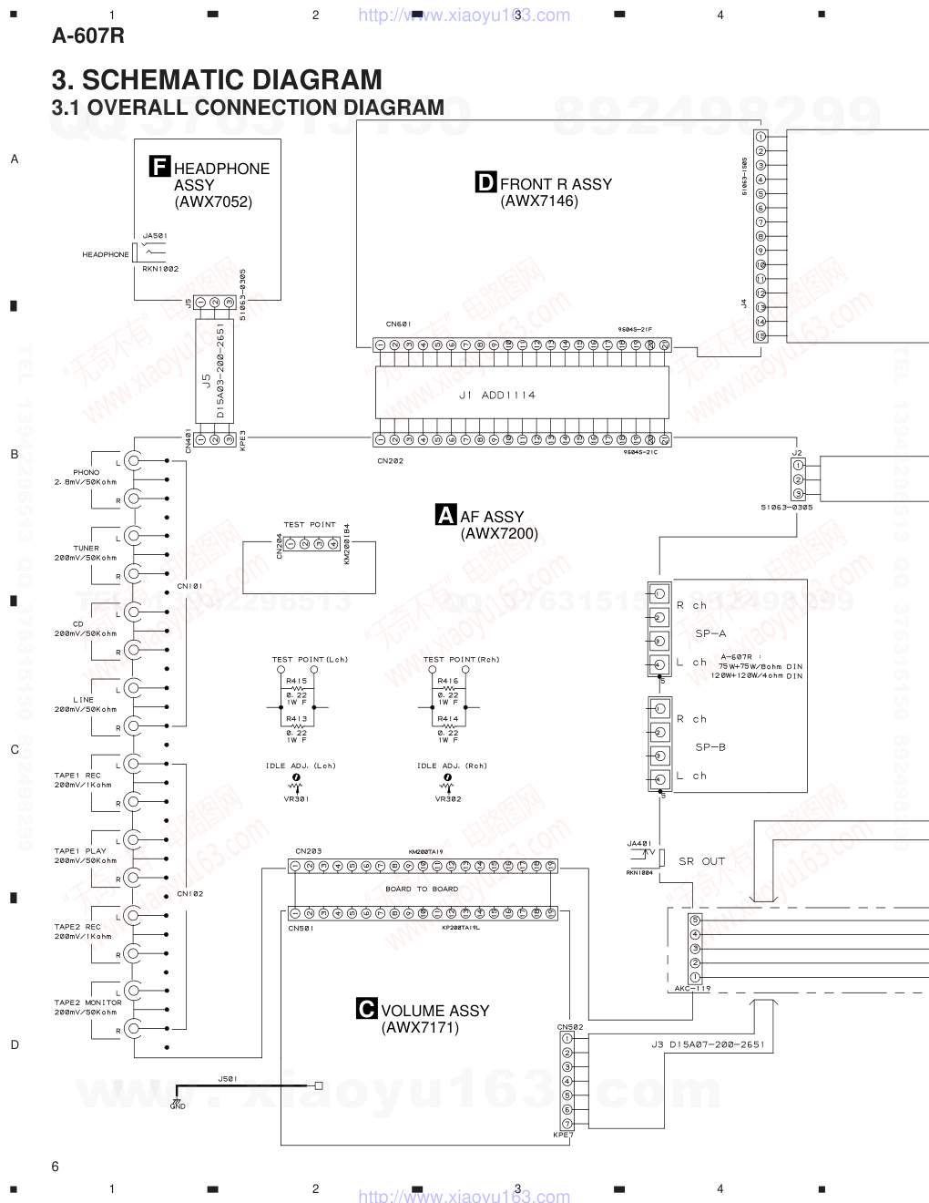
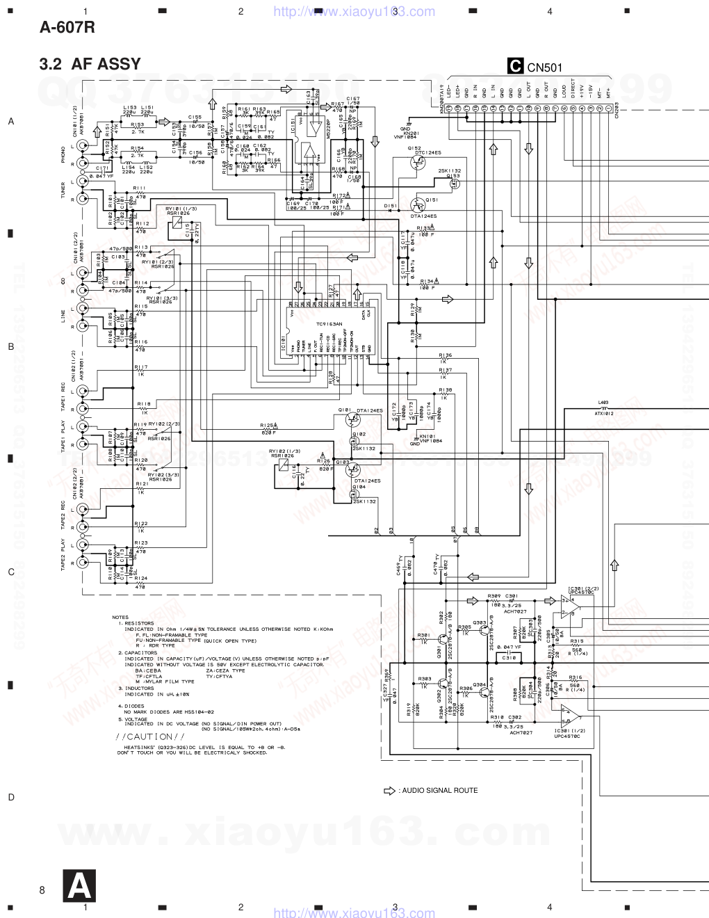
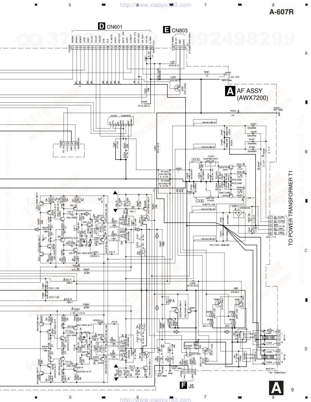
ORDER NO. PIONEER ELECTRONIC CORPORATION 4-1, Meguro 1-Chome, Meguro-ku, Tokyo 153-8654, Japan PIONEER ELECTRONICS SERVICE, INC. P.O. Box 1760, Long Beach, CA 90801-1760, U.S.A. PIONEER ELECTRONIC (EUROPE) N.V. Haven 1087, Keetberglaan 1, 9120 Melsele, Belgium PIONEER ELECTRONICS ASIACENTRE PTE. LTD. 501 Orchard Road, #10-00 Wheelock Place, Singapore 238880 � � � � � � � � � �PIONEER ELECTRONIC CORPORATION 1998 RRV2033 STEREO AMPLIFIER A-607R 1. SAFETY INFORMATION ...................................... 2 2. EXPLODED VIEWS AND PARTS LIST ................ 3 3. SCHEMATIC DIAGRAM ....................................... 6 4. PCB CONNECTION DIAGRAM .......................... 14 5. PCB PARTS LIST ............................................... 19 6. ADJUSTMENT .................................................... 22 CONTENTS 7. GENERAL INFORMATION ................................ 23 7.1 IC INFORMATION ....................................... 23 7.2 BLOCK DIAGRAM ....................................... 24 8. PANEL FACILITIES AND SPECIFICATIONS .... 25 THIS MANUAL IS APPLICABLE TO THE FOLLOWING MODEL(S) AND TYPE(S). Type Model A-607R MV MY/EW MY/GR SD AC220 – 230V AC220 – 230V AC220 – 230V AC110V/120 – 127V/220/240V Power Requirement The voltage can be converted by the following method. ––––––– ––––––– ––––––– With the voltage selector T – ZZK OCT. 1998 Printed in Japan Î� STEREO AMPLIFIER STANDBY/ON STANDBY OFF ON POWER A SPEAKERS B BASS TREBLE PHONES LOUDNESS MIN MAX VOLUME DIRECT BALANCE INPUT SELECTOR REC SELECTOR CD TUNER PHONO LINE TAPE 1 /MD TAPE 2 MONITOR MUTING –20dB CD TUNER OFF SOURCE L R www. xiaoyu163. com QQ 376315150 9 9 2 8 9 4 2 9 8 TEL 13942296513 9 9 2 8 9 4 2 9 8 0 5 1 5 1 3 6 7 3 Q Q TEL 13942296513 QQ 376315150 892498299 TEL 13942296513 QQ 376315150 892498299 http://www.xiaoyu163.com A-607R 2 1. SAFETY INFORMATION This service manual is intended for qualified service technicians; it is not meant for the casual do-it-yourselfer. Qualified technicians have the necessary test equipment and tools, and have been trained to properly and safely repair complex products such as those covered by this manual. Improperly performed repairs can adversely affect the safety and reliability of the product and may void the warranty. If you are not qualified to perform the repair of this product properly and safely, you should not risk trying to do so and refer the repair to a qualified service technician. WARNING This product contains lead in solder and certain electrical parts contain chemicals which are known to the state of California to cause cancer, birth defects or other reproductive harm. Health & Safety Code Section 25249.6 – Proposition 65 NOTICE (FOR CANADIAN MODEL ONLY) Fuse symbols (fast operating fuse) and/or (slow operating fuse) on PCB indicate that replacement parts must be of identical designation. REMARQUE (POUR MODÈLE CANADIEN SEULEMENT) Les symboles de fusible (fusible de type rapide) et/ou (fusible de type lent) sur CCI indiquent que les pièces de remplacement doivent avoir la même désignation. ANY MEASUREMENTS NOT WITHIN THE LIMITS OUTLINED ABOVE ARE INDICATIVE OF A POTENTIAL SHOCK HAZARD AND MUST BE CORRECTED BEFORE RETURN- ING THE APPLIANCE TO THE CUSTOMER. 2. PRODUCT SAFETY NOTICE Many electrical and mechanical parts in the appliance have special safety related characteristics. These are often not evident from visual inspection nor the protection afforded by them necessarily can be obtained by using replacement components rated for voltage, wattage, etc. Replacement parts which have these special safety characteristics are identified in this Service Manual. Electrical components having such features are identified by marking with a on the schematics and on the parts list in this Service Manual. The use of a substitute replacement component which does not have the same safety characteristics as the PIONEER recommended replacement one, shown in the parts list in this Service Manual, may create shock, fire, or other hazards. Product Safety is continuously under review and new instructions are issued from time to time. For the latest information, always consult the current PIONEER Service Manual. A subscription to, or additional copies of, PIONEER Service Manual may be obtained at a nominal charge from PIONEER. (FOR USA MODEL ONLY) 1. SAFETY PRECAUTIONS The following check should be performed for the continued protection of the customer and service technician. LEAKAGE CURRENT CHECK Measure leakage current to a known earth ground (water pipe, conduit, etc.) by connecting a leakage current tester such as Simpson Model 229-2 or equivalent between the earth ground and all exposed metal parts of the appliance (input/output terminals, screwheads, metal overlays, control shaft, etc.). Plug the AC line cord of the appliance directly into a 120V AC 60 Hz outlet and turn the AC power switch on. Any current measured must not exceed 0.5 mA. Device under test Leakage current tester Earth ground Reading should not be above 0.5 mA Also test with plug reversed (Using AC adapter plug as required) Test all exposed metal surfaces AC Leakage Test www. xiaoyu163. com QQ 376315150 9 9 2 8 9 4 2 9 8 TEL 13942296513 9 9 2 8 9 4 2 9 8 0 5 1 5 1 3 6 7 3 Q Q TEL 13942296513 QQ 376315150 892498299 TEL 13942296513 QQ 376315150 892498299 http://www.xiaoyu163.com 3 A-607R 2.1 PACKING Mark No. Description Part No. 2. EXPLODED VIEWS AND PARTS LIST NOTES: • Parts marked by "NSP" are generally unavailable because they are not in our Master Spare Parts List. • The mark found on some component parts indicates the importance of the safety factor of the part. Therefore, when replacing, be sure to use parts of identical designation. • Screws adjacent to mark on the product are used for disassembly. 1 Operating Instructions See Contrast table (2) (English) 2 Operating Instructions See Contrast table (2) (German) 3 Operating Instructions See Contrast table (2) (French/Italian/Dutch/Swedish/Spanish/Portugese) NSP 4 Warranty Card See Contrast table (2) 5 Remote Control Unit (CU-A018) AXD7187 6 Battery Cover AZN2249 NSP 7 Dry Cell Battery (R6P,AA) AEX-010 8 Side Protector L AHA7127 9 Side Protector R AHA7128 10 Sub Pad AHA7245 11 Packing Case See Contrast table (2) NSP 12 Literature Bag AHG-117 13 Packing Sheet AHG1016 NSP 14 Air Cap See Contrast table (2) 15 Power Cord See Contrast table (2) 16 Power Cord with Fuse See Contrast table (2) 17 Fuse (T5A) See Contrast table (2) 18 Operating Instructions See Contrast table (2) (Spanish/Chinese) NSP 19 Caution Label 220V See Contrast table (2) (1) PACKING PARTS LIST (2) CONTRAST TABLE A-607R/MV, MY/EW, MY/GR and SD types are constructed the same except for the following : k r a M . o N n o it p ir c s e D d n a l o b m y S . o N tr a P s k r a m e R e p y T V M e p y T W E / Y M e p y T R G / Y M e p y T D S P S N P S N 1 2 3 4 1 1 4 1 5 1 6 1 7 1 8 1 9 1 ) h silg n E ( s n oitc u rts n I g nit a r e p O ) n a m r e G ( s n oitc u rts n I g nit a r e p O s n oitc u rts n I g nit a r e p O ) e s e u g u tr o P / h sin a p S / h sid e w S / h ct u D / n aila tI/ h c n e r F ( d r a C yt n a rr a W e s a C g nik c a P p a C ri A d r o C r e w o P e s u F h ti w d r o C r e w o P ) A 5 T ( e s u F ( s n oitc u rts n I g nit a r e p O e s e nih C / h sin a p S ) V 0 2 2 le b a L n oit u a C 1 6 1 7 B R A d e s u t o N d e s u t o N 2 2 0 7 Y R A 3 5 6 7 D H A 7 8 0 1 G H A d e s u t o N 6 5 1 1 G D A 6 4 0 1 K E A d e s u t o N d e s u t o N 1 6 1 7 B R A 1 1 2 7 C R A 2 1 2 7 C R A 2 2 0 7 Y R A 3 5 6 7 D H A d e s u t o N 4 5 1 1 G D A d e s u t o N d e s u t o N d e s u t o N d e s u t o N d e s u t o N 1 1 2 7 C R A d e s u t o N 2 2 0 7 Y R A 3 5 6 7 D H A d e s u t o N 4 5 1 1 G D A d e s u t o N d e s u t o N d e s u t o N d e s u t o N d e s u t o N d e s u t o N d e s u t o N d e s u t o N 5 7 6 7 D H A d e s u t o N 8 5 1 1 G D A d e s u t o N d e s u t o N 0 1 2 7 C R A 3 0 0 7 R R A 6 12 14 17 16 13 Separate Separate 8 11 9 5 7 15 MV type Only Except MV type 1 (MV and MY/EW types Only) 3 (MY/EW type Only) 2 (MY/EW and MY/GR types Only) 10 19 (SD type Only) 18 (SD type Only) 4 (MY/EW, MY/GR and MVtypes Only) FRONT www. xiaoyu163. com QQ 376315150 9 9 2 8 9 4 2 9 8 TEL 13942296513 9 9 2 8 9 4 2 9 8 0 5 1 5 1 3 6 7 3 Q Q TEL 13942296513 QQ 376315150 892498299 TEL 13942296513 QQ 376315150 892498299 http://www.xiaoyu163.com 4 A-607R 41 18 28 37 35 34 43 48 44 5 41 16 10 10 49 2 30 31 31 32 38 27 47 27 29 46 22 21 25 21 12 23 23 23 23 23 61 13 20 42 42 42 40 42 7 15 45 4 8 15 15 15 45 45 45 15 15 45 26 15 16 19 6 42 43 9 39 39 39 42 42 42 39 44 56 36 3 44 44 1 33 16 16 57 50 58 58 43 55 14 14 52 26 53 60 52 26 26 24 64 26 24 65 59 59 11 17 45 17 5454 54 17 51 (SD Type Only) (SD Type Only) (Except MV Type) (Except MV Type) (Except SD Type) 62 42 63 2.2 EXTERIOR www. xiaoyu163. com QQ 376315150 9 9 2 8 9 4 2 9 8 TEL 13942296513 9 9 2 8 9 4 2 9 8 0 5 1 5 1 3 6 7 3 Q Q TEL 13942296513 QQ 376315150 892498299 TEL 13942296513 QQ 376315150 892498299 http://www.xiaoyu163.com 5 A-607R 1 FRONT L Assy AWX7054 2 FRONT R Assy AWX7146 3 POWER SW Assy See Contrast table (2) 4 AC PRIMARY Assy See Contrast table (2) NSP 5 HEADPHONE Assy AWX7052 6 VOLUME Assy AWX7171 7 AF Assy AWX7200 8 Fuse (FU1, T2A L250V) AEK1057 9 Flexible Cable (J1, 21P) ADD1114 (AF CN202 - FRONT R CN601) 10 Washer ABE1002 11 Power Transformer (T1) See Contrast table (2) NSP 12 Chassis ANA7048 13 Rear Panel See Contrast table (2) 14 Insulator PNW2766 15 Screw ABA1018 16 Screw ABA1050 17 Screw (4 × 10) See Contrast table (2) 18 Nut ABN-065 NSP 19 PCB Mold AMR7222 20 Barrier AEC7072 NSP 21 PCB Holder AEC7057 22 Stud Cover AEC7096 NSP 23 PCB Mold AMR1525 NSP 24 Radiator Plate A AMR7221 25 Locking Card Spacer DEC1908 26 Screw ABA-298 27 LED Lens AAK2459 28 IR Filter AAK7532 29 LED Lens T AAK7544 30 Name Plate PAN1376 Mark No. Description Part No. Mark No. Description Part No. (1) EXTERIOR PARTS LIST 31 Rotary Knob A AAB7148 32 Rotary Knob B AAB7149 33 Volume Knob AAB7189 34 Speaker Button AAD7435 35 Main Power Button See Contrast table (2) 36 Bonnet Case ANE7220 37 Panel Base See Contrast table (2) 38 Front Panel See Contrast table (2) 39 Screw BBT30P080FZK 40 Terminal Screw AKE-031 41 Nut NK90FUC 42 Screw ABA1006 43 Screw ABA1009 44 Screw BPZ30P080FMC 45 Washer WG40FCC 46 LED Lens B AAK7538 47 LED Lens PNW2019 48 Power Button AAD7436 49 Screw BMZ30P080FCU 50 Short Pin Plug AKM-050 51 AC Outlet 3-P See Contrast table (2) 52 Cushion 55 PNM1316 53 Screw ABA1193 54 Spacer ABF7004 55 Stud Cover AEC7105 56 Top Cover AME1086 57 Dump Plate ANG7198 58 Cushion Gum AEB7004 NSP 59 Radiator Plate C AMR7257 NSP 60 Sub Frame ANG7137 61 Trans Plate See Contrast table (2) 62 Voltage Selector (S1) See Contrast table (2) 63 Voltage Selector (S2) See Contrast table (2) 64 Fuse (FU2 : T2A) See Contrast table (2) 65 Fuse (FU3 : T0.5A) See Contrast table (2) (2) CONTRAST TABLE A-607R/MV, MY/EW, MY/GR and SD types are constructed the same except for the following : k r a M . o N n o it p ir c s e D d n a l o b m y S . o N tr a P s k r a m e R e p y T V M e p y T W E / Y M e p y T R G / Y M e p y T D S 3 4 1 1 1 1 3 1 7 1 5 3 7 3 8 3 1 5 1 6 2 6 3 6 4 6 5 6 Y S S A W S R E W O P y s s A Y R A M I R P C A ) V 0 3 2 - 0 2 2 C A : 1 T ( r e m r o fs n a r T r e w o P r e m r o fs n a r T r e w o P ) V 0 4 2 / V 0 2 2 / V 7 2 1 - 0 2 1 / V 0 1 1 C A : 1 T ( le n a P r a e R w e r c S n o tt u B r e w o P nia M e s a B le n a P le n a P t n o r F P - 3 t elt u O C A e t al P s n a r T ) 1 S ( r o tc ele S e g a tlo V ) 2 S ( r o tc ele S e g a tlo V ) A 2 T : 2 U F ( e s u F ) A 5 . 0 T : 3 U F ( e s u F 7 5 0 7 X W A 6 5 0 7 X W A 8 2 1 7 S T A d e s u t o N 6 2 7 7 C N A 4 1 0 1 A B A 7 3 4 7 D D A 4 8 4 7 B M A 9 4 1 7 B N A d e s u t o N 8 2 2 7 G N A d e s u t o N d e s u t o N d e s u t o N d e s u t o N 7 5 0 7 X W A 7 9 1 7 X W A 8 2 1 7 S T A d e s u t o N 5 2 7 7 C N A 4 1 0 1 A B A 7 3 4 7 D D A 4 8 4 7 B M A 9 4 1 7 B N A 2 0 5 - P K A 8 2 2 7 G N A d e s u t o N d e s u t o N d e s u t o N 1 5 0 1 K E A 7 5 0 7 X W A 7 9 1 7 X W A 8 2 1 7 S T A d e s u t o N 5 2 7 7 C N A 4 1 0 1 A B A 7 3 4 7 D D A 4 8 4 7 B M A 9 4 1 7 B N A 2 0 5 - P K A 8 2 2 7 G N A d e s u t o N d e s u t o N d e s u t o N 1 5 0 1 K E A d e s u t o N 8 9 1 7 X W A d e s u t o N 9 2 1 7 S T A 7 2 7 7 C N A 7 4 0 7 A B A d e s u t o N 3 5 5 7 B M A 2 5 1 7 B N A 7 0 0 7 P K A d e s u t o N 7 0 5 - X K A 4 0 0 1 X K A 7 5 0 1 K E A 1 5 0 1 K E A www. xiaoyu163. com QQ 376315150 9 9 2 8 9 4 2 9 8 TEL 13942296513 9 9 2 8 9 4 2 9 8 0 5 1 5 1 3 6 7 3 Q Q TEL 13942296513 QQ 376315150 892498299 TEL 13942296513 QQ 376315150 892498299 http://www.xiaoyu163.com A-607R 6 A B C D 1 2 3 4 1 2 3 4 A AF ASSY D FRONT R ASSY F HEADPHONE ASSY C VOLUME ASSY (AWX7052) (AWX7200) (AWX7146) (AWX7171) 3. SCHEMATIC DIAGRAM 3.1 OVERALL CONNECTION DIAGRAM www. xiaoyu163. com QQ 376315150 9 9 2 8 9 4 2 9 8 TEL 13942296513 9 9 2 8 9 4 2 9 8 0 5 1 5 1 3 6 7 3 Q Q TEL 13942296513 QQ 376315150 892498299 TEL 13942296513 QQ 376315150 892498299 http://www.xiaoyu163.com A-607R 7 A B C D 5 6 7 8 5 6 7 8 B FRONT L ASSY E AC PRIMARY ASSY (AWX7054) (AWX7057) (MY/EW, MY/GR : AWX7197) (MV : AWX7056) (SD : AWX7198) G POWER SW ASSY EXCEPT SD TYPE (SD ONLY) (MY/EW, MY/GR ONLY) AC PRIMARY ASSY Note : When ordering service parts, be sure to refer to "EXPLODED VIEWS and PARTS LIST" or "PCB PARTS LIST". www. xiaoyu163. com QQ 376315150 9 9 2 8 9 4 2 9 8 TEL 13942296513 9 9 2 8 9 4 2 9 8 0 5 1 5 1 3 6 7 3 Q Q TEL 13942296513 QQ 376315150 892498299 TEL 13942296513 QQ 376315150 892498299 http://www.xiaoyu163.com A-607R 8 A B C D 1 2 3 4 1 2 3 4 C CN501 : AUDIO SIGNAL ROUTE 3.2 AF ASSY A www. xiaoyu163. com QQ 376315150 9 9 2 8 9 4 2 9 8 TEL 13942296513 9 9 2 8 9 4 2 9 8 0 5 1 5 1 3 6 7 3 Q Q TEL 13942296513 QQ 376315150 892498299 TEL 13942296513 QQ 376315150 892498299 http://www.xiaoyu163.com A-607R 9 A B C D 5 6 7 8 5 6 7 8 A AF ASSY D CN601 E CN803 F J5 TO POWER TRANSFORMER T1 (AWX7200) L406 ATX1012 A www. xiaoyu163. com QQ 376315150 9 9 2 8 9 4 2 9 8 TEL 13942296513 9 9 2 8 9 4 2 9 8 0 5 1 5 1 3 6 7 3 Q Q TEL 13942296513 QQ 376315150 892498299 TEL 13942296513 QQ 376315150 892498299 http://www.xiaoyu163.com A-607R 10 A B C D 1 2 3 4 1 2 3 4 B FRONT L ASSY D J4 FRONT L ASSY S 701 : POWER STANDBY/ON S 702 : LOUDNESS S 703 : SPEAKERS A S 704 : SPEAKERS B (AWX7054) 3.3 FRONT L AND VOLUME ASSEMBLIES B www. xiaoyu163. com QQ 376315150 9 9 2 8 9 4 2 9 8 TEL 13942296513 9 9 2 8 9 4 2 9 8 0 5 1 5 1 3 6 7 3 Q Q TEL 13942296513 QQ 376315150 892498299 TEL 13942296513 QQ 376315150 892498299 http://www.xiaoyu163.com A-607R 11 A B C D 5 6 7 8 5 6 7 8 : AUDIO SIGNAL ROUTE C VOLUME ASSY A CN203 (AWX7171) C www. xiaoyu163. com QQ 376315150 9 9 2 8 9 4 2 9 8 TEL 13942296513 9 9 2 8 9 4 2 9 8 0 5 1 5 1 3 6 7 3 Q Q TEL 13942296513 QQ 376315150 892498299 TEL 13942296513 QQ 376315150 892498299 http://www.xiaoyu163.com A-607R 12 A B C D 1 2 3 4 1 2 3 4 E AC PRIMARY ASSY A J2 TO POWER TRANSFORMER T1 • NOTE FOR FUSE REPLACEMENT FOR CONTINUED PROTECTION AGAINST RISK OF FIRE. REPLACE WITH SAME TYPE AND RATINGS ONLY. CAUTION - 1/50 YA NP (MY/EW, MY/GR : AWX7197) (MV : AWX7056) (SD : AWX7198) TO VOLTAGE SELECTOR (SD ONLY) RY801 : ASR1036 (SD) FU1 T2A L 250V AEK1057 FU2 SD ONLY T2A L 250V AEK1057 FU3 (EXCEPT MV) T0.5A L 250V AEK1051 SD ONLY (AKC-081) SWITCHED UNSWITCHED TO AC OUTLET (EXCEPT MV) (EXCEPT SD) 240V 120V N AC POWER CORD 47/10 D FRONT R ASSY (AWX7146) 3.4 FRONT R, AC PRIMARY, HEADPHONE AND POWER SW ASSEMBLIES D E www. xiaoyu163. com QQ 376315150 9 9 2 8 9 4 2 9 8 TEL 13942296513 9 9 2 8 9 4 2 9 8 0 5 1 5 1 3 6 7 3 Q Q TEL 13942296513 QQ 376315150 892498299 TEL 13942296513 QQ 376315150 892498299 http://www.xiaoyu163.com A-607R 13 A B C D 5 6 7 8 5 6 7 8 F HEADPHONE ASSY (AWX7052) A CN401 G POWER SW ASSY (AWX7057) EXCEPT SD TYPE A CN202 B CN701 FRONT R ASSY S 601 : INPUT SELECTOR S 603 : TAPE2 MONITOR S 604 : DIRECT S 606 : REC SELECTOR TC74HC107AP TC74HC00AP S 605 : MUTING G F D www. xiaoyu163. com QQ 376315150 9 9 2 8 9 4 2 9 8 TEL 13942296513 9 9 2 8 9 4 2 9 8 0 5 1 5 1 3 6 7 3 Q Q TEL 13942296513 QQ 376315150 892498299 TEL 13942296513 QQ 376315150 892498299 http://www.xiaoyu163.com A-607R 14 A B C D 1 2 3 4 1 2 3 4 A SIDE A AF ASSY A J5 F CN501 C CN803 E POWER TRANSFORMER T1 NOTE FOR PCB DIAGRAMS: 1. Part numbers in PCB diagrams match those in the schematic diagrams. 2. A comparison between the main parts of PCB and schematic diagrams is shown below. 3. The parts mounted on this PCB include all necessary parts for several destination. For further information for respective destinations, be sure to check with the schematic diagram. 4. Viewpoint of PCB diagrams Symbol in PCB Diagrams Symbol in Schematic Diagrams Part Name Transistor Transistor with resistor Field effect transistor MOS Field effect transistor Resistor array 3-terminal regulator B C E B C E B C E D D 2 1 3 G G G S S S B C E B C E B C E D G S D G S D G S Capacitor Connector P.C.Board Chip Part SIDE A SIDE B D G S 4. PCB CONNECTION DIAGRAM 4.1 AF ASSY www. xiaoyu163. com QQ 376315150 9 9 2 8 9 4 2 9 8 TEL 13942296513 9 9 2 8 9 4 2 9 8 0 5 1 5 1 3 6 7 3 Q Q TEL 13942296513 QQ 376315150 892498299 TEL 13942296513 QQ 376315150 892498299 http://www.xiaoyu163.com A-607R 15 A B C D 5 6 7 8 5 6 7 8A CN601 D Q401 Q406 Q413 Q414 Q451 Q452 Q409 Q411 Q323 Q319 Q322 Q412 Q410 Q407 Q408 Q324 IC451 IC151 IC452 IC101 Q313 VR301 VR302 Q318 Q301 Q304 Q251 Q309 Q312 Q325 Q334 IC301 IC251 (ANP7227-A) Q101 Q104 Q151 Q153 www. xiaoyu163. com QQ 376315150 9 9 2 8 9 4 2 9 8 TEL 13942296513 9 9 2 8 9 4 2 9 8 0 5 1 5 1 3 6 7 3 Q Q TEL 13942296513 QQ 376315150 892498299 TEL 13942296513 QQ 376315150 892498299 http://www.xiaoyu163.com A-607R 16 A B C D 1 2 3 4 1 2 3 4 B C FRONT L ASSY B VOLUME ASSY (ANP7227-A) (ANP7227-A) Q705 VR751 VR752 Q704 Q701 Q702 Q707 Q706 Q703 IC751 Q751 Q502 Q501 Q503 Q507 Q509 Q505 Q510 Q511 Q506 Q504 Q508 Q513 Q512 Q514 Q752 C CN203 A J4 D 4.2 FRONT L AND VOLUME ASSEMBLIES SIDE A www. xiaoyu163. com QQ 376315150 9 9 2 8 9 4 2 9 8 TEL 13942296513 9 9 2 8 9 4 2 9 8 0 5 1 5 1 3 6 7 3 Q Q TEL 13942296513 QQ 376315150 892498299 TEL 13942296513 QQ 376315150 892498299 http://www.xiaoyu163.com A-607R 17 A B C D 1 2 3 4 1 2 3 4D 4.3 FRONT R ASSY FRONT R ASSY D CN202 A CN701 (ANP7228-A) B J4 Q616 Q606 Q610 Q617 IC603 Q608 Q609 Q605 Q604 IC601 Q603 Q602 Q601 Q612 Q613 Q614 Q611 Q615 Q607 VR601 IC602 Q618 SIDE A www. xiaoyu163. com QQ 376315150 9 9 2 8 9 4 2 9 8 TEL 13942296513 9 9 2 8 9 4 2 9 8 0 5 1 5 1 3 6 7 3 Q Q TEL 13942296513 QQ 376315150 892498299 TEL 13942296513 QQ 376315150 892498299 http://www.xiaoyu163.com A-607R 18 A B C D 1 2 3 4 1 2 3 4 E F G 4.4 AC PRIMARY, HEADPHONE AND POWER SW ASSEMBLIES J2 (ANP7228-A) (ANP7228-A) (ANP7228-A) A AC POWER CORD AC OUTLET (EXCEPT MV) VOLTAGE SELECTOR (SD ONLY) (EXCEPT SD) CN401 A AC PRIMARY ASSY E HEADPHONE ASSY F POWER SW ASSY G Q811 IC811 POWER TRANSFORMER T1 LIVE NEUTRAL VOLTAGE SELECTOR (SD ONLY) SIDE A www. xiaoyu163. com QQ 376315150 9 9 2 8 9 4 2 9 8 TEL 13942296513 9 9 2 8 9 4 2 9 8 0 5 1 5 1 3 6 7 3 Q Q TEL 13942296513 QQ 376315150 892498299 TEL 13942296513 QQ 376315150 892498299 http://www.xiaoyu163.com 19 A-607R Mark No. Description Part No. Mark No. Description Part No. AF ASSY SEMICONDUCTORS IC151 M5220P IC451 NJM78M15FA IC452 NJM79L15A IC251 TA8409S IC101 TC9163AN IC301 UPC4570C Q327, Q328, Q409, Q410 2SA1048 Q321, Q322 2SA970 Q311–Q314, Q329, Q330 2SA992 Q452 2SB1238X Q309, Q310, Q315, Q316 2SC1845 Q333, Q334 2SC1845 Q319, Q320 2SC2240 Q317, Q318, Q331, Q332 2SC2458 Q407, Q408 2SC2458 Q301–Q304 2SC2878 Q451 2SC4793 Q102, Q104, Q153, Q403–Q406 2SK1132 Q414 2SK1132 Q401, Q402, Q413 DTA114ES Q101, Q103, Q151 DTA124ES Q152, Q251 DTC124ES Q411, Q412 DTC143ES Q323, Q324 IRF540 Q325, Q326 IRF9540 Mark No. Description Part No. Mark No. Description Part No. 5. PCB PARTS LIST NOTES: •Parts marked by "NSP" are generally unavailable because they are not in our Master Spare Parts List. •The mark found on some component parts indicates the importance of the safety factor of the part. Therefore, when replacing, be sure to use parts of identical designation. •When ordering resistors, first convert resistance values into code form as shown in the following examples. Ex.1 When there are 2 effective digits (any digit apart from 0), such as 560 ohm and 47k ohm (tolerance is shown by J=5%, and K=10%). 560 Ω → 56 × 10 1 → 561 ........................................................ RD1/4PU 5 6 1 J 47k Ω → 47 × 10 3 → 473 ........................................................ RD1/4PU 4 7 3 J 0.5 Ω → R50 ..................................................................................... RN2H R 5 0 K 1 Ω → 1R0 ..................................................................................... RS1P 1 R 0 K Ex.2 When there are 3 effective digits (such as in high precision metal film resistors). 5.62k Ω → 562 × 10 1 → 5621 ...................................................... RN1/4PC 5 6 2 1 F k r a M n o it p ir c s e D d n a l o b m y S . o N tr a P s k r a m e R e p y T V M e p y T W E / Y M e p y T R G / Y M e p y T D S P S N P S N P S N Y S S A X E L P M O C F A Y S S A F A Y S S A L T N O R F Y S S A E M U L O V Y S S A L O R T N O C Y S S A R T N O R F Y S S A Y R A M I R P C A Y S S A E N O H P D A E H Y S S A W S R E W O P 8 6 4 7 K W A 0 0 2 7 X W A 4 5 0 7 X W A 1 7 1 7 X W A 7 1 0 7 G W A 6 4 1 7 X W A 6 5 0 7 X W A 2 5 0 7 X W A 7 5 0 7 X W A 8 6 4 7 K W A 0 0 2 7 X W A 4 5 0 7 X W A 1 7 1 7 X W A 5 1 0 7 G W A 6 4 1 7 X W A 7 9 1 7 X W A 2 5 0 7 X W A 7 5 0 7 X W A 8 6 4 7 K W A 0 0 2 7 X W A 4 5 0 7 X W A 1 7 1 7 X W A 5 1 0 7 G W A 6 4 1 7 X W A 7 9 1 7 X W A 2 5 0 7 X W A 7 5 0 7 X W A 8 6 4 7 K W A 0 0 2 7 X W A 4 5 0 7 X W A 1 7 1 7 X W A 6 1 0 7 G W A 6 4 1 7 X W A 8 9 1 7 X W A 2 5 0 7 X W A d e s u t o N LIST OF WHOLE PCB ASSEMBLIES A D451 D5SBA20 D151, D201, D202, D301–D306 HSS104-02 D309–D314 HSS104-02 D307, D308 HZS9A1L D454 MTZJ33B D453 MTZJ36B D455 MTZJ4.7A D457–D460 S5688G COILS AND FILTERS L201, L202, L401, L403 ATX1012 L405, L406 ATX1012 L151–L154 LAU221J SWITCHES AND RELAYS RY403 ASR1035 RY401, RY402 ASR7014 RY101, RY102 RSR1026 CAPACITORS C461 (1µF/100V) ACH1237 C301, C302, C457, C458 ACH7027 (3.3µF/25V) C451 (15000µF/50V) ACH7087 C452 (15000µF/50V) ACH7088 C101, C102, C105, C106 CCCSL101J50 C109, C110, C113, C114 CCCSL101J50 C153, C154 CCCSL221J50 C303, C304 CCCSL221K2H C313–C316 CCCSL330K2H C163, C164 CCCSL390J50 www. xiaoyu163. com QQ 376315150 9 9 2 8 9 4 2 9 8 TEL 13942296513 9 9 2 8 9 4 2 9 8 0 5 1 5 1 3 6 7 3 Q Q TEL 13942296513 QQ 376315150 892498299 TEL 13942296513 QQ 376315150 892498299 http://www.xiaoyu163.com 20 A-607R Mark No. Description Part No. Mark No. Description Part No. CN204 4P PLUG KM200IB4 CN203 19P PLUG KM200TA19 CN401 CONNECTOR (3P) KPE3 JA401 REMOTE CONTROL JACK RKN1004 PCB BINDER VEF1040 KN101, KN201, KN301, KN302 VNF1084 KN451 EARTH METAL FITTING VNF1084 FRONT L ASSY SEMICONDUCTORS IC751 UPC4570C Q751, Q752 2SC1845 Q702, Q703 2SC2458 Q701, Q704–Q707 DTC124ES D702, D711 HSS104-02 D701, D704–D706 SLR-342VCT31 SWITCHES AND RELAYS S701–S704 ASG1034 CAPACITORS C701 (3.3µF/25V) ACH7027 C753, C754 CCCSL151J50 C751, C752, C755, C756 CEAS100M50 C759, C760 CEASR47M50 C761, C762 CEJAR10M50 C757, C758 CFTLA153J50 C765 CKCYF473Z50 C763, C764 CKPUYB102K50 C711 CKPUYF473Z16 RESISTORS R771, R772 RD1/4MUF101J VR751, VR752 (30kΩ) ACS7016 Other Resistors RD1/4PU J OTHERS CABLE HOLDER (7P) 51063-0705 J3 JUMPER WIRE D15A07-200-2651 CN701 CONNECTOR (15P) KPE15 REMOTE RECEIVER UNIT GP1U28X VOLUME ASSY SEMICONDUCTORS Q501–Q510 2SK246 Q512 DTA124ES Q511, Q513, Q514 DTC124ES D501–D510, D512, D513 HSS104-02 CAPACITORS C501, C502 CCCSL471J50 C512 CEBA470M10 C503, C504 CFTYA823J50 C511 CKCYF473Z50 RESISTORS VR501 (50kΩ) ACX1090 Other Resistors RD1/4PU J OTHERS CN501 19P SOCKET KP200TA19L CN502 CONNECTOR (7P) KPE7 C B C103, C104 CCCSL470K2H C167, C168 CEANP1R0M50 C408 CEANP470M10 C155, C156, C465, C466 CEAS100M50 C169, C170 CEAS101M25 C467, C468 CEAS2R2M2A C251 CEAS470M25 C157, C158 CEAS471M6R3 C305, C306, C455, C456, C463 CEBA100M50 C405–C407 CEBA2R2M50 C317, C318 CEBA470M50 C325, C326 CEBAR47M50 C459, C460 CEZA102M50 C319, C320 CEZA470M50 C115, C116, C201, C321–C324 CFTYA224J50 C161, C162, C469, C470 CFTYA823J50 C165, C166 CKCYB222K50 C401–C404 CKCYB332K2H C117, C118, C171, C310, C327 CKCYF473Z50 C409, C453, C454 CKCYF473Z50 C172–C174 CKPUYB102K50 C159, C160 CQMA243J50 C307, C308 PCH1128 RESISTORS R458, R459 RD1/4LMF2R2J R133, R134, R171, R172 RD1/4MUF101J R317, R318, R351–R354, R417 RD1/4MUF101J R452 RD1/4MUF101J R339–R346 RD1/4MUF221J R331–R334 RD1/4MUF391J R125, R126 RD1/4MUF821J R367, R368 RD1/4PMF100J R355, R356 RD1/4PMF222J R461 RD1/4PMF470J R361, R362 RD1/4PMF4R7J R462 RD1/4PU100J R363, R364 RDR1/2PM152J R315, R316 RDR1/4PM561J R357–R360 RFA1/4PS101J R349, R350 RN1/4PC2001F R451 RS1LMF330J R413–R416 RS1LMFR22J R453 RS2LMF122J R454 RS2LMF182J R403, R404 RS2LMF331J VR301, VR302 (2.2kΩ) VCP1123 Other Resistors RD1/4PU J OTHERS CABLE HOLDER (3P) 51063-0305 CN202 21P FFC CONNECTOR 9604S-21C SCREW ABA-298 SCREW ABA1007 SCREW ABA1052 CN101, CN102 PIN JACK(8P) AKB7081 SPEAKER TERMINAL 8-P AKE1011 HEAT SINK B ANH1021 HEAT SINK ANH1150 J2 JUMPER WIRE D15A03-075-2651 www. xiaoyu163. com QQ 376315150 9 9 2 8 9 4 2 9 8 TEL 13942296513 9 9 2 8 9 4 2 9 8 0 5 1 5 1 3 6 7 3 Q Q TEL 13942296513 QQ 376315150 892498299 TEL 13942296513 QQ 376315150 892498299 http://www.xiaoyu163.com 21 A-607R Mark No. Description Part No. Mark No. Description Part No. FRONT R ASSY SEMICONDUCTORS IC601 PD5369A IC603 TC74HC00AP IC602 TC74HC107AP Q609 2SA1048 Q607, Q610, Q618 2SC2458 Q611–Q613, Q615, Q616 DTA124ES Q601–Q606, Q608, Q614, Q617 DTC124ES D608–D610, D615, D618–D622 HSS104-02 D636 HSS104-02 D631 MTZJ2.2B D617 MTZJ4.3A D607 SLR-342DCT31 D601–D606, D632–D635 SLR-342VCT31 COILS AND FILTERS L601–L609 LAU221J SWITCHES AND RELAYS S603–S606 ASG1034 S601 ASX7002 CAPACITORS C601, C625, C635 (3.3µF/25V) ACH7027 C605 (0.22F) ACH7058 C624 CEJA1R0M50 C610, C637 CEJA2R2M50 C634 CEJA3R3M50 C603 CEJA470M16 C604 CKCYF103Z50 C613–C623, C626, C627, C630 CKPUYF103Z25 C632, C633 CKPUYF103Z25 C628, C629, C631 CKPUYF473Z16 C609, C636 CKPUYX472M16 RESISTORS VR601 (500KΩ) ACS7019 Other Resistors RD1/4PU J OTHERS CABLE HOLDER (15P) 51063-1505 CN601 21P FFC CONNECTOR 9604S-21F J4 JUMPER WIRE D15A15-125-2651 X601 CERAMIC RESONATOR VSS1014 (4.19MHz) AC PRIMARY ASSY (1) CONTRAST TABLE AWX7056, AWX7197 and AWX7198 are constructed the same except for the following : Mark Symbol and Description Part No. Remarks AWX7056 AWX7197 AWX7198 H3, H4 FUSE HOLDER Not used Not used RKR1003 H5, H6 FUSE HOLDER Not used RKR1003 RKR1003 RY801 RSR1037 RSR1037 ASR1036 (2) PARTS LIST FOR AWX7056 SEMICONDUCTORS IC811 NJM78M56FA Q811 2SK1132 D815 HSS104-02 D811–D814 S5688G TRANSFORMERS T801 ATT7009 SWITCHES AND RELAYS RY801 RSR1037 CAPACITORS C801, C802 (0.01µF/AC250V) ACG7020 C815 (3.3µF/25V) ACH7027 C813 CEAT471M25 C814 CEBA470M10 C811 CEYANP1R0M50 RESISTORS Other Resistors RD1/4PU J OTHERS Y802, Y803 BOARDIN READ WIRE ADX7207 CN801 AC INLET AKP7005 CN803 CONNECTOR (3P) KPE3 H1, H2 FUSE HOLDER RKR1003 HEADPHONE ASSY CAPACITORS C551, C552 CKCYB392K50 OTHERS CABLE HOLDER (3P) 51063-0305 J5 JUMPER WIRE D15A03-150-2651 JA501 HEADPHONE JACK RKN1002 POWER SW ASSY SWITCHES AND RELAYS S901 ASG1035 CAPACITORS C901 (0.0033µF/AC250V) ACG7017 F G D E www. xiaoyu163. com QQ 376315150 9 9 2 8 9 4 2 9 8 TEL 13942296513 9 9 2 8 9 4 2 9 8 0 5 1 5 1 3 6 7 3 Q Q TEL 13942296513 QQ 376315150 892498299 TEL 13942296513 QQ 376315150 892498299 http://www.xiaoyu163.com A-607R 22 6. ADJUSTMENTS 6.1 IDLE CURRENT ADJUSTMENT ¶ CAUTION : Heatsinks’ (Q323–Q326) DC level is equal to +B or -B. Don’t touch them or you will be electricary chocked. 1. Connect the measuring instrument as Fig.6-1. (R415 or R416) 2. Set the VOLUME CONTROL to minimum, BASS TONE CONTROL to center, TREBLE TONE CONTROL to center and BALANCE CONTROL to center. Set VR301 and VR302 to minimum. 3. Set the POWER switch to ON. 4. Adjust VR301 (VR302) so that the voltage between both sides of R415 (R416) becomes 16mV±1mV. (Within 10 seconds from when the relay is turned ON) 5. Ages for 7 minutes. 6. Adjust VR301 (VR302) so that the voltage between both sides of R415 (R416) becomes 11mV±1mV. VR301 VR302 R413 R414 R415 R416 Heat Sink CN204 AF ASSY DC Voltmeter DC Voltmeter SIDE A Heat Sink Heat Sink Heat Sink R417 W212 W150 Fig.6-1 Adjustment Method www. xiaoyu163. com QQ 376315150 9 9 2 8 9 4 2 9 8 TEL 13942296513 9 9 2 8 9 4 2 9 8 0 5 1 5 1 3 6 7 3 Q Q TEL 13942296513 QQ 376315150 892498299 TEL 13942296513 QQ 376315150 892498299 http://www.xiaoyu163.com A-607R 23 • The information shown in the list is basic information and may not correspond exactly to that shown in the schematic diagrams. No. Pin name I/O Function 1 P53 I Remote control signal input pin. 2 P17/SRDY O STB for TC9163N. 3 P16/CLK O CLOCK for TC9163N. 4 P15/SOUT O DATA for TC9163N. 5 P14/SIN O CD INDICATOR. 6 P13/T1 O TUNER INDICATOR. 7 P12/T0 O PHONO INDICATOR. 8 P11 O LINE INDICATOR. 9 P10 O TAPE1 INDICATOR. 10 P27/IN7 O SPEAKER-A INDICATOR. 11 P26/IN6 O SPEAKER-B INDICATOR. 12 P25/IN5 O LOUDNESS INDICATOR. 13 P24/IN4 O POWER (STAND-BY) INDICATOR. MUTE INDICATOR. 14 P23/IN3 O MUTE ON : Repeats H and L every 1 second. Normal : “H” 15 P22/IN2 O DIRECT INDICATOR. 16 P21/IN1 O TAPE2 INDICATOR. 17 P20/IN0 O FUNCTION switch MUTE. 18 VREF I Pulls up to 5V. 19 XIN I 4.19MHz . 20 XOUT O Ceramic vibrating and connecting terminal. 21 VSS - Digatal GND. 22 VCC - Power supply +5V. 23 P50/XCIN I SPEAKER-B KEY input. No. Pin name I/O Function 24 P51/XCOUT I SPEAKER-A KEY input. 25 RESET I Reset pin. 26 P30/INT0 I BACK UP detection pin. interrupt specification. 27 P31/INT1 O Not used. 28 P32/CNTR0 I REC selector input 1. 29 P33/CNTR1 I REC selector input 2. interrupt specification. 30 P40 O Volume DOWN data output. 31 P41 O Volume UP data output. 32 P42 I FUNCTION selector input 1. 33 P43 I FUNCTION selector input 2. 34 P00 I WAKE UP input. Key on wake up specification. 35 P01 I MUTE KEY input. Key on wake up specification. 36 P02 I DIRECT KEY input. Key on wake up specification. 37 P03 O Protection control pin. 38 P04 I Output error detection pin 39 P05 O MUTING control pin. 40 P06 I LOUDNESS KEY input. Key on wake up specification. 41 P07 I POWER KEY input. Key on wake up specification. 42 P52 I TAPE2 KEY input. 1 2 3 4 5 6 7 8 9 10 11 12 13 14 15 16 17 18 19 20 21 22 23 24 25 26 27 28 29 30 31 32 33 34 35 36 37 38 39 40 41 42 SR STB CLK DATA CD-IND TU-IND PH-IND LI-IND T1-IND SPA-IND SPB-IND LOU-IND POW-IND MUT-IND DIR-IND T2-IND VREF XIN XOUT VSS F-MUTE P53 P17/SRDY P16/CLK P15/SOUT P14/SIN P13/T1 P12/T0 P11 P10 P27/IN7 P26/IN6 P25/IN5 P24/IN4 P23/IN3 P22/IN2 P21/IN1 P20/IN0 VREF XIN XOUT VSS T2 POWER LOUD M-CTRL P-DET P-CTRL DIRECT MUTE WAKE UP FUNC2 FUNC1 V-UP V-DOWN RSEL2 RSEL1 NC VCC P52 P07 P06 P05 P04 P03 P02 P01 P00 P43 P42 P41 P40 P33/CNTR1 P32/CNTR0 P31/INT1 P30/INT0 RESET P51/XCOUT P50/XCIN VCC BACK UP RST SPA SPB 7. GENERAL INFORMATION PD5369A (FRONT R ASSY : IC601) • REMOTE CONTROL AMP MICROCOMPUTER • Pin Assignment (Top view) 7.1 IC INFORMATION • Pin Function www. xiaoyu163. com QQ 376315150 9 9 2 8 9 4 2 9 8 TEL 13942296513 9 9 2 8 9 4 2 9 8 0 5 1 5 1 3 6 7 3 Q Q TEL 13942296513 QQ 376315150 892498299 TEL 13942296513 QQ 376315150 892498299 http://www.xiaoyu163.com A-607R 24 7.2 BLOCK DIAGRAM +BL SP-A SP-B H.P POWER AMP WRLC 40dB FUNC MUTE DIRECT ON/OFF RIAA 37dB TONE AND BALANCE DIRECT ENERGY MOS PHONO REC TUNER LINE CD TAPE1 /DAT CD, TAPE1/DAT : RY101, RY102 REC TAPE2 MONITOR PROTECTION RY FUNCTION SOURSE 2.8mV /50kΩ 200mV /50kΩ 200mV /1kΩ 200mV /50kΩ 200mV /1kΩ CN101 CN102 UNUSUAL OUTPUT DETECTION –BL +BH +19.2 –15 TO POWER STAGE TO FUNCTION SW DIRECT, LOUDNESS ON/OFF VOLUME UP/DOWN MUTE, FUNC MUTE ON/OFF TO PROTECTION RY SR INPUT FROM FUNCTION SEL KEY INPUTS µ-COM FROM UNUSUAL OUTPUT DETECTION TO VOLTAGE STAGE TO µ-COM TO OP AMP RY LED +5.6 –BH FROM REC SEL A IC101(1/2) A IC101(2/2) A IC601 D Q507 C Q509 C Q303 RY401 RY402 RY403 A D451 A 401 A JA501 F S901 G RY801 E FU1 T1 T801 E D457-D460 IC811 IC451 IC452 A D811-D814 E E A A IC751 VR751 VR752 B VR601 D Q505 C IC151 A ON/OFF LOUDNESS VOLUME UP/DOWN M Q501 Q503 C IC251 A VR501 C A www. xiaoyu163. com QQ 376315150 9 9 2 8 9 4 2 9 8 TEL 13942296513 9 9 2 8 9 4 2 9 8 0 5 1 5 1 3 6 7 3 Q Q TEL 13942296513 QQ 376315150 892498299 TEL 13942296513 QQ 376315150 892498299 http://www.xiaoyu163.com 25 A-607R 8. PANEL FACILITIES AND SPECIFICATIONS 8.1 REAR PANEL 0 SPEAKERS B terminals (Right channel) - SPEAKERS B terminals (Left channel) = AC INLET jack Connect one end of the power cord to here and the other end to an AC wall socket, or the AC outlet of an audio timer. If you are going to be away from home for a long period of time, disconnect the unit from the wall socket. ~ CONTROL OUT jack This jack is for outputting control signals when operating other components bearing the Î mark with the amplifier's remote con- trol unit. ! SPEAKERS A terminals (Left channel) @ SPEAKERS A terminals (Right channel) # AC OUTLETS (European model only) 1 PHONO terminals 2 SIGNAL GND (Turntable ground) terminal 3 TUNER terminals 4 CD terminals 5 LINE terminals 6 TAPE 1/MD REC (OUT) terminals 7 TAPE 1/MD PLAY (IN) terminals 8 TAPE 2 MONITOR REC (OUT) terminals 9 TAPE 2 MONITOR PLAY (IN) terminals @ = ~ 2 3 4 5678 9 0 - ! # Illustration shows U.K. model 1 GND PHONO IN IN IN IN IN OUT IN OUT TUNER LINE TAPE1/MD TAPE2 MONITOR CD REC PLAY REC PLAY L R L R R R L L B A SPEAKERS CONTROL OUT AC INLET SWITCHED TOTAL 100W MAX UNSWITCHED 100W MAX AC OUTLETS European model only www. xiaoyu163. com QQ 376315150 9 9 2 8 9 4 2 9 8 TEL 13942296513 9 9 2 8 9 4 2 9 8 0 5 1 5 1 3 6 7 3 Q Q TEL 13942296513 QQ 376315150 892498299 TEL 13942296513 QQ 376315150 892498299 http://www.xiaoyu163.com 26 A-607R 8.2 FRONT PANEL 1 POWER ( OFF/ ON) switch Press to turn power to the unit ON and OFF. 2 STANDBY/ON switch/indicator This is the switch for electric power. This switch does not function unless the POWER OFF/ ON switch is set to ON. ON : When set to the ON position, power is supplied and the unit becomes operational. STANDBY : When set to the STANDBY position, the main power flow is cut and the unit is no longer fully operational. A minute flow of power feeds the unit to maintain operation readiness. When the STANDBY indicator lights, the unit is in STANDBY. NOTE: When performing timer recording with this unit, be sure to set the POWER and STANDBY/ON switch to ON. 3 Remote control sensor window 4 VOLUME control Use to adjust the volume level. NOTE: The TONE effect functions regardless of volume levels. 5 MUTING button/indicator Use to temporarily lower sound volume. On : The VOLUME indicator flashes. The sound volume is low- ered to one-tenth (–20dB). Off : The VOLUME indicator lights. The sound will return to its previous volume. 6 INPUT SELECTOR knob/indicators Turn the knob clockwise or counterclockwise so that the indica- tor lights for your desired input source. Turning the knob clock- wise causes the lit indicator to right. Turning counterclockwise causes it to left. CD : For compact disc playback with a CD player. TUNER : For AM or FM broadcast reception with a tuner. PHONO : For record playback with a turntable. LINE : Set to this position when listening to a program from a component connected to the LINE ter- minals. TAPE 1/MD : For playback with a cassette deck or MD re- corder connected to the TAPE 1/MD terminals. 7 TAPE 2 MONITOR button/indicator Use when there is an adaptor component (graphic equalizer, etc.) or cassette deck connected to the TAPE 2 MONITOR ter- minals. Off : Indicator goes out when not in use. On : Indicator lights when using the adaptor component or listening to the cassette deck. NOTE: When no connections are made to the TAPE 2 MONITOR ter- minals, or when they are not in use, be sure to set this switch to the off position. (No sound will be heard if it is set to the on position.) 1 2 3 4 5 6 7 8 9 0 - = ! ~ @ VOLUME indicator Î� STEREO AMPLIFIER STANDBY/ON STANDBY OFF ON POWER A SPEAKERS B BASS TREBLE PHONES LOUDNESS MIN MAX VOLUME DIRECT BALANCE INPUT SELECTOR REC SELECTOR CD TUNER PHONO LINE TAPE 1 /MD TAPE 2 MONITOR MUTING –20dB CD TUNER OFF SOURCE L R # www. xiaoyu163. com QQ 376315150 9 9 2 8 9 4 2 9 8 TEL 13942296513 9 9 2 8 9 4 2 9 8 0 5 1 5 1 3 6 7 3 Q Q TEL 13942296513 QQ 376315150 892498299 TEL 13942296513 QQ 376315150 892498299 http://www.xiaoyu163.com 27 A-607R 8 REC SELECTOR switch /indicator(For TAPE 1/MD terminals) This switch is used to select the recording source component. The signal from the selected component is output at the TAPE1/ MD jacks for recording. To select a recording source compo- nent, press the REC SELECTOR switch so that the indicator of the desired source component lights up. When this switch is set to [TUNER] or [CD], the signal from the selected component can be recorded regardless of the input selector switch and TAPE2 MONITOR button settings. CD : To record from the equipment connected to the CD terminals. TUNER : To record from the equipment connected to the TUNER terminals. SOURCE : To record from the equipment selected by the IN- PUT SELECTOR knob. OFF : In this position, nothing from the REC terminals of TAPE 1/MD is output. Set to this position when not recording; the cassette deck will be disconnected, improving sound quality. NOTE: The function selected using the INPUT SELECTOR knob will be recorded irrespective of the position of the REC SELECTOR switch (TAPE 2 MONITOR terminals). 9 BALANCE control Should normally be left in the center position. Adjust the bal- ance if the sound is louder from one of the speakers. If the right side is louder, turn toward the L (left) position and if the left side is louder, turn toward the R (right) position. NOTE: This control does not operate when the DIRECT button is in the on position. 0 DIRECT button/indicator Use this button when you do not wish to pass the output from input terminal equipment through the various frequency adjust- ing circuits (BASS, TREBLE, BALANCE, LOUDNESS). On : The indicator lights. The signals input through the input terminals are reproduced without passing through the various frequency adjusting circuits. This results in flat, pure sound which is a more faithful reproduction of the input source. Off : The indicator goes out. The signal passes through the various frequency adjusting circuits. - LOUDNESS button/indicator Use when listening at low volume level. On : The indicator lights. Boosts low and high frequencies to give added punch to playback even at low volume level. Off : The indicator goes out. Should normally be left in this position. NOTE: This button does not operate when the DIRECT button is in the on position. = TREBLE tone control Use to adjust the high-frequency tone. The center position is the flat (normal) position. When turned to the right, the high-frequency tone is emphasized; when turned to the left, the high-frequency tone is de-emphasized. NOTE: This control does not operate when the DIRECT button is in the on position. ~ BASS tone control Use to adjust the low-frequency tone. The center position is the flat (normal) position. When turned to the right, the low-frequency tone is emphasized; when turned to the left, the low-frequency tone is de-emphasized. NOTE: This control does not operate when the DIRECT button is in the on position. ! PHONES jack When using headphones, insert the plug into this jack. @ SPEAKERS B (ON/OFF) button/indicator Use this button to listen to the speaker system connected to the SPEAKERS B terminals. On : The indicator lights. Sound is heard from the speaker system. Off : The indicator goes out. No sound is heard from the speaker system. Set to this position when listening with headphones. # SPEAKERS A (ON/OFF) button/indicator Use this button to listen to the speaker system connected to the SPEAKERS A terminals. On : The indicator lights. Sound is heard from the speaker system. Off : The indicator goes out. No sound is heard from the speaker system. Set to this position when listening with headphones. www. xiaoyu163. com QQ 376315150 9 9 2 8 9 4 2 9 8 TEL 13942296513 9 9 2 8 9 4 2 9 8 0 5 1 5 1 3 6 7 3 Q Q TEL 13942296513 QQ 376315150 892498299 TEL 13942296513 QQ 376315150 892498299 http://www.xiaoyu163.com 28 A-607R 8.3 REMOTE CONTROL UNIT 8 TUNER STANDBY/ON button Switches TUNER power STANDBY/ON. 9 TAPE STANDBY/ON button Switches the cassette deck power STANDBY/ON. 0 TAPE operation buttons 2, 3 : Playback in the direction of the arrows. 7 : Stop 1, ¡ : Tape fast forward/reverse. - CD player operation buttons 4 : Returns you to the start of the current track (Track search). ¢ : Takes you to the start of the next track (Track search). 7 : Stop 3 : Play = STATION +, – buttons (TUNER) Calls each station number in sequence. ~ VOLUME +, – buttons + ........................................................... Increases the volume. – ......................................................... Decreases the volume. NOTE: When the accessory remote control unit is used to operate other PIONEER components with the Î mark, it cannot be used to operate functions which do not correspond to the functions listed on the remote control unit. 1 CD STANDBY/ON button Switches CD player power STANDBY/ON. 2 AMP STANDBY/ON button Switches the amplifier power STANDBY/ON. 3 TAPE SELECT button Selects the cassette No. (1 to 6) for a multi-cassette changer. 4 DECK II button To operate Deck II, press this button before pressing the oper- ating buttons. Also, when using a single deck, press this button before pressing the operating buttons. 5 DECK I button To operate Deck I, press this button before pressing the operat- ing buttons. 6 DISC SELECT button Press this to select discs on a multi or twin tray compact disc player. 7 Input selector buttons Use to select the playback source. CD : For compact disc playback with a CD player. TUNER : For AM or FM broadcast reception with a tuner. PHONO : For record playback with a turntable. TAPE 1 : For playback with a cassette deck or MD recorder connected to the TAPE 1/MD terminals. TAPE 2 : For playback with a cassette deck or adaptor con- nected to the TAPE 2 MONITOR terminals. LINE : For playback with a component connected to the LINE terminal. 1 2 3 4 5 6 7 0 - = ~ 8 9 Î� + 2 7 3 1 ¡� 4 ¢� 7 3 _ + STANDBY / ON AMP CD TUNER TAPE TAPE SELECT TAPE DECK I DECK II CD DISC SELECT STATION TUNER CD TUNER PHONO TAPE 1 TAPE 2 LINE VOLUME STEREO AMPLIFIER REMOTE CONTROL UNIT www. xiaoyu163. com QQ 376315150 9 9 2 8 9 4 2 9 8 TEL 13942296513 9 9 2 8 9 4 2 9 8 0 5 1 5 1 3 6 7 3 Q Q TEL 13942296513 QQ 376315150 892498299 TEL 13942296513 QQ 376315150 892498299 http://www.xiaoyu163.com 29 A-607R 8.4 SPECIFICATIONS • ACCESSORIES Power cord with fuse (ADG1156) MV type Batteries (AA/R6P) (AEX-010) Remote control unit (CU-A018) (AXD7187) Power cord (ADG1154) MY/EW and MY/GR types Power cord (ADG1158) SD type Î� + 2 7 3 1 ¡� 4 ¢� 7 3 _ + STANDBY / ON AMP CD TUNER TAPE TAPE SELECT TAPE DECK I DECK II CD DISC SELECT STATION TUNER CD TUNER PHONO TAPE 1 TAPE 2 LINE VOLUME STEREO AMPLIFIER REMOTE CONTROL UNIT Amplifier Section Continuous power output (both channels driven at 20 Hz to 20 kHz)** T.H.D. 0.06 %, 8 Ω ............................................. 60 W + 60 W* T.H.D. 0.09 %, 4 Ω ............................................. 90 W + 90 W* DIN Continuous power output (both channels driven at 1 kHz) T.H.D. 1.0 %, 8 Ω ................................................. 75 W + 75 W T.H.D. 1.0 %, 4 Ω ............................................. 120 W + 120 W Total harmonic distortion** 20 Hz to 20 kHz, 30 W, 8 Ω .......................................... 0.06 %* ÷ Power output specification is for when power supply is 230V. Input sensitivity/ impedance PHONO (MM) .....................................................2.8 mV/ 50 kΩ CD, TUNER, LINE, TAPE 1/MD, TAPE 2 MONITOR ............................................200 mV/ 50 kΩ PHONO (MM) overload level 1 kHz, T.H.D. 0.1 % ...................................................... 150 mV Output level/ impedance TAPE 1/MD, TAPE 2 MONITOR output .............................................................................200 mV/ 1 kΩ Frequency response PHONO (MM) ....................................20 Hz to 20 kHz ± 0.5 dB CD, TUNER, LINE, TAPE 1/MD, TAPE 2 MONITOR .................................5 Hz to 150 kHz +0 –3dB* Tone control BASS ................................................................ –8 dB (100 Hz) TREBLE .............................................................–8 dB (10 kHz) Loudness contour (volume control set at –30 dB position) .............................................. + 5 dB (100 Hz)/ + 3 dB (10 kHz) Signal-to-Noise ratio (IHF short circuit, A network) PHONO (MM, 5 mV input) .............................................. 88 dB* CD, TUNER, LINE, TAPE 1/MD, TAPE 2 MONITOR ....................................................... 108 dB* Signal-to-Noise ratio (DIN, continuous power/ 50 mW) PHONO (MM) ..................................................... 71 dB/ 67 dB* CD, TUNER, LINE, TAPE 1/MD, TAPE 2 MONITOR ............................................. 95 dB/ 71 dB* MUTING (volume control set at –30 dB position) ................ –20 dB Power Supply/ Miscellaneous Power requirements ......................... AC 220 - 230 Volts, 50/ 60 Hz Power consumption .............................................................. 220 W AC outlets (European model only) Switched (x2) .......................................................... total 100 W Unswitched (x1) ................................................................ 50 W Power Consumption in standby mode ...................................... 1 W Dimensions (including knobs and other protruding parts) ............................................... 420 (W) x 335 (D) x 128 (H) mm Weight (without package) ...................................................... 7.0 kg Accessories Remote control unit ........................................................................1 Batteries (AA/R6P) .........................................................................2 Operating instructions ....................................................................1 Power cord(Rated current 2.5 A) ...................................................1 NOTE: Specifications and design subject to possible modification without notice, due to improvements. * Measured with the DIRECT button set to on. ** Measured by Audio Spectrum Analyzer. www. xiaoyu163. com QQ 376315150 9 9 2 8 9 4 2 9 8 TEL 13942296513 9 9 2 8 9 4 2 9 8 0 5 1 5 1 3 6 7 3 Q Q TEL 13942296513 QQ 376315150 892498299 TEL 13942296513 QQ 376315150 892498299 http://www.xiaoyu163.com
版权声明
1. 本站所有素材,仅限学习交流,仅展示部分内容,如需查看完整内容,请下载原文件。
2. 会员在本站下载的所有素材,只拥有使用权,著作权归原作者所有。
3. 所有素材,未经合法授权,请勿用于商业用途,会员不得以任何形式发布、传播、复制、转售该素材,否则一律封号处理。
4. 如果素材损害你的权益请联系客服QQ:77594475 处理。