先锋PIONEER PD-F407音响电路图
 "先锋PIONEER PD-F407音响电路图-0")
 "先锋PIONEER PD-F407音响电路图-1")
 "先锋PIONEER PD-F407音响电路图-2")
 "先锋PIONEER PD-F407音响电路图-3")
 "先锋PIONEER PD-F407音响电路图-4")
 "先锋PIONEER PD-F407音响电路图-5")
 "先锋PIONEER PD-F407音响电路图-6")
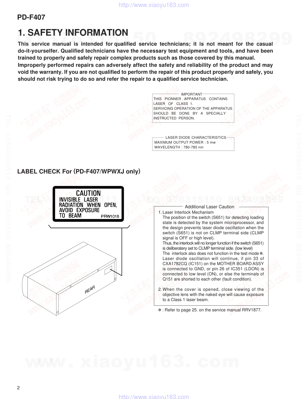
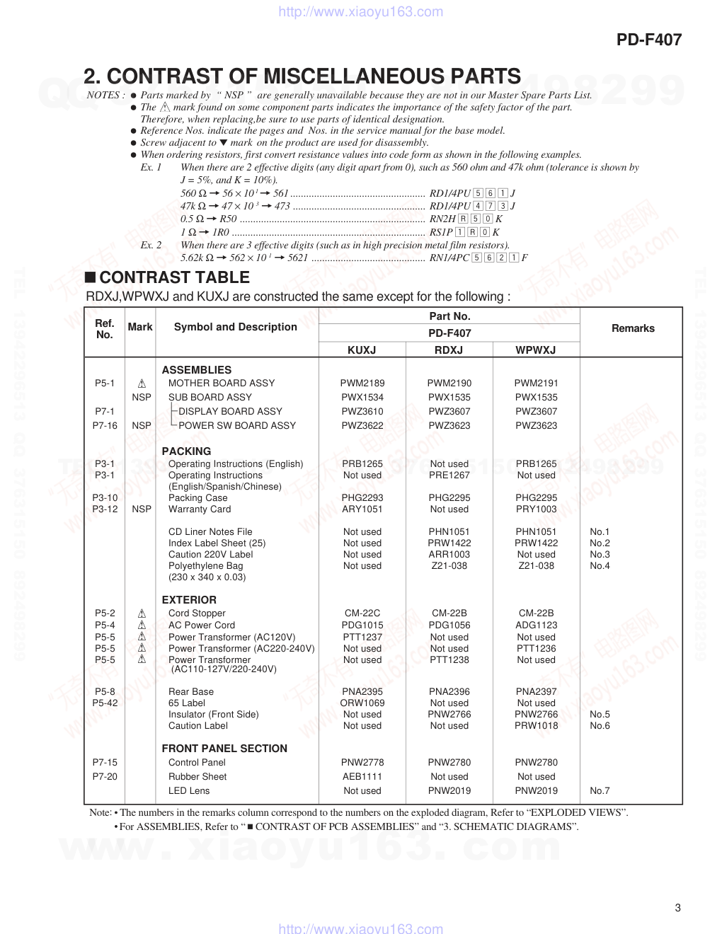
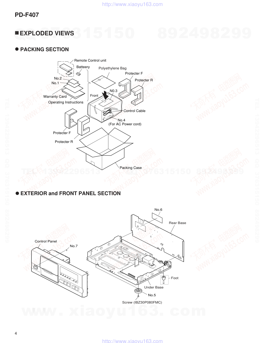
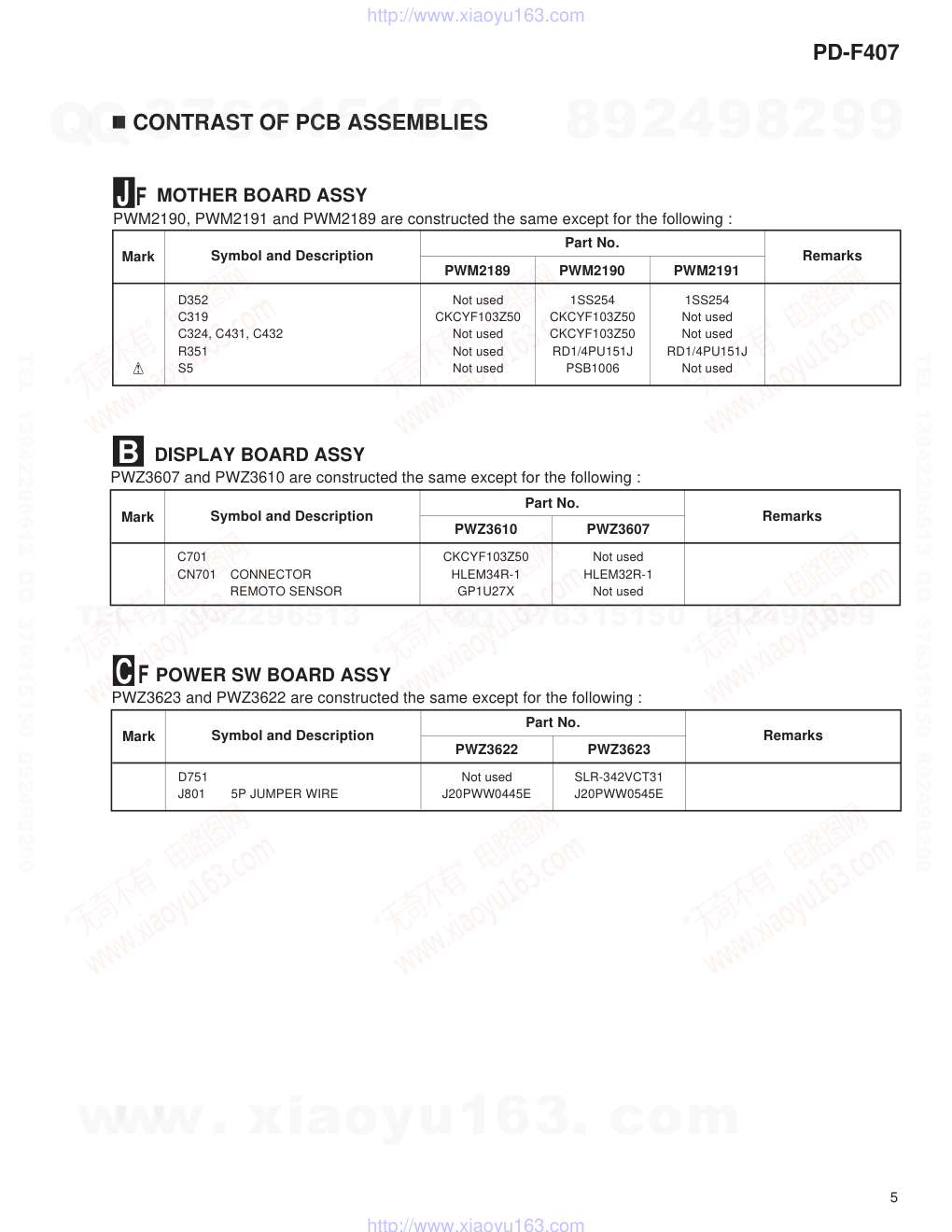
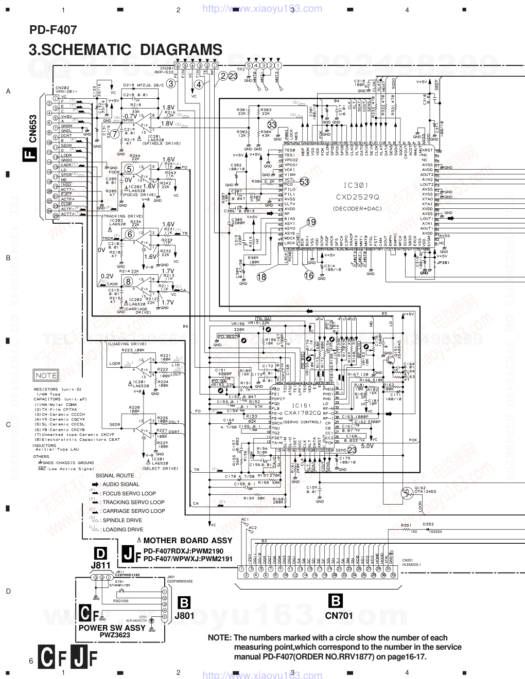
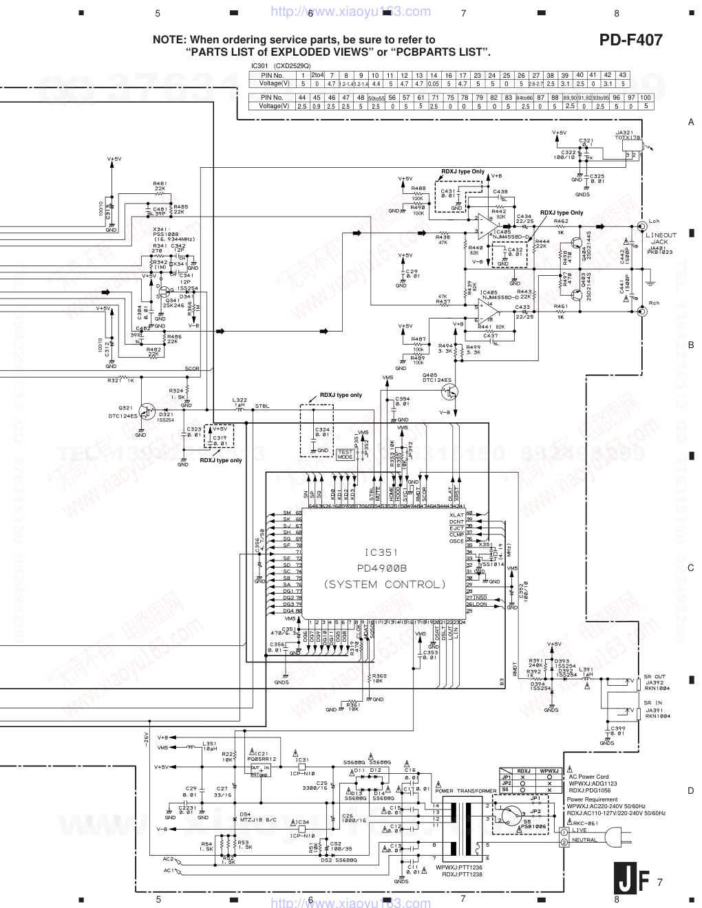
ORDER NO. PIONEER ELECTRONIC CORPORATION 4-1, Meguro 1-Chome, Meguro-ku, Tokyo 153-8654, Japan PIONEER ELECTRONICS SERVICE, INC. P.O. Box 1760, Long Beach, CA 90801-1760, U.S.A. PIONEER ELECTRONIC (EUROPE) N.V . Haven 1087, Keetberglaan 1, 9120 Melsele, Belgium PIONEER ELECTRONICS ASIACENTRE PTE. LTD. 501 Orchard Road, #10-00 Wheelock Place, Singapore 23880 C C C C C�PIONEER ELECTRONIC CORPORATION 1998 FILE-TYPE CD PLAYER RRV1952 PD-F407 T–ZZY APR. 1998 Printed in Japan Refer to the service manual RRV1877 for PD-F407/KUXJ. CONTENTS 1. SAFETY INFORMATION.................................... 2 2. CONTRAST OF MISCELLANEOUS PARTS ..... 3 3. SCHEMATIC DIAGRAMS .................................. 6 THIS MANUAL IS APPLICABLE TO THE FOLLOWING MODEL(S) AND TYPE(S). The voltage can be converted by the following method. Power Requirement Type Model PD-F407 RDXJ O AC110-127V/220-240V With the voltage selector WPWXJ O AC220-240V www. xiaoyu163. com QQ 376315150 9 9 2 8 9 4 2 9 8 TEL 13942296513 9 9 2 8 9 4 2 9 8 0 5 1 5 1 3 6 7 3 Q Q TEL 13942296513 QQ 376315150 892498299 TEL 13942296513 QQ 376315150 892498299 http://www.xiaoyu163.com PD-F407 2 1. SAFETY INFORMATION Additional Laser Caution 1. Laser Interlock Mechanism The position of the switch (S651) for detecting loading state is detected by the system microprocessor, and the design prevents laser diode oscillation when the switch (S651) is not on CLMP terminal side (CLMP signal is OFF or high level). Thus, the interlock will no longer function if the switch (S651) is deliberatery set to CLMP terminal side. (low level) The interlock also does not function in the test mode 8. Laser diode oscillation will continue, if pin 33 of CXA1782CQ (IC151) on the MOTHER BOARD ASSY is connected to GND, or pin 26 of IC351 (LDON) is connected to low level (ON), or else the terminals of Q151 are shorted to each other (fault condition). 2. When the cover is opened, close viewing of the objective lens with the naked eye will cause exposure to a Class 1 laser beam. 8 : Refer to page 25. on the service manual RRV1877. This service manual is intended for qualified service technicians; it is not meant for the casual do-it-yourselfer. Qualified technicians have the necessary test equipment and tools, and have been trained to properly and safely repair complex products such as those covered by this manual. Improperly performed repairs can adversely affect the safety and reliability of the product and may void the warranty. If you are not qualified to perform the repair of this product properly and safely, you should not risk trying to do so and refer the repair to a qualified service technician. LABEL CHECK For (PD-F407/WPWXJ only) REAR IMPORTANT THIS PIONNER APPARATUS CONTAINS LASER OF CLASS 1. SERVICING OPERATION OF THE APPARATUS SHOULD BE DONE BY A SPECIALLY INSTRUCTED PERSON. LASER DIODE CHARACTERISTICS MAXIMUM OUTPUT POWER : 5 mw WAVELENGTH : 780-785 nm www. xiaoyu163. com QQ 376315150 9 9 2 8 9 4 2 9 8 TEL 13942296513 9 9 2 8 9 4 2 9 8 0 5 1 5 1 3 6 7 3 Q Q TEL 13942296513 QQ 376315150 892498299 TEL 13942296513 QQ 376315150 892498299 http://www.xiaoyu163.com PD-F407 3 2. CONTRAST OF MISCELLANEOUS PARTS NOTES : ÷ Parts marked by “ NSP ” are generally unavailable because they are not in our Master Spare Parts List. ÷ The mark found on some component parts indicates the importance of the safety factor of the part. Therefore, when replacing,be sure to use parts of identical designation. ÷ Reference Nos. indicate the pages and Nos. in the service manual for the base model. ÷ Screw adjacent to ∞ mark on the product are used for disassembly. ÷ When ordering resistors, first convert resistance values into code form as shown in the following examples. Ex. 1 When there are 2 effective digits (any digit apart from 0), such as 560 ohm and 47k ohm (tolerance is shown by J = 5%, and K = 10%). 560 Ω = 56 × 10 1 = 561 ................................................... RD1/4PU 5 6 1 J 47k Ω = 47 × 10 3 = 473 .................................................. RD1/4PU 4 7 3 J 0.5 Ω = R50 ...................................................................... RN2H Â 5 0 K 1 Ω = 1R0 ......................................................................... RS1P 1 Â 0 K Ex. 2 When there are 3 effective digits (such as in high precision metal film resistors). 5.62k Ω = 562 × 10 1 = 5621 ........................................... RN1/4PC 5 6 2 1 F CONTRAST TABLE RDXJ,WPWXJ and KUXJ are constructed the same except for the following : Part No. Remarks KUXJ RDXJ WPWXJ Ref. No. Mark Symbol and Description PD-F407 ASSEMBLIES P5-1 MOTHER BOARD ASSY PWM2189 PWM2190 PWM2191 NSP SUB BOARD ASSY PWX1534 PWX1535 PWX1535 P7-1 DISPLAY BOARD ASSY PWZ3610 PWZ3607 PWZ3607 P7-16 NSP POWER SW BOARD ASSY PWZ3622 PWZ3623 PWZ3623 PACKING P3-1 Operating Instructions (English) PRB1265 Not used PRB1265 P3-1 Operating Instructions Not used PRE1267 Not used (English/Spanish/Chinese) P3-10 Packing Case PHG2293 PHG2295 PHG2295 P3-12 NSP Warranty Card ARY1051 Not used PRY1003 CD Liner Notes File Not used PHN1051 PHN1051 No.1 Index Label Sheet (25) Not used PRW1422 PRW1422 No.2 Caution 220V Label Not used ARR1003 Not used No.3 Polyethylene Bag Not used Z21-038 Z21-038 No.4 (230 x 340 x 0.03) EXTERIOR P5-2 Cord Stopper CM-22C CM-22B CM-22B P5-4 AC Power Cord PDG1015 PDG1056 ADG1123 P5-5 Power Transformer (AC120V) PTT1237 Not used Not used P5-5 Power Transformer (AC220-240V) Not used Not used PTT1236 P5-5 Power Transformer Not used PTT1238 Not used (AC110-127V/220-240V) P5-8 Rear Base PNA2395 PNA2396 PNA2397 P5-42 65 Label ORW1069 Not used Not used Insulator (Front Side) Not used PNW2766 PNW2766 No.5 Caution Label Not used Not used PRW1018 No.6 FRONT PANEL SECTION P7-15 Control Panel PNW2778 PNW2780 PNW2780 P7-20 Rubber Sheet AEB1111 Not used Not used LED Lens Not used PNW2019 PNW2019 No.7 Note: The numbers in the remarks column correspond to the numbers on the exploded diagram, Refer to “EXPLODED VIEWS”. For ASSEMBLIES, Refer to “ CONTRAST OF PCB ASSEMBLIES” and “3. SCHEMATIC DIAGRAMS”. www. xiaoyu163. com QQ 376315150 9 9 2 8 9 4 2 9 8 TEL 13942296513 9 9 2 8 9 4 2 9 8 0 5 1 5 1 3 6 7 3 Q Q TEL 13942296513 QQ 376315150 892498299 TEL 13942296513 QQ 376315150 892498299 http://www.xiaoyu163.com PD-F407 4 Packing Case No.2 No.1 Front Polyethylene Bag No.4 Protecter F Protecter F Protecter R Protecter R Operating Instructions Warranty Card Remote Control unit Batteery Control Cable N0.3 (For AC Power cord) EXTERIOR and FRONT PANEL SECTION EXPLODED VIEWS PACKING SECTION Rear Base Under Base Foot Screw (IBZ30P080FMC) No.7 Control Panel No.5 No.6 www. xiaoyu163. com QQ 376315150 9 9 2 8 9 4 2 9 8 TEL 13942296513 9 9 2 8 9 4 2 9 8 0 5 1 5 1 3 6 7 3 Q Q TEL 13942296513 QQ 376315150 892498299 TEL 13942296513 QQ 376315150 892498299 http://www.xiaoyu163.com PD-F407 5 CONTRAST OF PCB ASSEMBLIES DISPLAY BOARD ASSY PWZ3607 and PWZ3610 are constructed the same except for the following : D352 Not used 1SS254 1SS254 C319 CKCYF103Z50 CKCYF103Z50 Not used C324, C431, C432 Not used CKCYF103Z50 Not used R351 Not used RD1/4PU151J RD1/4PU151J S5 Not used PSB1006 Not used Mark Symbol and Description Part No. PWM2189 PWM2190 PWM2191 Remarks C701 CKCYF103Z50 Not used CN701 CONNECTOR HLEM34R-1 HLEM32R-1 REMOTO SENSOR GP1U27X Not used Mark Remarks Symbol and Description Part No. PWZ3610 PWZ3607 MOTHER BOARD ASSY PWM2190, PWM2191 and PWM2189 are constructed the same except for the following : J F B POWER SW BOARD ASSY PWZ3623 and PWZ3622 are constructed the same except for the following : D751 Not used SLR-342VCT31 J801 5P JUMPER WIRE J20PWW0445E J20PWW0545E Mark Remarks Symbol and Description Part No. PWZ3622 PWZ3623 C F www. xiaoyu163. com QQ 376315150 9 9 2 8 9 4 2 9 8 TEL 13942296513 9 9 2 8 9 4 2 9 8 0 5 1 5 1 3 6 7 3 Q Q TEL 13942296513 QQ 376315150 892498299 TEL 13942296513 QQ 376315150 892498299 http://www.xiaoyu163.com A B C D 1 2 3 4 1 2 3 4 PD-F407 6 3.SCHEMATIC DIAGRAMS NOTE: The numbers marked with a circle show the number of each measuring point,which correspond to the number in the service manual PD-F407(ORDER NO.RRV1877) on page16-17. J F C F MOTHER BOARD ASSY PD-F407RDXJ:PWM2190 PD-F407/WPWXJ:PWM2191 SIGNAL ROUTE : AUDIO SIGNAL : FOCUS SERVO LOOP : TRACKING SERVO LOOP : CARRIAGE SERVO LOOP : SPINDLE DRIVE : LOADING DRIVE 23 16 19 18 53 33 2 23 4 3 7 5 6 8 5.0V 1.7V 1.7V 0.2V 1.6V 1.6V 0V 1.6V 1.6V 0V 1.8V 1.8V -0.7V B CN701 F CN653 STBL J CN351 HLEM32S-1 150 1SS254 J801 POWER SW ASSY PWZ3623 5 D751 SLR-342VCT31 J811 J801 D20PWW0545E RSG1030 B D C F www. xiaoyu163. com QQ 376315150 9 9 2 8 9 4 2 9 8 TEL 13942296513 9 9 2 8 9 4 2 9 8 0 5 1 5 1 3 6 7 3 Q Q TEL 13942296513 QQ 376315150 892498299 TEL 13942296513 QQ 376315150 892498299 http://www.xiaoyu163.com A B C D 5 6 7 8 5 6 7 8 PD-F407 7 NOTE: When ordering service parts, be sure to refer to “PARTS LIST of EXPLODED VIEWS” or “PCBPARTS LIST”. J F PIN No. Voltage(V) 5 0 1 2to4 7 8 9 4.7 1.2-1.4 10 11 12 13 4.4 5 4.7 4.7 14 16 17 23 24 0.05 5 5 25 26 27 38 39 0 2.5 3.1 40 IC301 (CXD2529Q) 1.2-1.4 4.7 5 5 2.6-2.7 2.5 41 42 0 3.1 43 5 PIN No. Voltage(V) 2.5 0.9 44 45 46 47 48 2.5 2.5 50to55 56 57 61 2.5 0 5 5 71 75 78 79 82 2.5 0 5 83 84to86 87 88 89,90 5 5 2.5 91,92 5 0 0 2.5 0 0 93to95 96 2.5 5 97 0 100 5 AC Power Cord WPWXJ:ADG1123 RDXJ:PDG1056 Power Requirement WPWXJ:AC220-240V 50/60Hz RDXJ:AC110-127V/220-240V 50/60Hz WPWXJ:PTT1236 RDXJ:PTT1238 RDXJ WPWXJ JP1 JP2 S5 RDXJ type Only RDXJ type Only 1K 1K 82K 82K 82K 82K 47K 47K 100K 100K 100k 100k 100/10 100/10 1SS254 RDXJ type only RDXJ type only www. xiaoyu163. com QQ 376315150 9 9 2 8 9 4 2 9 8 TEL 13942296513 9 9 2 8 9 4 2 9 8 0 5 1 5 1 3 6 7 3 Q Q TEL 13942296513 QQ 376315150 892498299 TEL 13942296513 QQ 376315150 892498299 http://www.xiaoyu163.com
版权声明
1. 本站所有素材,仅限学习交流,仅展示部分内容,如需查看完整内容,请下载原文件。
2. 会员在本站下载的所有素材,只拥有使用权,著作权归原作者所有。
3. 所有素材,未经合法授权,请勿用于商业用途,会员不得以任何形式发布、传播、复制、转售该素材,否则一律封号处理。
4. 如果素材损害你的权益请联系客服QQ:77594475 处理。