先锋PIONEER M-10X音响电路图
 "先锋PIONEER M-10X音响电路图-0")
 "先锋PIONEER M-10X音响电路图-1")
 "先锋PIONEER M-10X音响电路图-2")
 "先锋PIONEER M-10X音响电路图-3")
 "先锋PIONEER M-10X音响电路图-4")
 "先锋PIONEER M-10X音响电路图-5")
 "先锋PIONEER M-10X音响电路图-6")
 "先锋PIONEER M-10X音响电路图-7")
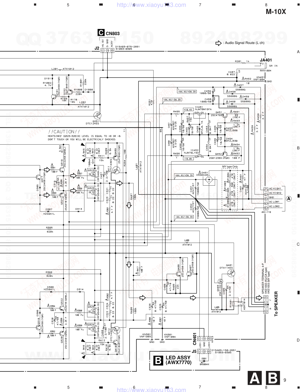 "先锋PIONEER M-10X音响电路图-8")
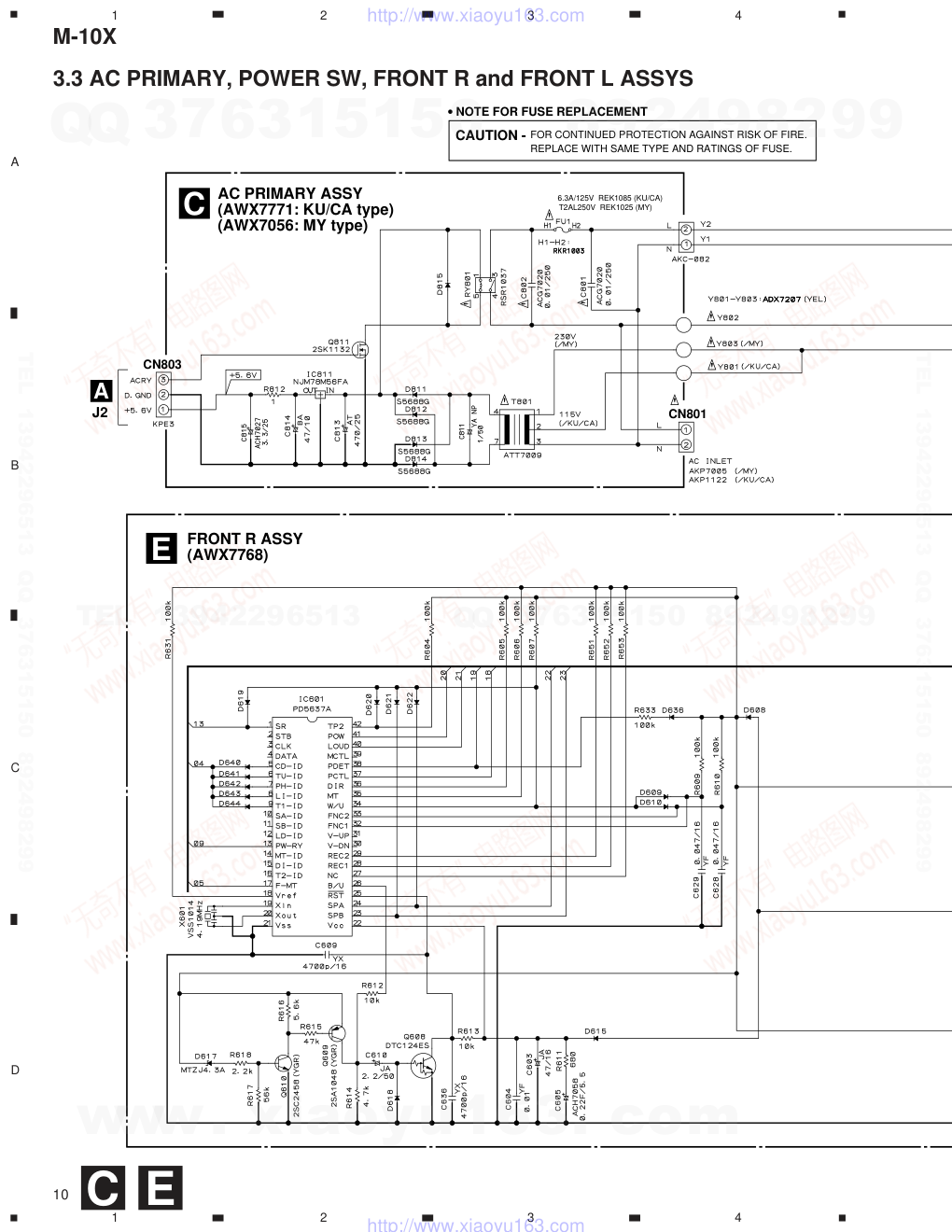 "先锋PIONEER M-10X音响电路图-9")
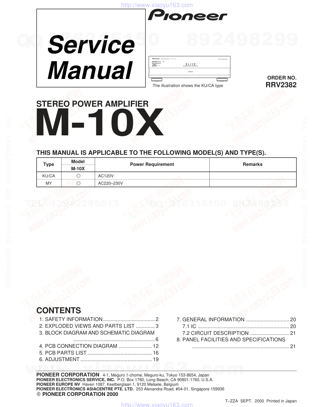
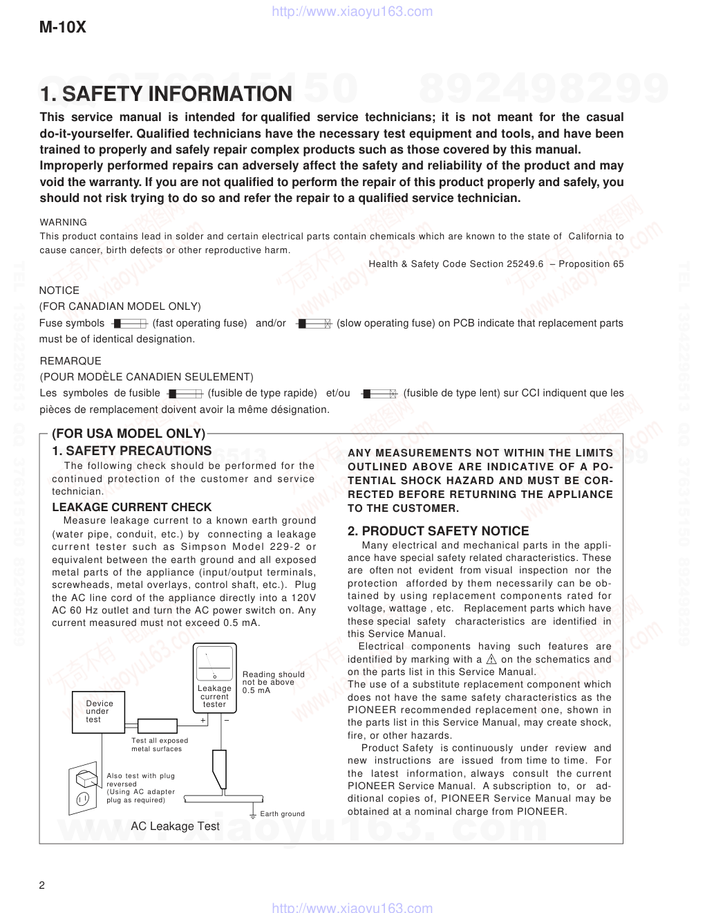
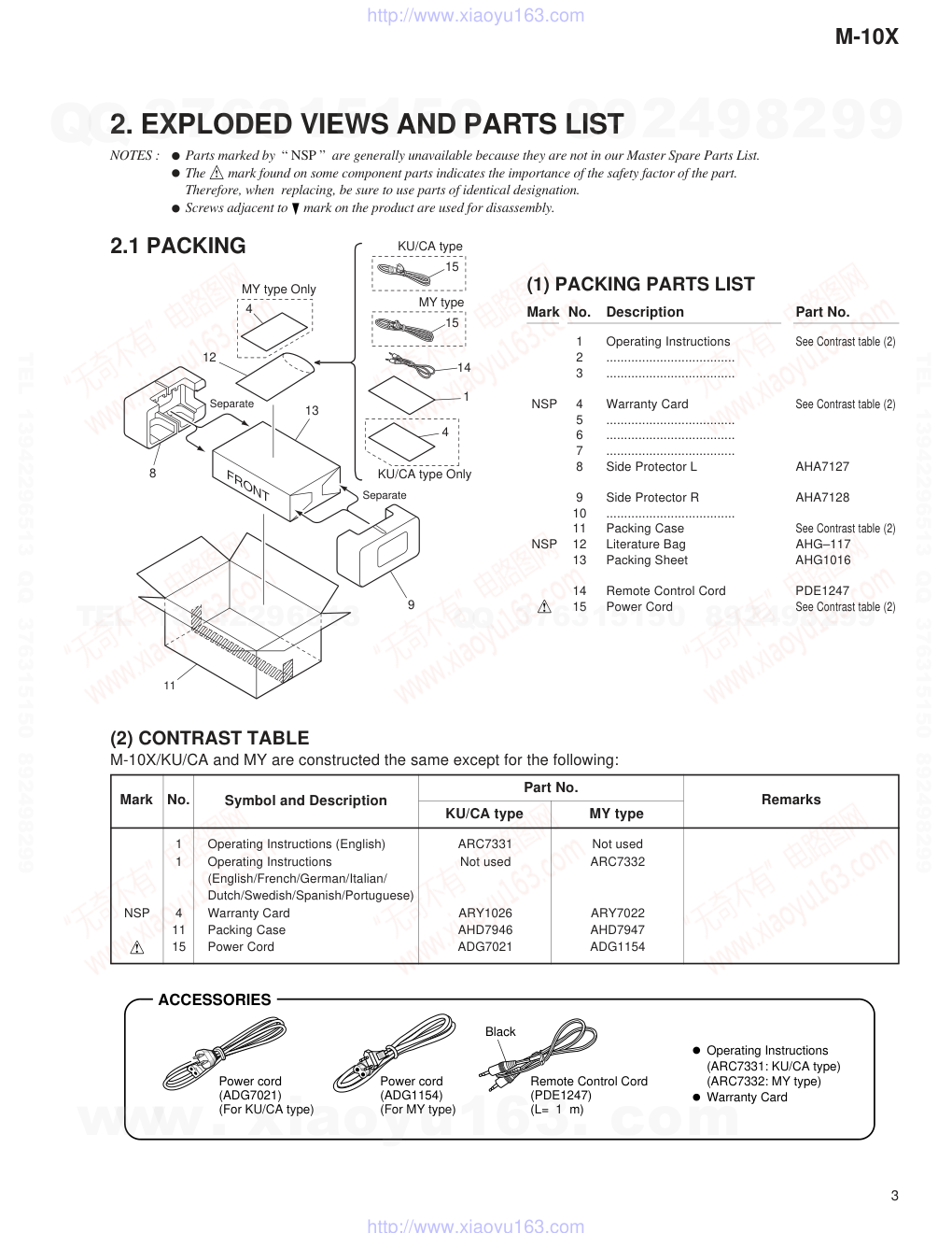
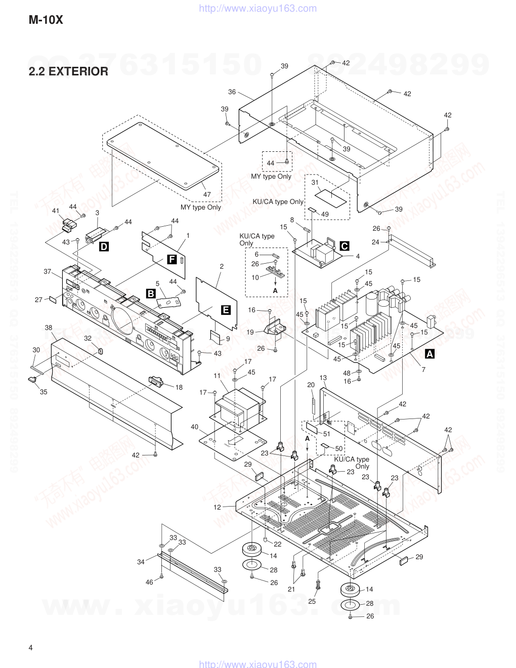
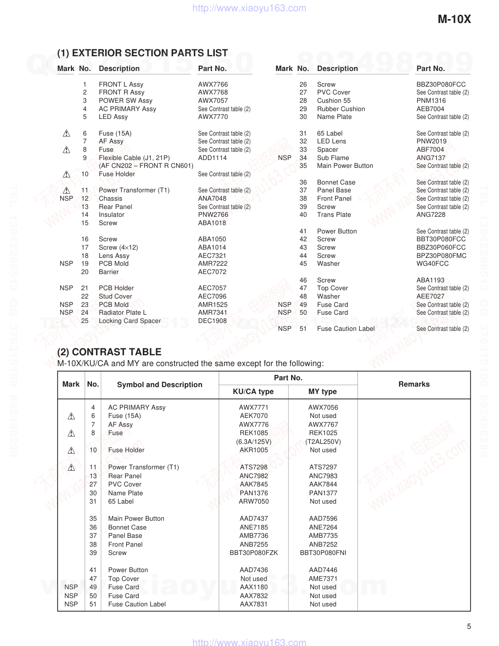
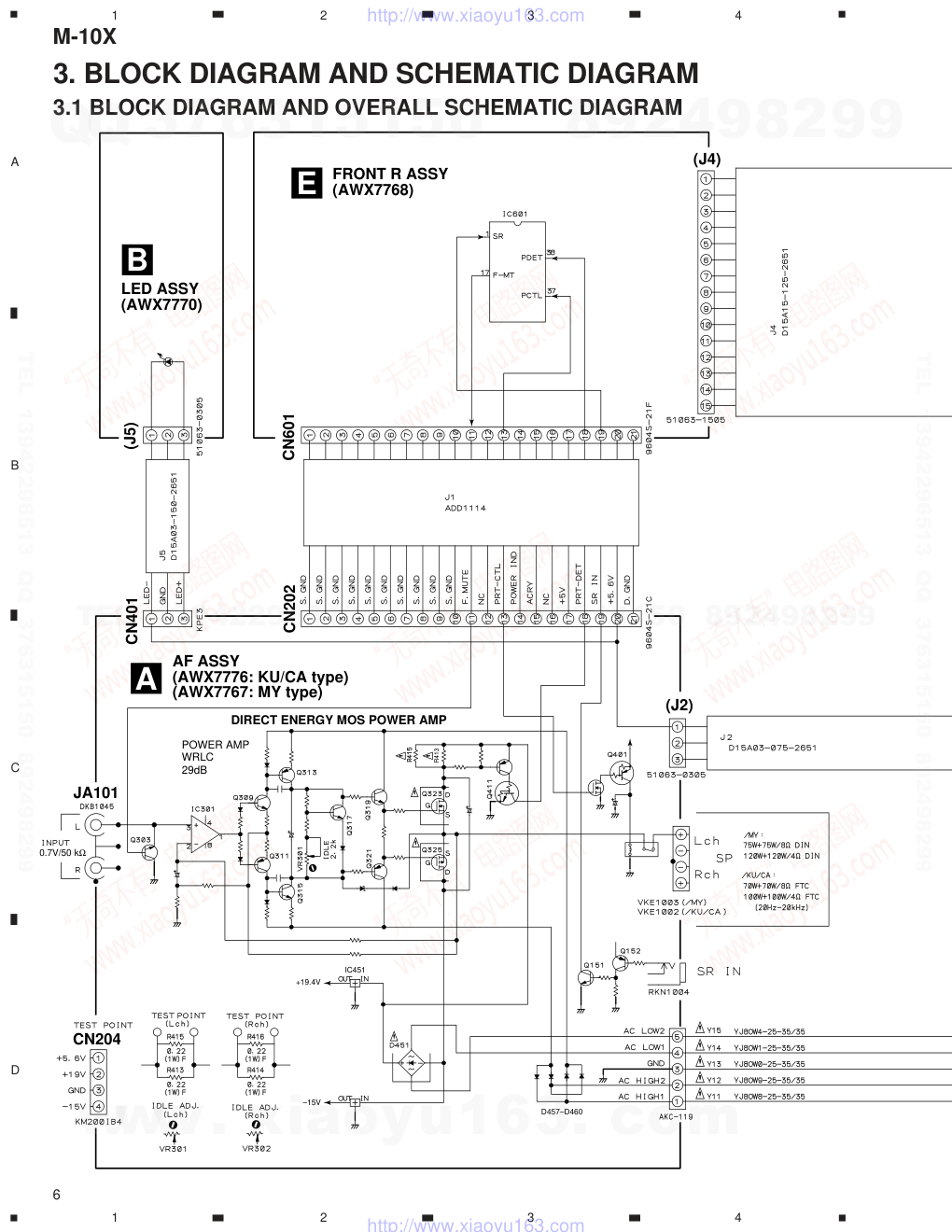
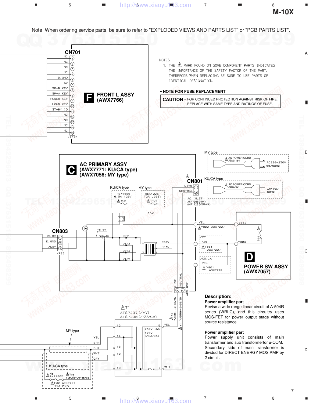
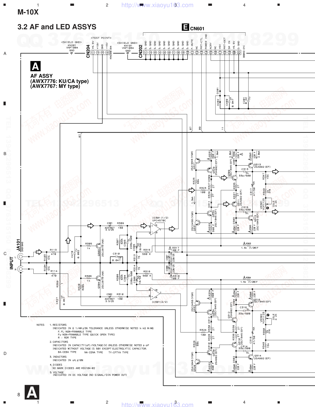
ORDER NO. PIONEER CORPORATION 4-1, Meguro 1-chome, Meguro-ku, Tokyo 153-8654, Japan PIONEER ELECTRONICS SERVICE, INC. P.O. Box 1760, Long Beach, CA 90801-1760, U.S.A. PIONEER EUROPE NV Haven 1087, Keetberglaan 1, 9120 Melsele, Belgium PIONEER ELECTRONICS ASIACENTRE PTE. LTD. 253 Alexandra Road, #04-01, Singapore 159936 PIONEER CORPORATION 2000 STEREO POWER AMPLIFIER RRV2382 T–ZZA SEPT. 2000 Printed in Japan M-10X 1. SAFETY INFORMATION.................................... 2 2. EXPLODED VIEWS AND PARTS LIST ............. 3 3. BLOCK DIAGRAM AND SCHEMATIC DIAGRAM ......................................................... 6 4. PCB CONNECTION DIAGRAM ....................... 12 5. PCB PARTS LIST ............................................. 16 6. ADJUSTMENT.................................................. 19 CONTENTS 7. GENERAL INFORMATION .............................. 20 7.1 IC ................................................................ 20 7.2 CIRCUIT DESCRIPTION ........................... 21 8. PANEL FACILITIES AND SPECIFICATIONS .................................................................... 21 KU/CA AC120V MY AC220–230V THIS MANUAL IS APPLICABLE TO THE FOLLOWING MODEL(S) AND TYPE(S). Remarks Power Requirement Type Model M-10X STEREO POWER AMPLIFIER STANDBY/ON STANDBY OFF ON POWER Î� v¿,?m REFERENCE STEREO POWER AMPLIFIER The illustration shows the KU/CA type www. xiaoyu163. com QQ 376315150 9 9 2 8 9 4 2 9 8 TEL 13942296513 9 9 2 8 9 4 2 9 8 0 5 1 5 1 3 6 7 3 Q Q TEL 13942296513 QQ 376315150 892498299 TEL 13942296513 QQ 376315150 892498299 http://www.xiaoyu163.com M-10X 2 1. SAFETY INFORMATION 1. SAFETY PRECAUTIONS The following check should be performed for the continued protection of the customer and service technician. ANY MEASUREMENTS NOT WITHIN THE LIMITS OUTLINED ABOVE ARE INDICATIVE OF A PO- TENTIAL SHOCK HAZARD AND MUST BE COR- RECTED BEFORE RETURNING THE APPLIANCE TO THE CUSTOMER. 2. PRODUCT SAFETY NOTICE Many electrical and mechanical parts in the appli- ance have special safety related characteristics. These are often not evident from visual inspection nor the protection afforded by them necessarily can be ob- tained by using replacement components rated for voltage, wattage , etc. Replacement parts which have these special safety characteristics are identified in this Service Manual. Electrical components having such features are identified by marking with a on the schematics and on the parts list in this Service Manual. The use of a substitute replacement component which does not have the same safety characteristics as the PIONEER recommended replacement one, shown in the parts list in this Service Manual, may create shock, fire, or other hazards. Product Safety is continuously under review and new instructions are issued from time to time. For the latest information, always consult the current PIONEER Service Manual. A subscription to, or ad- ditional copies of, PIONEER Service Manual may be obtained at a nominal charge from PIONEER. LEAKAGE CURRENT CHECK Measure leakage current to a known earth ground (water pipe, conduit, etc.) by connecting a leakage current tester such as Simpson Model 229-2 or equivalent between the earth ground and all exposed metal parts of the appliance (input/output terminals, screwheads, metal overlays, control shaft, etc.). Plug the AC line cord of the appliance directly into a 120V AC 60 Hz outlet and turn the AC power switch on. Any current measured must not exceed 0.5 mA. (FOR USA MODEL ONLY) Also test with plug reversed (Using AC adapter plug as required) Device under test Test all exposed metal surfaces Earth ground Leakage current tester Reading should not be above 0.5 mA AC Leakage Test REMARQUE (POUR MODÈLE CANADIEN SEULEMENT) Les symboles de fusible (fusible de type rapide) et/ou (fusible de type lent) sur CCI indiquent que les pièces de remplacement doivent avoir la même désignation. NOTICE (FOR CANADIAN MODEL ONLY) Fuse symbols (fast operating fuse) and/or (slow operating fuse) on PCB indicate that replacement parts must be of identical designation. This service manual is intended for qualified service technicians; it is not meant for the casual do-it-yourselfer. Qualified technicians have the necessary test equipment and tools, and have been trained to properly and safely repair complex products such as those covered by this manual. Improperly performed repairs can adversely affect the safety and reliability of the product and may void the warranty. If you are not qualified to perform the repair of this product properly and safely, you should not risk trying to do so and refer the repair to a qualified service technician. WARNING This product contains lead in solder and certain electrical parts contain chemicals which are known to the state of California to cause cancer, birth defects or other reproductive harm. Health & Safety Code Section 25249.6 – Proposition 65 www. xiaoyu163. com QQ 376315150 9 9 2 8 9 4 2 9 8 TEL 13942296513 9 9 2 8 9 4 2 9 8 0 5 1 5 1 3 6 7 3 Q Q TEL 13942296513 QQ 376315150 892498299 TEL 13942296513 QQ 376315150 892498299 http://www.xiaoyu163.com M-10X 3 FRONT 12 13 Separate KU/CA type Only MY type Only MY type Separate 8 11 9 14 15 15 1 4 4 KU/CA type 2. EXPLODED VIEWS AND PARTS LIST 2.1 PACKING (1) PACKING PARTS LIST 1 Operating Instructions See Contrast table (2) 2 .................................... 3 .................................... NSP 4 Warranty Card See Contrast table (2) 5 .................................... 6 .................................... 7 .................................... 8 Side Protector L AHA7127 9 Side Protector R AHA7128 10 .................................... 11 Packing Case See Contrast table (2) NSP 12 Literature Bag AHG–117 13 Packing Sheet AHG1016 14 Remote Control Cord PDE1247 15 Power Cord See Contrast table (2) NOTES : Parts marked by “ NSP ” are generally unavailable because they are not in our Master Spare Parts List. The mark found on some component parts indicates the importance of the safety factor of the part. Therefore, when replacing, be sure to use parts of identical designation. Screws adjacent to mark on the product are used for disassembly. Mark No. Description Part No. Mark KU/CA type MY type M-10X/KU/CA and MY are constructed the same except for the following: 1 Operating Instructions (English) ARC7331 Not used 1 Operating Instructions Not used ARC7332 (English/French/German/Italian/ Dutch/Swedish/Spanish/Portuguese) NSP 4 Warranty Card ARY1026 ARY7022 11 Packing Case AHD7946 AHD7947 15 Power Cord ADG7021 ADG1154 Part No. Remarks Symbol and Description No. (2) CONTRAST TABLE ACCESSORIES Power cord (ADG1154) (For MY type) Remote Control Cord (PDE1247) (L= 1 m) Operating Instructions (ARC7331: KU/CA type) (ARC7332: MY type) Warranty Card Black Power cord (ADG7021) (For KU/CA type) www. xiaoyu163. com QQ 376315150 9 9 2 8 9 4 2 9 8 TEL 13942296513 9 9 2 8 9 4 2 9 8 0 5 1 5 1 3 6 7 3 Q Q TEL 13942296513 QQ 376315150 892498299 TEL 13942296513 QQ 376315150 892498299 http://www.xiaoyu163.com M-10X 4 37 35 43 41 44 2 30 38 32 18 22 21 25 26 14 12 23 23 23 23 20 42 42 42 7 15 45 4 8 31 15 15 15 45 45 15 49 45 48 16 51 50 15 45 26 13 15 6 26 10 16 A A 19 42 11 17 17 45 17 43 9 3 44 44 44 5 1 24 46 34 33 33 33 40 27 29 29 28 26 14 28 39 39 39 42 42 42 39 44 47 MY type Only MY type Only KU/CA type Only KU/CA type Only KU/CA type Only 36 A B C D E F 26 2.2 EXTERIOR www. xiaoyu163. com QQ 376315150 9 9 2 8 9 4 2 9 8 TEL 13942296513 9 9 2 8 9 4 2 9 8 0 5 1 5 1 3 6 7 3 Q Q TEL 13942296513 QQ 376315150 892498299 TEL 13942296513 QQ 376315150 892498299 http://www.xiaoyu163.com M-10X 5 4 AC PRIMARY Assy AWX7771 AWX7056 6 Fuse (15A) AEK7070 Not used 7 AF Assy AWX7776 AWX7767 8 Fuse REK1085 REK1025 (6.3A/125V) (T2AL250V) 10 Fuse Holder AKR1005 Not used 11 Power Transformer (T1) ATS7298 ATS7297 13 Rear Panel ANC7982 ANC7983 27 PVC Cover AAK7845 AAK7844 30 Name Plate PAN1376 PAN1377 31 65 Label ARW7050 Not used 35 Main Power Button AAD7437 AAD7596 36 Bonnet Case ANE7185 ANE7264 37 Panel Base AMB7736 AMB7735 38 Front Panel ANB7255 ANB7252 39 Screw BBT30P080FZK BBT30P080FNI 41 Power Button AAD7436 AAD7446 47 Top Cover Not used AME7371 NSP 49 Fuse Card AAX1180 Not used NSP 50 Fuse Card AAX7832 Not used NSP 51 Fuse Caution Label AAX7831 Not used Mark KU/CA type MY type M-10X/KU/CA and MY are constructed the same except for the following: Part No. Remarks Symbol and Description No. (2) CONTRAST TABLE (1) EXTERIOR SECTION PARTS LIST 1 FRONT L Assy AWX7766 2 FRONT R Assy AWX7768 3 POWER SW Assy AWX7057 4 AC PRIMARY Assy See Contrast table (2) 5 LED Assy AWX7770 6 Fuse (15A) See Contrast table (2) 7 AF Assy See Contrast table (2) 8 Fuse See Contrast table (2) 9 Flexible Cable (J1, 21P) ADD1114 (AF CN202 – FRONT R CN601) 10 Fuse Holder See Contrast table (2) 11 Power Transformer (T1) See Contrast table (2) NSP 12 Chassis ANA7048 13 Rear Panel See Contrast table (2) 14 Insulator PNW2766 15 Screw ABA1018 16 Screw ABA1050 17 Screw (4×12) ABA1014 18 Lens Assy AEC7321 NSP 19 PCB Mold AMR7222 20 Barrier AEC7072 NSP 21 PCB Holder AEC7057 22 Stud Cover AEC7096 NSP 23 PCB Mold AMR1525 NSP 24 Radiator Plate L AMR7341 25 Locking Card Spacer DEC1908 Mark No. Description Part No. 26 Screw BBZ30P080FCC 27 PVC Cover See Contrast table (2) 28 Cushion 55 PNM1316 29 Rubber Cushion AEB7004 30 Name Plate See Contrast table (2) 31 65 Label See Contrast table (2) 32 LED Lens PNW2019 33 Spacer ABF7004 NSP 34 Sub Flame ANG7137 35 Main Power Button See Contrast table (2) 36 Bonnet Case See Contrast table (2) 37 Panel Base See Contrast table (2) 38 Front Panel See Contrast table (2) 39 Screw See Contrast table (2) 40 Trans Plate ANG7228 41 Power Button See Contrast table (2) 42 Screw BBT30P080FCC 43 Screw BBZ30P060FCC 44 Screw BPZ30P080FMC 45 Washer WG40FCC 46 Screw ABA1193 47 Top Cover See Contrast table (2) 48 Washer AEE7027 NSP 49 Fuse Card See Contrast table (2) NSP 50 Fuse Card See Contrast table (2) NSP 51 Fuse Caution Label See Contrast table (2) Mark No. Description Part No. www. xiaoyu163. com QQ 376315150 9 9 2 8 9 4 2 9 8 TEL 13942296513 9 9 2 8 9 4 2 9 8 0 5 1 5 1 3 6 7 3 Q Q TEL 13942296513 QQ 376315150 892498299 TEL 13942296513 QQ 376315150 892498299 http://www.xiaoyu163.com M-10X 6 A B C D 1 2 3 4 1 2 3 4 3. BLOCK DIAGRAM AND SCHEMATIC DIAGRAM D457–D460 IC451 +19.4V –15V R413 A B E LED ASSY (AWX7770) (J5) FRONT R ASSY (AWX7768) AF ASSY (AWX7776: KU/CA type) (AWX7767: MY type) CN601 (J4) (J2) DIRECT ENERGY MOS POWER AMP POWER AMP WRLC 29dB CN204 JA101 CN202 CN401 0.7V/50 kΩ 3.1 BLOCK DIAGRAM AND OVERALL SCHEMATIC DIAGRAM www. xiaoyu163. com QQ 376315150 9 9 2 8 9 4 2 9 8 TEL 13942296513 9 9 2 8 9 4 2 9 8 0 5 1 5 1 3 6 7 3 Q Q TEL 13942296513 QQ 376315150 892498299 TEL 13942296513 QQ 376315150 892498299 http://www.xiaoyu163.com M-10X 7 A B C D 5 6 7 8 5 6 7 8 • NOTE FOR FUSE REPLACEMENT FOR CONTINUED PROTECTION AGAINST RISK OF FIRE. REPLACE WITH SAME TYPE AND RATINGS OF FUSE. CAUTION - AC POWER CORD ADG7021 AC POWER CORD ADG1154 250V C D F FRONT L ASSY (AWX7766) POWER SW ASSY (AWX7057) AC PRIMARY ASSY (AWX7771: KU/CA type) (AWX7056: MY type) CN701 CN803 CN801 KU/CA type KU/CA type KU/CA type MY type MY type MY type Description: Power amplifier part Revise a wide range linear circuit of A-504R series (WRLC), and this circuitry uses MOS-FET for power output stage without source resistance. Power amplifier part Power supply unit consists of main transformer and sub transformerfor u-COM. Secondary side of main transformer is divided for DIRECT ENERGY MOS AMP by 2 circuit. Note: When ordering service parts, be sure to refer to "EXPLODED VIEWS AND PARTS LIST" or "PCB PARTS LIST". www. xiaoyu163. com QQ 376315150 9 9 2 8 9 4 2 9 8 TEL 13942296513 9 9 2 8 9 4 2 9 8 0 5 1 5 1 3 6 7 3 Q Q TEL 13942296513 QQ 376315150 892498299 TEL 13942296513 QQ 376315150 892498299 http://www.xiaoyu163.com M-10X 8 A B C D 1 2 3 4 1 2 3 4 JA101 CN202 CN601 CN204 INPUT 51k 820k 820k 51k A AF ASSY (AWX7776: KU/CA type) (AWX7767: MY type) E 3.2 AF and LED ASSYS A www. xiaoyu163. com QQ 376315150 9 9 2 8 9 4 2 9 8 TEL 13942296513 9 9 2 8 9 4 2 9 8 0 5 1 5 1 3 6 7 3 Q Q TEL 13942296513 QQ 376315150 892498299 TEL 13942296513 QQ 376315150 892498299 http://www.xiaoyu163.com M-10X 9 A B C D 5 6 7 8 5 6 7 8 CN401 J2 CN803 JA401 J5 A To SPEAKER SPEAKER TERMINAL 4-P VKE1002 (KU/CA type) VKE1003 (MY type) MY type Only B LED ASSY (AWX7770) C : Audio Signal Route (L ch) B A www. xiaoyu163. com QQ 376315150 9 9 2 8 9 4 2 9 8 TEL 13942296513 9 9 2 8 9 4 2 9 8 0 5 1 5 1 3 6 7 3 Q Q TEL 13942296513 QQ 376315150 892498299 TEL 13942296513 QQ 376315150 892498299 http://www.xiaoyu163.com M-10X 10 A B C D 1 2 3 4 1 2 3 4 CN803 CN801 C E FRONT R ASSY (AWX7768) AC PRIMARY ASSY (AWX7771: KU/CA type) (AWX7056: MY type) J2 A 6.3A/125V REK1085 (KU/CA) T2AL250V REK1025 (MY) • NOTE FOR FUSE REPLACEMENT FOR CONTINUED PROTECTION AGAINST RISK OF FIRE. REPLACE WITH SAME TYPE AND RATINGS OF FUSE. CAUTION - 3.3 AC PRIMARY, POWER SW, FRONT R and FRONT L ASSYS E C www. xiaoyu163. com QQ 376315150 9 9 2 8 9 4 2 9 8 TEL 13942296513 9 9 2 8 9 4 2 9 8 0 5 1 5 1 3 6 7 3 Q Q TEL 13942296513 QQ 376315150 892498299 TEL 13942296513 QQ 376315150 892498299 http://www.xiaoyu163.com M-10X 11 A B C D 5 6 7 8 5 6 7 8 CN601 CN701 J4 KU/CA type MY type A S901: POWER SW 250V D F FRONT L ASSY (AWX7766) POWER SW ASSY (AWX7057) CN202 A • NOTE FOR FUSE REPLACEMENT FOR CONTINUED PROTECTION AGAINST RISK OF FIRE. REPLACE WITH SAME TYPE AND RATINGS OF FUSE. CAUTION - F E D www. xiaoyu163. com QQ 376315150 9 9 2 8 9 4 2 9 8 TEL 13942296513 9 9 2 8 9 4 2 9 8 0 5 1 5 1 3 6 7 3 Q Q TEL 13942296513 QQ 376315150 892498299 TEL 13942296513 QQ 376315150 892498299 http://www.xiaoyu163.com M-10X 12 A B C D 1 2 3 4 1 2 3 4 NOTE FOR PCB DIAGRAMS: 1. Part numbers in PCB diagrams match those in the schematic diagrams. 2. A comparison between the main parts of PCB and schematic diagrams is shown below. Symbol in PCB Diagrams Symbol in Schematic Diagrams Part Name Transistor Transistor with resistor Field effect transistor B C E B C E B C E D G S B C E B C E B C E D G S D G S 3. The parts mounted on this PCB include all necessary parts for several destination. For further information for respective destinations, be sure to check with the schematic diagram. 4. Viewpoint of PCB diagrams Resistor array 3-terminal regulator Capacitor Connector P. C. Board Chip Part SIDE B SIDE A (ANP7377-A) A B LED ASSY AF ASSY Rear CN803 To POWER TRANSFORMER T1 C 4. PCB CONNECTION DIAGRAM B A 4.1 AF and LED ASSYS SIDE A www. xiaoyu163. com QQ 376315150 9 9 2 8 9 4 2 9 8 TEL 13942296513 9 9 2 8 9 4 2 9 8 0 5 1 5 1 3 6 7 3 Q Q TEL 13942296513 QQ 376315150 892498299 TEL 13942296513 QQ 376315150 892498299 http://www.xiaoyu163.com M-10X 13 A B C D 5 6 7 8 5 6 7 8 Q401 Q406 Q413 Q414 Q451 Q452 Q409 Q411 Q323 Q319 Q322 Q412 Q410 Q407 Q408 Q324 IC451 IC151 IC452 IC101 Q313 VR301 VR302 Q318 Q301 Q304 Q251 Q309 Q312 Q325 Q334 IC301 IC251 (ANP7376-A) Q101 Q104 Q151 Q153 CN601 E A www. xiaoyu163. com QQ 376315150 9 9 2 8 9 4 2 9 8 TEL 13942296513 9 9 2 8 9 4 2 9 8 0 5 1 5 1 3 6 7 3 Q Q TEL 13942296513 QQ 376315150 892498299 TEL 13942296513 QQ 376315150 892498299 http://www.xiaoyu163.com M-10X 14 A B C D 1 2 3 4 1 2 3 4 (ANP7376-A) F FRONT L ASSY A KU/CA type T1 POWER TRANSFORMER MY type Q705 VR751 VR752 Q704 Q701 Q702 Q707 Q706 Q703 IC751 Q751 Q752 Rear 4.2 AC PRIMARY, POWER SW, FRONT R and FRONT L ASSYS SIDE A F www. xiaoyu163. com QQ 376315150 9 9 2 8 9 4 2 9 8 TEL 13942296513 9 9 2 8 9 4 2 9 8 0 5 1 5 1 3 6 7 3 Q Q TEL 13942296513 QQ 376315150 892498299 TEL 13942296513 QQ 376315150 892498299 http://www.xiaoyu163.com M-10X 15 A B C D 5 6 7 8 5 6 7 8 (ANP7377-A) (ANP7377-A) (ANP7377-A) D POWER SW ASSY C AC PRIMARY ASSY E FRONT R ASSY CN202 A J2 A KU/CA type MY type LIVE NEUTRAL Q616 Q606 Q610 Q617 IC603 Q608 Q609 Q605 Q604 IC601 Q603 Q811 IC811 Q602 Q601 Q612 Q613 Q614 Q611 Q615 Q607 VR601 IC602 Q618 SIDE A E D C www. xiaoyu163. com QQ 376315150 9 9 2 8 9 4 2 9 8 TEL 13942296513 9 9 2 8 9 4 2 9 8 0 5 1 5 1 3 6 7 3 Q Q TEL 13942296513 QQ 376315150 892498299 TEL 13942296513 QQ 376315150 892498299 http://www.xiaoyu163.com M-10X 16 NSP CONTROL ASSY AWG7025 AWG7024 POWER SW ASSY AWX7057 AWX7057 FRONT R ASSY AWX7768 AWX7768 LED ASSY AWX7770 AWX7770 AC PRIMARY ASSY AWX7771 AWX7056 NSP AF COMPLEX ASSY AWK7679 AWK7678 FRONT L ASSY AWX7766 AWX7766 AF ASSY AWX7776 AWX7767 R1003 Not used RS3LMF391J R1004–R1006 Not used RS3LMF471J Speaker Terminal 4-P VKE1002 VKE1003 5. PCB PARTS LIST NOTES : ÷ Parts marked by “ NSP ” are generally unavailable because they are not in our Master Spare Parts List. ÷ The mark found on some component parts indicates the importance of the safety factor of the part. Therefore, when replacing, be sure to use parts of identical designation. ÷ When ordering resistors, first convert resistance values into code form as shown in the following examples. Ex. 1 When there are 2 effective digits (any digit apart from 0), such as 560 ohm and 47k ohm (tolerance is shown by J = 5%, and K = 10%). 560 Ω = 56 × 10 1 = 561 ................................................... RD1/4PU 5 6 1 J 47k Ω = 47 × 10 3 = 473 .................................................. RD1/4PU 4 7 3 J 0.5 Ω = R50 ...................................................................... RN2H  5 0 K 1 Ω = 1R0 ......................................................................... RS1P 1  0 K Ex. 2 When there are 3 effective digits (such as in high precision metal film resistors). 5.62k Ω = 562 × 10 1 = 5621 ........................................... RN1/4PC 5 6 2 1 F LIST OF WHOLE PCB ASSEMBLIES CONTRAST OF PCB ASSEMBLIES AC PRIMARY Assy AWX7771 and AWX7056 are constructed the same except for the following: CN801 AKP1122 AKP7005 Y801 ADX7207 Not used Y803 Not used ADX7207 Mark Remarks Symbol and Description Part No. AWX7771 AWX7056 AF Assy AWX7776 and AWX7767 are constructed the same except for the following: Mark Remarks Symbol and Description Part No. AWX7776 AWX7767 A Mark Remarks Symbol and Description Part No. KU/CA type MY type C www. xiaoyu163. com QQ 376315150 9 9 2 8 9 4 2 9 8 TEL 13942296513 9 9 2 8 9 4 2 9 8 0 5 1 5 1 3 6 7 3 Q Q TEL 13942296513 QQ 376315150 892498299 TEL 13942296513 QQ 376315150 892498299 http://www.xiaoyu163.com M-10X 17 PCB PARTS LIST FOR KU/CA TYPE POWER SW ASSY SWITCHES AND RELAYS S901 ASG1035 CAPACITORS C901 (3300pF/250V) ACG7017 FRONT R ASSY SEMICONDUCTORS IC601 PD5637A Q609 2SA1048 Q610 2SC2458 Q612 DTA124ES Q608 DTC124ES D608–D610, D615, D618–D622 HSS104–02 D636, D640–D644 HSS104–02 D617 MTZJ4.3A COILS AND FILTERS L601, L602, L608 LAU221J CAPACITORS C605 ACH7058 C610 CEJA2R2M50 C603 CEJA470M16 C604 CKCYF103Z50 C613, C620, C626 CKPUYF103Z25 C628, C629 CKPUYF473Z16 C609, C636 CKPUYX472M16 RESISTORS All Resistors RD1/4PU J OTHERS CABLE HOLDER (15P) 51063–1505 CN601 21P FFC CONNECTOR 9604S–21F J4 JUMPER WIRE D15A15–125–2651 X601 (4.19MHz) VSS1014 LED ASSY SEMICONDUCTORS D551 BR5064X OTHERS CABLE HOLDER (3P) 51063–0305 J5 JUMPER WIRE D15A03–150–2651 Mark No. Description Part No. AC PRIMARY ASSY SEMICONDUCTORS IC811 NJM78M56FA Q811 2SK1132 D815 HSS104–02 D811–D814 S5688G TRANSFORMERS T801 ATT7009 SWITCHES AND RELAYS RY801 RSR1037 CAPACITORS C801, C802 (10000pF/250V) ACG7020 C815 (3.3µF/25V) ACH7027 C813 CEAT471M25 C814 CEBA470M10 C811 CEYANP1R0M50 RESISTORS All Resistors RD1/4PU J OTHERS Y801, Y802 BOARD–IN READ WIRE ADX7207 CN801 AC INLET (1P) AKP1122 CN803 CONNECTOR (3P) KPE3 H1, H2 FUSE HOLDER RKR1003 FRONT L ASSY SEMICONDUCTORS Q702 2SC2458 Q701 DTC124ES D711 HSS104–02 D701 SLR–343VC (NPQ) SWITCHES AND RELAYS S701 VSG1009 CAPACITORS C711 CKPUYF473Z16 RESISTORS All Resistors RD1/4PU J OTHERS CN701 CONNECTOR (15P) KPE15 Mark No. Description Part No. B C E D F www. xiaoyu163. com QQ 376315150 9 9 2 8 9 4 2 9 8 TEL 13942296513 9 9 2 8 9 4 2 9 8 0 5 1 5 1 3 6 7 3 Q Q TEL 13942296513 QQ 376315150 892498299 TEL 13942296513 QQ 376315150 892498299 http://www.xiaoyu163.com M-10X 18 AF ASSY SEMICONDUCTORS IC451 NJM78M15FA IC452 NJM79L15A IC301 UPC4570C Q152, Q327, Q328, Q409, Q410 2SA1048 Q321, Q322 2SA970 Q311–Q314, Q329, Q330 2SA992 Q452 2SB1238X Q309, Q310, Q315, Q316 2SC1845 Q333, Q334 2SC1845 Q319, Q320 2SC2240 Q151, Q317, Q318, Q331, Q332 2SC2458 Q407, Q408 2SC2458 Q303, Q304 2SC2878 Q451 2SC4793 Q403 2SK1132 Q401 DTA114ES Q251 DTC124ES Q411, Q412 DTC143ES Q323, Q324 IRF540A Q325, Q326 IRF9540A D451 D5SBA20 D1000, D151, D201, D202 HSS104–02 D301–D306, D309–D314 HSS104–02 D307, D308 HZS9A1L D454 MTZJ33B D453 MTZJ36B D455 MTZJ4.7A D457–D460 S5688G COILS AND FILTERS L201, L202, L401, L405, L406 ATX1012 SWITCHES AND RELAYS RY401 ASR7014 CAPACITORS C461 (1µF/100V) ACH1237 C301, C302, C457, C458 (3.3µF/25V) ACH7027 C451, C452 (15000µ/50V) ACH7157 C303, C304 CCCSL221K2H C313–C316 CCCSL330K2H C408 CEANP470M10 C465, C466 CEAT100M50 C467, C468 CEAT2R2M2A C405 CEBA2R2M50 C325, C326 CEBAR47M50 C305, C306, C455, C456, C463 CENA100M50 C459, C460 CENA102M50 C317–C320 CENA470M50 C201, C321–C324 CFTYA224J50 C470 CFTYA823J50 C407 CKCYF223Z50 C310, C327, C409, C453, C454 CKCYF473Z50 C307, C308 (220µF/25V) PCH1128 RESISTORS R363, R364 RD1/2PMF152J R458, R459 RD1/4LMF2R2J R317, R318, R351–R354, R417 RD1/4MUF101J R452 RD1/4MUF101J R339–R346 RD1/4MUF221J R331–R334 RD1/4MUF391J R367, R368 RD1/4PMF100J R355, R356 RD1/4PMF222J R461 RD1/4PMF470J R361, R362 RD1/4PMF4R7J R462 RD1/4PU100J R315, R316 RDR1/4PM561J R357–R360 RFA1/4PS101J R349, R350 RN1/4PC2001F R451 RS1LMF330J R413–R416 RS1LMFR22J R453 RS2LMF122J R454 RS2LMF182J VR301, VR302 (2.2 kΩ) VCP1123 Other Resistors RD1/4PU J OTHERS CABLE HOLDER (3P) 51063–0305 CN202 21P FFC CONNECTOR 9604S–21C SCREW ABA–298 SCREW (STEEL) ABA1007 SCREW ABA1052 HEAT SINK B ANH1021 HEAT SINK ANH1150 J2 JUMPER WIRE D15A03–075–2651 JA101 PIN JACK (2P) DKB1045 CN204 4P PLUG KM200IB4 CN401 CONNECTOR (3P) KPE3 JA401 JACK RKN1004 PCB BINDER VEF1040 SPEAKER TERMINAL 4–P VKE1002 KN101, KN201, KN301, KN302, KN451 VNF1084 EARTH METAL FITTING Mark No. Description Part No. Mark No. Description Part No. A www. xiaoyu163. com QQ 376315150 9 9 2 8 9 4 2 9 8 TEL 13942296513 9 9 2 8 9 4 2 9 8 0 5 1 5 1 3 6 7 3 Q Q TEL 13942296513 QQ 376315150 892498299 TEL 13942296513 QQ 376315150 892498299 http://www.xiaoyu163.com M-10X 19 6. ADJUSTMENT 6.1 IDLE CURRENT ADJUSTMENT CAUTION : Heatsinks’ (Q323–Q326) DC level is equal to +B or –B. Don’t touch them or you will be electricary chocked. 1. Connect the measuring instrument as Fig.6–1. (R415 or R416) 2. Set VR301 and VR302 to minimum. 3. Set the POWER switch to ON. 4. Adjust VR301 (VR302) so that the voltage between both sides of R415 (R416) becomes 16mV±1mV. (Within 10 seconds from when the relay is turned ON) 5. Ages for 7 minutes. 6. Adjust VR301 (VR302) so that the voltage between both sides of R415 (R416) becomes 11mV±1mV. Fig. 6–1 Adjustment Method VR301 VR302 R413 R414 R415 R416 Heat Sink CN204 AF ASSY DC Voltmeter DC Voltmeter SIDE A Heat Sink Heat Sink Heat Sink R417 W212 W150 www. xiaoyu163. com QQ 376315150 9 9 2 8 9 4 2 9 8 TEL 13942296513 9 9 2 8 9 4 2 9 8 0 5 1 5 1 3 6 7 3 Q Q TEL 13942296513 QQ 376315150 892498299 TEL 13942296513 QQ 376315150 892498299 http://www.xiaoyu163.com M-10X 20 • The information shown in the list is basic information and may not correspond exactly to that shown in the schematic diagrams. 7. GENERAL INFORMATION PD5604A ( IC601: FRONT R ASSY) Remote Control Amp Microcomputer 7.1 IC Pin Function 1 2 3 4 5 6 7 8 9 10 11 12 13 14 15 16 17 18 19 20 21 22 23 24 25 26 27 28 29 30 31 32 33 34 35 36 37 38 39 40 41 42 SR STB CLK DATA CD-IND TU-IND PH-IND LI-IND T1-IND SPA-IND SPB-IND LOU-IND POW-IND MUT-IND DIR-IND T2-IND VREF XIN XOUT VSS F-MUTE P53 P17/SRDY P16/CLK P15/SOUT P14/SIN P13/T1 P12/T0 P11 P10 P27/IN7 P26/IN6 P25/IN5 P24/IN4 P23/IN3 P22/IN2 P21/IN1 P20/IN0 VREF XIN XOUT VSS T2 POWER LOUD M-CTRL P-DET P-CTRL DIRECT MUTE WAKE UP FUNC2 FUNC1 V-UP V-DOWN RSEL2 RSEL1 NC VCC P52 P07 P06 P05 P04 P03 P02 P01 P00 P43 P42 P41 P40 P33/CNTR1 P32/CNTR0 P31/INT1 P30/INT0 RESET P51/XCOUT P50/XCIN VCC BACK UP RST SPA SPB Pin Assignment (Top view) No. Pin Name I/O Description 1 P53 I Remote control signal input pin. 2 P17/SRDY O TC9163N STB 3 P16/CLK O TC9163N CLOCK 4 P15/SOUT O TC9163N DATA 5 P14/SIN O CD INDICATOR 6 P13/T1 O TUNER INDICATOR 7 P12/T0 O PHONO INDICATOR 8 P11 O LINE INDICATOR 9 P10 O TAPE1 INDICATOR 10 P27/IN7 O SPEAKER-A INDICATOR 11 P26/IN6 O SPEAKER-B INDICATOR 12 P25/IN5 O LOUDNESS INDICATOR 13 P24/IN4 O POWER (STAND-BY) INDICATOR 14 P23/IN3 O MUTE INDICATOR MUTE ON : Repeats H and L every 1 second. 15 P22/IN2 O DIRECT INDICATOR 16 P21/IN1 O TAPE2 INDICATOR 17 P20/IN0 O FUNCTION switch MUTE. 18 VREF I Pulls up to 5V. 19 XIN I 4.19MHz 20 XOUT O Ceramic vibrating and connecting terminal. 21 VSS –– Digatal GND. 22 VCC –– Power supply +5V. 23 P50/XCIN I SPEAKER-B KEY input. No. Pin Name I/O Description 24 P51/XCOUT I SPEAKER-A KEY input. 25 RESET I Reset pin. 26 P30/INT0 I BACK UP detection pin. interrupt specification. 27 P31/INT1 O Not used. 28 P32/CNTR0 I REC selector input 1. 29 P33/CNTR1 I REC selector input 2. interrupt specification. 30 P40 O Volume DOWN data output. 31 P41 O Volume UP data output. 32 P42 I FUNCTION selector input 1. 33 P43 I FUNCTION selector input 2. 34 P00 I WAKE UP input. Key on wake up specification. 35 P01 I MUTE KEY input. Key on wake up specification. 36 P02 I DIRECT KEY input. Key on wake up specification. 37 P03 O Protection control pin. 38 P04 I Output error detection pin 39 P05 O MUTING control pin. 40 P06 I LOUDNESS KEY input. Key on wake up specification. 41 P07 I POWER KEY input. Key on wake up specification. 42 P52 I TAPE2 KEY input. www. xiaoyu163. com QQ 376315150 9 9 2 8 9 4 2 9 8 TEL 13942296513 9 9 2 8 9 4 2 9 8 0 5 1 5 1 3 6 7 3 Q Q TEL 13942296513 QQ 376315150 892498299 TEL 13942296513 QQ 376315150 892498299 http://www.xiaoyu163.com M-10X 21 7.2 CIRCUIT DESCRIPTION +B1 +B2 –B1 –B2 1 Main power ( — OFF/ _ ON ) button If the button is OFF (—), the power of the amplifier is shut off and the STANDBY/ON button on the amplifier does not function. Pressing the main power button will turn the amplifier ON (_). 2 STANDBY/ON button Press to switch the amplifier ON or into STANDBY mode. 3 STANDBY indicator Lights when the amplifier is in STANDBY mode. (Please note that this amplifier consumes a small amount of power (1 W) during the standby mode.) 4 POWER indicator Lights when the power is switched on. NOTE: The protection function will operate in case of internal amplifier malfunction or in case of external causes such as static electric- ity or speaker terminal short circuits. When the protection func- tion operates, the POWER indicator flashes, and the unit goes out into standby mode. If this occurs, check the speaker terminals and speaker cords to make sure they are not shorted, then press the STANDBY/ON button to turn on the unit. If the protection function then operates again, unplug the power cord and contact a service center. STEREO POWER AMPLIFIER STANDBY/ON STANDBY OFF ON POWER Î� v¿,?m 2 3 1 4 REFERENCE STEREO POWER AMPLIFIER 8. PANEL FACILITIES AND SPECIFICATIONS PANEL FACILITIES (The illustration shows the KU/CA type.) Use a wide range linear circuit of A-607R series for voltage stage, and use HEX POWER MOS- FET for output stage. This circuitry eliminates source resistance, and reduce power loss in large amount with super low capacity resistor of output stage device and realize the low generation of heat, low source voltage. This circuitry eliminates source resistance and listing electric coil, and achieve the damping factor that is flat with band (20Hz - 20kHz). www. xiaoyu163. com QQ 376315150 9 9 2 8 9 4 2 9 8 TEL 13942296513 9 9 2 8 9 4 2 9 8 0 5 1 5 1 3 6 7 3 Q Q TEL 13942296513 QQ 376315150 892498299 TEL 13942296513 QQ 376315150 892498299 http://www.xiaoyu163.com M-10X 22 SPECIFICATIONS For KU/CA Type Amplifier Section Continuous average power output of 100 watts* per channel, min., at 4 ohms, from 20 Hz to 20,000 Hz with no more than 0.2 %** total harmonic distortion. Puissance de sortie moyenne continue de 100 watts* par canal, minimum, sous 4 ohms, de 20 Hz à 20.000 Hz avec distorsion harmonique totale inférieure à 0,2 %**. Continuous power output (both channels driven at 20 Hz to 20 kHz)** T.H.D. 0.2 %, 4 Ω .......................... 100 W + 100 W T.H.D. 0.2 %, 8 Ω .............................. 70 W + 70 W Total harmonic distortion** 20 Hz to 20 kHz, 8 Ω ....................................0.05 % Input sensitivity/ impedance ........... 700 mV/ 47 kΩ Frequency response ............ 5 Hz to 100 kHz dB Signal-to-Noise ratio (IHF A network, short circuit) .............................................................. 118 dB Power Supply/ Miscellaneous Power requirements ................ AC 120 Volts, 60 Hz Power consumption ....................................... 198 W Power consumption in standby mode ............. 1 W Consommation (en veille) ................................. 1 W Dimensions ...........420 (W) × 319 (D) × 128 (H) mm (including knobs and other protruding parts) Weight (without package) .............................. 7.6 kg Accessories Operating instructions ............................................ 1 Power cord (Rated current 7 A) ............................. 1 Remote control cord ............................................... 1 Warranty card .......................................................... 1 NOTE: Specifications and design subject to possible modification without notice, due to improvements. * Measured pursuant to the Federal Trade Commission’s Trade Regulation rule on Power Output Claims for Amplifiers. ** Measured by Audio Spectrum Analyzer. +0 –3 Amplifier Section Continuous power output (both channels driven at 20 Hz to 20 kHz)* T.H.D. 0.09 %, 4 Ω ............................................... 90 W + 90 W T.H.D. 0.05 %, 8 Ω ............................................... 60 W + 60 W DIN Continuous power output (both channels driven at 1 kHz) T.H.D. 1.0 %, 4 Ω ............................................. 120 W + 120 W T.H.D. 1.0 %, 8 Ω ................................................. 75 W + 75 W Total harmonic distortion* 20 Hz to 20 kHz, 8 Ω ...................................................... 0.05 % •Power output specification is for when power supply is 230V. Input sensitivity/ impedance ................................. 700 mV/ 47 kΩ Frequency response ................................... 5 Hz to 100 kHz dB Signal-to-Noise ratio (IHF A network, short circuit) ........................................................................................118 dB Power Supply/ Miscellaneous Power requirements ...................... AC 220 – 230 Volts, 50/ 60 Hz Power consumption .............................................................220 W Power Consumption in standby mode ................................... 1 W Dimensions ................................ 420 (W) × 319 (D) × 128 (H) mm (including knobs and other protruding parts) Weight (without package) ................................................... 7.6 kg Accessories Operating instructions ................................................................. 1 Power cord (Rated current 2.5 A) ................................................ 1 Remote control cord .................................................................... 1 Warranty card ............................................................................... 1 NOTE: Specifications and design subject to possible modification without notice, due to improvements. * Measured by Audio Spectrum Analyzer. +0 –3 For MY Type www. xiaoyu163. com QQ 376315150 9 9 2 8 9 4 2 9 8 TEL 13942296513 9 9 2 8 9 4 2 9 8 0 5 1 5 1 3 6 7 3 Q Q TEL 13942296513 QQ 376315150 892498299 TEL 13942296513 QQ 376315150 892498299 http://www.xiaoyu163.com
版权声明
1. 本站所有素材,仅限学习交流,仅展示部分内容,如需查看完整内容,请下载原文件。
2. 会员在本站下载的所有素材,只拥有使用权,著作权归原作者所有。
3. 所有素材,未经合法授权,请勿用于商业用途,会员不得以任何形式发布、传播、复制、转售该素材,否则一律封号处理。
4. 如果素材损害你的权益请联系客服QQ:77594475 处理。