爱华AIWA HV-FX780NH放像机电路图
 "爱华AIWA HV-FX780NH放像机电路图-0")
 "爱华AIWA HV-FX780NH放像机电路图-1")
 "爱华AIWA HV-FX780NH放像机电路图-2")
 "爱华AIWA HV-FX780NH放像机电路图-3")
 "爱华AIWA HV-FX780NH放像机电路图-4")
 "爱华AIWA HV-FX780NH放像机电路图-5")
 "爱华AIWA HV-FX780NH放像机电路图-6")
 "爱华AIWA HV-FX780NH放像机电路图-7")
 "爱华AIWA HV-FX780NH放像机电路图-8")
 "爱华AIWA HV-FX780NH放像机电路图-9")
VIDEO CASSETTE RECORDER
HV-FX780
S/M Code No. 09-999-335-6R1
NH
SERVICE MANUAL
DATA
BASIC TAPE MECHANISM : D-33 (6721R-0122A)
REVISION
This Service Manual is the “Revision Publishing” and replaces “Simple Manual”
(S/M Code No.09-999-335-6T1).
www. xiaoyu163. com
QQ 376315150
9
9
2
8
9
4
2
9
8
TEL 13942296513
9
9
2
8
9
4
2
9
8
0
5
1
5
1
3
6
7
3
Q
Q
TEL 13942296513 QQ 376315150 892498299
TEL 13942296513 QQ 376315150 892498299
http://www.xiaoyu163.com
2
TABLE OF CONTENTS
SPECIFICATIONS ............................................................ 3
ACCESSORIES LIST ....................................................... 3
DISASSEMBLY INSTRUCTIONS..................................... 4
SERVICE POSITION ........................................................ 5
VCR TEST TAPE INTERCHANGEABILITY TABLE ........ 6
ELECTRICAL MAIN PARTS LIST.............................. 7 ~ 8
TRANSISTOR ILLUSTRATION........................................ 8
WIRE HARNESS DIAGRAM ............................................ 9
BLOCK DIAGRAM ................................................. 10 ~ 16
SCHEMATIC DIAGRAM
1. POWER SECTION.............................................. 17 ~ 18
2. AUDIO/VIDEO SECTION .................................... 19 ~ 20
3. SYSTEM CONTROL/SERVO/OSD SECTION) .. 23 ~ 24
4. TUNER SECTION ....................................................... 25
5. FRONT 1 C.B .............................................................. 29
6. FRONT 2 C.B .............................................................. 29
WAVEFORM
1. VIDEO SECTION ........................................................ 21
2. SERVO/OSD SECTION .............................................. 22
FL DISPLAY.................................................................... 26
WIRING
1. MAIN C.B SECTION ........................................... 27 ~ 28
2. FRONT 1 C.B SECTION ............................................. 30
3. FRONT 2 C.B SECTION ............................................. 30
IC DESCRIPTION ................................................... 31 ~ 36
IC BLOCK DIAGRAM..................................................... 37
ADJUSTMENT........................................................ 38 ~ 39
MECHANICAL EXPLODED VIEW 1/1 ........................... 40
MECHANICAL MAIN PARTS LIST 1/1 ......................... 40
MECHANISM EXPLODED VIEW 1/3, 2/3, 3/3 ..... 42,44,46
MECHANISM MAIN PARTS LIST 1/3, 2/3, 3/3 .... 43,45,47
DECK MECHANISM PARTS LOCATIONS
Top View.......................................................................... 48
Bottom View .................................................................... 48
DECK MECHANISM DISASSEMBLY
1. Drum Assembly ......................................................... 49
2. Plate Assembly Top ................................................... 51
3. Holder Assembly CST ............................................... 51
4. Guide CST ................................................................ 51
5. Bracket Side (L)/Bracket Assembly Door .................. 51
6. Arm Assembly F/L ..................................................... 51
7. Lever Assembly S/W ................................................. 51
8. Arm Assembly Cleaner .............................................. 52
9. Head F/E ................................................................... 52
10. Base Assembly A/C Head ......................................... 52
11. Brake Assembly S ..................................................... 53
12. Brake Assembly T ..................................................... 53
13. Arm Assembly Tension .............................................. 53
14. Reel S & Reel T ........................................................ 53
15. Support CST ............................................................. 54
16. Base Assembly P4 .................................................... 54
17. Opener Lid ................................................................ 54
18. Arm Assembly T/up ................................................... 54
19. Arm Assembly Pinch ................................................. 54
20. Belt Capstan/Motor Capstan ..................................... 55
21.Clutch Assembly D33 ................................................. 55
22. Lever F/R .................................................................. 55
23. Gear Assembly H-UP/D or Gear Assembly UP/D ..... 55
24. Bracket Assembly Jog ............................................... 56
25. Guide Rack F/L, Gear Rack F/L ................................ 56
26. Brake Assembly Capstan .......................................... 56
27. Gear Drive/Gear Cam/Gear Connector .................... 57
28. Bracket Assembly L/D motor ..................................... 57
29. Gear Sector ............................................................... 58
30. Base Tension/Plate Slider/Lever Tension .................. 58
31. Gear Assembly P3/Gear Assembly P2 ..................... 59
32. Base Assembly P3/Base Assembly P2 ..................... 59
33. Arm Assembly Idler Jog or Arm Assembly Idler ........ 59
DECK MECHANISM ADJUSTMENT
Tools and Fixtures for service ......................................... 60
1. Mechanism Alignment Position Check ........................ 61
2. Preparation for Adjustment ......................................... 62
3. Checking Torque ......................................................... 62
4. Guide Roller Height Adjustment .................................. 63
4-1. Preliminary Adjustment .......................................... 63
4-2. Precise Adjustment ................................................ 63
5. Audio/Control (A/C) Head Adjustment ......................... 64
5-1. Preliminary Adjustment .......................................... 64
5-2. Confirm that the Tape Path smoothly between the
Take-up Guide and Pinch Roller ............................ 65
5-3. Precise Adjustment (Azimuth Adjustment) ............. 65
6. X-Value Adjustment ..................................................... 65
7. Adjustment after Replacing Drum Assembly
(Video Heads) ............................................................. 66
8. Check the Tape Travel after Reassembling
Deck Mechanism......................................................... 66
8-1. Checking Audio and RF Locking Time
during Playback and after CUE or REV ................ 66
8-2. Check for Tape Curling or Jamming....................... 66
MAINTENANCE/INSPECTION PROCEDURE
1. Check before starting Repairs .................................... 67
2. Required Maintenance ................................................ 68
3. Scheduled Maintenance ............................................. 68
4. Supplies Required for Inspection and Maintenance ... 68
5. Maintenance Procedure .............................................. 68
5-1. Cleaning ................................................................. 68
5-2. Greasing ................................................................ 69
MECHANISM TROUBLESHOOTING GUIDE
1. Deck Mechanism ........................................................ 70
2. Front Loading Mechanism .......................................... 73
www. xiaoyu163. com
QQ 376315150
9
9
2
8
9
4
2
9
8
TEL 13942296513
9
9
2
8
9
4
2
9
8
0
5
1
5
1
3
6
7
3
Q
Q
TEL 13942296513 QQ 376315150 892498299
TEL 13942296513 QQ 376315150 892498299
http://www.xiaoyu163.com
3
REF. NO
PART NO.
KANRI
DESCRIPTION
NO.
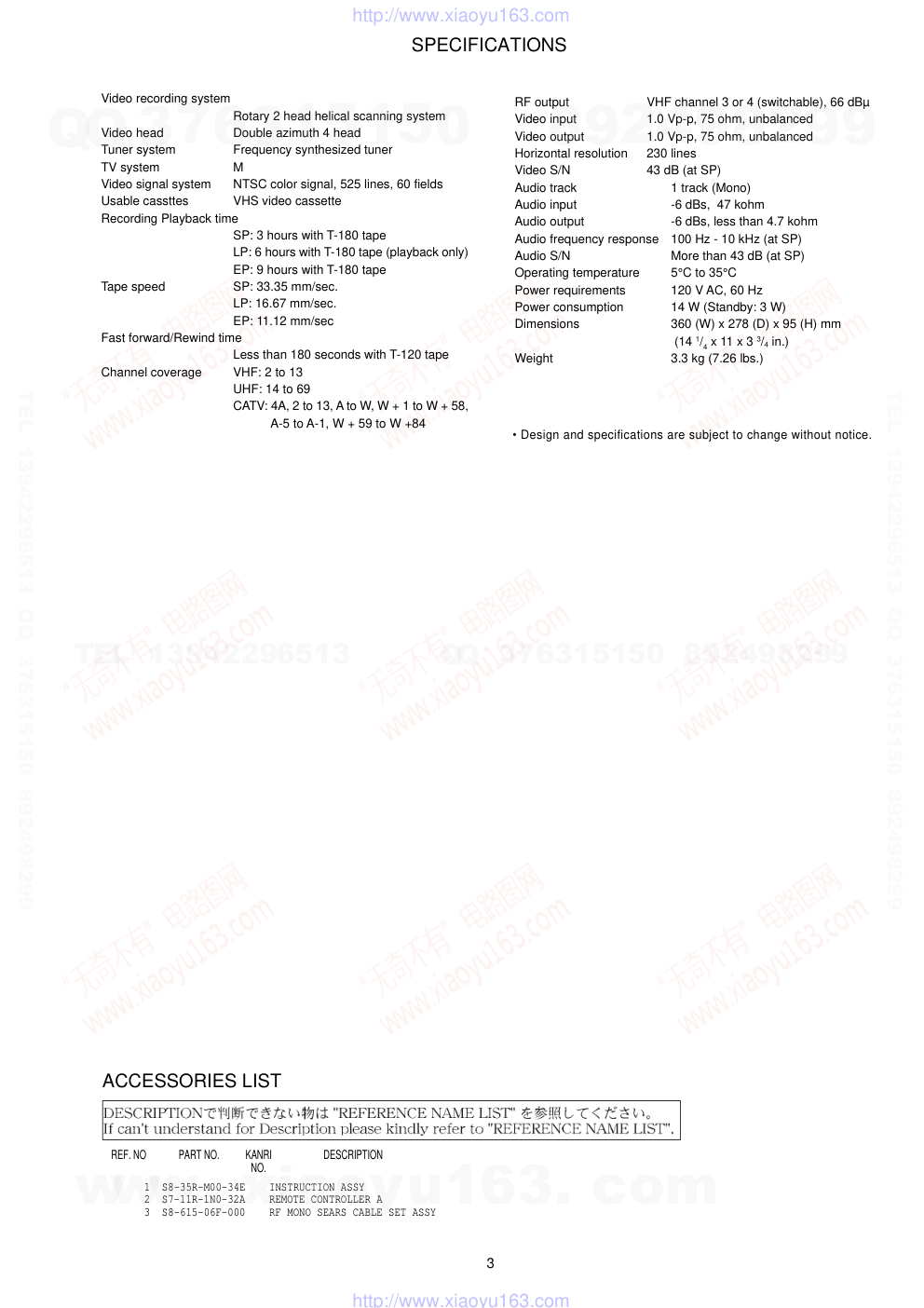
ACCESSORIES LIST
1 S8-35R-M00-34E INSTRUCTION ASSY
2 S7-11R-1N0-32A REMOTE CONTROLLER A
3 S8-615-06F-000 RF MONO SEARS CABLE SET ASSY
SPECIFICATIONS
• Design and specifications are subject to change without notice.
Video recording system
Rotary 2 head helical scanning system
Video head
Double azimuth 4 head
Tuner system
Frequency synthesized tuner
TV system
M
Video signal system
NTSC color signal, 525 lines, 60 fields
Usable cassttes
VHS video cassette
Recording Playback time
SP: 3 hours with T-180 tape
LP: 6 hours with T-180 tape (playback only)
EP: 9 hours with T-180 tape
Tape speed
SP: 33.35 mm/sec.
LP: 16.67 mm/sec.
EP: 11.12 mm/sec
Fast forward/Rewind time
Less than 180 seconds with T-120 tape
Channel coverage
VHF: 2 to 13
UHF: 14 to 69
CATV: 4A, 2 to 13, A to W, W + 1 to W + 58,
A-5 to A-1, W + 59 to W +84
RF output
VHF channel 3 or 4 (switchable), 66 dBµ
Video input
1.0 Vp-p, 75 ohm, unbalanced
Video output
1.0 Vp-p, 75 ohm, unbalanced
Horizontal resolution
230 lines
Video S/N
43 dB (at SP)
Audio track
1 track (Mono)
Audio input
-6 dBs, 47 kohm
Audio output
-6 dBs, less than 4.7 kohm
Audio frequency response
100 Hz - 10 kHz (at SP)
Audio S/N
More than 43 dB (at SP)
Operating temperature
5°C to 35°C
Power requirements
120 V AC, 60 Hz
Power consumption
14 W (Standby: 3 W)
Dimensions
360 (W) x 278 (D) x 95 (H) mm
(14 1/4 x 11 x 3 3/4 in.)
Weight
3.3 kg (7.26 lbs.)
www. xiaoyu163. com
QQ 376315150
9
9
2
8
9
4
2
9
8
TEL 13942296513
9
9
2
8
9
4
2
9
8
0
5
1
5
1
3
6
7
3
Q
Q
TEL 13942296513 QQ 376315150 892498299
TEL 13942296513 QQ 376315150 892498299
http://www.xiaoyu163.com
4
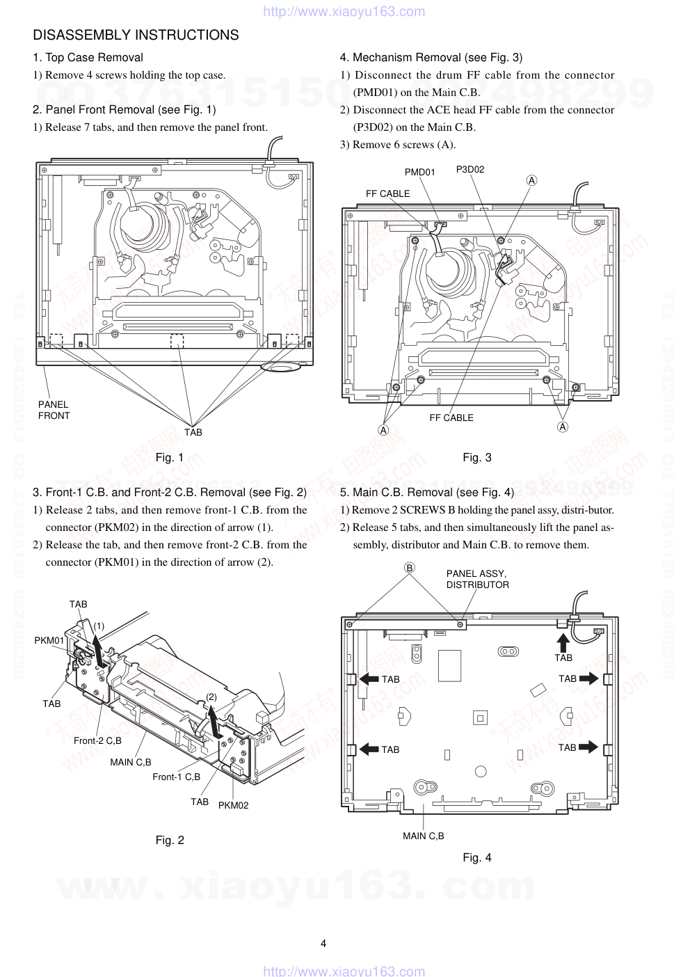
DISASSEMBLY INSTRUCTIONS
1. Top Case Removal
1) Remove 4 screws holding the top case.
2. Panel Front Removal (see Fig. 1)
1) Release 7 tabs, and then remove the panel front.
Fig. 1
3. Front-1 C.B. and Front-2 C.B. Removal (see Fig. 2)
1) Release 2 tabs, and then remove front-1 C.B. from the
connector (PKM02) in the direction of arrow (1).
2) Release the tab, and then remove front-2 C.B. from the
connector (PKM01) in the direction of arrow (2).
Fig. 2
4. Mechanism Removal (see Fig. 3)
1) Disconnect the drum FF cable from the connector
(PMD01) on the Main C.B.
2) Disconnect the ACE head FF cable from the connector
(P3D02) on the Main C.B.
3) Remove 6 screws (A).
Fig. 3
5. Main C.B. Removal (see Fig. 4)
1) Remove 2 SCREWS B holding the panel assy, distri-butor.
2) Release 5 tabs, and then simultaneously lift the panel as-
sembly, distributor and Main C.B. to remove them.
Fig. 4
TAB
PANEL
FRONT
PANEL ASSY,
DISTRIBUTOR
MAIN C,B
TAB
TAB
TAB
TAB
TAB
B
PKM02
TAB
TAB
TAB
(1)
(2)
PKM01
Front-1 C,B
Front-2 C,B
MAIN C,B
FF CABLE
FF CABLE
PMD01
P3D02
A
A
A
www. xiaoyu163. com
QQ 376315150
9
9
2
8
9
4
2
9
8
TEL 13942296513
9
9
2
8
9
4
2
9
8
0
5
1
5
1
3
6
7
3
Q
Q
TEL 13942296513 QQ 376315150 892498299
TEL 13942296513 QQ 376315150 892498299
http://www.xiaoyu163.com
5
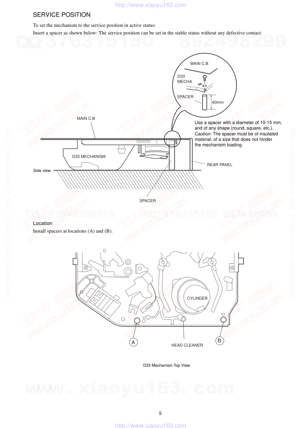
SERVICE POSITION
To set the mechanism to the service position in active status:
Insert a spacer as shown below: The service position can be set in the stable status without any defective contact.
Location
Install spacers at locations (A) and (B).
MAIN C.B
D33 MECHANISM
SPACER
60mm
MAIN C.B
D33
MECHA
SPACER
REAR PANEL
Use a spacer with a diameter of 10-15 mm,
and of any shape (round, square, etc.).
Caution: The spacer must be of insulated
material, of a size that does not hinder
the mechanism loading.
Side view
A
B
CYLINDER
HEAD CLEANER
D33 Mechanism Top View
www. xiaoyu163. com
QQ 376315150
9
9
2
8
9
4
2
9
8
TEL 13942296513
9
9
2
8
9
4
2
9
8
0
5
1
5
1
3
6
7
3
Q
Q
TEL 13942296513 QQ 376315150 892498299
TEL 13942296513 QQ 376315150 892498299
http://www.xiaoyu163.com
6
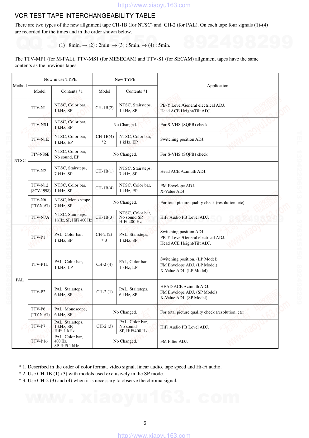
VCR TEST TAPE INTERCHANGEABILITY TABLE
There are two types of the new allgnment tape CH-1B (for NTSC) and CH-2 (for PAL). On each tape four signals (1)-(4)
are recorded for the times and in the order shown below.
(1) : 8min. → (2) : 2min. → (3) : 5min. → (4) : 5min.
The TTV-MP1 (for M-PAL), TTV-MS1 (for MESECAM) and TTV-S1 (for SECAM) allgnment tapes have the same
contents as the previous tapes.
Method
Now in use TYPE
Model
Contents *1
New TYPE
Model
Contents *1
Application
NTSC
PAL
TTV-N1
NTSC, Color bar,
1 kHz, SP
TTV-NS1
NTSC, Color bar,
1 kHz, SP
TTV-N1E
NTSC, Color bar,
1 kHz, EP
TTV-NS6E
NTSC, Color bar,
No sound, EP
TTV-N2
NTSC, Stairsteps,
7 kHz, SP
TTV-N12
(SCV-1998)
NTSC, Color bar,
1 kHz, SP
NTSC, Mono scope,
7 kHz, SP
TTV-N7A
NTSC, Stairsteps,
1 kHz, SP, HiFi 400 Hz
TTV-N6
(TTV-N06T)
TTV-P1
PAL, Color bar,
1 kHz, SP
TTV-P1L
PAL, Color bar,
1 kHz, LP
TTV-P2
PAL, Stairsteps,
6 kHz, SP
PAL, Monoscope,
6 kHz, SP
TTV-P6
(TTV-N06T)
TTV-P7
PAL, Stairsteps,
1 kHz, SP,
HiFi 1 kHz
TTV-P16
PAL, Color bar,
400 Hz,
SP, HiFi 1 kHz
CH-1B(2)
NTSC, Stairsteps,
1 kHz, SP
No Changed.
NTSC, Color bar,
1 kHz, EP
CH-1B(4)
*2
No Changed.
CH-1B(1)
NTSC, Stairsteps,
7 kHz, SP
CH-1B(4)
NTSC, Color bar,
1 kHz, EP
No Changed.
CH-1B(3)
NTSC, Color bar,
No sound SP,
HiFi 400 Hz
PAL, Stairsteps,
1 kHz, SP
CH-2 (2)
* 3
CH-2 (4)
PAL, Color bar,
1 kHz, LP
CH-2 (1)
PAL, Stairsteps,
6 kHz, SP
No Changed.
CH-2 (3)
PAL, Color bar,
No sound
SP, HiFi400 Hz
No Changed.
PB-Y Level/General electrical ADJ.
Head ACE Height/Tilt ADJ.
For S-VHS (SQPB) check
Switching position ADJ.
For S-VHS (SQPB) check
Head ACE Azimuth ADJ.
FM Envelope ADJ.
X-Value ADJ.
For total picture quality check (resolution, etc)
HiFi Audio PB Level ADJ.
Switching position ADJ.
PB-Y Level/General electrical ADJ.
Head ACE Height/Tilt ADJ.
Switching position. (LP Model)
FM Envelope ADJ. (LP Model)
X-Value ADJ. (LP Model)
HEAD ACE Azimuth ADJ.
FM Envelope ADJ. (SP Model)
X-Value ADJ. (SP Model)
For total picture quality check (resolution, etc)
FM Filter ADJ.
HiFi Audio PB Level ADJ.
* 1. Described in the order of color format. video signal. linear audio. tape speed and Hi-Fi audio.
* 2. Use CH-1B (1)-(3) with models used exclusively in the SP mode.
* 3. Use CH-2 (3) and (4) when it is necessary to observe the chroma signal.
www. xiaoyu163. com
QQ 376315150
9
9
2
8
9
4
2
9
8
TEL 13942296513
9
9
2
8
9
4
2
9
8
0
5
1
5
1
3
6
7
3
Q
Q
TEL 13942296513 QQ 376315150 892498299
TEL 13942296513 QQ 376315150 892498299
http://www.xiaoyu163.com
7
REF. NO
PART NO.
KANRI
DESCRIPTION
NO.
REF. NO
PART NO.
KANRI
DESCRIPTION
NO.
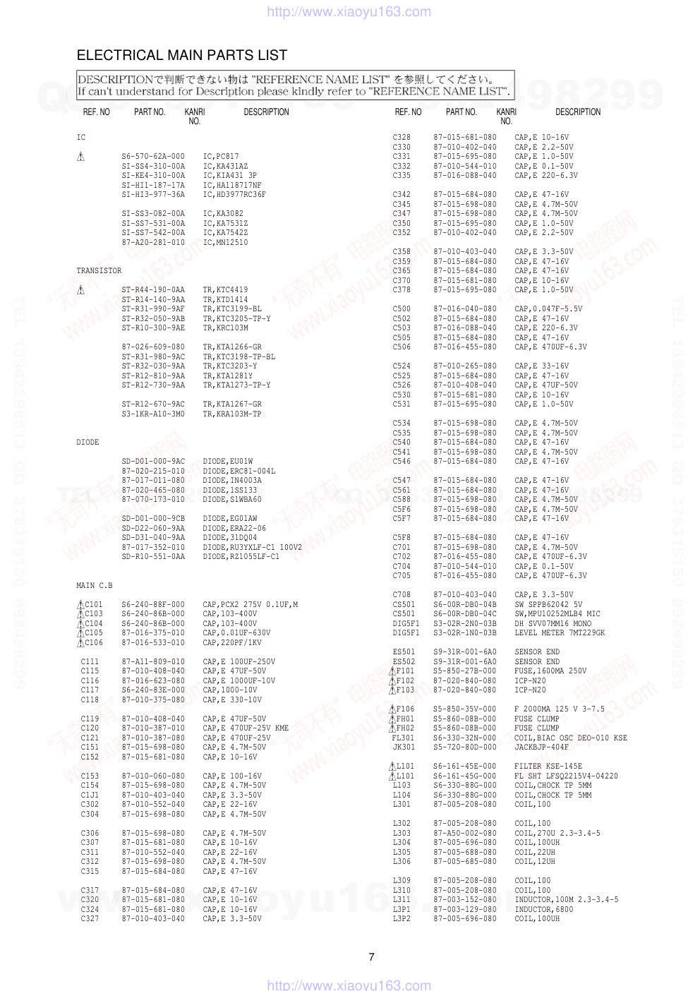
ELECTRICAL MAIN PARTS LIST
IC
!
S6-570-62A-000 IC,PC817
SI-SS4-310-00A IC,KA431AZ
SI-KE4-310-00A IC,KIA431 3P
SI-HI1-187-17A IC,HA118717NF
SI-HI3-977-36A IC,HD3977RC36F
SI-SS3-082-00A IC,KA3082
SI-SS7-531-00A IC,KA7531Z
SI-SS7-542-00A IC,KA7542Z
87-A20-281-010 IC,MN12510
TRANSISTOR
!
ST-R44-190-0AA TR,KTC4419
ST-R14-140-9AA TR,KTD1414
ST-R31-990-9AF TR,KTC3199-BL
ST-R32-050-9AB TR,KTC3205-TP-Y
ST-R10-300-9AE TR,KRC103M
87-026-609-080 TR,KTA1266-GR
ST-R31-980-9AC TR,KTC3198-TP-BL
ST-R32-030-9AA TR,KTC3203-Y
ST-R12-810-9AA TR,KTA1281Y
ST-R12-730-9AA TR,KTA1273-TP-Y
ST-R12-670-9AC TR,KTA1267-GR
S3-1KR-A10-3M0 TR,KRA103M-TP
DIODE
SD-D01-000-9AC DIODE,EU01W
87-020-215-010 DIODE,ERC81-004L
87-017-011-080 DIODE,IN4003A
87-020-465-080 DIODE,1SS133
87-070-173-010 DIODE,S1WBA60
SD-D01-000-9CB DIODE,EG01AW
SD-D22-060-9AA DIODE,ERA22-06
SD-D31-040-9AA DIODE,31DQ04
87-017-352-010 DIODE,RU3YXLF-C1 100V2
SD-R10-551-0AA DIODE,RZ1055LF-C1
MAIN C.B
!C101
S6-240-88F-000 CAP,PCX2 275V 0.1UF,M
!C103
S6-240-86B-000 CAP,103-400V
!C104
S6-240-86B-000 CAP,103-400V
!C105
87-016-375-010 CAP,0.01UF-630V
!C106
87-016-533-010 CAP,220PF/1KV
C111 87-A11-809-010 CAP,E 100UF-250V
C115 87-010-408-040 CAP,E 47UF-50V
C116 87-016-623-080 CAP,E 1000UF-10V
C117 S6-240-83E-000 CAP,1000-10V
C118 87-010-375-080 CAP,E 330-10V
C119 87-010-408-040 CAP,E 47UF-50V
C120 87-010-387-010 CAP,E 470UF-25V KME
C121 87-010-387-080 CAP,E 470UF-25V
C151 87-015-698-080 CAP,E 4.7M-50V
C152 87-015-681-080 CAP,E 10-16V
C153 87-010-060-080 CAP,E 100-16V
C154 87-015-698-080 CAP,E 4.7M-50V
C1J1 87-010-403-040 CAP,E 3.3-50V
C302 87-010-552-040 CAP,E 22-16V
C304 87-015-698-080 CAP,E 4.7M-50V
C306 87-015-698-080 CAP,E 4.7M-50V
C307 87-015-681-080 CAP,E 10-16V
C311 87-010-552-040 CAP,E 22-16V
C312 87-015-698-080 CAP,E 4.7M-50V
C315 87-015-684-080 CAP,E 47-16V
C317 87-015-684-080 CAP,E 47-16V
C320 87-015-681-080 CAP,E 10-16V
C324 87-015-681-080 CAP,E 10-16V
C327 87-010-403-040 CAP,E 3.3-50V
C328 87-015-681-080 CAP,E 10-16V
C330 87-010-402-040 CAP,E 2.2-50V
C331 87-015-695-080 CAP,E 1.0-50V
C332 87-010-544-010 CAP,E 0.1-50V
C335 87-016-088-040 CAP,E 220-6.3V
C342 87-015-684-080 CAP,E 47-16V
C345 87-015-698-080 CAP,E 4.7M-50V
C347 87-015-698-080 CAP,E 4.7M-50V
C350 87-015-695-080 CAP,E 1.0-50V
C352 87-010-402-040 CAP,E 2.2-50V
C358 87-010-403-040 CAP,E 3.3-50V
C359 87-015-684-080 CAP,E 47-16V
C365 87-015-684-080 CAP,E 47-16V
C370 87-015-681-080 CAP,E 10-16V
C378 87-015-695-080 CAP,E 1.0-50V
C500 87-016-040-080 CAP,0.047F-5.5V
C502 87-015-684-080 CAP,E 47-16V
C503 87-016-088-040 CAP,E 220-6.3V
C505 87-015-684-080 CAP,E 47-16V
C506 87-016-455-080 CAP,E 470UF-6.3V
C524 87-010-265-080 CAP,E 33-16V
C525 87-015-684-080 CAP,E 47-16V
C526 87-010-408-040 CAP,E 47UF-50V
C530 87-015-681-080 CAP,E 10-16V
C531 87-015-695-080 CAP,E 1.0-50V
C534 87-015-698-080 CAP,E 4.7M-50V
C535 87-015-698-080 CAP,E 4.7M-50V
C540 87-015-684-080 CAP,E 47-16V
C541 87-015-698-080 CAP,E 4.7M-50V
C546 87-015-684-080 CAP,E 47-16V
C547 87-015-684-080 CAP,E 47-16V
C561 87-015-684-080 CAP,E 47-16V
C588 87-015-698-080 CAP,E 4.7M-50V
C5F6 87-015-698-080 CAP,E 4.7M-50V
C5F7 87-015-684-080 CAP,E 47-16V
C5F8 87-015-684-080 CAP,E 47-16V
C701 87-015-698-080 CAP,E 4.7M-50V
C702 87-016-455-080 CAP,E 470UF-6.3V
C704 87-010-544-010 CAP,E 0.1-50V
C705 87-016-455-080 CAP,E 470UF-6.3V
C708 87-010-403-040 CAP,E 3.3-50V
CS501 S6-00R-DB0-04B SW SPPB62042 5V
CS501 S6-00R-DB0-04C SW,MPU10252MLB4 MIC
DIG5F1 S3-02R-2N0-03B DH SVV07MM16 MONO
DIG5F1 S3-02R-1N0-03B LEVEL METER 7MT229GK
ES501 S9-31R-001-6A0 SENSOR END
ES502 S9-31R-001-6A0 SENSOR END
!F101
S5-850-27B-000 FUSE,1600MA 250V
!F102
87-020-840-080 ICP-N20
!F103
87-020-840-080 ICP-N20
!F106
S5-850-35V-000 F 2000MA 125 V 3-7.5
!FH01
S5-860-08B-000 FUSE CLUMP
!FH02
S5-860-08B-000 FUSE CLUMP
FL301
S6-330-32N-000 COIL,BIAC OSC DEO-010 KSE
JK301 S5-720-80D-000 JACKBJP-404F
!L101
S6-161-45E-000 FILTER KSE-145E
!L101
S6-161-45G-000 FL SHT LFSQ2215V4-04220
L103 S6-330-88G-000 COIL,CHOCK TP 5MM
L104 S6-330-88G-000 COIL,CHOCK TP 5MM
L301 87-005-208-080 COIL,100
L302 87-005-208-080 COIL,100
L303 87-A50-002-080 COIL,270U 2.3-3.4-5
L304 87-005-696-080 COIL,100UH
L305 87-005-688-080 COIL,22UH
L306 87-005-685-080 COIL,12UH
L309 87-005-208-080 COIL,100
L310 87-005-208-080 COIL,100
L311 87-003-152-080 INDUCTOR,100M 2.3-3.4-5
L3P1 87-003-129-080 INDUCTOR,6800
L3P2 87-005-696-080 COIL,100UH
www. xiaoyu163. com
QQ 376315150
9
9
2
8
9
4
2
9
8
TEL 13942296513
9
9
2
8
9
4
2
9
8
0
5
1
5
1
3
6
7
3
Q
Q
TEL 13942296513 QQ 376315150 892498299
TEL 13942296513 QQ 376315150 892498299
http://www.xiaoyu163.com
8
REF. NO
PART NO.
KANRI
DESCRIPTION
NO.
L501 87-005-208-080 COIL,100
L506 87-005-682-080 COIL,6.80UH
L701 87-005-693-080 COIL,56M K 6-6-5
LD501 S9-31R-001-7A0 LED
MS501 S6-00R-PY0-01B SW,MMS00420ZMBO MIC
P3D01 S5-612-34Y-000 CONN,6P
P3D02 S6-30R-5S0-08E CONN,6P
P3D03 S5-612-51B-000 CONN,2P
PMC01 S6-30R-2P0-05C CONN,8P
PMD01 S5-612-34V-000 CONN,7P
PMK01 S6-724-34B-000 CONN,5P
PMK02 S5-618-43J-000 CONN,10P
PML01 S6-30R-2S0-11A CONN,2P
!PW101
S5-612-92B-000 CONN,2P
!R101
S6-140-13C-000 RES,RCR50,2.2M J M15
!R102
S6-140-07K-000 RES,CEM 3.3-2W
!R104
SR-S33-02K-619 RES,M/F 33K-2W
!R105
SR-S12-00J-619 RES,M/F 120-1W
RC5F1 S7-12R-293-8GA REMOCON RECEIVER
RS501 S5-00R-AB0-02A SENSOR GP1S566
RS502 S5-00R-AB0-02A SENSOR GP1S566
SW701 S5-560-27C-000 SW,SLIDE
!T101
S6-420-21E-000 PT,KSE-021E
TU701 S7-00R-N3L-04A TUNER TADC-H002F
!V101
S6-560-04C-000 V SVC681D-10A
VR501 S6-130-32U-000 RES,VARIABLE (100K)
X301 S2-02R-135-71E X’TAL,3.579675MHZ
X301 S2-02R-135-71C X’TAL,3.579690MHZ
X501 S2-02R-110-0AC X’TAL,10MHZ
X501 S2-02R-110-0AE X’TAL,10MHZ 30PPM
X502 S5-290-01K-000 X’TAL,32.768KHZ
X502 S5-290-01B-000 X’TAL,32.768KHZ
X503 S2-02R-114-3AA X’TAL,14.317872
X503 S2-02R-114-3AC X’TAL,14.317872MHZ
X503 S2-02R-114-3AE X’TAL,14.317872MHZ
X5F1 S6-180-10B-000 X’TAL,4MHZ
ZD101 S9-7U0-3R3-1B0 ZENER,MTZ3.3B
ZD151 SD-Z13-000-9AC ZENER,MTZ13B
ZD152 87-070-334-070 ZENER,MTZ10B
ZD501 SM-TZ6-8CT-000 ZENER,MTZ6.8C
ZD502 83-NEG-677-080 DIODE,MTZ5.6B
ZD503 87-A40-476-010 ZENER,MTZ6.2A
ZD5F1 SD-Z51-000-9HA ZENER,MTZ5.1B 0.5W
ZD701 87-002-743-080 ZENER,MTZ33B
FRONT-1 C.B
PMK02 S5-618-44J-000 CONN,10P
SW5A1 S5-562-82C-000 SW,SKQNQED ALPS 5MM
SW5A2 S5-562-82C-000 SW,SKQNQED ALPS 5MM
SW5A3 S5-562-82C-000 SW,SKQNQED ALPS 5MM
SW5A4 S5-562-82C-000 SW,SKQNQED ALPS 5MM
SW5A5 S5-562-82C-000 SW,SKQNQED ALPS 5MM
SW5A6 S5-562-82C-000 SW,SKQNQED ALPS 5MM
FRONT-2 C.B
LD5A1 SD-L53-110-0AA LED,SG5311(GRN)
PMK01 S5-610-36D-000 CONN,5P
SW5A0 S5-562-82C-000 SW,SKQNQED ALPS 5MM
SW5A7 S5-562-82C-000 SW,SKQNQED ALPS 5MM
SW5A8 S5-562-82C-000 SW,SKQNQED ALPS 5MM
SW5A9 S5-562-82C-000 SW,SKQNQED ALPS 5MM
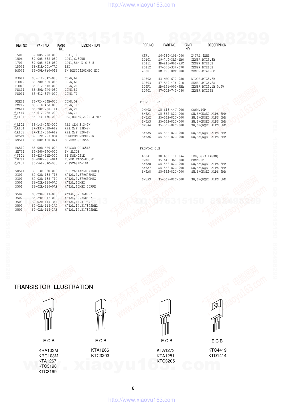
TRANSISTOR ILLUSTRATION
KRA103M
KRC103M
KTA1267
KTC3198
KTC3199
KTA1266
KTC3203
KTA1273
KTA1281
KTC3205
KTC4419
KTD1414
E C B
E C B
E C B
E C B
REF. NO
PART NO.
KANRI
DESCRIPTION
NO.
www. xiaoyu163. com
QQ 376315150
9
9
2
8
9
4
2
9
8
TEL 13942296513
9
9
2
8
9
4
2
9
8
0
5
1
5
1
3
6
7
3
Q
Q
TEL 13942296513 QQ 376315150 892498299
TEL 13942296513 QQ 376315150 892498299
http://www.xiaoyu163.com
9
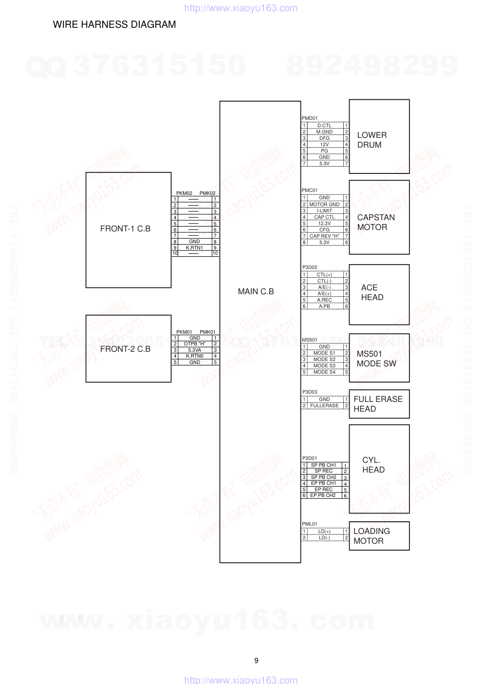
WIRE HARNESS DIAGRAM
1
2
3
4
5
6
7
D.CTL
M.GND
DFG
12V
PG
GND
5.3V
1
2
3
4
5
6
7
1
2
3
4
5
6
7
8
GND
MOTOR GND
I-LIMIT
CAP CTL
12.3V
CFG
CAP REV "H"
5.3V
1
2
3
4
5
6
7
8
1
2
3
4
5
6
CTL(+)
CTL(-)
A/E(-)
A/E(+)
A.REC
A.PB
1
2
3
4
5
6
1
2
3
4
5
GND
MODE S1
MODE S2
MODE S3
MODE S4
1
2
3
4
5
1
2
GND
FULLERASE
1
2
LOWER
DRUM
CAPSTAN
MOTOR
MS501
MODE SW
FULL ERASE
HEAD
CYL.
HEAD
MAIN C.B
FRONT-2 C.B
FRONT-1 C.B
ACE
HEAD
PMD01
PMC01
P3D02
MS501
P3D03
1
2
LD(+)
LD(-)
1
2 LOADING
MOTOR
PML01
P3D01
1
SP PB CH1
SP REC
SP PB CH2
2
3
4
5
6
1
2
3
4
5
6
EP PB CH1
EP PB CH2
EP REC
1
PKM01
GND
OTPB "H"
5.3VA
K.RTN0
GND
PMK01
2
3
4
5
1
2
3
4
5
1
PKM02
PMK02
2
3
4
5
6
7
1
2
3
4
5
6
7
8
8
GND
10
10
K.RTN1
9
9
www. xiaoyu163. com
QQ 376315150
9
9
2
8
9
4
2
9
8
TEL 13942296513
9
9
2
8
9
4
2
9
8
0
5
1
5
1
3
6
7
3
Q
Q
TEL 13942296513 QQ 376315150 892498299
TEL 13942296513 QQ 376315150 892498299
http://www.xiaoyu163.com
10
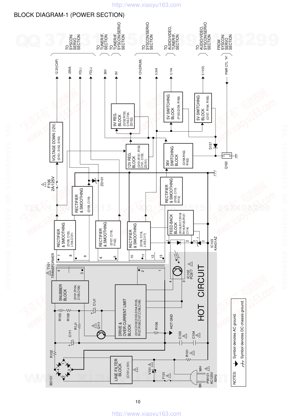
BLOCK DIAGRAM-1 (POWER SECTION)
NOTES:
Symbol denotes AC ground.
Symbol denotes DC chassis ground.
HOT CIRCUIT
BD101
R102
C111
R1J1
Q111
R106
C103
C104
R101
HOT GND
F101
V101
BK
WH
PW101
AC120V
60Hz
R103
R109
4
7
8
9
6
5
10
2
1
4
3
11
13
12
1
2
IC102
PC817
IC103
KA431AZ
3
T101
TRANSFORMER
4
2
3
1
(C101,L101)
LINE FILTER
BLOCK
RECTIFIER
& SMOOTHING
(Q152,R153,
C153,C154,
ZD152)
9V REG.
BLOCK
(Q151,R151 ,R152
C151, C152,
ZD151)
12V REG.
BLOCK
36V
SWITCHING
BLOCK
(D105, C115
R112)
RECTIFIER
& SMOOTHING
FEED-BACK
BLOCK
(R116,R117,R118
R119,R120,R121
C114)
RECTIFIER
& SMOOTHING
RECTIFIER
& SMOOTHING
DRIVE &
OVER CURRENT LIMIT
BLOCK
+
C1J1
+
12.3V(CAP)
-29VA
FD(-)
FD(+)
36V
9V
12V(DRUM)
5.1VA
5.3VA
5.1V(D)
SNUBBER
BLOCK
(Q112,D102,D103,D104,R105,
R107,R108,C107,C108,C109)
(D101,R104,
C105,C106)
(D107, C118,
F102)
(D109, C120,
L104,C121)
VOLTAGE DOWN (12V)
(D151, D152, D153)
(D106, C116,
L103,C117)
(Q158,R162,
R163)
5V SWITCHING
BLOCK
(Q157, R164, R165)
PWR CTL "H"
RECTIFIER
& SMOOTHING
(D108, C119)
ZD101
F106
2A/125V
5V SWITCHING
BLOCK
(F103,Q159, R166)
D157
Q160
FROM
SYSCON/
SERVO
SECTION
TO
SYSCON/SERVO
SECTION
TO
SYSCON/
SERVO
SECTION
TO
AUDIO/VIDEO,
TUNER/IF,
SECTION
TO
TUNER/IF,
SYSCON/SERVO
SECTION
TO
AUDIO/VIDEO,
SYSCON/SERVO
SECTION
TO
TUNER/IF,
SECTION
2
1
3
!
!
!
!
!
!
!
!
!
!
!
www. xiaoyu163. com
QQ 376315150
9
9
2
8
9
4
2
9
8
TEL 13942296513
9
9
2
8
9
4
2
9
8
0
5
1
5
1
3
6
7
3
Q
Q
TEL 13942296513 QQ 376315150 892498299
TEL 13942296513 QQ 376315150 892498299
http://www.xiaoyu163.com
11
BLOCK DIAGRAM-2 (AUDIO SECTION)
T.A.IN
L.A.IN 1
9
8
7
VCA
DET
REC
AMP
AMP
PB EQ
AMP
4
11
2
AUDIO
REC/PB
HEAD
AUDIO
REC/PB
HEAD
AUDIO
ERASE
HEAD
:REC AUDIO SIGNAL
:PB AUDIO SIGNAL
17
A.OUT
17
A.IN
TU701
TUNER
JK301
AUDIO
IN
JK301
AUDIO
OUT
BIAS OSC
(FL301,Q301)
SW
(Q302,Q303)
SW
(Q304-Q306)
FULL
ERASE
HEAD
5.1V(D)
5.1V(D)
REC "H"
TO
SYSCON/SERVO
SECTION
IC301
HA118717NF
VIDEO/AUDIO
PROCESSOR
www. xiaoyu163. com
QQ 376315150
9
9
2
8
9
4
2
9
8
TEL 13942296513
9
9
2
8
9
4
2
9
8
0
5
1
5
1
3
6
7
3
Q
Q
TEL 13942296513 QQ 376315150 892498299
TEL 13942296513 QQ 376315150 892498299
http://www.xiaoyu163.com
12
BLOCK DIAGRAM-3 (TUNER SECTION)
18
17
16
15
14
13
12
11
10
9
8
7
6
5
4
3
2
1
SW701
CH
CH3
CH4
TU701
N.C
A.OUT
20
19
V.OUT
AFT
IF
N.C
30V
N.C
N.C
REG 5V
DATA
CLOCK
ENABLE
N.C
RF AGC
V.IN
CONTROL
REG 5V
CH S/W
A.IN
BUFFER
Q701
VIDEO
VCR 'H'
CLOCK
AFT
TU VIDEO
36V
5.1V(A)
DATA
TU AUDIO
MOD.A.IN
LINE VIDEO
VHF/UHF
IN FROM ANT
OUT TO TV
From
SYSCON/SERVO
SECTION
To/From
AUDIO/VIDEO
SECTION
From
POWER
SECTION
:REC AUDIO SIGNAL
:PB AUDIO SIGNAL
:REC VIDEO SIGNAL
:PB VIDEO SIGNAL
AFT: AUTOMATIC FREQUENCY CONTROL
www. xiaoyu163. com
QQ 376315150
9
9
2
8
9
4
2
9
8
TEL 13942296513
9
9
2
8
9
4
2
9
8
0
5
1
5
1
3
6
7
3
Q
Q
TEL 13942296513 QQ 376315150 892498299
TEL 13942296513 QQ 376315150 892498299
http://www.xiaoyu163.com
14
13
BLOCK DIAGRAM-4 (VIDEO SECTION)
+
51
52
42
39
44
46
35
29
21
26
24
23
18
19
50
22
20
14
13
15
VIDEO IN
60
58
62
69
63
73
71
81
87
88
VIDEO
AGC
CLEAR
SYNC
V. OUT
D-V SYNC
Y-CCD
C-CCD
CLOCK Drive
6dB
AMP
FBC
Video ALC
SQUEL CH
C-SYNC
LPF
AGC DET
CLAMP
Y-LPF
YNR
CLAMP
SYNC
SEP
D.E.
C-LPF
SPF
ACC
C-LPF
NL Emph
LPF
LPF
HPF
VCA
TRAP
FBC
ALC
Main
Conv2
Main
Conv2
APC/ACC
DET
Main
Emph
FM
MOD
REC
Trap
REC-AMP
SP CH2
REC-AMP
SP CH1
MIX
ATT
B.E
C.K
CCD
LPF
L-DET
VCA
(-4dB)
f0=1.68M
f/0DEV
Adjst
X-tal
VCO/OSC
Serial Cont
interface
DATA
CLOCK
V.H/SW30
SP REC
+
+
51
42
39
44
14
13
62
69
63
81
89
84
IC301
HA118717NF
AUDIO/VIDEO
PROCESSOR
79
78
22
73
71
52
56
21
26
24
23
18
19
50
60
58
55
54
35
46
V. OUT
D-V SYNC
Y-CCD
C-CCD
CLOCK Drive
FBC
Video ALC
LPF
REC-AMP
SP CH1
DATA
CLOCK
V.H/SW30
V.ENV
SP PB CH2
SP PB CH1
Serial Cont
interface
X-tal
VCO/OSC
TRAP
FM AGC
P.EQ
G.EQ
D LIM
Y LPF
Main
De-Empf
DEMO
S LPF
2M LPF
ACC
CTL Trap
fh Trap
HIFI Trap
C LPF
DEALY
MIX
AMP
SQUEL CH
CLEAR
SYNC
CLAMP
CLAMP
Sharpness
CONTROL
YNR
NC
SYNC SEP
C-SYNC
NL
De-eMPH
VCA
C.K
LPF
BD
BPF
CCD LPF
APC/ACC
DET
L- DET
Main
Conv2
Main
Conv1
To/From
SYSCON/SERVO
SECTION
From
SYSCON/SERVO
SECTION
From
CYL.HEADS
X301
3.579MHz
X301
3.579MHz
From
SYSCON/SERVO
SECTION
To/From
SYSCON/SERVO
SECTION
From
TUNER/IF
SECTION
To/From
SYSCON/SERVO
SECTION
From
SYSCON/SERVO
SECTION
To
SYSCON/SERVO
SECTION
To
CYL.HEADS
87
88
REC-AMP
EP CH2
REC-AMP
EP CH1
EP REC
REC-AMP
SP CH2
86
94
REC-AMP
EP CH1
EP PB CH2
EP PB CH1
REC-AMP
EP CH2
91
SP
CH2
CH1
CH2
CH1
EP
ATT
-10dB
ATT
-10dB
ATT
-10dB
31
30
28
JK301
VIDEO
IN
:PB CHROMA SIGNAL
:PB Y SIGNAL
:REC CHROMA SIGNAL
:REC Y SIGNAL
:REC VIDEO SIGNAL
:PB VIDEO SIGNAL
IC301
HA118717NF
AUDIO/VIDEO
PROCESSOR
• PB MODE
• REC MODE
D LIM: Double Limit
FBC:
Feed Back Clamp
YNR:
Y Noise Reduction
APC:
Automatic Phase Control
ACC:
Automatic Color Control
w w w
.
x i a o y u 1 6 3 .
c o m
Q Q
3 7 6 3 1 5 1 5 0
9
9
2
8
9
4
2
9
8
T E L
1 3 9 4 2 2 9 6 5 1 3
9
9
2
8
9
4
2
9
8
0
5
1
5
1
3
6
7
3
Q
Q
TEL 13942296513 QQ 376315150 892498299
TEL 13942296513 QQ 376315150 892498299
http://www.xiaoyu163.com
16
15
BLOCK DIAGRAM-5 (SYSTEM CONTROL SECTION)
GND
MODE S1
MODE S2
MODE S3
MODE S4
MODE S/W
T-UP REEL
T-UP END
PML01
SUP REEL
(CST.SW)
5.1VD
CS501
5.3VA
5.3VA
ES501
R550
LD501
DECK IR LED
R553
R555
RS501
RS502
R556
Q514
Q515
R558
R548
C552
R5C6
C506
C501
C500
R542
D501
R541
R539
MS501
X501
10MHz
32.768KHz
OSC
OSC
X502
M
LD +
LD
2
1
L/D MOTOR
12V(DRUM)
R526
R525
5
6
4
7
8
1
10
Vcc 1
Vcc 2
OUT 1
OUT 2
GND
IN 2
IN 1
Vref
IC502
KA3082
LOADING MOTOR
DRIVE
C529
ZD501
2
1
2
RESET
Vcc
3
5.3VA
L501
5.3VA
9V
IC504
KA7531Z
RESET
+
+
C561
C521
+
C504
+C503
R516
R557
C536
SUP END
ES502
R564
C537
R544
OSC
R/C
PMK01
PMK01
4
RC5F1
TSOP1238SP1
REMOCON
SENSOR
L506
R517
C518
C519
OSC
X503
14.3178MHz
+
C532
C505
TO DECK
ZD502
ZD503
Q522
Q503
Q501
CV IN
77
76
75
74
1
5
57
4
17
34 35 36 37
22
41
16
IC501
HD3977RC36F
SYSCON/SERVO
PROCESSOR
MODE S1
I-Limit
MODE S2
MODE S3
MODE S4
T-UP Sensor
T-UP Reel
SUP Reel
CST IN
Vcc (SYSCON)
Vcc (SERVO)
CAP. PWM
CTL +
CTL -
DFG
CFG
CAP. RVS 'H'
CAP. ACCEL
DRUM ADJ.
V. ENV
V.H.SW30
C.Sync
DPG
D.V.Sync
72
73 OSC2
X1
X2
OSC1
70
69
53
52
50
fsc IN
13
KEY RTN 0
14
KEY RTN 1
fsc OUT
Dosc IN
19 LD -
LD +
20
31 32
38
40 61 80 81
12
24
87
26
39
27
25
78
DRUM PWM
42
Vcc (OSD)
3 SUP END Sensor
51
Dosc OUT
82
15
Vcc (A/D)
91
55
VCR 'H'
PLL DATA
PLL CLK
CV OUT
9
AFT
6
SQPB IN
90
45
POWER FAIL
89
A. MUTE 'H'
REC 'H'
79
62
43
54
C. sync (NOR)
C. sync
55
PWR CTL 'H'
2
Vcc
3
IIC DATA
IIC CLK
90
91
IC505
KA7542Z
POWER FAIL DET.
1
1
2
3
4
5
R
R
PKM02
PMK02
9
FRONT-2 C.B
FRONT-1 C.B
CTL.GAIN ADJ
CTL1
CTL2
CTL3
CTL OUT
CTL.
GAIN
ADJ
Q5J1
FROM
POWER
SECTION
TO/FROM
TUNER/IF
SECTION
TO
POWER
SECTION
TO
AUDIO/VIDEO
SECTION
1
2
3
4
1
2
3
4
1
SW5A7
CH UP
SW5A8
CH DOWN
SW5A0
OPTB
SW5A9
ONE-TOUCH
PLAYBACK
SW5A1
REC/ITR
SW5A2
REW
SW5A3
PLAY
SW5A4
F.FWD
SW5A5
STOP
SW5A6
PAUSE/
STILL
FLD ENV 94
FLD DATA OUT 97
FLD DATA IN
FLD CLK
96
95
1
P15
P16
NC
NC
G1
G2
G3
G4
G5
P3
P2
P1
POWER LED
SHUTTLE4
SHUTTLE3
SHUTTLE2
SHUTTLE1
DATA OUT
DATA IN
CLK
2
3
4
5
6
7
8
9 10 11
33 32 31 30 29 28 27 26 25 24 23
44
43
42
41
40
39
38
37
36
35
34 P4
P5
P6
P7
P8
P9
P10
P11
P12
P13
P14
12
13
14
15
16
17
18
19
20
21
22
G6
G7
G8
G9
VPP
IC5F1
MN12510
DISPLAY DRIVE
VDD
OSC1
OSC2
VSS
ENA
OSC
X5F1 4MHz
FD (+)
FD (-)
5.3VA
-29VA
FROM
POWER
SECTION
DIG5F1 DISPLAY
Q506
Q509
D502
R503
w w w
.
x i a o y u 1 6 3 .
c o m
Q Q
3 7 6 3 1 5 1 5 0
9
9
2
8
9
4
2
9
8
T E L
1 3 9 4 2 2 9 6 5 1 3
9
9
2
8
9
4
2
9
8
0
5
1
5
1
3
6
7
3
Q
Q
TEL 13942296513 QQ 376315150 892498299
TEL 13942296513 QQ 376315150 892498299
http://www.xiaoyu163.com
18
17
SCHEMATIC DIAGRAM-1 (POWER SECTION)
NOTES) Symbol denotes AC ground.
NOTES) Symbol denotes DC chassis ground.
NOTES) Warning
NOTES) Parts that are shaded are critical
NOTES) With respect to risk of fire or
NOTES) electricial shock.
MAIN (POWER SECTION) C.B
AC120V
60Hz
C101
0.1u/275V
ICP-N20
ICP-N20
(0.8A/50V)
12.3V(CAP)
To
AUDIO/VIDEO
SECTION
To
TUNER/IF
SECTION
Front
SYSCON/SERVO
SECTION
To
SYSCON/SERVO
SECTION
To
SYSCON/SERVO
SECTION
2
1
3
IC103
KA431AZ
(KIA431)
IC102
PC817
35.5
35.6
34.9
5.3
5.2
4.6
5.3
5.1
5.7
15.0
12.1
12.7
12.1
9.8
9.2
ONE VOLTAGE:PB OR REC MODE
: HOTCIRCUIT
*
w w w
.
x i a o y u 1 6 3 .
c o m
Q Q
3 7 6 3 1 5 1 5 0
9
9
2
8
9
4
2
9
8
T E L
1 3 9 4 2 2 9 6 5 1 3
9
9
2
8
9
4
2
9
8
0
5
1
5
1
3
6
7
3
Q
Q
TEL 13942296513 QQ 376315150 892498299
TEL 13942296513 QQ 376315150 892498299
http://www.xiaoyu163.com
20
19
SCHEMATIC DIAGRAM-2 (AUDIO/VIDEO SECTION)
VIDEO
AUDIO
IN
OUT
IN
OUT
From
POWER
SECTION
To/From
SYSCON/SERVO
SECTION
TU VIDEO
LINE VIDEO
From
TUNER/IF
SECTION
(1/6)
(1/4)
R
R
EMPH
VIDEO/AUDIO
PROCESSOR
(6/6)
(2/4)
(3/4)
(4/4)
To/From
SYSCON/SERVO
SECTION
SQPB IN
IN
(4/6)
(3/6)
(2/6)
809 MOD.A.IN
To/From
TUNER/IF
SECTION
(5/6)
3.5796MHz
X301
MAIN (AUDIO/VIDEO SECTION) C.B
TU AUDIO
VIDEO
5.1V(D)
5.1V(A)
2.5
2.5
0
0
0
0
2.5
0
2.8
2.5
2.5
2.5
2.5
2.5
5.0
1.6
(2.1)
1.6
(2.1) 2.3
-
(0)
1.8
(0)
2.1
2.8
2.8
2.1
2.2
(2.4)
2.8
2.1
1.4
2.1
0
2.8
1.9
2.8
-
-
0
0
0
2.7
2.7
1.7
5.1
5.1
5.1
5.1
5.1
2.5
0
0
0
0
-
-
-
2.8
1.9
2.1
2.8
-
2.8
2.8
2.8
5.0
-
-
-
2.3
(0)
5.0
5.0
0
2.5
2.5
2.1
2.2
2.1
-
(2.7)
2.1
-
-
2.8
2.1
(-)
-
1.9
-
1.1
-
-(0)
0
5.1
5.0
-
-
-
2.5
2.1(2.3)
2.1(2.3)
2.1(2.3)
2.1(2.3)
2.1(2.3)
2.1(2.3)
2.1(2.3)
2.1
(2.3)
0
(1.4)
1
2
3
3
3
4
5
6
7
8
9
9
10
11
12
12
12
12
13
13
13
13
0.3
(0.6)
0.3
(4.8)
0
0.3(4.5)
4.9
(4)
4.9
(0)
5.0
5.0
4.8
4.8
0
(4.8)
0
(4.8)
4.2
(4.8)
4.9
(-12.8)
0.7
(-13)
0
(-6.3)
0.7
(-13)
To
FULL ERASE
HEAD
To/From
ACE
HEADS
To/From
CYL.
HEADS
:REC Y SIGNAL
:REC CHROMA SIGNAL
:REC VIDEO SIGNAL
:PB VIDEO SIGNAL
:PB Y SIGNAL
:PB CHROMA SIGNAL
:PB AUDIO SIGNAL
:WAVE FORMS No.
:REC AUDIO SIGNAL
ONE VOLTAGE:PB OR REC MODE
TWO VOLTAGES:PB AND (REC) MODE
*
w w w
.
x i a o y u 1 6 3 .
c o m
Q Q
3 7 6 3 1 5 1 5 0
9
9
2
8
9
4
2
9
8
T E L
1 3 9 4 2 2 9 6 5 1 3
9
9
2
8
9
4
2
9
8
0
5
1
5
1
3
6
7
3
Q
Q
TEL 13942296513 QQ 376315150 892498299
TEL 13942296513 QQ 376315150 892498299
http://www.xiaoyu163.com
21
WAVEFORM-1 (VIDEO SECTION)
IC301 Pin $
100mV/10µsec DIV
VV/EE
(Main De-Emphasis out)
IC301 Pin ^
100mV/10µsec DIV
PB
(Main De-Emphasis
Peaking)
IC301 Pin *, ¡, £
100mV/10µsec DIV
VV/EE
Clamp Drive In Pin *
Y-out (to 1H CCD) Pin ¡
Y-out (from 1H CCD) Pin £
IC301 Pin ⁄
200mV/10µsec DIV
EE
(VIDEO IN)
IC301 Pin <
100mV/0.2msec DIV
REC/PB
(2fsc)
1
2
3
4
5
6
7
8
9
0
!
@
#
IC301 Pin 50
1.0mV/20µsec DIV
VV/EE
(C-SYNC OUT)
IC301 Pin 52
500mV/10µsec DIV
VV/EE
(VIDEO OUT)
IC301 Pin 54
220mV/20µsec DIV
PB
(C.OUT)
IC301 Pin 86 , 87 , 88 , 89
500mV/2msec DIV
SP REC
(REC RF)
IC301 Pin 78
100mV/5msec DIV
PB
(PB RF out)
IC301 Pin 71
100mV/0.2msec DIV
PB/REC
(3.58MHz X-TAL IN)
IC301 Pin 58 , 60
200mV/20µsec DIV
VV/EE
(from 1H CCD Pin 58
to 1H CCD Pin 60 )
IC301 Pin 91 , 92 , 93 , 94
500mV/2msec DIV
EP REC
(REC RF)
www. xiaoyu163. com
QQ 376315150
9
9
2
8
9
4
2
9
8
TEL 13942296513
9
9
2
8
9
4
2
9
8
0
5
1
5
1
3
6
7
3
Q
Q
TEL 13942296513 QQ 376315150 892498299
TEL 13942296513 QQ 376315150 892498299
http://www.xiaoyu163.com
22
WAVEFORM-2 (SERVO/OSD SECTION)
IC501 Pin ≤
1V/5msec DIV
REC/PB
(V.H/SW)
IC501 Pin ≥
1V/2msec DIV
QUE/REV
(D.V-SYNC)
IC501 Pin ⁄
1V/10msec DIV
REC
(CTL+)
IC501Pin ¤
1V/10msec DIV
REC
(CTL–)
IC501 Pin °
1V/1msec DIV
REC/PB
(DFG)
IC501 Pin ·
1V/10µsec DIV
REC/PB
(DPG)
IC501 Pin .
500mV/10µsec DIV
EE/PB
(V-OUT)
IC501 Pin ‚
1V/1msec DIV
REC/PB
(CFG)
IC501 Pin ,
100mV/10µsec DIV
EE/PB
(V-IN)
1
2
3
4
5
6
7
8
9
0
IC501Pin 54
1V/20µsec DIV
EE/PB
(C-SYNC)
www. xiaoyu163. com
QQ 376315150
9
9
2
8
9
4
2
9
8
TEL 13942296513
9
9
2
8
9
4
2
9
8
0
5
1
5
1
3
6
7
3
Q
Q
TEL 13942296513 QQ 376315150 892498299
TEL 13942296513 QQ 376315150 892498299
http://www.xiaoyu163.com
24
23
SCHEMATIC DIAGRAM-3 (SYSTEM CONTROL/SERVO/OSD SECTION)
1
2
4
3
5
6 7
8
9
10
IC502
KA3082
LOADING
MOTOR DRIVE
To
LOADING
MOTOR
To/From
AUDIO/VIDEO
SECTION
To/From
LOWER
DRUM
To/From
CAPSTAN
MOTOR
From
MODE SW
R
0
5.3
5.1
R
0
5.3
5.1
R
0.2
0.2
5.0
0
0
To
AUDIO/VIDEO
SECTION
GP1S566
GP1S566
R
IC504
KA7531Z
RESET
(2/3)
(2/3)
(3/3)
(3/3)
(6/13)
(1/3)
(2/3)
(1/3)
(3/3)
(2/3)
(8/13)
(11/13)
(2/3)
(3/3)
(8/13)
(7/13)
(2/5)
(1/3)
(1/5)
(13/13)
(4/5)
(5/5)
(12/13)
(3/5)
(9/13)
R
0
5.4
4.6
4.9
5.6
5.3
5.3
5.4
0.1
0
0.7
3.6
:WAVE FORMS No.
ONE VOLTAGE:PB OR REC MODE
TWO VOLTAGES:PB AND (REC) MODE
FLD: Fluorescence Drive
*
HD3977RC36F
IC501
SYSCON/SERVO
PROCESSOR
KA7542Z
POWER FAIL
DET.
X503
14.3178MHz
DISPLAY
DRIVE
RC5F1
TSOP1238SP1
REMOTE
SENSOR
(2/13)
(4/13)
(3/3)
14(3/3)
13(3/3)
(2/3)
(2/3)
(3/13)
K.RTN1
K.RTN0
From
FRONT-1 C.B
PKM02
To/From
FRONT-2 C.B
PMK01
IIC DATA
IIC CLOCK
(3/3)
(1/3)
(1/13)
(3/3)
IIC DATA
IIC CLOCK
SQPB IN
To/From
TUNER/IF
SECTION
To/From
AUDIO/
VIDEO
SECTION
To/From
POWER
SECTION
DISPLAY
MAIN (SYSCON/SERVO SECTION) C.B
(
(
VIDEO
30
6
6
5.1V(D)
C-SYNC “H”
0
0.9
2.9
1.8
1.8
12.2
12.2
0.9
0.4
(0.5)
0.4
(0.5)
0.4
0
0
0
0
4.5
4.5
0
5.1
5.0
0
5.2
0
5.0(0)
0
5.1
2.5
2.5
2.7
2.4
0
2.5
2.9
(2.3)
2.2
0
0.1
2.2
2.2
2.2
2.2
4.4
2.5
5.2
5.3
2.6
1.3
2.6
0
2.0
0
0
1.2
0
0
5.1
1.5
3.5
5.1
0.2(2.3)
2.3(4.2)
1.2(0)
2.4
2.4
0(0.4)
5.0
0
5.1
0
0
4.9(4.5)
5(0)
0
0
0
5.0
0.2
0
0
1.5
0.8
0
2.5
2.5
5.4
0
5.4
5.0
3.1
0
2.7
1.2
5.1
0
0
0
0
4.6
0
4.3
4.8
4.8
0
0
4.8
0(4.8)
4.8
4.8(0)
0
0
0
w w w
.
x i a o y u 1 6 3 .
c o m
Q Q
3 7 6 3 1 5 1 5 0
9
9
2
8
9
4
2
9
8
T E L
1 3 9 4 2 2 9 6 5 1 3
9
9
2
8
9
4
2
9
8
0
5
1
5
1
3
6
7
3
Q
Q
TEL 13942296513 QQ 376315150 892498299
TEL 13942296513 QQ 376315150 892498299
http://www.xiaoyu163.com
26
25
SCHEMATIC DIAGRAM-4 (TUNER SECTION)
CH4
CH
CH3
VHF/UHF
IN FROM ANT
OUT TO TV
TU VIDEO
TU AUDIO
LINE VIDEO
VIDEO
To/From
SYSCON/SERVO
SECTION
From
POWER
SECTION
To/From
AUDIO/VIDEO
SECTION
MAIN(TUNER/IF SECTION)C.B
ONE VOLTAGE:PB OR REC MODE
*
:REC AUDIO SIGNAL
:PB AUDIO SIGNAL
:REC VIDEO SIGNAL
:PB VIDEO SIGNAL
FL DISPLAY
• GRID ASSIGNMENT
• ANODE CONNECTION
w w w
.
x i a o y u 1 6 3 .
c o m
Q Q
3 7 6 3 1 5 1 5 0
9
9
2
8
9
4
2
9
8
T E L
1 3 9 4 2 2 9 6 5 1 3
9
9
2
8
9
4
2
9
8
0
5
1
5
1
3
6
7
3
Q
Q
TEL 13942296513 QQ 376315150 892498299
TEL 13942296513 QQ 376315150 892498299
http://www.xiaoyu163.com
1
2
3
4
5
6
7
8
9
10
11
12
13
14
A
B
C
D
E
F
G
H
I
J
28
27
WIRING-1 (MAIN C.B SECTION)
AC120V
60Hz
F101
R102
FH01
FH02
V101
C101
R101
L101
BD101
R1J1
R106
R109
B
C
E
E
C
B
1
3
4
5
7
9
11
13
1
2
3
4
IC102
ES501
E
C
B
B
C
E
ZD151
E
C
B
E
C
B
E
C
B
E
C
B
B
C
E
E
C
B
VR501
5
10
7
3
1
PMK02
5
3
1
MS501
7
1
8
2
PMC01
B
C
E
B
C
E
B
C
E
B
C
E
E
C
B
E
C
B
B
C
E
B
C
E
B
C
E
E
C
B
2
1
PML01
1
3
5
7
10
IC502
1
3
4
6
FL301
VR301
L301
R313
R312
1
5
6
2
P3D02
1
3
7
2
6
PMD01
5
1
10
15
20
25
30
51 55
60
65
70
75
80
31 35
40
45
50
81
85
90
95
100
IC301
1
5
2
6
P3D01
LD501
E
C
B
SW701
SW701
TU701
1
3
5
6
8
10
12
14
16
17
19
20
2
1
P3D03
ES502
B
C
E
E
C
B
B
C
E
PMK01
1
3
5
X502
CS501
1
5
10
15
20
25
30
51 55
60
65
70
75
80
31 35
40
45
50
81
85
90
95
100
IC501
1
3
2
4
RS502
E
C
B
B
C
E
E
C
B
B
C
E
1
5
11
23
30
33
34
40
44
22
15 12
IC5F1
B
C
E
1
3
2
4
RS501
X5F1
30
32
24
22
26
28
19
20
34
37
38
1
2
5
7
9
11
12
DIG5F1
1
3
RC5F1
RC5F1
(REMOTE SENSOR)
MS501
To MODE SW
DIG5F1
(DISPLAY)
CS501
(CST/TAP.SW)
VHF/UHF
AUDIO
CH
IN FORM ANT
IN
OUT
VIDEO
IN
OUT
OUT TO TV
P3D02
To
ACE HEADS
P3D01
To
CYL.
HEADS
PMD01
To
LOWER
DRUM
PMC01
To CAPSTAN
MOTOR
PML01
To LOADING
MOTOR
To
FRONT-1 C.B
PKM02
C107
D102
C1J1
Q111
C109
Q112
R105
D103
C103
D108
D105
C119
D106
D109
L103
D111
R164
R152
R151
R153
C154
ZD152
C152
R165
D157
R171
R166
R119
C509
C505
D107
F102
C5F6
C501
ZD503
R542
R578
R577
R576
R575
R5F9
R5F8
R5F5
R5G0
R5G1
R5G2
R5G3
R5G4
C5F8
C564
R568
C527
R519
R532
C524
C506
C531
Q531
R527
R559
C516
R5E7
C508
C511
C532
C556
C557
R5E8
R558
C596
C504
R518
R582
R5C6
X503
C590
R517
L506
C588
R509
R5J1
R5J2
R5J3
Q5J1
C502
C500
C701
C704
R706
R707
R708
R831
R710
R709
R512
R506
C347
C345
R332
C378
C358
C357
C353
R336
L311
C371
C372
C364
C363
C361
C362
C369
C368
L309
C365
L310
R301
C301
C302
R307
R335
R331
C354
R308
C313
R309
C314
Q301
R120
R121
R514
R526
R525
ZD501
C530
C526
C525
R528
R557
C536
C522
R523
R513
Q303
Q3J2
Q3J1
Q3J3
Q302
Q307
Q304
C114
R341
R340
C546
C528
C315
C320
R310
R5C5
C534
C533
F106
R311
L302
C316
R322
C324
C328
C335
L304
C334
L305
C341
C336
R329
C342
C340
C343
R330
C318
C321
C3J1
R3J1
L303
R325
R3J7
C319
R327
C323
C529
D151
D152
D153
R118
C312
C329
C370
R328
C3P2
L3P2
R342
L3P1
C3P1
C307
C305
C304
R339
R318
C306
C310
R306
R314
R315
R320
C309
R321
C308
R304
C303
R303
R302
C367
C366
C350
R333
C349
C352
R334
C351
C344
C346
L306
R531
C537
R570
R504
R564
R507
C535
R548
C562
C542
C523
Q509
Q5J2
R522
R5B1
R5F6
C581
R5B3
R560
R556
R5F7
D501
R162
C104
C108
R107
R108
D104
C111
R103
D101
C106
R104
T101
R111
C115
C116
C120
R112
C121
C117
Q158
Q159
Q160
R5F1
R5F2
R539
L502
C5F7
Q501
Q503
R581
C551
C544
R553
Q514
R508
R510
R501
R502
R521
R5G5
R5G6
ZD5F1
C5F4
R5H1
R5C9
R5B4
C582
R555
R547
R5B5
D502
R503
R550
R569
C584
R546
R505
C545
R563
C543
R543
R579
C512
C514
X501
C571
C570
C541
C519
C591
R599
R516
C518
R567
R544
L501
C521
C561
C503
C540
ZD502
R536
Q522
R511
IC505
Q506
R533
R580
C520
R5C7
ZD701
C703
C709
L701
C702
R830
Q701
JK301
C710
R703
R702
R711
R326
C331
C708
R323
C705
X301
C348
C360
C355
C322
C317
C311
R324
C326
C330
C332
C325
C338
C337
R338
C339
C333
C327
Q305
Q306
C359
R319
C548
R701
C510
C547
IC504
C515
R515
R534
C513
Q515
C507
C575
C574
C567
D5E5
R5G7
D5F4
R169
R5C1
R5C2
R5C3
R5C4
R541
Q157
R163
C153
C118
ZD101
L104
Q151
C151
Q152
C105
R117
R116
1
3
1
3
3
1
IC103
MAIN C.B
CH3
CH4
P3D03
To
FULL
ERASE
HEAD
PMK01
To
FRONT-2 C.B
PMK01
PW101
IC503
1
3
5
7
8
4
w w w
.
x i a o y u 1 6 3 .
c o m
Q Q
3 7 6 3 1 5 1 5 0
9
9
2
8
9
4
2
9
8
T E L
1 3 9 4 2 2 9 6 5 1 3
9
9
2
8
9
4
2
9
8
0
5
1
5
1
3
6
7
3
Q
Q
TEL 13942296513 QQ 376315150 892498299
TEL 13942296513 QQ 376315150 892498299
http://www.xiaoyu163.com
30
29
SCHEMATIC DIAGRAM-5 (FRONT-1 SECTION)
SCHEMATIC DIAGRAM-6 (FRONT-2 SECTION)
WIRING-2 (FRONT-1 C.B SECTION)
WIRING-3 (FRONT-2 C.B SECTION)
1
2
3
4
5
6
A
B
C
D
E
F
G
H
I
J
PKM01
Q5A1
LD5A1
C5A1
SW5A9
POWER
SW5A8
CH DOWN
SW5A7
CH UP
SW5A0
OPTB
R5A8
R5A9
R5A6
R5A7
1
5
B
C
E
FRONT-1 C.B
PKM02
SW5A3
PLAY
SW5A5
STOP
SW5A4
FF
SW5A1
REC
SW5A6
P/STILL
SW5A2
REW
5
1
10
R5A3
R5A4
R5A5
R5A1
R5A2
To
MAIN C.B
PMK02
FRONT-2 C.B
To
MAIN C.B
PKM01
R
1
2
3
4
5
1
2
3
4
5
6
7
8
9
10
GND
OTPB "H"
5.3VA
K. RTN 0
GND
PMK01
R5A9
120
LD5A1
SG5311
Q5A1
KRC103M
SW5A7
CH UP
SW5A8
CH DOWN
SW5A9
SW5A0
OPTB
SW5A6
SW5A5
SW5A4
SW5A3
SW5A2
SW5A1
R5A6
1.8K
R5A7
1.5K
R5A8
2.2K
R5A5
3.9K
R5A4
2.7K
R5A3
2.2K
R5A2
1.5K
R5A1
1.8K
GND
K.RTN 1
PKM02
FRONT-2 C.B
FRONT-1 C.B
To
MAIN C.B
SYSCON/SERVO
SECTION
PMK01
(
)
To
MAIN C.B
SYSCON/SERVO
SECTION
PMK02
(
)
REC/ITR
REW/
PLAY
/F FWD
STOP
PAUSE/
STILL
ONE-TOUCH
PLAYBACK
w w w
.
x i a o y u 1 6 3 .
c o m
Q Q
3 7 6 3 1 5 1 5 0
9
9
2
8
9
4
2
9
8
T E L
1 3 9 4 2 2 9 6 5 1 3
9
9
2
8
9
4
2
9
8
0
5
1
5
1
3
6
7
3
Q
Q
TEL 13942296513 QQ 376315150 892498299
TEL 13942296513 QQ 376315150 892498299
http://www.xiaoyu163.com
Pin No.
Pin Name
I/O
Description
31
I
–
I
I
I
I
I
I
I
I
I
I
I
End sensor to detect the tape’s terminal (Lead taps section).
If “H” is detected signal in the REW, REV modes, the mechanism stops and ejects the
cassette automatically.
GND
End sensor to detect tape’s terminal (Lead tape section).
If “H” signal is detected in the FF mode, then REW mode will occur automatically.
1. When the tape is transporting. Reel pulses are input.
2. If the tape is transporting and take-up reel pulses are not input during regular time,
the unit stops at STOP point automatically.
3. Distinguishes the tape type, counts the tape remaining and reduces the tape speed at
the end of FF/REW modes.
1. When the tape is transporting, Reel pulses are input.
2. Distinguishes the tape type, counts the tape remaining and reduces the tape speed at
the end of FF/REW modes.
3. If supply reel pulses are not detected, FF/REW mode is not operating normally.
And the unit stops at stop point automatically. (Refer to table of pin 17.)
Input “H” signal from AVCP in super tape PB mode. (option)
Audio “L” signal input for driving level meter on FDP.
Audio “R” signal input for driving level meter on FDP.
Port to detect AFT (+)’s state during tuning. When more than 4V, is detected by AFT
(+) detector.
Detects AFT (–)’s state during tuning. When less than 0.96V, is detected by AFT (–)
detector.
A DC bias level set by VR501 determines the pulse width of PG M.M for H. S/W 30
switching interval.
Input signal to detect Hi-Fi signal. Main signal to perform auto tracking mode.
V.ENV signal is the sub signal.
1. Reference input signal to perform auto tracking mode.
Video envelope (F/F) signal is input through LPF.
2. Perform auto tracking mode by sampling video envelope signal which is input
during a period of head switching and changing servo tracking data to obtain
maximum value.
Note : When the DC level of the envelope is at its maximum, it is considered tracking
properly.
KEY RTN 0
1
2
3
4
5
6
7
8
9
10
11
12
13
TAKE UP
SENSOR
VSS (A/D)
END
SENSOR
TAKE UP REEL
SUPPLY REEL
SQ PB IN
LEVEL METER “L”
LEVEL METER “R”
AFT
PG ADJ
A.ENV
V.ENV
KEY RTN 0
IC DESCRIPTION
IC, HD3977RC36F
Each operating mode
Sec
PLAY, REC
SP=3 EP/LP=6
FF, (REW)
2
CUE, (REV)
1
www. xiaoyu163. com
QQ 376315150
9
9
2
8
9
4
2
9
8
TEL 13942296513
9
9
2
8
9
4
2
9
8
0
5
1
5
1
3
6
7
3
Q
Q
TEL 13942296513 QQ 376315150 892498299
TEL 13942296513 QQ 376315150 892498299
http://www.xiaoyu163.com
Pin No.
Pin Name
I/O
Description
32
KEY RTN1
1. Input detector port of A/D input key. Samples 256 steps with AVcc in the center and
confirms which key is pressed by the input voltage.
2. Key voltage table.
3. Excluding above item’s key sfter receiving, detecting and amplifying the remocon
data from the remocon receiver (RC5F1), decodes input signals from µ-COM (pin
82), performs its key operation.
A/D Vcc.
1. Initially 5.3 VA is applied to Vcc pin 22 of µ-COM.
This pulses is applied to clear the RAM inside the µ-COM and to reset programs to
0000H in ROM.
2. Reset timing pulse.
Output “H” port to CTL gain control in FF/REW mode.
Input signal for automatic clock setting
1. Output signal to IC502 for control of the loading motor’s direction of rotation.
2. Control table of loading motor’s driving direction.
Switches capstan Vcc to 24 V for high speed rewind.
SYSCON Vcc.
No.
KEY NAME
A/D RANGE
1
SP/EP
0.0V ~ 0.45V
2
CH UP
0.46V ~ 0.96V
3
CH DOWN
0.97V ~ 1.47V
4
STOP/EJECT
1.48V ~ 1.97V
5
REC/ITR
1.99V ~ 2.48V
No.
KEY NAME
A/D RANGE
1
PAUSE
0.0V ~ 0.45V
2
FF
0.46V ~ 0.96V
3
REW
0.97V ~ 1.47V
4
PLAY
1.48V ~ 1.97V
5
POWER
1.99V ~ 2.48V
5.3VA
3.1V
1.5V
RESET
PULSE
RESET Period
Vcc
t
t
Pin 19
Pin20
Rotation of Loading Motor
H
H
Brake Mode.
H
L
Reverse Direction.
L
H
Forward Direction.
I
–
I
O
I
O
O
–
KEY RTN 1
VCC(A/D)
RESET
CTL GAIN ADJ
JUST CLOCK IN
LD (–)
LD (+)
HSR “H” (24V)
Vcc(SYS)
14
15
16
17
18
19
20
21
22www. xiaoyu163. com
QQ 376315150
9
9
2
8
9
4
2
9
8
TEL 13942296513
9
9
2
8
9
4
2
9
8
0
5
1
5
1
3
6
7
3
Q
Q
TEL 13942296513 QQ 376315150 892498299
TEL 13942296513 QQ 376315150 892498299
http://www.xiaoyu163.com
Pin No.
Pin Name
I/O
Description
33
Output for the audio head switching 30Hz to the Hi-Fi circuits is made by inputting
DPG, DFG signal through pin 38, 39 for switching Hi-Fi head. Refer to pin 24.
Pulses output for switching video head A and B.
- Produces PG M.M pulses internally by using inputted DPG, DFG pulses to pin 38,
39.
- Produces video head switching 30 Hz pulses by sychronizing at edge point of first
PG. M.M.(PG monostable multivibratior)
- Produces audio head switching 30 Hz pulses by synchronizing at edge point of
second PG.M.M.
- Output pulses (PWM waveform) for controlling capstan motor speed and phase;
control feedback voltage which is inputted to the capstan motor driver IC.
- Output pulses (PWM waveform) for controlling capstan motor stop and drive during
slow mode.
Output pulses (PWM waveform) for controlling drum motor speed and phase; control
feedback voltage which is inputted to the drum motor driver IC.
Provides an output sync signal to prevent the picture from rolling upward or
downward, when the video track is not being scanned in the search mode.
A pulse to control phase of color at Y/C circuit.
Apulse for switching the HEAD SP and EP on the DRUM.
A reference signal for switching video head (SPA, SPB, EPA, EPB) on the drum in
search the mode.
CTL pulse is outputted at recording, CTL pulse is inputted at playback. Functions
which control capstan motor phase at playback, check tape speed, Viss and Real time
counter are performed by using CTL pulse (input/output).
Servo circuit GND in the µ-COM.
Port for gain (Amp) control of CTL pulse during recording and playback.
D.FG pulse input according to rotation of drum motor.
Produces Audio/Video Head S/W 30Hz by using these pulses. And it is used as a
comparison signal for speed control of the drum motor.
One D.PG pulse is generated for each rotation the drum motor and inputted to µ-COM.
When producing Head S/W pulses, D.PG pulse is used as reference point, and it is
used as comparision signal when controlling drum motor phase.
C.FG pulses are generated by the rotating capstan motor and are inputted to µ-COM.
When checking tape speed and controlling. The capstan motor phase, These CFG
pulses are used as comparison signal.
Vcc for servo circuit in the µ-COM.
Vcc for OSD circuit in the µ-COM.
When the OSD display function is activated both video and text are present, when in
the EE or PB modes.
A.H.S/W 30
V.H.S/W 30
CAPSTAN PWM
DRUM PWM
D.V. SYNC.
COLOR ROTARY
HEAD AMP S/W
COMP IN
CTL (+)
CTL (–)
Vss (SERVO)
CTL 1
CTL 2
CTL 3
CTL OUT
D.FG
D.PG
C.FG
Vcc (SERVO)
Vcc (OSD)
23
24
25
26
27
28
29
30
31
32
33
34
35
36
37
38
39
40
41
42
O
O
O
O
O
O
O
I
I/O
–
I/O
I
I
I
I
I
43
CV IN
I
www. xiaoyu163. com
QQ 376315150
9
9
2
8
9
4
2
9
8
TEL 13942296513
9
9
2
8
9
4
2
9
8
0
5
1
5
1
3
6
7
3
Q
Q
TEL 13942296513 QQ 376315150 892498299
TEL 13942296513 QQ 376315150 892498299
http://www.xiaoyu163.com
Pin No.
Pin Name
I/O
Description
34
GND.
The video signal is output to the RF modulator and line output jack.
GND.
Horizontal sync is used to lock the OSD.
(Reduce Jitter)
GND.
OSD DOT CLOCK oscillator. (OSD charactor oscillator)
Determining the horizontal position (left or right) of OSD.
Oscillator for OSD Sync. signal.
Generating a blue background.
- Receives composite signal from Y/C circuit.
- Separates V-sync and H-sync in the OSD internal block.
- The sync signal determines the character position of OSD.
1. Turns on modulator thus allowing audio/video signal to output on CH3 or CH4.
2. Selects TV mode automatically upon turn on.
3. Output “H” turns power on to the VCR.
4. If tape is loaded in the VCR, PB mode is automatically selected.
Output “H” port to control, CFG gain control port in PB mode.
1. Port to detect CST(cassette tape) switch input state.
2. With CST S/W input state, determaines whether CST tape is inserted or not.
C-sync input port for servo control.
High “H” applied, turns on the OSD or POWER.
1. A signal to switch voltages (5.3V, 12V) on/off whitch is controlled by the power
key.
2. Outputs “H” in power On mode. Outputs “L” in power Off mode.
A signal to control capstan motor’s direction of rotation.
“L” output = Reverse direction. “H” output = Forward direction.
1. Outputs “H” to mute audio signal in search mode and without sync signal.
2. Outputs “H” to eliminate pop noise generated in each mode during early switching
point (Approx. 500ms)
(EE/VV, TUNER/LINE, POWER ON/OFF, CH. UP/DOWN etc.)
Switches capstan motor voltage to 18 V.
Output “H” port to light the OTPB LED.
Output chip enable signal for ACSS IC (IC5A1)
Output “H” port in auto clock setting mode.
Option check port
GND.
1. 32.768 kHz oscillator is used as standard clock for clock display.
2. When Vcc supplied, oscillation occurs.
µ-COM main ground.
Vref (OSD)
CV OUT
CHAR BIAS
AFC LPF
AFC OSC
Vss (OSD)
DOSC IN
DOSC OUT
4fsc OUT
4fsc IN
COMPOSITE SYNC.
VCR “H”
SERVO PB “H”
CST SW “H”
C-SYNC “H”
OSD “H”
POWER
CONTROL “H”
CAPSTAN
REVERSE “H”
AUDIO MUTE “H”
Z-SEARCH “H” (18V)
OTPB “H”
EXT REC “H”
JUST PWR ON
OPT RTNC
(CTL MON)
TEST “H”
X-TAL 2
X-TAL 1
Vss (SYS)
44
45
46
47
48
49
50
51
52
53
54
55
56
57
58
59
60
61
62
63
64
65
66
67
68
69
70
71
–
O
–
I
–
I
O
O
I
I
O
O
I
I
O
O
O
O
O
O
O
O
I
I
O
I
–
www. xiaoyu163. com
QQ 376315150
9
9
2
8
9
4
2
9
8
TEL 13942296513
9
9
2
8
9
4
2
9
8
0
5
1
5
1
3
6
7
3
Q
Q
TEL 13942296513 QQ 376315150 892498299
TEL 13942296513 QQ 376315150 892498299
http://www.xiaoyu163.com
Pin No.
Pin Name
I/O
Description
35
1. 10MHz oscillator is used to generate the standard clock used to operate the u-COM.
2. When Vcc is applied, Oscillation occurs. (But, when “L” is applied to pin 89 in
power failure, Oscillation stops.)
1. Port to detect the mechanism’s position.
2. Deck and Mode SW Positions.
1. Input signal for stopping capstan motor.
2. When this port inputs “L”, the capstan motor stops.
1. When REC mode is operaing normally, outputs “H”.
2. Switched to REC mode by operating audio, Y/C pre-amp.
3. Outputs “H” and record audio, video signals on the tape.
Pulse output to control capstan motor in slow mode.
Pulse output to control drum motor in slow mode.
RETURN
EJECT
ULC
LOADING START
LOADING END
NONE
REV
PLAY
BRAKE
FF, REW
I
O
I
I
O
O
O
72
73
74
75
76
77
78
79
80
81
OSC 1
OSC 2
MODE SW4
MODE SW3
MODE SW2
MODE SW1
I-LIMIT
REC START “H”
CAP ACCEL “H”
DRUM ADJ
UNLOADING
LOADING
1
L
H
L
H
RETURN
2
L
L
L
H
EJECT
3
L
L
H
L
ULC
4
L
H
H
L
LOADING START
5
H
H
L
L
LOADING END
6
H
L
L
L
TUNE
7
H
L
H
H
REV
8
H
L
H
H
PLAY
9
H
L
L
H
STOP
10
H
H
L
H
FF, REW
MODE
MODE
MODE
MODE
DECK POSITION
SW4
SW3
SW2
SW1
NAME
No.
* Description of Deck Positions
Cassette insertion standby mode
For cassette insertion and ejection
Mode in which base assemblies P2 and P3 are completely
unloaded status (unloading complete)
Mode in which base assemblies P2 and P3 can load tape
after cassette loading is completed.
Mode in which base assemblies P2 and P3 have completely
loaded tape. Also used for "power off mode".
None
"REV" or "-SLOW" mode
"Playback/Still/Slow/Stop" mode.
Mode that drives the brake (take-up, supply) to stop tape
during "fast forward" or "rewind".
FF, REW / "Fast forward" or "Rewind" mode
www. xiaoyu163. com
QQ 376315150
9
9
2
8
9
4
2
9
8
TEL 13942296513
9
9
2
8
9
4
2
9
8
0
5
1
5
1
3
6
7
3
Q
Q
TEL 13942296513 QQ 376315150 892498299
TEL 13942296513 QQ 376315150 892498299
http://www.xiaoyu163.com
Pin No.
Pin Name
I/O
Description
36
82
83
84
85
86
87
88
89
90
91
92, 93
94
95
96
97
98 ~ 100
R/C
G4
G3
G2
G1
COMPOSITE
SYNC. (INV)
—
POWER FAIL
IIC CLOCK
IIC DATA
S9, S8
S7/FLD ENABLE
S6/FLD CLOCK
S5/FLD DATA IN
S4/FLD DATA OUT
S3 ~ S1
I
O
I
—
I
O
O
O
O
O
I
O
O
1. This pin receives remocon data through RC5F1, which amplifies and detects the
R/C signal.
2. After input signal is decoded in µ-COM (IC501), and performs related key
operation.
For LED clock model.
1. Input C-Sync (composite sync) to confirm whether video signal is present or not.
2. Confirms by counting 1H (63.5µsec) horizontal sync for a fixed time period.
Not connected.
1. When a power failure is detected, this pin goes “L” and the following sequence of
events occurs.
2. Power failure detector timing sequence.
A reference CLOCK for Hi-Fi, TU/IF, MTS, SPEAKER
A reference DATA for Hi-Fi, TU/IF, MTS, SPEAKER
For LED clock model.
Outputs chip enable signal for FLD Drive IC (IC5F1).
Outputs clock signal to operate FLD Drive IC (IC5F1).
Serial interface signals for FLD Drive IC control.
For LED clock model.
AC POWER ON
AC POWER OFF
t
t
t
t
t
t
Power failure
compensation cancel state
Power failure
compensation
state
(µ-COM memory loss state)
Vcc for (Back-up)
AVcc No (Back-up)
Power failure signal
10MHz OSC
36.768kHz OSC
Reset pulse
Power failure
compensation relation
Normal
operation
state
5.3VA
www. xiaoyu163. com
QQ 376315150
9
9
2
8
9
4
2
9
8
TEL 13942296513
9
9
2
8
9
4
2
9
8
0
5
1
5
1
3
6
7
3
Q
Q
TEL 13942296513 QQ 376315150 892498299
TEL 13942296513 QQ 376315150 892498299
http://www.xiaoyu163.com
37
IC BLOCK DIAGRAM
IC, HD3977RC36F
版权声明
1. 本站所有素材,仅限学习交流,仅展示部分内容,如需查看完整内容,请下载原文件。
2. 会员在本站下载的所有素材,只拥有使用权,著作权归原作者所有。
3. 所有素材,未经合法授权,请勿用于商业用途,会员不得以任何形式发布、传播、复制、转售该素材,否则一律封号处理。
4. 如果素材损害你的权益请联系客服QQ:77594475 处理。