先锋PIONEER TX-130L电路图
 "先锋PIONEER TX-130L电路图-0")
 "先锋PIONEER TX-130L电路图-1")
 "先锋PIONEER TX-130L电路图-2")
 "先锋PIONEER TX-130L电路图-3")
 "先锋PIONEER TX-130L电路图-4")
 "先锋PIONEER TX-130L电路图-5")
 "先锋PIONEER TX-130L电路图-6")
 "先锋PIONEER TX-130L电路图-7")
 "先锋PIONEER TX-130L电路图-8")
 "先锋PIONEER TX-130L电路图-9")
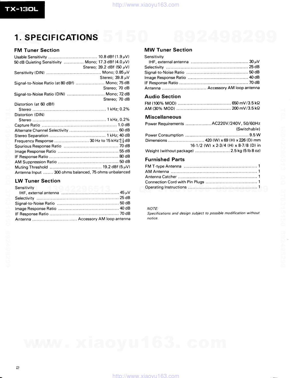
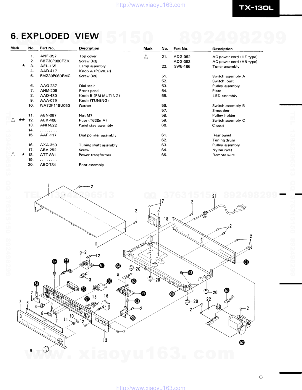
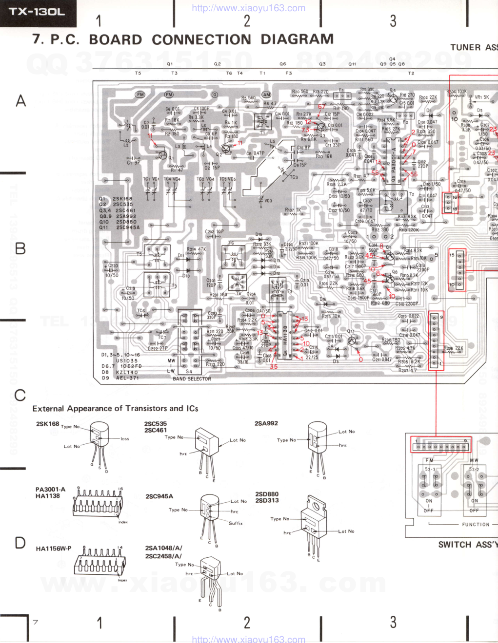
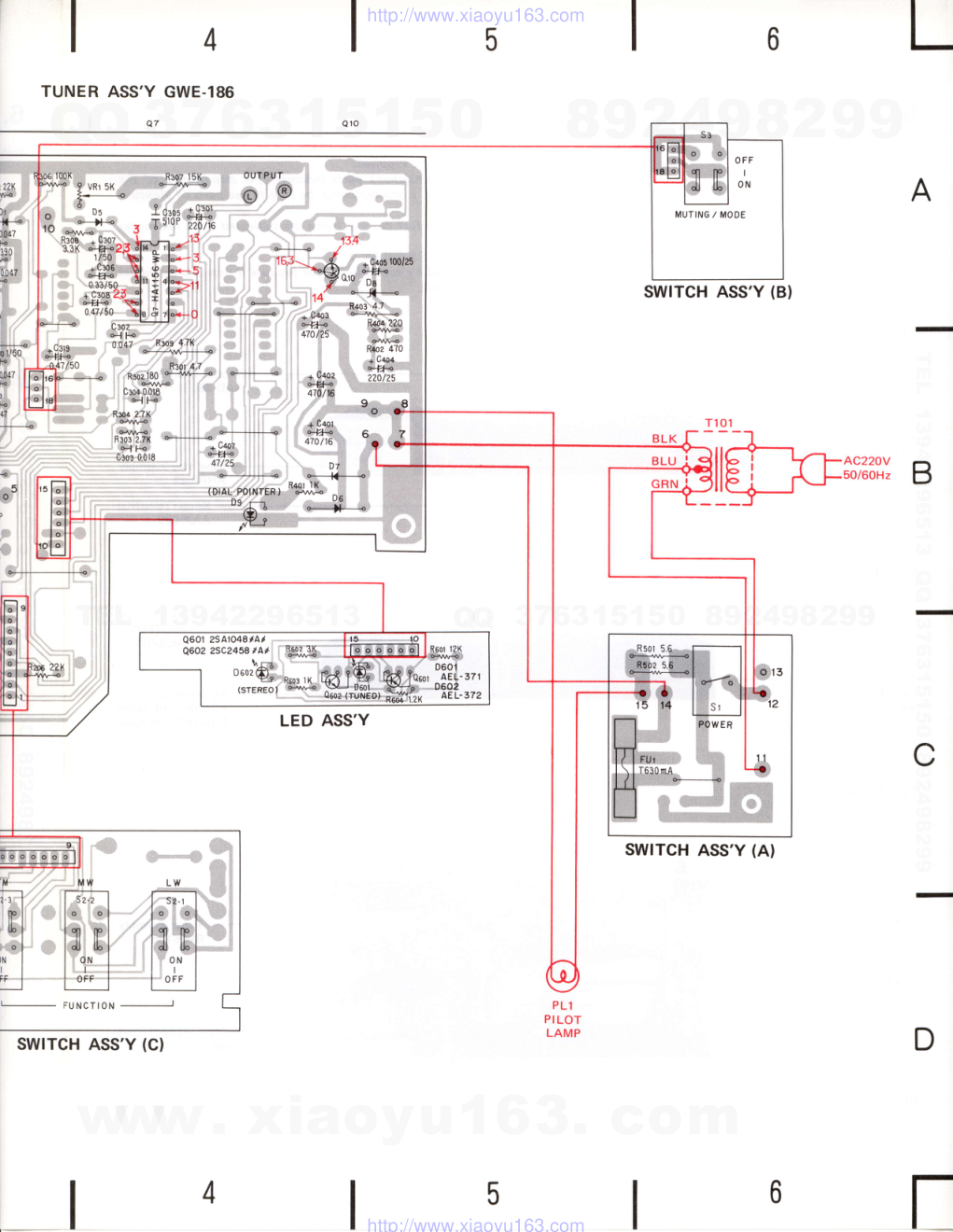
GD rrloNeErl' ORDER NO. ARP -099-O STEREO TUNER TXIISOL o This service manual is applicable to the HE, HB types. o Ce manuel d'instruction se refCre au mode de r6glage, en francais. o Este manual de servicio trata del m6todo de ajuste escrito en espafiol. CONTENTS 1. SPECIFICATIONS . 2. FRONT PANEL FACILITIES 3. BLOCK DIAGRAM 4. C!RCUIT DESCRIPTIONS. . . 5. PARTS LOCATION 6. EXPLODED VIEW . 7. P.C. BOARD CONNECTION DIAGRAM 8. SCHEMATIC DIAGRAM 9. ELECTRICAL PARTS LIST. . 10. PACKING 1 1 . D I A L C O R D S T R I N G I N G 12. ADJUSTMENTS nEcuce AJUSTE 2 3 4 4 5 6 7 9 1 1 1 2 1 3 1 4 1 6 1 8 Change of Line Voltage Line voltage can be changed with following steps. 1. Disconnect the AC power cord. 2. Remove the Top cover. 3. Change the connection wire (for power trans- former) of terminal No. 12 and terminal No. 11 of Switch assembly A as follows: Voltage Terminal No. 12 Terminal No. 11 220V Green wire Blue wire 240V Blue wire Green wire 4. Stick the line voltage label on the rear panel. Part No. Description AAX-193 AAX.192 MODEL TX-130L COMES IN TWO VERSIONS DISTINGUISHED AS FOLLOWS: Type Voltago Remarks H E 22OY and24OV Europe model H B 22OY and24OV U.K. model 22OY label 240V label PICINEEFI ELECTFICINIC CCIFIPCIFIATIGIN 4-1, Mesuno 1-chome, Mesuno-ku, Tokyo.158, Japan PICINEEFI ELECTFICINICE| IUAAI tNC. 1925 E. Dominguez St., Long Beach, Califonnie 9OE1O U.S.A. PIoNEEFI ELEcrFloNlc IEIJFIoPEI N.v. Luirhagen-Haven 9, ao3o Anrwenp, E}etgium P|ONEEFI ELECTFICINIC€i AIJCITFIALIA PTY. LtE. 17AJ184 Boundany Fload, BnaLside, Victonia 3195, Ausrnatia YL o APR. i982 Printed in lapan www. xiaoyu163. com QQ 376315150 9 9 2 8 9 4 2 9 8 TEL 13942296513 9 9 2 8 9 4 2 9 8 0 5 1 5 1 3 6 7 3 Q Q TEL 13942296513 QQ 376315150 892498299 TEL 13942296513 QQ 376315150 892498299 http://www.xiaoyu163.com 1. SPECIFICATIONS FM Tuner Section U s a b l e s e n s i t i v i t y . . . . . . . . . . . . . . . . 1 0 . 8 d B f ( 1 . 9 p V ) 50 dB Quieting Sensitivity Mono; 17.3 dBf (4.0 pV) Stereo; 39.2 dBf (50 pV) S en s i t i vit y (DlN) . . . . . . . . . Mono; 0.8 5 p r V Stereo; 39.8 pV Signal-to-Noise Ratio (at 80 dBf ) .. Mono; 75 dB Stereo; 70 dB S i gn a l -to -No ise Ra t io (Dl N) ......... Mono;72 d 8 Stereo; 70 dB Distortion (at 60 dBf) S t e r e o . . . . . . . . . . . . . . . 1 k { 2 ; Q . 2 o / o Distortion (DlN) S t e r e o . . . . . . . . . . . . . . . 1 k H z , 0 . 2 o / o C a p t u r e R a t i o . . . . . . . . . . . . . . . . 1 . 0 d B A l t e rn a t e Ch a n n e l S e le c tivity ................ 60 d B S t e re o S e o a ra t io n . . . . . . . ..... ......... 1 kHz; zl 0 d B Frequency Response ...... 30 Hz to 1 5 kHz:! fr dB S pu ri ou s Re sp o n se Ra t io ......... ........... 70 d B l m a g e Re sp o n se Ra t io ......5 5 d B l F R e s o o n s e R a t i o . . . . . . . . . . . . 8 0 d 8 AM Suppression Ratio ...... 50 dB Muting Threshold 19.2 dBf (5 pV) Antenna Input ....... 300 ohms balanced, 75 ohms unbalanced LW Tuner Section Sensitivity l H F , e xt e rn a l a n t e n n a ....45 p V Selectivity ... 25 dB S i g n a l - t o -No ise Ra t io .......50 d B lmage Response Ratio ...... 40 dB l F R es po n se Ra t io . . . . . . . ... .. 7 0 d B Antenna Accessory AM looP antenna MW Tuner Section Sensitivity lHF, external antenna ....30pV Selectivity ...25d8 Signal-to-Noise Ratio ....... 50 dB lmage Response Ratio ...... 40 dB l F R e s p o n s e R a t i o . . . . . . . . . . . . 7 0 d B Antenna Accessory AM looP antenna Audio Section FM (100% MOD) ......... 650 mV/3.5 ka AM (30% MOD) ......... 200 mV/3.5 ka Miscellaneous Power Requirements AC22OV l24OV, 50/60H2 {Switchable) Power Consumption ........9.5W Dimensions .......42O (W) x 69 lHl x?26 (D) mm 16-1/2 (W) x2-3/4 (H) x 8-718 (D) in Weight (without package) . .. .. . 2.5 kg (5 lb 8 oz) Furnished Parts F M T - t y p e A n t e n n a . . . . .. . . . . . . . . . ' l A M A n t e n n a . . . . . . . . . . . . . . . . . . . . . . . . 1 A n t e n n a C a t c h e r . . . . . . . . . . . . . . . . . . . 1 C o n n e c t i o n C o r d w i t h P i n P l u g s . . . . . . . .. . . . . . . . . . 1 O p e r a t i n g I n s t r u c t i o n s . . .. . . . . . . . . 1 NOTE: Specifications and design subiect to possible modification without notrce. www. xiaoyu163. com QQ 376315150 9 9 2 8 9 4 2 9 8 TEL 13942296513 9 9 2 8 9 4 2 9 8 0 5 1 5 1 3 6 7 3 Q Q TEL 13942296513 QQ 376315150 892498299 TEL 13942296513 QQ 376315150 892498299 http://www.xiaoyu163.com 2. FRONT PANEL FACILITIES -ilF * *r"_a'';- , - H K cfl _fr...,.t | {=; I @ O poweR swrrcH (PowER) When this switch is set to the ON position, power is supplied to the tuner's main circuits. The unit's power switch is geared to selecting the transformer's secondary and so even at the STAND-BY position, the unit's circuitry will work as long as the power cord is connected to the power outlet. Disconnect the power cord from the AC power outlet when the unit is not in regular use. @ rururruc rNDrcAToR (TUNTNG) This indicates that an FM, MW or LW broadcasting station is being received. @ sreneo tNDtcAToR (srEREo) This lights automatically when an FM program is being broadcast in stereo. It does not light when the FM MUTING switch has been set to the OFF/MONO Position. @ rru MUTTNG swtrcH (FM MUTING) In the released position when it is normally set, this switch suppresses the annoying interstation noise which is heard when tuning in FM broadcasting stations. lf the station signals are weak and there is a great deal of noise and distortion, depress this switch (and monaural sound reproduction results). This switch does not work with MW and LW reception. @ rurutruc KNoB Rotate this knob to pick up the stations (FM, MW or LW) @ rurucfloN swlTcHEs (FM, MW or LW) Depress the FM switch for listening to FM broadcasts. Depress the MW switch for listening to MW broadcasts. Depress the LW switch for listening to LW broadcasts. @ rneouENcY scALE This indicates the frequency of the broadcasting station (FM, MW and LW). The top level figures (88-1081 indicate the FM frequencies. The center level figures (55ru160) indicate the MW frequen- cies. The bottom level f igures ( 150-350) indicate the LW f requen- cies. @ ourPUT coRD (accessory) This is used to hook the unit up with the stereo amplifier. @ r-rYPE FM ANTENNA (accessory) This antenna is for listening to FM stations and it should be connected to the rear panel of the unit. This is a spare antenna for listening to FM stations and is used until an outdoor FM antenna is erected. For the best reception, an outdoor antenna should be obtained. @ nnn ANTENNA AND ANTENNA cATcHER (accessory) This antenna is for listening to MW and LW stations and it should be connected to the rear panel of the unit. The anten- na catcher is used when fixing the antenna to a wall or other location. NOTE: Even with the accessory T-type FM antenna and AM antenna it may be impossible to tune into some stations when the broad- cast stations are too far awaY or when the unit is located in a weak-signal area such as in the mountains. ln cases like this, use an external antenna. 3 www. xiaoyu163. com QQ 376315150 9 9 2 8 9 4 2 9 8 TEL 13942296513 9 9 2 8 9 4 2 9 8 0 5 1 5 1 3 6 7 3 Q Q TEL 13942296513 QQ 376315150 892498299 TEL 13942296513 QQ 376315150 892498299 http://www.xiaoyu163.com 3. BLOCK DIAGRAM A N T E N N A FM 300f] 7 5 rI G ND F M F R O N T - E N D A M T U N E R IN DICAT ORS S T E R E O FM IF AMP 8 DET ECT OR I C ( P A 3 0 0 t - A ) FM MPX STEREO DEMODULATOR r c ( H A l r 5 6 w ) I C ( H A i l 3 8 ) D I A L POINTER POWER SUPPLY ILLUMINATION 4. CIRCUIT DESCRIPTIONS FM Tuner The FM front end is comprized of a J-FET (2SK168) single-stage RF amplifier, and NPN transistor mixer, and an NPN transistor modified Clapp local oscillator. The IF stage consists of. 2 dual-element ceramic filters, a single transistor amplifier element, and IF system IC (PA3001-A) which incorporates the IF limiter amplifier, FM detector, ffid the FM muting circuit. FM Multiplex Stereo Decoder The stereo decoder stage employs an FM MPX IC (HA1L56W-P), while the subcarrier signals (frequencies above 19kHz) are removed by an - 18dB/oct. active filter consisting of a PNP tran- sistor. This active filter also serves as an amplifier for frequencies within its passband, and eliminates crosstalk. AM Tuner The AM tuner is two wave-band tuner $rith LW (150kHz-350kHz) and MW (525kHz-1605kH2). This employs a 2-ganged tuning capacitor, a single element ceramic filter, and an IC (HA1138) consisting of an RF amplifier, mixer, 2-stage IF amplifier, detector and AGC circuit. www. xiaoyu163. com QQ 376315150 9 9 2 8 9 4 2 9 8 TEL 13942296513 9 9 2 8 9 4 2 9 8 0 5 1 5 1 3 6 7 3 Q Q TEL 13942296513 QQ 376315150 892498299 TEL 13942296513 QQ 376315150 892498299 http://www.xiaoyu163.com 5. PARTS LOCATION Front Panel View Top cover ANE-357 Knob A (POWER) AAD417 Front panel ANM-208 Rear Panel View Terminal 4P (ANTENNA) AKA.O18 Top View NO?ES; o Parts without part number cannot be supplied. c The I marh found on some component parts indicates the importance of the safety factor of the part. Therefore, when replacing, be sure to use parts of identical designation. o For your Parts Stoch Control, the fast moving items are indicated with the marhs ** and *. ** GENERALLY MOVES FASTER THAN *. This classification shall be adjusted by each distributor because it depends on model number, temperature, humidity, e tc. Knob B (FM MUTING) AAD48O @@GA t-i- Panel stay assembly ANR.522 Knob (TUNINGI AAA.O79 Terminal 2P (OUTPUT} AKB.O77 AC power cord ADG-062 (HE typsl ADG-063 (HB typel Tuner assembly GWE-186 ** Push switch (FUNCTION) ASX-190 Tuning shaft asembly AXA-35O a* A** Power transformer ATT.881 Push switch (POWER) ASG-s16 Push switch ( ASG-313 www. xiaoyu163. com QQ 376315150 9 9 2 8 9 4 2 9 8 TEL 13942296513 9 9 2 8 9 4 2 9 8 0 5 1 5 1 3 6 7 3 Q Q TEL 13942296513 QQ 376315150 892498299 TEL 13942296513 QQ 376315150 892498299 http://www.xiaoyu163.com 6. EXPLODED VIEW Mark No. Part No. Description 1. AN E-357 2. BBZ30P080FZK * 3 . A E L - 1 6 5 4. AAD417 5. PMZ30P060FMC AAG-237 ANM.208 AAD.48O AAA-O79 wA73F1 18U050 ABN-067 AEK4O6 ANR-522 A A F - 1 1 7 Mark No. Part No. Description b . 7 . 8. 9. 1 0 . Top cover Screw 3x8 Lamp assembly Knob A (POWER) Screw 3x6 Dial scale Front panel K n o b B ( F M M U T I N G ) K n o b ( T U N I N G ) Washer N u t M 7 Fuse (T630mA) Panel stay assembly Dial pointer assembly Tuning shaft assembly Screw Power transformer Foot assembly A 21. ADG-062 ADG-063 22. GwE-186 5 1 . 52. 53. 54. 55. AC power cord (HE typel AC power cord (HB type) Tuner assembly Switch assembly A Switch joint Pulley assembly Plate LED assembly Switch assembly B Smoother Pulley holder Switch assembly C Chassis Rear panel Tuning drum Pulley assembly Nylon rivet Remote wire 1 1 . A ** 12. 1 3 . 14. 1 5 . 56. 57. 58. 59. 60. - - A 16. AXA-350 17. ABA-252 18. ATT-881 1 9 . 20. AEC-784 6 1 . 62. 63. 64. 65. 2 1 )4=:\, fy M \r'" z@ o sJ?.- 5 x r / e-{t -'v-z - www. xiaoyu163. com QQ 376315150 9 9 2 8 9 4 2 9 8 TEL 13942296513 9 9 2 8 9 4 2 9 8 0 5 1 5 1 3 6 7 3 Q Q TEL 13942296513 QQ 376315150 892498299 TEL 13942296513 QQ 376315150 892498299 http://www.xiaoyu163.com 3 2 TUNER A 7. P.C. BOARD CONNECTION DIAGRAM Q4 Q 9 Q 5 a 8 @ @ @ R.560 @ ItrP'JtrE F+;t flk o #"tg30 n,,zzx * Re 4r H o* .-*lqtzx al c'l oot w csool c: l00P o# bI RE t80 *-J-8 390 6 o--r''< Dt " "*r ,,?,f' "lPl t=."1 cJojl tlll "/ ggt -' cEE ^ ""'F1 -ri- "rr + ilfi l{ ffi EEI '"1'+,,,]1i1 I ss 'str '-;r *i:- --;1'*rrii.* ITE xru, --.,,- ffi#'*'' ;&.'ryI#; y.- r\' :;l :** 9'u0,, ^1. /- nitTfi"u'"-,r-- mtA" r's Bo,'u t"--:'i,qt"-€fiH:' #;"' rd*+,%Ti 1103 390 ^ Crm 0.047 u o--{ }4 7 crooT 0 047. -L ctl? ?iE ilH' ( y.))i'u' ;"{"X l{ -i:ir' - - - B R2ls lox Cztz 0X22 o{ f4 D9 A'EL;T?1.. '' BANO SELECTOR External Appearance of Transistors and lCs 2SK168 Typ. No Lot No PA3q)1-A HAl 138 HAl 1s6W-P 2SC535 2SA992 ross '*otlro.*"-S--r",*" ,rr"-.-{#l:::-" ^,. ---Lnfl )fril^- ; !\ g u\ 2SC945A zSD880 2SD313 Tvpe 2SA104A|AI 2SC2458lAl Type No- hre- tr,l l l r r P l lr ul l o o l l''' I l o F F I F U N C T I O N - SWITCH ASS' 3 '"'"*.,r*,',fu,.^.y^ri^.." _( fr:' * #,$:l"li+r. . e, *, 'l+ '[L'fi't1 V''- ";ffi'ffi.ffii't ii3?iiiil L+ ' 3#1 ''#: ffi |4J*"lfi'[ c R30 R3 rl Ca ,'/\,F 9vRr5K *-- ^ U 5 :^ e- tf- tlSi *Wz 1/50 \ + cao6 t-+)4 0.33/50 + C:oa 2J o+)4 \ 0.4?/50 Cao o{ F .c319 0 04 *)4 -A47150 ,!l*']l " o *,.,nfl"i;S 5;:l .lV'- erFo + 44" ll, oll i,.,,zz.o ii"i-11.'3{"\l i.l7 @--or ^ e,r ^i]l: rt; l[ J| :m _nffi:-x'-".1.*l',l l*s-ts .3Jig d tHgf*"*"* d5* lru ql m 'ffi; i;*'tP st i l'-10" " ilLq o''u-J;t:tl' ilTl;;ii;,?^ 4# isr#kJ*# #\;,6ffi 3:'t*;li.t;" ,-'n lt."tl n.gle.- -* $'5 t#t'* Q8'9 2SA992 o-l Fo Rre 8.2K 0.047 ero ?sogao c1osoo47 # _ Qtr asce4sa c,o,:;..-.---- D15 :d .Ts{^Til5i* *i F _ + t s i 3 : l o 0 2 '--r-E- ^Tffi tilit.ff'i'^ .n' ? SSiisg' "tui4e*s2a- "l H I rr#q'- l$l ]ffi,,t-""'^ffi* ffi o,ruwq+--qffiRo*,0K 6s :gT ffiil [_,-1 rl =||--- ,,0,1 FEI *B ?^ ffif* n.?t6d '".8.rrqu*,'o.rx' I L-r!,r l-- :;1"1 ; | -.F" I ll+,1 | +Xfii Rro6 2zK *-45Pdi*R31i t2K # lFql" 'mry.* m,,n"'y*ffi,',ffi.ff '. . o ol G|+{ ffstz 6Eo 636 2299P o E o I o o o o -l' www. xiaoyu163. com QQ 376315150 9 9 2 8 9 4 2 9 8 TEL 13942296513 9 9 2 8 9 4 2 9 8 0 5 1 5 1 3 6 7 3 Q Q TEL 13942296513 QQ 376315150 892498299 TEL 13942296513 QQ 376315150 892498299 http://www.xiaoyu163.com 6 5 TUNER ASS'Y GWE-186 Q 7 A swtTcH Ass'Y (B) SWITCH ASS'Y (A) B C F U N C T I O N SWITCH ASS'Y (C) D 6 5 4 MUTING / MOOE Q60r 2SArO4srAr Q602 25C2458 tAt www. xiaoyu163. com QQ 376315150 9 9 2 8 9 4 2 9 8 TEL 13942296513 9 9 2 8 9 4 2 9 8 0 5 1 5 1 3 6 7 3 Q Q TEL 13942296513 QQ 376315150 892498299 TEL 13942296513 QQ 376315150 892498299 http://www.xiaoyu163.com 3 2 Q i - 3 FI\4 FRONT- END c y g L c z E lf t Tr5p E v c z I 'l ",I o2 H#K Q 4 2 S C 4 6 i FIV IF AMP s 2 ' 2 Q5 PA c|2 - 22Oc - - - 54: aAND SELECTOR a s x - t 5 3 T 3 V G r A C X - O 2 7 T C 3 : A C t - O O 6 T C 6 , 7 : A C t - O t 5 n6 4.7 I l o . o l Rt2 ,:),ittl cr5 o.ol 4 6 { PILOT LAMP 8V O3A A E L . t 5 5 c t 4 o.ol I Q 3 I 2 S C 2.2' R203 3.3k R40l uu ?20/ 2 3 {OIAL POINTER) D9 AEL-372 D8 K Z L t 4 0 !;-,ffi v n l : V C O A D J a c P - o 9 | c405 25 D 9 I I s t : P o w E R A S X - r 9 0 oil r+i-l ac2zov_-f)l i g ll soraowt--j ; g ll a L--,I,__9 ll I asc-rre d\sr L_ __ __ i cFil f,\ 1630nA 4 A E K _ 4 0 6 oqt d AC rcWER CORO A o G - O 6 2 - - - - J s 2 - l SWITCH Ass'y (A) | - - S W I T C H A s s ' y ( C ) 3 2 8. SCHEMATIC DIAGRAM T U N E R A s s ' y G W E - 1 8 6 _-_ 75n A Qi 2SKI6A q2 2SC535 FM UNBAL,V---------t L3 14 fC2 300l) 9AL. FM l-- 75O UNBAL. L..-.__ AM LOOP ANT. L :Rr9 390 cr6 -{F-r ao22 D D I ust035 Q i r 2 s c 9 4 5 A I\,I U IING US'fO35 Lto/3o ? - - r I L - - - - - - - i |ift+ +3fl. Q 6 H A i t 3 A A M T U N E R DIO r l5 usro3 3 Q 7 H A f i 5 6 W - P MPX IC D5 USiO35 qro zsDaao REGU LATOR ---{A}- | -- Rs - +b:4?o/ 5Et I 5oo L5 | CIO aP '__?-F_T-JF F /r ,f T,c: # e v ./'vc3 lrcs + Rro RzOl tao C2O4 o.ol www. xiaoyu163. com QQ 376315150 9 9 2 8 9 4 2 9 8 TEL 13942296513 9 9 2 8 9 4 2 9 8 0 5 1 5 1 3 6 7 3 Q Q TEL 13942296513 QQ 376315150 892498299 TEL 13942296513 QQ 376315150 892498299 http://www.xiaoyu163.com 6 5 4 cr2 - l 22Oo Q 5 P A 3 O O I - A FIII IF AIUP A DET L t : a l c - t 5 7 L 2 : A T C - r 5 6 L 3 : A I C - r 5 9 t 4 | a T c - t 5 8 L 5 : A T C - r 6 0 L 6 I A T H . O 4 9 LED Ass'y ;;,l_l A T E - O 5 3 A T E . O 3 2 A T 8 - 0 7 8 a T 8 - O a 2 T 6 | ^ T D - O O 5 F t t 2 . A f F - 1 2 6 F 3 : A T F - l 2 l NOTE: The indicated semiconductors are representatiue ones only. Other alternative semiconductors may be used and are listed in the parts list. 1. RESTSTORS: Indiclt€d in O, 7.W, rS% toler.me unl6 othcilis notad k : ke, M : M n , ( F ) : ! l % , ( G ) : 1 2 X , ( K l : 1 1 0 9 6 , { M ) : r 2 0 % r o t € r . @ 2. CAPACITORS: Indicated in Gpaciiy (! F)/voltag€ (V) unl6 othceis not6d p : pF Indication without voltage is SoV except elctrolytic csp&itor. 3, VOLTAGE f- | DC vohage (V) 6t no input signal @:signat vottage at FM itooHz 75kH: DEV. 4. OTH€RSl A : Adjusting Fint. The I mark f@nd on sme componenr p6ns indicatG the ih. pon.nce of the sfety lactor ot the pen. Thercfore, when rcplacing, be src to ue pani of identical dsignation. This is the basic $hematic diagram, but the eruat circuit may vary due to improvements in d6ign. swtTcHES: Sl : POWER oN - .g!L S2-l : FUNCTION LW ON - gIE S2-2: FUNCIION MW ON - OFF S2-3: FUNCTION FM ON - OFF 53 : MUTING ,/ MODE ON/AUTO - OFF,/MoNo 54 : BANO SELECTOR LW - MW The underlinod irdi6t6lhe ilitch @sition. I OUTPUT l l - 5 o d l J - F t/5o - I - vnr: VCO ADJ a c P - o 9 l R r ! I I o o I oFF I _) s 2 - 3 F T 6 5 4 f2 a.2l r - - - - - - 1 i - l I *.'c 'oz -*!'^o.a- 't' T1rlto I vv-' "' FilO 2201 :T':jr POWER SUPPLY CIRCUIT FOR HB TYPE L GWE-t 86 ac 240v 50 /60 Ar AC POWER CORO A D G ' O 6 3 www. xiaoyu163. com QQ 376315150 9 9 2 8 9 4 2 9 8 TEL 13942296513 9 9 2 8 9 4 2 9 8 0 5 1 5 1 3 6 7 3 Q Q TEL 13942296513 QQ 376315150 892498299 TEL 13942296513 QQ 376315150 892498299 http://www.xiaoyu163.com 9. ELECTRICAL PARTS LIST NO?ES: c When ordering resisfors, first conuert resistance ualues into code form as shown in the following examples. Ex. I When there are 2 effective digits (any digit apart from 0), such as 560 ohm and 47h ohm (tolerance is shown by J = 57o, and K: 107.). 5 6 0 a 5 6 x 1 0 ' 5 6 1 . . . . R D % P S t s s ] D / 4 7 h e 4 7 x 1 0 3 4 7 3 . . . . R D % P S @ A A J 0.5a 0R5 . . RN2H @Etrr I a 0 1 O . . . R s r P @ t r o r Ex. 2 When there are 3 effectiue digits (such as in high precision metal film resis- tors). - 5 . 6 2 h n s 6 2 x 1 0 0 s 6 2 1 . . . . R N v 4 s R E G A m r t The A marh found on some component parts indicates the importance of the safety factor of the part. Therefore, when replacing, be sure to use parts of identical designation. o For your Parts Stock Control, the fast mouing items are indicated with the marhs ** and *. ** GENERALLY MOVES FASTER THAN *. This classification shall be adjusted by each distributor because it depends on model number , temperature, humidity, etc. GWE-186 A * ATr-8gl _ r A ADG_062 A ADG-063 * AEL-165 PLI Lamp assembly A ** AEK-406 FU1 Fuse (T630mA) Mark Part No. Symbol & Description cKDYF 473250 C101, C103-C106, C108, C111, cl13, C216, C302,C211 cKDYF 223250 C16, C215 cEA471M 16L C401.C402 0EA471M25L C403 0EA221M25L C404 cEA R33M 50L C306 cEA R47M 50L C206, C308, C316, C318, C319 cEA 010M 50L C110. C307 cEA 100M 50L C102,C219,C220,C223,C309, cl09 OEA220M25L C214 cEA 330M 16L C209 cEA 470M 10L C107. C205 cEA 470M 25L C407 cEA 101M 25L C405 cEA 221M 16L C301 cEA 2R2M 50L C224 cosA 331K 50 C203 cosA 51 lJ 50 C305 cosA 121K 50 C201 RESISTORS Note: When ordering resistors, conuert the resistance ualue into code form, and then rewrite the part no. as before Mark Part No. Symbol & Description * ACP-Og1 VRI Semifixed (5k) RN7.PO 1502F R307 RD%PM !trtrJ R2, R6, R12,F.14, R101, R207, R301, R403 R D l / 8 P M O O D J F t 1 , R 3 - R 5 , R 7 _ R 1 1 , 8 1 3 , R 1 5 - R20, Rl02-R1 13, R201-R206, R208, R210-R215, R302-R306, R 3 0 8 - R 3 1 2. R 3 1 4 - R 3 2 1 , R 4 0 1 , R402. R404 Miscellaneous Parts Mark Part No. Symbol & Description Tuner assembly T101 Power transf ormer Tuner Assembly (GWE-186) CAPACITORS Mark Part No. AC power cord (HE type) AC power cord (HB type) Symbol & Description - ACK-027 VC Tuning capacitor ACM-006 TC3 Ceramic trimmer ACM-015 TC6.TC7 Ceramic trimmer cGB R47K 500 C8 ccDcH 080D 50 c10 ccDRH 1soJ s0 c9 ccDTH 100D 50 C202 ccDcH 't 50J 50 c12 ccDUJ 090D 50 Cl ccDUJ 1s0J 50 C2 ccDsH 270J50 C222 ccDcH 330J 50 Cl 1 ccDs|- 060D 50 c3 ccDSL 101J 50 C5 ccDSL 221J50 C112,C207 CKDYB 561K 50 C3't 1. C314 CKDYB 182K 50 C315, C317 CKDYB 222K50 C310. C313 CKDYX 183M 25 C303, C304 cKDYF 1032 50 C4, C6, C7, C13-C15,C204, c204, c210, c212, c213 - www. xiaoyu163. com QQ 376315150 9 9 2 8 9 4 2 9 8 TEL 13942296513 9 9 2 8 9 4 2 9 8 0 5 1 5 1 3 6 7 3 Q Q TEL 13942296513 QQ 376315150 892498299 TEL 13942296513 QQ 376315150 892498299 http://www.xiaoyu163.com SEMICONDUCTORS Mark Part No. Symbol & Description Switch Assembly C Mark Part No. Symbol & Description ** ** ** ** ** ** ** ** ** ** * * * A 25K1 68 2SC535 2SC461 PA3001-A HA1156W.P H A 1 1 3 8 2SA992 2SC945A 2SC880 (2SD313) us1035 ( 1 52473 ) (1 Sl 555) 1 OE2FD KZL140 AE L-372 o1 02 03, 04 o5 Q7 o6 08, 09 01 1 0 1 0 D1, D3-D5, D10-D16 D6, D7 D8 D9 LED Symbol & Description ** Asx-190 LED Assembly Mark Part No. Remote push switch (FUNCTION) Symbol & Description T5 LW ANT coil TG LW OSC coil F1, F2 FM ceramic f ilter F3 AM ceramic filter Symbol & Description ** 2SA1048/A/ 0601 ** 2SC2458lAl 0602 * AEL.371 D6O1 LED * AEL-372 D6O2 LED RDl/8PM BODJ R6O1 -R6O4 1O. PACKING r---qh 2---S Mark No. Part No. Description 't. AT8-076 2. ADH-Oo4 3. ADE-015 4. ARE-O33 AR8-486 5. AHA-296 6. AHA-297 7. AHE-O42 Antenna assembly T-type FM antenna Cord Operating instructions (HEl ( English/German/French/ Italian ) Operating instructions (HB ) (English) Front pad Rear pad Packing case COILS. FILTERS Mark Part No. ATC-157 ATC-156 ATC-159 ATC-158 ATC-160 ATH-049 ATE-053 ATE-052 ATB.O78 ATB.O82 ATD.O11 ATD-006 ATF.126 ATF.121 (ATF-133) OTHERS Mark Part No. L1 L2 L3 L4 L5 L6 T1 T2 T3 T4 FM ANT coil FM ANT coil RF coil RF coil FM OSC coil RF choke coil FM lF transformer FM det. transformer AM ANT coil AM OSC coil AKA.O18 AKB-077 ** ASX-I53 Switch Assembly A Mark Part No. 4P terminal (ANTENNA) 2P terminal (OUTPUT) 54 Remote slide switch Symbol & Description 51 Push switch (POWER) R501, R502 A ** Asc-s16 RD%PM 5R6J Switch Assembly B Mark Part No. Symbol & Description ** ASG-313 53 Push switch (FM MUTING) www. xiaoyu163. com QQ 376315150 9 9 2 8 9 4 2 9 8 TEL 13942296513 9 9 2 8 9 4 2 9 8 0 5 1 5 1 3 6 7 3 Q Q TEL 13942296513 QQ 376315150 892498299 TEL 13942296513 QQ 376315150 892498299 http://www.xiaoyu163.com 11. DIAL CORD STRINGING 1. Remove the top cover. 2. Remove the tuning drum from the shaft of the tuning capacitor. 3. Tie one end of the cord to the stud A located inside the tuning drum. 4. Rotate the tuning capacitor right around until the rotor blades are fully intermeshed. 5. Secure the tuning drum back onto the tuning capacitor shaft, making sure that the securing screw faces directly upward. 6. Pass the cord out through the small opening in the circumference of the tuning drum (see diagram), and then take it over pulleys B and C in that sequence. 7. Wind the cord around the tuning shaft 3 times. 8. Pass it over pulley D, wind it around the tuning drum 2 times, and finally tie it to the spring hook F so that it is tensioned. Starting point IIt trM | | | | I I I I N,4\n/ I 9. Turn the tuning shaft, and check that the cord moves smoothly. 10. Cut off any excess cord. 11. Turn the tuning shaft counter-clockwise as far as it will go. 12. Align the dial pointer with the starting point of the dial scale, and then pass the cord over it. 13. Check that the dial pointer is in line with the starting point of the dial scale. 14. Finally apply the locking paint to the cord securing positions (stud A and spring hook F) and the dial pointer connection. Dial pointer Tuning drum Spring hook Tuning shaft \-----"- \ www. xiaoyu163. com QQ 376315150 9 9 2 8 9 4 2 9 8 TEL 13942296513 9 9 2 8 9 4 2 9 8 0 5 1 5 1 3 6 7 3 Q Q TEL 13942296513 QQ 376315150 892498299 TEL 13942296513 QQ 376315150 892498299 http://www.xiaoyu163.com 12. ADJUSTMENTS FM Tuner Section o Check that the dial pointer indicates a starting point. o Connect the SIGNAL meter between terminal no. 5 of tuner ass'y and the ground. o connect the TUNING meter between terminals no. 1 and no. 2 of tuner ass'y. o Set the FM switch to ON and the FM MUTING switch to OFF. NOTE: Connect the MPX SG to the FM SG external modulator terminal and set the modulation to Main (IhHz, L+R) +67.5hH2 deuiation, Pilot (19hHz) !7.ShHz deuiation. AM Tuner Section o Check that the dial pointer indicates a starting point. o Turn ON the MW switch. o Connect the SIGNAL meter between the terminal no. 5 of tuner ass'y and the ground. Position of I Adlurt-"nt otat potnler I point -l Ser the TUNING meter to the center position and the SIGNAL VC3 | meter to the maximum value. ( F i g . 1 2 - 1 ) Repeat steps 1 to 2. Set the SIGNAL meter to the maximum value. Set the TUNING meter to the center Dosition. Turn ON the FM MUTING switch. Remove R lO4 when muting operation stops above 30dB. Set the signal of the terminal no. 10 to l9kHz (1100H2). Minimize the distortion of the OUTPUT terminal signal. Step AM 3Q"/o SG modulationl Position of dial pointer Adiustment point Adlustment procedure Frequenry Level I 1400kHz 1 00dB l4OOkHz TC5 Set the output of the OUTPUT terminal to the maximum value. 2 600kHz 1 00dB 600kHz T4 J Repeat steps 1 to 2 4 r4ook;; T .*r f ''ooons.-f--ica 5 6ookHz I soae I ooor.H. l t. o Repeat steps 4 to 5. www. xiaoyu163. com QQ 376315150 9 9 2 8 9 4 2 9 8 TEL 13942296513 9 9 2 8 9 4 2 9 8 0 5 1 5 1 3 6 7 3 Q Q TEL 13942296513 QQ 376315150 892498299 TEL 13942296513 QQ 376315150 892498299 http://www.xiaoyu163.com Long Wave Section . Set the AM BAND switch to the LW position. Step AM SG (4O0Hz, 30% modulation) Position of dial pointer Adjustment point Adiustment procedure Frequenry Level 1 340kHz 100d8 34OkHz TC6 Adjust until demodulated signal at OUTPUT terminal is maximum. 2 16OkHz 1 00dB 160kHz T5 3 Set the AM SG to 30dB output level, repeat steps 1 to 2 above. 4 340kHz 50dB 340kHz TC7 Adjust until demodulated signal at OUTPUT terminal is maximum. 5 160kHz 50dB l6OkHz T6 6 Repeat steps 4 to 5 until maximum sensitivity is attained. Stator Rotor blade Stator Rotor blade Spatu la (GGK-066) qT-p fifi[ X ffi X Fig. 12-1 Adjustment of tuning capacitor c vRl-.G no. 1O----e #,,1EX @ f,"u Tl3 Tc7 no. 2---{ e--no. 1 fl"--"'u HI ql Fig. 12-2 Adjustment points 1 5 www. xiaoyu163. com QQ 376315150 9 9 2 8 9 4 2 9 8 TEL 13942296513 9 9 2 8 9 4 2 9 8 0 5 1 5 1 3 6 7 3 Q Q TEL 13942296513 QQ 376315150 892498299 TEL 13942296513 QQ 376315150 892498299 http://www.xiaoyu163.com 12. REGLAGE Section tuner FM . V6rifier que I'aiguille se trouve sur la position de d6part. r Brancher le S-mdtre (SIGNAL) entre la borne no 5 du tuner et la masse. o Brancher I'indicateur d'accord (TUNING) entre la bome no 1 et la borne no 2 du tuner. o D6placer I'intermpteur FM sur Ia position ON, et le s6lecteur de r6glage silencieux FM (FM MUTING) sur la position OFF. Etape FM SG (4O0Hz, d6viation t75k Hz) Position de I'aiguille Point de 169lage Proc6dure de r6glage Fr6quence Niveau 1 106MHz 1 06dB 106MHz TC3 D6placer l'indicateur d'accord sur la position centrale et r6gler le S-mdtre (SIGNAL) i sa valeur maximum. 2 90MHz 1 06dB 9OMHz vc3 ( F i g . 1 2 - 1 ) 3 R6pdter les 6tapes 1 et2. 4 98MHz 18dB 98MHz TC1 TCz, T1 Rdgler le S-mdtre (SIGNAL) d sa valeur maximum. 5 Pas de signal Bruit blanc T2 D6placer l'indicateur d'accord sur la position centrale. 6 Ddplacer le s6lecteur de rdglage silencieux FM (FM MUTING) sur la position oN. 7 98MHz 25-35dB Variable 98MHz R 104 Enlever le R1O4 lorsque le 169lage silencieux atteint 30d8. I I 98MHz I aoae N'est pas modu16 98MHz V R 1 R 6 g l e r l e s i g n a l d e l a b o r n e n o 1 0 d 1 9 k H z ( 1 1 0 0 H 2 ) . 9 98MHz I eooe Modulation st616o 98MHz T 1 (entre 190" ) R6gler au minimum la distortion du signal de la borne de sortie (OUTPUT). NOTE: Connecter le MPX SG d lo bome du modubteur extAiear FM SG et ftgler la moduhtion Main (pincipale) Bu une de- oiotion de (lhHz, L+R) !7,5hH2. Section tuner AM o V6rifier que I'aiguille se trouve sur la position de d6part. o D6placer I'intetrupteur MW sur la position ON. r Brancher le S-mdtre (SIGNAL) entre la bome no 5 du tuner et la masse. Etape AM SG (40OHz, modulation de 30%) Position de l'aiguille Point de r69lage Proc6dure de r6glage Fr6quence Niveau 1 14O0kHz 1 00dB 140OkHz TC5 R6gler la sortie de la borne de sortie (OUTPUT) d sa valeur m a x i m u m . 2 600kHz 't00dB 600kHz T4 3 Rdp6ter les dtapes 'l et2. 4 140OkHz 30dB l4OOkHz TC4 5 6OOkHz 30dB 600kHz T3 6 Rdp6ter les 6tapes 4 et 5. www. xiaoyu163. com QQ 376315150 9 9 2 8 9 4 2 9 8 TEL 13942296513 9 9 2 8 9 4 2 9 8 0 5 1 5 1 3 6 7 3 Q Q TEL 13942296513 QQ 376315150 892498299 TEL 13942296513 QQ 376315150 892498299 http://www.xiaoyu163.com Section grandes ondes . D6placer le s6lecteur de gammes d'ondes sur la position LW (grandes ondes). Etape AM SG (4fl)Hz, modulation de 30%l Position de I'aiguille Point de 169lage Proc6dure de r6glage Fr6quence Niveau 1 34OkHz 1 00dB 34OkHz TC6 Rdgler jusqu'i ce que le signal de d6modulation A la borne de sortie (OUTPUT) soit au maximum. 2 16OkHz 100d8 l6OkHz T5 3 R69ler le signal AM (AM SG) a un niveau de sortie de 30d8, puis, r6p6ter les dtapes 1 et 2 ci-dessus. 4 160kHz 50dB 1 60kHz TC7 R6gler jusqu'A ce que le signal d6modul6 d la borne de sortie (OUTPUT) soit au maximum. 5 160kHz 50dB 160kHz T6 6 Rdpdter les 6tapes 4 er 5 jusqu'au point d'intensit6 maximum. Plaque mobil Stator Plaque mobile Fig. 12-1 R6glage du capaciteur de syntonisation Spatule (GGK-066) sffi 4[ru X $m 1flil\ X C v R 1 - G R 1 0 4 no 2-{ t-no 1 fl*"'u HI qJ TC2 TCI Fig. 12-2 Points de r6glage 1 7 www. xiaoyu163. com QQ 376315150 9 9 2 8 9 4 2 9 8 TEL 13942296513 9 9 2 8 9 4 2 9 8 0 5 1 5 1 3 6 7 3 Q Q TEL 13942296513 QQ 376315150 892498299 TEL 13942296513 QQ 376315150 892498299 http://www.xiaoyu163.com 12. AJUSTE Secci6n del sintonizador de FM o Comprobar que el indicador del cuadrante sefrala un punto de inicio. o Conectar el medidor de sefral (SIGNAL) entre el terminal no. 5 del conjunto del sintonizador y tierra. o Conectar el medidor de sintonizaci6n (TUNING) entre los terminales no. 1 y 2 del conjunto aet sinto- nizador. o Poner el selector de FM en la posici6n ON y el interruptor de silenciamiento en FM (FM MUTING) en la posici6n OFF. NOTA: Conectar el generador de sefial de multipkx (MPX SG) al terminal de modulador exterior del generador de sefi.al de FM (FM SG) y ajustar la modulaci6n a Principal (LhHz, Izq.!Der.) t67,5kHz de dewiaci6n. Secci6n del sintonizador de AM o Comprobar que el indicador del cuadrante sefrale un punto de inicio. o Poner en la posici6n ON el selector de MW. o Connectar el medidor de sefral (SIGNAL) entre el terminal no. 5 del conjunto del sintonizador y tierra. Paro FM SG l4filHz, t75kHz de dewiaci6n) Porici6n del indicador del cuadranto Punto de aiu3te Procedimiento d€ aiuste Frecucncia Nivel 1 1O6MHz 106d8 lO6MHz TC3 2 9OMHz 106d8 9OMHz vc3 ( F i g . 1 2 - 1 ) central y el medidor de sefial (SIGNAL) en el valor m6ximo. 3 Repetir los pasos 1 al 2. 4 98MHz 18dB 98MHz T C l , TC2,T1 Alustar el medidor de sefral (SIGNAL) al valor m6ximo. 5 No hay sefial Ruido blanco T2 Poner el medidor de sintonizaci6n (TUNING) en la posici6n central, 6 Poner en la posici6n ON el interruptor de silenciamiento en FM {FM MUTINGI. 7 98MHz 25-3tu8 Variable 98MHz R104 Extraer el R1O4 cuando la operaci6n de silenciamiento se detiene por encima de los 30d8. I eBMHz I asot no modulada 98MHz V R 1 Ajustar la sefial del terminal no. 10 a 19kHz (r100Hz). I 98MHz I 86dB Modulaci6n estereof6nica 98MHz T1 (dentro de t9O" l Minimizar la distorsi6n de la seflal del terminal de salida (OUTPUT}. Paro AM SG {4(XlHz, 3O% de modulaci6nl Polici6n del indicador del cuadrante Punto de aiuJte Procedimiento de aiusto Frccuencia Nivel 1 140OkHz 100d8 l4OOkHz TC5 Ajustar la salida del terminal de salida (OUTPUT) al valor m6ximo. 2 60OkHz 100d8 6OOkHz T4 3 Repetir los pasos 1 y 2. 4 140OkHz 30dB 140OkHz TC4 5 60OkHz 30dB 600kHz T3 6 Repetir los pasos 4 y 5. www. xiaoyu163. com QQ 376315150 9 9 2 8 9 4 2 9 8 TEL 13942296513 9 9 2 8 9 4 2 9 8 0 5 1 5 1 3 6 7 3 Q Q TEL 13942296513 QQ 376315150 892498299 TEL 13942296513 QQ 376315150 892498299 http://www.xiaoyu163.com Secci6n de onda larga . Poner el selector de banda de AM (AM BAND) en la posici6n LW. Paso AM SG (4(XlHz, 30% de modulaci6n) Posici6n del indicador del cuadrante Punto de aiuste Procedimiento do ajuste Frectrencia Nivel 1 340kHz 100d8 34OkHz TC6 Ajustar hasta que la sefial demodulada en el terminal de salida (OUTPUT) sea la m5xima. 2 160kHz 100dB 16OkHz T5 3 Ajustar el generador de se6ales de AM (AM SG) al nivel de salida de 30d8, y repetir los pasos 1 V 2 de arriba. 4 340kHz 50dB 340kHz TC7 Alustar hasta que la sefial demodulada en el terminal de salida (OUTPUT) sea la m5xima. 5 1 6 O k H z 50dB 160kHz T6 6 Repetir los pasos 4 y 5 hasta que se logre la m5xima sensibilidad. Estator Paleta del rotor Estator Paleta del rotor Fig. 12-1 Ajuste del capacitor de sintonizaci6n Esp5tu la (GGK-066) ffi4ruXX_ X FM 4l_r\ X TC2 TCl vR1_G no. lo-e R 1 @ + .o- f-lt t t l t l l -5'l E1J 2-{ Fig. 12-2 Puntos de ajuste 1 9 www. xiaoyu163. com QQ 376315150 9 9 2 8 9 4 2 9 8 TEL 13942296513 9 9 2 8 9 4 2 9 8 0 5 1 5 1 3 6 7 3 Q Q TEL 13942296513 QQ 376315150 892498299 TEL 13942296513 QQ 376315150 892498299 http://www.xiaoyu163.com
版权声明
1. 本站所有素材,仅限学习交流,仅展示部分内容,如需查看完整内容,请下载原文件。
2. 会员在本站下载的所有素材,只拥有使用权,著作权归原作者所有。
3. 所有素材,未经合法授权,请勿用于商业用途,会员不得以任何形式发布、传播、复制、转售该素材,否则一律封号处理。
4. 如果素材损害你的权益请联系客服QQ:77594475 处理。