先锋PIONEER SX-9000电路图
 "先锋PIONEER SX-9000电路图-0")
 "先锋PIONEER SX-9000电路图-1")
 "先锋PIONEER SX-9000电路图-2")
 "先锋PIONEER SX-9000电路图-3")
 "先锋PIONEER SX-9000电路图-4")
 "先锋PIONEER SX-9000电路图-5")
 "先锋PIONEER SX-9000电路图-6")
 "先锋PIONEER SX-9000电路图-7")
 "先锋PIONEER SX-9000电路图-8")
 "先锋PIONEER SX-9000电路图-9")
INSTALLAT ION. OPERATION
AND SERVICE MANUAL
Including
PARTS LIST, CIRCUIT DIAGRAMS,
TROUBLE SHOOTING AND MOUNTING TEMPLATE.
rJIONEEIiI'
www. xiaoyu163. com
QQ 376315150
9
9
2
8
9
4
2
9
8
TEL 13942296513
9
9
2
8
9
4
2
9
8
0
5
1
5
1
3
6
7
3
Q
Q
TEL 13942296513 QQ 376315150 892498299
TEL 13942296513 QQ 376315150 892498299
http://www.xiaoyu163.com
FEATURES
A MULTI-PURPOSE,
EASY-TO.USE
DESIGN
The SX-9000 was designed to give you a high degree of versatility
in operation. You can, for example, use two microphones, two tape
decks, two headsets with the SX 9000. All controls are rationallv
placed for easy use. The circuitry is qrlite advanced, on a par with
professional designs.
CLEAN-LINED,
CONTEMPORARY
APPEARANCE
The SX-9000 looks good, too. The front incorporates a folding panel
that adds to its distinctive design. When in operation, the smoked
glass dial window lights up with subdued illumination. and the source
also lights up for quick identification.
HIGH PERFORMANCE
TUNER
The SX-9000 employs the latest circuitry, including FET and lC's.
The resu lt is a professional receiver of exceptional sensitivity and
stab i I ity.
PRE-SET
TONE COLORS
In addition to the normal bass and treble controls, there is a
4-position tone color selector knob. This provides quick switching
from "flat" to "soft", "bass" or "vivid". These cttaracteristics are
svmbolized in an illuminated window in the dial face.
TAPE-TO-TAPE
MON ITOR I NG
Two buttons on the front panel allow easy, one-touch monitoring of
tapes "A" or "8" when you use the SX 9000 to copy directly from
one tape to another.
FOOLPROOF
MICROPHONE
USE
When either microphone knob is set to OFF, the unit operates in
parallel to provide monophonic signals for both speakers without
having to set the mode switch.
REVERBERATION
EFFECT
Also included is a reverberation effect knob. The degree of "echo" is
easily read in the "Reverberation" window in the dial face"
SPECIAL "OVERLOAD PROTECTION''
You can play up to three different pairs of speaker systems through
the SX-9000 in combinations A, B, C, A+8, A+C, B+C. lf all three
are accidentally turned on, however, the "Overload Protection" goes
into action and the speakers are automatically shut off.
EARPHONE VERSATILITY
Because the SX-9000 has two "earphones" output jacks, two people
may I isten simu ltaneously with earphones without having to go
through an accessory junction box.
www. xiaoyu163. com
QQ 376315150
9
9
2
8
9
4
2
9
8
TEL 13942296513
9
9
2
8
9
4
2
9
8
0
5
1
5
1
3
6
7
3
Q
Q
TEL 13942296513 QQ 376315150 892498299
TEL 13942296513 QQ 376315150 892498299
http://www.xiaoyu163.com
I
TJTONEER
LINE VOLTAGE SELECTION
AND FUSE
SWITCHING LINE VOLTAGE SETTING AND FUSE
To remove the fuse, turn the fuse cap located on the line
voltage selector switch in the direction indicated by the
arrow. Then remove the fuse plug from the unit. Put the
fuse plug back so that the proper line voltage marking can
be seen through the cut on the edge of the plug. Whenever
the position of the selector switch is changed, check the
rating of the fuse. A 1.5-ampere fuse is to be used foreither
22OY or 240V operation and a S-ampere fuse for 110V,
120V or 130V operation. If the rating of the fuse is correct,
replace cap.
FUSE REPLACEMENT
If the fuse blows, remove the fuse cap and replace the fuse
with a new one.
STEREO SYSTEM
The SX-9000 is general-purpose stereo amplifier. Connect it
to
the speaker systems (two to six), turntable, tape
recorder, etc., which are separately available.
INSTALLATION
When installing your stereo
points.
system, check the following
o The place should be well-ventilated, and free from
dampness and dust.
o The units should not be exposed to direct sunlight.
o The units should not be placed near radiators or other
heating units.
o The place should be substantial and roomy enough for the
installation, when installing the unit on a shelf.
A WORD ABOUT ROOM ACOUSTICS
The quality of reproduced sound varies according to the
size and shape of the room, the materials of walls, floor
and ceiling and the amount and arrangement of fumiture.
Too harsh or "bright" a sound usually results from too
many hard reflecting surfaces, and/or too low a ceiling.
This condition is improved by having ample carpet area or
covering the wall (especially that facing the speakers) with
a thick curtain.
On the other hand, too many absorbing surfaces will tend
to "soak up" the sound, resulting in a certain "deadness".
Furniture may be rearranged to provide irregular reflection
of the sound. In any event, the true stereo effect is lost if
the two speaker systems are placed too far apart. This may
be corrected by angling them slightly toward each other or
reducing the distance between them.
FUSE CAP
Fig. 1
Take off the fuse cap by turning it with a coin,
etc. an the direction indicated by the arrow mark.
A SPEAKER SYSTEM
B SPEAKER SYSTEM
C SPEAKER SYSTEM
Fig. 2
www. xiaoyu163. com
QQ 376315150
9
9
2
8
9
4
2
9
8
TEL 13942296513
9
9
2
8
9
4
2
9
8
0
5
1
5
1
3
6
7
3
Q
Q
TEL 13942296513 QQ 376315150 892498299
TEL 13942296513 QQ 376315150 892498299
http://www.xiaoyu163.com
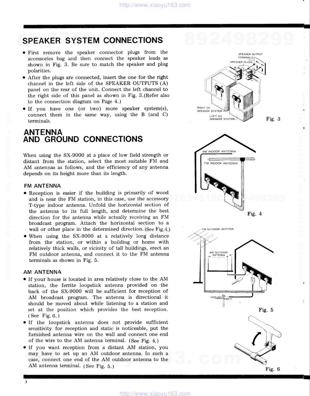
SPEAKHR SYSTEM CONNECTIONS
o First remove the speaker connector plugs from the
accessories bag and then connect the speaker leads as
shown in Fig. 3. Be sure to match the speaker and plug
polarities.
o After the plugs are connected, insert the one for the right
channel in the left side of the SPEAKER OUTPUTS (A)
panel on the rear of the unit. Connect the left channel to
the right side of this panel as shown in Fig.3.(Refer also
to the connection diagram on Page 4.)
. If you have one (or two) more speaker system(s),
connect them in the same way, using the B (and C)
terminals.
ANTENNA
AND GROUND CONNECTIONS
When using the SX-9000 at a place of low field strength or
distant from the station, select the most suitable FM and
AM antennas as follows, and the efficiency of any antenna
depends on its height more than its length.
FM ANTENNA
o Reception is easier if the building is primarily of wood
and is near the FM station, in this case, use the accessory
T-type indoor antenna. Unfold the horizontal section of
the antenna to its full length, and determine the best
direction for the antenna while actually receiving an FM
broadcast program. Attach the horizontal section to a
wall or other place in the determined direction. (See Fig.4.)
o When using the SX-9000 at a relatively long distance
from the station, or within a building or home with
relatively thick walls, or vicinity of tall buildings, erect an
FM outdoor antenna, and connect it to the FM antenna
terminals as shown in Fig. 5.
AM ANTENNA
o If your house is located in area relatively close to the AM
station, the ferrite loopstick antenna provided on the
back of the SX-9000 will be sufficient for reception of
AM broadcast program. The antenna is directional it
should be moved about while listening to a station and
set at the position which provides the best reception.
( See Fig. 6. )
. If the loopstick antenna does not provide sufficient
sensitivity for reception and static is noticeable, put the
furnished antenna wire on the wall and connect one end
of the wire to the AM antenna terminal. (SeJfig. +.;
o If you want reception from a distant AM station, you
may have to set up an AM outdoor antenna. In such a
case, connect one end of the AM outdoor antenna to the
AM antenna terminal. (See Fig. b.)
RIGHT CH
SPEAKER SYSTEM
LEFT
CH
Fig. 3
SPEAKER
SVSTEM
Fig.
-' FM OUTDOOR ANTENNA
AM OUTDOOR
ANTENNA
Fig. 5
www. xiaoyu163. com
QQ 376315150
9
9
2
8
9
4
2
9
8
TEL 13942296513
9
9
2
8
9
4
2
9
8
0
5
1
5
1
3
6
7
3
Q
Q
TEL 13942296513 QQ 376315150 892498299
TEL 13942296513 QQ 376315150 892498299
http://www.xiaoyu163.com
CONNECTION
DIAGRAM
N O T E :
lf connecting one set of speaker sys-
tems to speaker output terminal the
speaker of each channel should be 4
to
| 6 ohms : however,
both outPut
terminals (A, B and C speakers)to two
speaker systems the of each channel,
8 t o
1 6 o h m s .
AM ANTENNA
AM FERRITE ANTENNA
PRE OUT
& MIXING REC.
pAE & t,,tntN
M A I N I N
J N T f R
C O U P L E D
P H O N O
M A G
I M A G 2
SPEAKER PLUGS
SPEAKER OUTPUTS i4 to | 6() r
CENTER
CHANNE
OUTPUT
lo)t
Y7
e*cl
TAPE
REC P.B
/^
TAPE
TAPE
MON A REC. A
I
:'l-
-4,
Ir
FUSE
5 A : 2 4 0 V
220V
3 4 : | 3 0 V
| 20v
| 1 0 v #
@
TURNTABLES
(RECORD PLAYERS)
GROUNDING
The SX-g000 will provide stable performance whether
grounded or not. In rare case, however, grounding may
help. If so, connect a wire from the GND terminal to a
water pipe or balcony, fastening it FIRMLY. Never use a
gas pipe as a ground.
MICROPHONE
CONNECTION
Insert the plug on the microphone cord into either one of
the MIC jacks on the front panel of the unit.
Use both jacks when you wish to employ two microphones
at the same time.'
o e r ! !
f . . .
TAPE DECK OR TAPE RECORDER
MICROPHONE
A
(LEFT
CH.)
TURN
. If the tur
cartridge,
1 termina
crystal car
Connect t
right to tl
either terr
o A second
used, con
. If a tumt
used, eith
separate h
. Some tur
terminals
with the s
www. xiaoyu163. com
QQ 376315150
9
9
2
8
9
4
2
9
8
TEL 13942296513
9
9
2
8
9
4
2
9
8
0
5
1
5
1
3
6
7
3
Q
Q
TEL 13942296513 QQ 376315150 892498299
TEL 13942296513 QQ 376315150 892498299
http://www.xiaoyu163.com
FM INDOOR ANTENNA
H E D
-l
--1
-!
FM OUTDOOR ANTENNA
NTABLE CONNECTION
:re tuintable is equipped with a moving-magnet type
:idge, connect its output cords to the PHONO MAG
rminais on the rear of the unit. If the turntable has a
bal ca'tridge, connect it to the AUX 1 terminals.
nect the left channel cord to the upper terminal, the
b to the lower. If the cartridge is of monophonic type,
:r terminal will do.
:cond turntable with magnet type cartridge is to be
l, conoect its cords to the PHONO MAG 2 terminals.
turntable with a moving-coil (MC) cartridge is to be
l, either a matching transformer for MC cartridge or
rate head amplifier must be employed.
Le turntable output cord plugs do not match the
rinals of this unit. In such a case, replace the plugs
L the spares provided in the accessories bag.
PI()NEER
TAPE DECK (RECORDER)
CONNECTION
. A tape deck connected to this unit must have a
record/playback preamplifier built-in. PIONEER's models
T-600
and T-500
feature characteristics ideally suited
to the SX-9000.
o The connected tape recorder should also have output
terminals for tape recorder connection (LINE OUT) or
tape monitor terminals.
CONNECTION FOR TAPE RECORDING
Connect this unit's TAPE REC terminals to the signal input
(LINE IN) terminals of the tape deck. Use the cords
provided with the deck. The upper terminal is for the left
channel, the lower for the right. If the tape deck is of
monophonic type, use the CENTER CHANNEL output
terminal instead.
CONNECTION FOR TAPE PLAYBACK (OR MONITOR)
Connect the LINE OUT or TAPE MONITOR terminals on
the tape deck to the TAPE MON terminals on this unit.
Connection is done in the same way as described in the
above paragraph.
USE OF RECORD/PLAYBACK CONNECTOR
The tape deck has a DIN type record/playback connector,
all recording and playback connections can be made by
means of this one (optional) cord. Plug one end into the
TAPE REC/P.B. connector on this unit and the other into
the corresponding connector on the tape deck. In this case
no other connection cords are necessary.
CONNECTION FOR MIXED RECORDING
Connect the tape deck input terminals and this unit's PRE
OUT & MIXING REC terminals. Connection is made in the
same way as outlined above.
CONNECTION WHEN USING TWO TAPE DECKS (RE-
CORDERS)
When using two tape decks, for example, when you wish to
edit an already-recorded tape or practice along with a
recorded concert, etc., and then hear the results, connect
the second tape deck to the TAPE MON B and TAPE REC
B jacks on the front of the SX-9000. These jacks take 1/4"
standard phone plugs.
www. xiaoyu163. com
QQ 376315150
9
9
2
8
9
4
2
9
8
TEL 13942296513
9
9
2
8
9
4
2
9
8
0
5
1
5
1
3
6
7
3
Q
Q
TEL 13942296513 QQ 376315150 892498299
TEL 13942296513 QQ 376315150 892498299
http://www.xiaoyu163.com
FRONT PANEL FACILITIES
Push once to switch on the power, once again to turn
it off.
PHONES JACKS
These phones jacks for stereo headset(s).
The two jacks (A, B) are available for connection with
two stereo headsets.
T U N I N G I
When selecti
pointer of th
possible.
For an FM
way. Precisi
that the dial
T U N I N G
This knob is
the tunir'g
TONE
INDICATO
BALANCE
Used to adju
right chan
channel sou
MODE SIIVI
Controls the
unit as fol
REV: S
Right
spea
f,eft
Turn this knob to the right to
the left to reduce them. Set
position for flat response.
T R E B L E
Use of this knob is similar to that of the BASS knob.
R E V E R B
This is the reverberation adjustment knob. Turn it to the
right to increase reverberation, to the left to reduce it.
accentuate bass tones, to
the knob at its center
Use this filter to cut out low-frequency
ference, such as motor rumbling or hum.
Use this filter to cut out high-frequency
ference, such as that from fluorescent
F M M U T I N G
This switch is used to suppress much noise between FM
stations when tuning. In a fringe area, however, this
switch should be kept off because it may suppress the
desired station signal at the same time.
LOUDNESS
At reduced volume the ear's sensitivity to extremely low
and high frequencies is reduced. This switch compensates
for that phenomenon by emphasizing these frequencies.
At normal or high volumes this switch should be kept
off.
TAPE MON B JACK
This jack is for connecting to the LINE OUT terminals
of a tape deck or tape recorder. It is designed to accept a
3-P type plug.
TAPE REC B JACK
For connecting to the LINE IN terminals of a tape deck
(recorder). Allows recording of another program source
or tape for editing.
F I LTER
LOW:
HIGH:
ST:
LT:
T O N E
C O L O R
aa
s
92
A M
5 5
6 c t
7 0
F M S T E R E o
A M
O F F
O N
P O \ A / E R
6
P H
e
tc
www. xiaoyu163. com
QQ 376315150
9
9
2
8
9
4
2
9
8
TEL 13942296513
9
9
2
8
9
4
2
9
8
0
5
1
5
1
3
6
7
3
Q
Q
TEL 13942296513 QQ 376315150 892498299
TEL 13942296513 QQ 376315150 892498299
http://www.xiaoyu163.com
N G I N D I C A T O R
selecting an ANI broadcast, tune so that the dial
er of the lower meter deflects as far to the right as
ble.
an FM broadcast, use the lower meter in the same
Precision FM tuning is also possible by adjusting so
the dial pointer of the upper meter is ceutered'
This knob is used to adjust the volume of AM and FM
broadcasts, record play and tape playback' It is also
used to balance the program source signal level during
mixed recording with a microphone'
RCE VOLUME
ASTER VOLUME
Turn this knob to the right
the speakers. If this knob is
sound will come frorn the
SOURCE and MIC LEVEL
all the waY to the right.
S P E A K E R S
A
B
c
T O N E
C O L
I N G
knob
unir'g
E COLOR
CATOR
REVERBERATION
INDICATOR
is used to locate AM or FM stations' Watch
meter(s) for more Precise tuning-
to increase the volume from
turned down all the waY no
speakers, even though the
volume controls are turned
S E L E C T O R
P H O N O 1
T U N I N G
I E
C O L O R
s
s 2
s 1
s 6
9 A
1 O O 1 O 2 1 O 4
1 0 6 1 O 8
M H z
:l-
; - ; - ;
t "
t " "
1 2 o
1 4 o
1 6 0
x l o k H z
o
o
o
F M
P H O N O
A U X
\ S S
T R E E } L E
V O L U M E
B A S S .
l .
v t v l o
M I N
M A STER
Q-
souace
A N C E
MIC LEVEL CONTROLS
() r:torueen
R E V E R B
E R A T I O N
o
d to e.djust the stereophonic balance between left and
Lt channels. Turning to the left strengthens the left
nnel sound; to the right, the right channel'
LANCE CONTROL
DE SIIIITCH
rtrols the stereo aud mono output functions of the
t as foliows .
V:
Stereo, with
right
arld
r3versed.
r
Normal stereo.
:
Left channel sigual fed
speakers.
:
Ii.,ight channel
speakers.
signal fed
P U S H
O N
M U T I N G
L o
left chairnel siglals
to both left and right
to both left and right
channel sigr-rals mixed, then fed
right channel sPeakers.
Control the microphone signal input level'
Control A is for a microphone connected to MIC JACK
A, and Control B for MIC JACK B' Turning either to the
right increases the signal.
Ul"roplrones can be used at any time, for mixing with
another sound source' such as a record or recorded tape'
When a microphone is not being used, that control
should be turned all the way to the left (off)'
NOTE:
When only one microphone is used' its signal is monaurally fed
through both left and right speakers' regardless
of which iack is
useo.
When two microphones are used' however' the one connected
to jack A broadcasts through the left speakers' while the one
connected to iack B is heard through the right'
M O N .
B.l
J
M I C
L E r F:,:
.
L " (
T O N E
R:
l,eft ar-rd right
tr both left and
www. xiaoyu163. com
QQ 376315150
9
9
2
8
9
4
2
9
8
TEL 13942296513
9
9
2
8
9
4
2
9
8
0
5
1
5
1
3
6
7
3
Q
Q
TEL 13942296513 QQ 376315150 892498299
TEL 13942296513 QQ 376315150 892498299
http://www.xiaoyu163.com
'
PIONEER
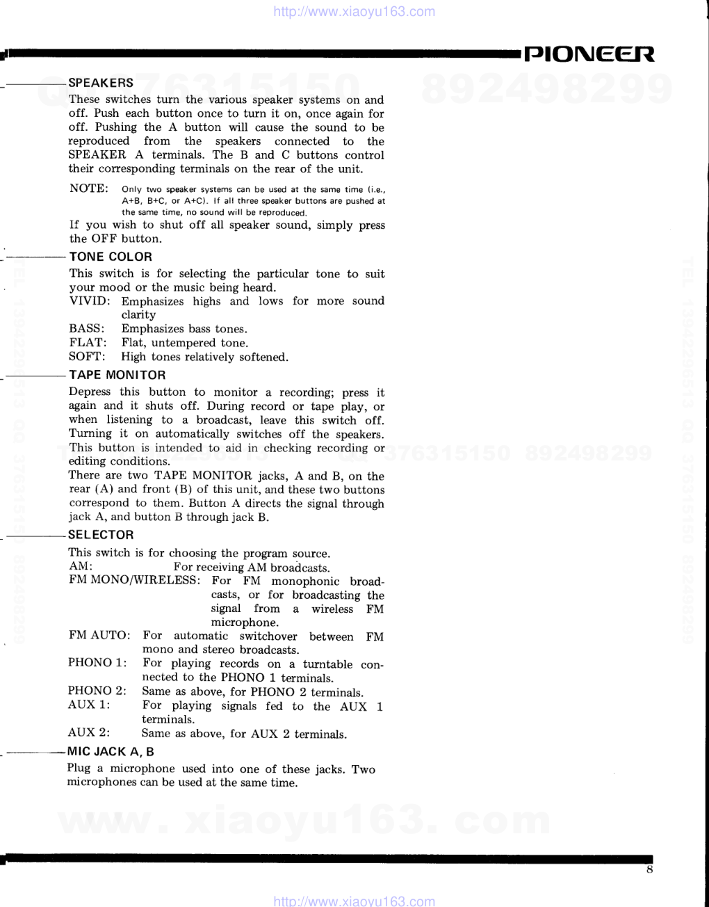
SPEAKERS
These switches turn the various speaker systems on and
off. Push each button once to turn it on, once again for
off. Pushing the A button will cause the sound to be
reproduced from
the
speakers connected to
the
SPEAKER A terminals. The B and C buttons control
their corresponding terminals on the rear of the unit.
NOTE:
Only two speaker systems can be used at the same time (i.e..
A+8, B+C, or A+C). lf all three speaker buttons are pushed at
the same time, no sound will be reproduced.
If you wish to shut off all speaker sound, simply press
the OFF button.
TONE COLOR
This switch is for selecting the particular tone
.
your mood or the music being heard.
VIVID:
Emphasizes highs and lows for more
clarity
BASS:
Emphasizes bass tones.
FLAT:
Flat, untempered tone.
SOFT:
High tones relatively softened.
TAPE MONITOR
Depress this button to monitor a recording; press it
again and it shuts off. During record or tape play, or
when listening to a broadcast, leave this switch off.
Turning it on automatically switches off the speakers.
This button is intended to aid in checking recording or
editing conditions.
There are two TAPE MONITOR jacks, A and B, on the
rear (A) and front (B) of this unit, and these two buttons
correspond to them. Button A directs the signal through
jack A, and button B through jack B.
SELECTOR
This switch is for choosing the program source.
AM:
For receiving AM broadcasts.
FM MONO/WIRELESS: For FM monophonic broad-
casts, or for broadcasting the
signal from
a wireless FM
microphone.
FM AUTO:
For automatic switchover between FM
mono and stereo broadcasts.
PHONO 1:
For playing records on a turntable con-
nected to the PHONO 1 terminals.
PHONO 2:
Same as above, for PHONO 2 terminals.
AUX 1:
For playing signals fed to the AUX 1
terminals.
Same as above. for AUX 2 terminals.
MIC JACK A, B
Plug a microphone used into one of these jacks. Two
microphones can be used at the same time.
to suit
sound
AUX 2:
www. xiaoyu163. com
QQ 376315150
9
9
2
8
9
4
2
9
8
TEL 13942296513
9
9
2
8
9
4
2
9
8
0
5
1
5
1
3
6
7
3
Q
Q
TEL 13942296513 QQ 376315150 892498299
TEL 13942296513 QQ 376315150 892498299
http://www.xiaoyu163.com
RECEPTION
OF FM
1. Set the SELECTOR switch to FM STEREO.
2. Turn the MUTING switch on (unless the signal strength is
very low-then leave it off).
3. Tune in the desired station while watching the TUNING
meters.
Best reception is obtained when the dial pointer of the
Iower meter deflects as far to the right as possible for that
station, while that of the upper meter is centered.
If the broadcast is stereo. the FM Stereo indicator will
light up. It remains unlit if the broadcast is monophonic,
and the set automatically switchover for monophonic
a. ffi::1""Ting is complete,
slowly turn up the VoLUME
SOURCE and MASTER knobs until the proper level is
achieved.
Then adjust the BASS, TREBLE, TONE COLOR and
other controls for the most pleasing sound.
5. To increase reverberation, turn the REVERB knob to the
right.
For FM reception located far away from the station, or
when external noise is high, reception can be improved by
setting the SELECTOR to FM MONO. In this case,
however, stereo programs will be received as monophonic.
RECEPTION
OF AM
1. Set the SELECTOR switch to AM.
2. Tune in the desired station while watching the lower
TUNING meter. Tune so that the dial pointer deflects as
far to the right as possible for that station-
3. After tuning is complete, slowly turn up the VOLUME to
the desired level, then adjust the BASS, TREBLE and
TONE COLOR controls.
4. To increase reverberation, turn the REVERB knob to the
right.
If noise is extremely high during both FM and AM
'reception,
the problem could be in the antenna and
. ground. Reread the section, ANTENNA CONNECTION
AND GROUNDING, page 3.
LISTENING
TO RECORDS
1. Set the SELECTOR switch to PHONO 1 or PHONO 2.
To use the turntable connected to the PHONO 1
terminals, set to PHONO 1, for that connected to PHONO
2,setto PHONO 2.
2. If tbe record is monophonic, set the MODE switch to
either L or R.
3. Adjust the VOLUME, BASS, TREBLE and TONE
COLOR controls.
4. To increase reverberation. turn the REVERB knob to the
right.
www. xiaoyu163. com
QQ 376315150
9
9
2
8
9
4
2
9
8
TEL 13942296513
9
9
2
8
9
4
2
9
8
0
5
1
5
1
3
6
7
3
Q
Q
TEL 13942296513 QQ 376315150 892498299
TEL 13942296513 QQ 376315150 892498299
http://www.xiaoyu163.com
TJIONEEfiI
USING MICROPHONES
The SX-9000 permits the use of two microphones at once,
for such purposes as recording a concert in stereo; even
performances or dramas in large theaters can be efficiently
recorded.
1. Turn the VOLUME - SOURCE knob all the way down if
microphone recording only is desired. If mixed recording,
combined with music from a record, etc., is desired, set
the SOURCE knob to the best level.
2. Tii,e MIC LEVEL A knob controls the input from a
microphone plugged into MIC jack A; knob B controls
jack B. Tum either of these knobs to the right to increase
input signal strength. Adjust the level while watching for
"howling"
(acoustical feedback of the speaker signal
through the microphone). If this occurs, reduce the
volume or separate the microphone(s) and speakers. If
only one microphone is used, plug it into either jack. If
setting the MIC LEVEL for another jach not being used to
OFF, the sound will be reproduced from both speakers.
NOTE:
When adjusting the MIC LEVEL control, be careful not to cause
howling.
Howling is of course unpleasant to hear, but it can also damage
the VU meter of your tape recorder or deck during recording.
3. If two microphones are used, the one connected to jack
A will broadcast over the left channel, B the right. If you
wish to use only one of these microphones at any time,
tum the unused microphone level control off. Then the
microphone used will broadcast over both channels.
USING TAPE DECKS
AND TAPE RECORDERS
As shown in Fig. 9, signals heard from the speakers are
normally fed to the SX-9000 TAPE REC A and B terminals.
When recording, set the SELECTOR and MODE switches to
your program source. Refer to the sections on Listening to
Broadcasts and Listening to Records. Recording signals
cannot be regulated by the SX-9000 VOLUME, BASS,
TREBLE and TONE COLOR switches. These must be
adjusted by the recording level control on the tape deck/tape
recorder.
NOTE:
When using mono tape recorders, either the left channel signal or
the right channel signal may be recorded, but not both. The
CENTER CHANNEL terminal should therefore be used.
TAPE MONITOR
With 2-head and 3-head type tape recorders fitted with
monitor mechanisms, turning the TAPE MONITOR switch
ON during recording has the following effects (if recording
and playback heads are first connected): With the 2-head
type, signals fed to the recording head can be monitored;
with the 3-head type, signals can be monitored immediately
after recording. ( See Fig. 9. )
TAPE DECK B
. . . o I a - - -
...aro.--
sx-9000
1 0
www. xiaoyu163. com
QQ 376315150
9
9
2
8
9
4
2
9
8
TEL 13942296513
9
9
2
8
9
4
2
9
8
0
5
1
5
1
3
6
7
3
Q
Q
TEL 13942296513 QQ 376315150 892498299
TEL 13942296513 QQ 376315150 892498299
http://www.xiaoyu163.com
PLAYBACK
. Turn TAPE MONITOR SWITCH A or B ON and adjust the
VOLUME, BASS, TREBLE and TONE COLOR switches to
the desired levels.
o When TAPE MONITOR SWITCHES A or B are turned ON,
the position of the SELECTOR becorries immaterial.
M I X E D R E C O R D I N G
When using a microphone in mixed recording, connect the
tape deck to the PRE OUT terminal and adjust the volume of
the microphone with the MIC LEVEL knob while listening to
the record or broadcast. Do not turn this knob too high as
this will result in howling and may damage the VU meter of
the tape deck.
EDITING RECORDING TAPES
By using two tape decks and re-recording only certain parts
of a tape, you can edit old tapes taken from FM broadcasts,
etc. and obtain a brand-new tape containing only your
favorite recordings:
1. As shown in Fig. 10, place the old tape or mother tape on
TAPE DECK A and turn TAPE MONITOR SWITCH
A ON.
2. Place the new tape on TAPE DECK B.
3. Playback is performed on TAPE DECK A and recording
on TAPE DECK B.
By tuming TAPE MONITOR SWITCH B ON and OFF
you can monitor the recording. Be sure not to turn TAPE
MONITOR SWITCH A OFF.
YOU CAN ALSO
USE YOUR SX-gOOO AS FOLLOWS
MULTICHANNEL AMPLIFIER SYSTEM
By using an ELECTRONIC CROSSOVER NETWORK
(PIONEER MODEL SF-700) and one or two POWER
AMPLIFIERS, you can build a high-quality multichannel
amplifier system.
a. Set the PRE & MAIN switch on the rear panel of the
SX-9000 at the SEPARATED position.
b. Connect the PRE OUTPUT terminal of the SX-9000 and
the CROSSOVER NETWORK INPUT terminal. Also
connect the CROSSOVER NETWORK LOW-RANGE
OUTPUT terminal and the MAIN INPUT terminal of the
sx-g000.
c. For MID-RANGE and HIGH-RANGE a separate POWER
AMPLIFIER must be used.
3.D STEREO SYSTEM
By connecting a POWER AMPLIFIER with a low-pass filter
of
150 -
250H2 cut-off frequency to the CENTER
CHANNEL OUTPUT terminal in the rear panel, you can set
up a 3-D stereo system.
sx-9000
Fig. 10
sx-9000
...oro---
o o o o o o
o o o o
www. xiaoyu163. com
QQ 376315150
9
9
2
8
9
4
2
9
8
TEL 13942296513
9
9
2
8
9
4
2
9
8
0
5
1
5
1
3
6
7
3
Q
Q
TEL 13942296513 QQ 376315150 892498299
TEL 13942296513 QQ 376315150 892498299
http://www.xiaoyu163.com
TJIONEEFI
CONDITIONS
FREQUENTLY
MISTAKEN FOR MALFUNCTION
Noise: There are a variety of noises relating to the operation of a
from external sources of nolse. Due to the inherent high
hi-f i unit. These are generalty
divided into two types; (1) the unit
amplif ier and reproduces
extraneous noises into def inite output
is faulty (a transistor or part has deteriorated) and (2) an
noise. lf your receivel produces a noise, check according tothe
external sourceof noise isadding noiseto the unit.
following table and trace out the source of noise for the
When a hi-fi unit produces an unpleasant noase, it is often
appropriate corrective action.
assumed that the unit is faulty, but statistical records indicate
that the maiority of noises produced in hi-f i acoustic unats result
Watch for the following conditions; these are also apt to be mistaken for malfunction.
SVmptom
Suspected Source of Noise
Diagnosis
and Remedy
ao
Eo
m
o
g
o
' ?
.J
q
o
!=
Continuous or intermitten
noise like jjjjli or zzzzzz.
. Static (lightning)
o Fluorescent lamp, motor, or thermostat
may be in use in house or in the vicinity
of the house.
In manv cases, it is very diff icult to remove the source
o f n o i s e . I n o r d e r t o m a k e t h e r a d i o i n p u t l a r g e r t h a n
the noise level, set up a good outdoor
antenna and
m a k e a c o m p l e t e g r o u n d i n g
When a station is tuned in,
hum is mixed in
the
program.
r Poor fluorescent lamp, motor, or electric
heater may be in use in house or near the
house.
Reversing
the line plug may occasionally
alleviate this
noise problem. Usually it is very difficult to eliminate
tne norse.
Hissing sound noise in AM
(medium wave) reception.
I The frequency of an adjacent station is
interfering with that of the station being
tuned in (10kHz beat interference).
o TV set is on in the same house with the
rece iver.
lmpossible to remove such interference. lf the cause of
such noise is in the TV set. increase the distance
between the TV set and receiver.
Static noise (in particular,
when automobiles
run close
to the house).
a White noise generated from automobile
engi nes.
r Radio frequency sewing machine or weld-
ing machine being used near your house.
In an area surrounded by hills or high buildings, the
FM input signals are very weak. Thus the noise limiter
in the circuit loses its function. Set up an outdoor FM
antenna having many reflector elements.
Reception of
FM stereo
program contains more
noise than FM mono pro-
gram.
a Note that the service area covered by an
FM stereo broadcast is about 50% of that
of a regular mono broadcast.
Increasing
FM input signal may alleviate this problem.
Use an exclusive FM outdoor antenna instead of the
indoor T- tvpe antenna.
E
o
E.
o.=
o
o
=
Hum or buzz.
When
switched to radio reception,
the noise disappears.
a Poor connection of shielded
wire {a).
. Jack connection is loose. (b)
o Line cord or f luorescent lamo is near the
shielded wire. (c)
o Poor grounding. (d)
a Ham transmitting station or TV transmit-
ting station is near your house. (e)
Correcr the conditions stated in (a), (b). (c) or (d). ln
case of (e), report it to an ofJicial activity.
Output tone quality is
poor and mixed with noise.
Treble is not clear.
. Stylus is worn out. (a)
. Record is worn out. (b)
a Dust adheres to stvlus. (c)
. Stylus is improperly mounted. (d)
a Stylus pressure is not proper. (e)
r The TREBLE level is too hiqh.
Check (a) through (e) and correct the condation.
Lower the TREBLE level.
Symptom
Suspected Source of Noise
D i a g n o s i s a n d R e m e d y
Power is not turned on
although the power switch
rs set to ON.
o Fuse blows. (a)
. Line plug is loose. (b)
C h e c k ( a ) a n d ( b ) a n d c o r r e c t t h e c o n d i t i o n .
In playing a record, in-
creasing the volume causes
howling.
a Distance between the turntable and the
soeakers is too short.
a The place on which the turntable or
soeakers are set is unstable.
Change the distance or rearrange the installataon
increase of the unit and speakers. (lnstalling the
turntable on a firm, solid stand may alleviate this
oroblem.)
Do not enhance the BASS sound level excessavely.
TZ
www. xiaoyu163. com
QQ 376315150
9
9
2
8
9
4
2
9
8
TEL 13942296513
9
9
2
8
9
4
2
9
8
0
5
1
5
1
3
6
7
3
Q
Q
TEL 13942296513 QQ 376315150 892498299
TEL 13942296513 QQ 376315150 892498299
http://www.xiaoyu163.com
SPECIFICATIONS
SEMICONDUCTORS
Audio Section
Transistors
Diodes
Tuner Section
IC's
FET
Transistors
Diodes
AUDIO SECTION
Music Power Output
Continuous Power
Output (Each channel
driven)
Continuous Power
Output (Both channel
driven)
Harmonic Distortion
Damping Factor
Frequency Response
Power Bandwidth
Hum and Noise
Sensitivity and Impedance
(at 1kHz, continuous
power output)
Output Jacks and
Terminals
Equalization Curve
BASS Control
TREBLE Control
Filters
8A
150 watts total (IHF
rating)
4A 240 watts total
Be 62wl62w (1kHz)
4a 85w/85w (1kHz)
8O 50w + 50w (lkHz)
4A 60w + 60w (lkHz)
Less than 0.57o (at 1kHz,
continuous power output)
30 (at 8f2, lkHz)
l-OHz to 35kHz. tldB
10Hz to 35kHz (IHF rating)
PHONO MAG
more than B0dB
AUX
.............more
than 100dB
PHONO MAG (1,2)
...............2.5mV,
50kQ
AUX (1,2)
..............160mV.
50kA
TAPE MONITOR (A,B)
..............160mV.
5OkO
MICROPHONE (A,B)
...............1.6mV,
65kO
MAIN INPUT
............500mV,
180kQ
Speakers
(A,B,C) 4 to 16 ohms
Stereo Headphones
Jacks (A,B)
TAPE RECording Jacks (A,B)
TAPE REC/P.B. Connector
(DIN type)
PRE OUTPUT
500mV. 13kSl
PHONO.....RIAA
+12.5dB, -14dB (at 50Hz)
+9dB. -11dB (at 10kHz)
LOW.......Cut 6dB (at 50Hz)
HIGH.....Cut 12dB (at LOkHz)
47
1 1
5
t-
12
11
www. xiaoyu163. com
QQ 376315150
9
9
2
8
9
4
2
9
8
TEL 13942296513
9
9
2
8
9
4
2
9
8
0
5
1
5
1
3
6
7
3
Q
Q
TEL 13942296513 QQ 376315150 892498299
TEL 13942296513 QQ 376315150 892498299
http://www.xiaoyu163.com
PIONEER
Loudness Contour
Reverberation
TONE COLOR Switch
MlCrophone Mixing
FM TUNER SECTION
Frequency Range
IHF Sensitivity
Capture Ratio
Selectivity
Image Rejection
Signal to Noise Ratio
Antenna Input
FM MPX SECTION
Circuit
Channel Separation
Harmonic Distortion
AM TUNER SECTION
Frequency Range
IHF Sensitivity
Image Rejection
Antenna Input
MISCELLANEOUS
Power Requirements
Power Consumption
Dimensions (Overall)
Weight
Switchable to ON-OFF
+12dB (at SOHz), +7dB (at
10kHz). with VOLUME control
set at-4OdB, VOLUME
Reverberation easily control-
lable
4-position knob for "VIVID",
"BASS", "FLAT" and "SOFT"
Stereo
.....through both "A" and
"B" channels
Monophonic
.....through either "A" or
"B" channel
87.5MHz to 108MHz
1.6pV (at 98MHz)
1dB (at 98MHz)
40dB (at 98MHz)
90dB (at 9BMHz)
More than 65dB
300ohms balanced
Time-switching type demodu-
lator
FM
Mono-Stereo automatic
selection
40dB (at lkHz)
O.B7o
(at lkHz) 100% Mod.
525kHz to 1,605kH2
9.5rrV
78dB (at 1,000kH2)
Built-in ferrite loopstick
antenna
110, 120, 730, 220 and 240
volts (switchable)
350 VA (310W) MAX.
20-9176" 522 mm (width)
7-518"
194 mm (height)
13-9/16" 344 mm (depth)
Without Package 34 lb 8 oz
16.7 kg
With package 42lb 3oz L9.2kg
www. xiaoyu163. com
QQ 376315150
9
9
2
8
9
4
2
9
8
TEL 13942296513
9
9
2
8
9
4
2
9
8
0
5
1
5
1
3
6
7
3
Q
Q
TEL 13942296513 QQ 376315150 892498299
TEL 13942296513 QQ 376315150 892498299
http://www.xiaoyu163.com
ALIGNMENTINSTRUCTIONS
SECTION
terminal of f ront-end f rom lN
S E L E C T O R . . , . . F M M O N O
M U T I N G . . . . . . . O F F
V o l u m e C o n t r o l S e t t i n g :
F u l l y C o u n t e r c l o c k w r s e
ALIGNMENT OF FM
D i s c o n n e c t
O U T P U T
P o s i t i o n o f S w i t c h :
t e r m i n a l o f l F u n i t
A lignment
I n p u t
L e v e l
D i a l
S e t t i n g
O ut Put
EquiPment
C onnect ions
STEPS
A dj ust
R e m a r k s
E qu ipment
C onnect tons
F requencY
iil""
U n i t
Adjust
for
maxlmum
sensitivitY and sYmme'
t r i c a l c h a r a c t e r i s t i c s
S w e e p G e n e r a t o r
lN terminal
of lF unit
1 0 . 7 M H z
4 0 d B
O scilloscope
,4-h
\9
termrnal
Check sYmmetrY of curve
2
8 0 d B
M I F
niI 4.7 FF
in detector clrcu
O scilloscoPe
OUT terminat
3
R e m o v e e l e c t r o l y t l c
c a f 'acitor C rz (ol
T + o f
l F U n i t
Adjust the Primary core
of T a so that slope of
straight Portion of : S"
curve will become the
steepest and adjust the
secondarY core so that
the center of : S" curve
w i l l c o i n c i d e w i t h t h e
center of the marker'
A
S we e P G enerator I
I
lN t e rminal
|
10 TMHZ
I
of lF unit
II
c o n n e c t O U T P U T t e r m i n a l o f f r o n t - e
4 0 d B
nd to lN terminal of lF unit
__------..-
l A d i u s t
f o r
m a x r m u m
l s e n s i t i v i t Y a n d s Y m m e
I trical characteristics
5
Sweep Generator
1 0 . 7 M H z
P o i n t o f
n o I n t e r -
ference as
near as
8 8 M H z
O scilloscope
@
term inal
T z o I
front-end
6
4 0 d B
Check symmet r y o f c u r v e
I O F
--
T P of F ront
O scil loscope
O U T t e r m i n a l
T q o f
l F U n i t
s i m i l a r l Y
8
e n d
c a p a c i t o r C t , \ 4 . 7 l t F )
-- ^;--1
;"tsq-
-] Adjust
for
maxlmum
d e f l e c t i o n
9
1 0
Connect electrolYt r c
G
t
l-;;l
,.."
9 0 M H z
O scil loscoPe
' . ] ( + o o H
f::
C T + o f
front-end
1 l
t e r m r n a l
lr11i I o u r t
I
L r . r l ,
I
| : O T
f ront -end
Adjust
to(
maxlmum
d e f l e c t i o n
I 2
F M A n t e n n a
t e r m i n a l
R e p e a t S T E P S
j
1 o 6 M H z
L 3 a n d 1 4 s e v e r a l
l 0 d B
( 4 0 0 H
30,,/o )
I O 6 M H z
I
OscilloscoPe
] V T V M
O U T t e r m t n a t
i 3
Q f ' , C T z ,
C T : o f
f r o n t - e n d
l 4
l i m e s
1 5
www. xiaoyu163. com
QQ 376315150
9
9
2
8
9
4
2
9
8
TEL 13942296513
9
9
2
8
9
4
2
9
8
0
5
1
5
1
3
6
7
3
Q
Q
TEL 13942296513 QQ 376315150 892498299
TEL 13942296513 QQ 376315150 892498299
http://www.xiaoyu163.com
PIONEEFI
A L I G NME NT OF MPX
P o s i t i o n o f S w i t c h :
V o lu me Co n t rol Settino
I n p u t S i g n a l :
SECTION
S E L E C T O R . . . F M A U T O
M U T I N G . . . O F F
F u l l y C o u n t e r c l o c k w i s e
Main ( L+ R) 4 0 . 5 K H z D e v i a t i o n ( . 6 0 , ) o
)
l 9 K H z P i l o t 7 . 5 K H z D e v i a t i o n ( I O % )
S T E P S
C i r c u i t t o b e
C onnect
A I i g n m e n t
a d j u s t e d
C o n n e c t i o n s
S ignal
R e m a r k s
+ - - - ' -
l
1
2
M P X S G t o t r M
S e p a r a t i o n A n t e n n a
t e r m i n a l
S u b
AC VTVI\4
( L - R )
X L L
t e r m i n a l
L o r R
L o r R
f o r m a x i m u m d e f l e c t i o n
A d j u s t f o r m i n i m u m d e f l e c t i o n o f
o t h e r c h a n n e l .
V R r
ALIGNMENT OF AM
SECTION
* V TV M a n d o sc illoscopeshould be connecte d i n p a r a l l e l a t t h e o u t p u t .
P o s i t i o n o f S w i t c h : S E L E C T O R . . . . . . . . . . . . . . . . . . M W
V o lu me Co n t rol Setting: Fully Counterclock w r s e
I
A dlu st
I
n emart",1
T
E1
I^J
L M
x
4
Or
t
-o2q I
or LM7O3L
@
o-----r-t--
^
-
?
3
1
,
r
l
#4"'l)\*-='
-:? | ;,fa
tflYl=L L,'
- l - l
I
I l T
? -
', | ,, l"v, l'
L-4M.J
I
n' ,
^
Rn33(
l__^
?-
"*=
t
l
-
vr,
,7"
w t 2 .
(
B
i
+t2v
40ma
t N ((
(
E
l
www. xiaoyu163. com
QQ 376315150
9
9
2
8
9
4
2
9
8
TEL 13942296513
9
9
2
8
9
4
2
9
8
0
5
1
5
1
3
6
7
3
Q
Q
TEL 13942296513 QQ 376315150 892498299
TEL 13942296513 QQ 376315150 892498299
http://www.xiaoyu163.com
MPX UNIT
w l 3 - o . 2 6
. B @
Lour@
E
@
Rour@
t 2 v ! 0 . 6 v
9 . 5 n A
@ N4ur
@ t w
e E
@auro
@ v ,
t 5 l
q L P F r l | -
L:fl
s
T - - - -
I
^ l
D r
-r"rs+---il-
i
, c,1!')-6t
t5t88 | _
rqil*
t &
I
I
I,_
Rze33K Ra 33K
--------o
IND
Ino= 30 mA mu.
www. xiaoyu163. com
QQ 376315150
9
9
2
8
9
4
2
9
8
TEL 13942296513
9
9
2
8
9
4
2
9
8
0
5
1
5
1
3
6
7
3
Q
Q
TEL 13942296513 QQ 376315150 892498299
TEL 13942296513 QQ 376315150 892498299
http://www.xiaoyu163.com
AM TUNER UNIT
w r 4 - o l 5
25C3A2
Rd
Tr T4l'00E
25C460
Rs lK
T3 T7l'025
25C460
-|n_Illjj2s_
0.1
t l
l l
l l
t l
t i
0,2
i l
iir l
I I
q3
l l
l r
t l
t l
- - 1 - - -
"" RG t0(
-T-
--T-
t ,
l '
n
a
l
V7/.
GNO +B IFO{JT
@ our
4l0Ptr
Ij
vco
?+ 1;
- l l -
m m
-r--\^
= e
: .I= ilt:
s
e af\
iT
?&
- ,h' -,h.k
www. xiaoyu163. com
QQ 376315150
9
9
2
8
9
4
2
9
8
TEL 13942296513
9
9
2
8
9
4
2
9
8
0
5
1
5
1
3
6
7
3
Q
Q
TEL 13942296513 QQ 376315150 892498299
TEL 13942296513 QQ 376315150 892498299
http://www.xiaoyu163.com
53 I/2 R
= E
z Z =
a
;
F
=
s
E E
g E H
Sr l+F
r"r @ r+
Av
o^
d'f]ft
9oX6P
Ee is-A
d ;
\ / \ ,
< a
tsF
=>
€
I
It
.
/
f
I F M I
t
l
< l
z l
z l
g I G N D
z l
I A M
+ E
l >
r"v
(e)
@ o@-
^"V/ r^)
o o@:
TAPE il,'l B
fT6-ofiVl
TAFE REC B
Fxi-;n
PHONo 2
lZtmTl
PHONO I
t10/117
/ 130/22u210
5 0 - 6 0 H 2
-(
u1l
,l
ill
zl.I
.(
PI
, I
6 i
2 \
2 l
I I"t
CENTER CHANNEL OUT
t2$JEmfl
A PHoNES
-
li4SnFl,zao
U (ATSPOUTFJT
M/8O
PHONO I
PHONO 2
M I C
A
fi.J-fl
M I C B
fI6 mV]
G N O
S r
')r'
SPEAKERS OUTPUTS
tr|Ft/sn
E
D
C
E
SELECTOR SWlrcH ( sl3 -o38 )
2. FM MONO
3, FM AUTO
4
PHONO I
5. PHONO 2
6
A U X
I
7 . A U X
2
MODE SWITCH
{Sr4-O35)
I . R E V
2 . S T
3. LT
4. RT
5 . L + R
Sa
S 5
TONE CoLOR S{lrCH (Sls-O35 )
L V r V 0
2. BASS
3.
FLAT
4-
SOFT
MIC A SWITCH ( VR, )
MIC B SWITCH {vR! )
O F F - O N
REVERB SWITCH tVR6 )
OFF eON
INTEROUPLED
SWITCH ( S4I-O22 )
INTERGUPLED
<+
PRE a MAIN SEPARATED
56
POWER
swlTCH
(Sll-o3o)
ss
LINE VoLTAGE
SELECTOR
( sll-ola )
oFF Atc^t/t20JA30v / t20V/240V
vRrd!
SOURCE
VoLUME (C88-OlO)
VRao MASTER
VOLUME (C88-0lO)
VRz
MIC A VOLUME ( C8s-056)
vR.
Mtc B voLUME ( C85-O56)
VR5
BALANCE
VOLUME
( C85-O52)
VR6
REVERB VOLUME { C85-O55)
<-
''..-- D.C CURRENT
A
-AT NOSIGNAL INPUT
G)
-----Ar 60warrs ourPUT
D,C VOLTACE
V -,
AI NO SIGNAL INPUT
O
----AT 60wATr ouTpuT
fl'
---- rNpur oR ouRr
VoLTAGE aoQUIRED
75 WATTS oUTPUT AT I K Hz ( R [,1.S )
FM IF UNIT
wl2-o28
o @
\9 /'^
o ( (
@rx
AM TUNER UNIT
w 1 4 - o t 5
3
1
4
5
8
9
R. 2.2K
Rr 2 2K
+83
1 C
N
to
o - c
I
( ) r c
= ^
hz
d X
) i t
o C o
O N
u =
ztr
6
4
Fz
r 6
( ) o
L
r
i o
; =
UJ
9 1 0
Ezt G l
<
l
^
N
a =
u
I
o-t( )) o l
^ r Y z 6 6 '
/
Q, @(9
PUSH SWITCH UNIT
w 26- OO3
INl
IN2 OJT] OUT2
o '
t '
42 REVERB AMP
E2
UNIT OUT
lj *r, - oo, '*
tN4
B I
I
l
s
UNIT 1
w26-0o"
4
3
1
2
1
5
6
6 rel
Rd
--o
4
0mn4e
-oi
Brown
Y.llw
SECT]ON ITEM NO
VACANT
R
Rr - Rzg
R30
2
c
C r - C t :
Cu
3
L
L
- L 3
Lr
Szwww . x ia o y u 1 6 3 . c o m
QQ 3 7 6 3 1 5 1 5 0
9
9
2
8
9
4
2
9
8
T E L
1 3 9 4 2 2 9 6 5 1 3
9
9
2
8
9
4
2
9
8
0
5
1
5
1
3
6
7
3
Q
Q
TEL 13942296513 QQ 376315150 892498299
TEL 13942296513 QQ 376315150 892498299
http://www.xiaoyu163.com
HEAD AMP UNIT
w 2 r - o o 2
2SC87l or 2SC458LG
22135 n:
^^ Qz
Y + /
MIC AMP UNIT
w 2 t - o o 3
Cr6 100/35
C4
30P
Rz lK
cJ.*
www.xiaoyu163.com
QQ376315150
9
9
2
8
9
4
2
9
8
TEL13942296513
9
9
2
8
9
4
2
9
8
0
5
1
5
1
3
6
7
3
Q
Q
TEL 13942296513 QQ 376315150 892498299
TEL 13942296513 QQ 376315150 892498299
http://www.xiaoyu163.com
DEMI SII.|ITCH UNIT
w 2 6 - O O l
L - _ _ _ _ _ _ _ _ _
_ - _ _ _ _ _ t
Sr :
TAPE M0NITOR A
S2 : TAPE MON1TOR B
oFF .-
ON
OFF -
ON
OEMI SWITCH UNIT
w 2 6 - O O z
-----t;---------t
@
@
@
o
I
I
I
I
I
I
i
S l
5 3 :
s4
I
LOW CUT FTLTER
OFF <+
ON
HIGH CUT FILTER
OFF -ON
MUTING
OFF -*
ON
LOUDNESS
OFF _
ON
t'-
I
t0/25
;
S
.i
6.8|( 0.0033
Rzo 2.7K
rrc
2SO456L6
2SC458LG
w 2 8 - O O l
REVERB t.rt|IT
w38 - OOI
www . x ia o y u 1 6 3 . c o m
QQ 3 7 6 3 1 5 1 5 0
9
9
2
8
9
4
2
9
8
T E L
1 3 9 4 2 2 9 6 5 1 3
9
9
2
8
9
4
2
9
8
0
5
1
5
1
3
6
7
3
Q
Q
TEL 13942296513 QQ 376315150 892498299
TEL 13942296513 QQ 376315150 892498299
http://www.xiaoyu163.com
REVERB AMP TJNIT
w 2 8 - O O 2
t
o t N 3
0 r
Q2
O3
Qa
as
06
Qr
Qa
Oe
2SCA70q 2SC45A|
zSC870 0r zSC458L
2sca7o ot 2si458t
2SC7 3 4
2SC734P o. 2SC9O4
2SA56r P or 254569
23CA7O ot 2SC45AL
23CS7O ot 2SC45AL
2sC87o or 25C458L
E 2
E 2
Qs
25C734P
Cr 33/s
www. xiaoyu163. com
QQ376315150
9
9
2
8
9
4
2
9
8
TEL 13942296513
9
9
2
8
9
4
2
9
8
0
5
1
5
1
3
6
7
3
Q
Q
EL 13942296513 QQ 376315150 89249829
EL 13942296513 QQ 376315150 89249829
http://www.xiaoyu163.com
MAIN AMP UNIT
w l 5 - o 5 2
GND
N r
22/25
VRr 50K
\z &87O
Q4 2SC485
OB 2SA4A5 0n 250218
PUSH S'I'ITCH UNIT
w 2 6 - O O 3
B2
SP OUT
B
B
I
sP out a'
www . xiaoy u163. com
QQ 376315150
9
9
2
8
9
4
2
9
8
TEL
13942296513
9
9
2
8
9
4
2
9
8
0
5
1
5
1
3
6
7
3
Q
Q
EL 13942296513 QQ 376315150 89249829
EL 13942296513 QQ 376315150 89249829
http://www.xiaoyu163.com
CONTROL AMP UNIT
w22 - OO2
Rr: lOK
Cs )0,4s
l0l(
' R2o
www.xiaoyu163.com
QQ376315150
9
9
2
8
9
4
2
9
8
TEL 13942296513
9
9
2
8
9
4
2
9
8
0
5
1
5
1
3
6
7
3
Q
Q
L 13942296513 QQ 376315150 89249829
L 13942296513 QQ 376315150 89249829
http://www.xiaoyu163.com
版权声明
1. 本站所有素材,仅限学习交流,仅展示部分内容,如需查看完整内容,请下载原文件。
2. 会员在本站下载的所有素材,只拥有使用权,著作权归原作者所有。
3. 所有素材,未经合法授权,请勿用于商业用途,会员不得以任何形式发布、传播、复制、转售该素材,否则一律封号处理。
4. 如果素材损害你的权益请联系客服QQ:77594475 处理。