先锋PIONEER SX-750电路图
 "先锋PIONEER SX-750电路图-0")
 "先锋PIONEER SX-750电路图-1")
 "先锋PIONEER SX-750电路图-2")
 "先锋PIONEER SX-750电路图-3")
 "先锋PIONEER SX-750电路图-4")
 "先锋PIONEER SX-750电路图-5")
 "先锋PIONEER SX-750电路图-6")
 "先锋PIONEER SX-750电路图-7")
 "先锋PIONEER SX-750电路图-8")
 "先锋PIONEER SX-750电路图-9")
l'"*" '*"*."*..*---.-
"*B
E t E
b E : b
alt fr
F
(DrrroNEEFr"
www. xiaoyu163. com
QQ 376315150
9
9
2
8
9
4
2
9
8
TEL 13942296513
9
9
2
8
9
4
2
9
8
0
5
1
5
1
3
6
7
3
Q
Q
TEL 13942296513 QQ 376315150 892498299
TEL 13942296513 QQ 376315150 892498299
http://www.xiaoyu163.com
sx-75ct
This Service Manual is applicable
only to the KC, KU model.
CONTENTS
1. SPECIFICATIONS
BLOCK DIAGRAM
FRONT PANEL FACILITIES
5
7
9
1 1
2.
3.
4.
5.
CONNECTION
DIAGRAM
CIRCUIT DISCRIPTIONS
5.7
Protection Circuit
5.6
Tone Control
5.9
Power Supply
5.8
Power Amplifier Circuit
5.3
FM Muting Circuit
5.5
Microphone Circuit
5.4
Phono Equalizer Amplifier
5.1 AM Tuner
5.2 FM Tuner
DISASSEMBLY
1 3
13
1 5
1 5
1 5
1 5
1 6
1 7
1 7
1 8
1 9
20
21
6.
ADJUSTMENTS
6.1
AM Section
6.2
FM Section
6.3
MPX Adjusrment
6.4
Power Amplifier Section
7.
8.
9.
10.
DIAL CORD STRINGTNG
22
23
24
25
27
29
31
33
35
37
38
39
40
41
42
43
LEVEL DIAGRAM
PARTS LOCATION
10.1
Front Panel View
1O.2 Front Panel View (with removd front panel)
10.3 Top View
10.5 Rear View
10.4
Bottom View
1I.
EXPLODED
VIEW
11.1 Part I
11.2 Part ll
1 1.3 Part I ll
11.4 Part lV
11.5 Part V
1 1.6
Part Vl
11.7 Part Vl I
www. xiaoyu163. com
QQ 376315150
9
9
2
8
9
4
2
9
8
TEL 13942296513
9
9
2
8
9
4
2
9
8
0
5
1
5
1
3
6
7
3
Q
Q
TEL 13942296513 QQ 376315150 892498299
TEL 13942296513 QQ 376315150 892498299
http://www.xiaoyu163.com
44
11.8 Packing.
12. SCHEMATIC
DIAGRAMS P.C. BOARD PATTERNS
AND
PARTS LIST
12.1 SchematicDiagrams
12.2 MiscellaneousParts
12.3 Internal
Circuitry
of Integrated
Circuits
.
..........
48
12.4 Filter& Muting Assembly
(AWM-094)
..........
50
12.5 Tone Control Assembly
(AWG-046)
'...-
52
12.6 Power Amplifier Assembly (AWH-046)
54
12.7
Power Supply & Protection Assembly (AWR-099)
. . . 58
P.A
Power Supply Assembly (AWR-1001
62
12.9 Headphone
Jack Assembly
(AWX-106)
.........
64
12.10 Tuner,
AF & Control
Assembly
(AWE-073)
.......
65
12.11 Amplifier Assembly (AWK-065)
73
12.12 De+mphasis
Switch assembly
(AWXO95}
.-..-'...
74
45
47
www. xiaoyu163. com
QQ 376315150
9
9
2
8
9
4
2
9
8
TEL 13942296513
9
9
2
8
9
4
2
9
8
0
5
1
5
1
3
6
7
3
Q
Q
TEL 13942296513 QQ 376315150 892498299
TEL 13942296513 QQ 376315150 892498299
http://www.xiaoyu163.com
1. SPECIFICATIONS
Semiconductors
FET
lCs
T r a n s i s t o r s . . . . .
D i o d e s . . . . . . . .
Amplifier Section
Continuous Power Output from 20 Hertz to 20,000 Hertz
(Both channels driven) . . 50 watts per channel (8 ohms)
60 watts per channel (4 ohms)
Total Harmonic Distortion
(20 Hertz to 20,000 Hertz, from AUX)
Continuous Rated Power Output . . . No more than O.1o/o
25 watts per channel power
output,8 ohms
. . No more than 0.05%
1 watt per channel Power
output,8 ohms
. . . No more than 0.05%
lntermodulation Distortion
(50 Hertz: 7,000 Hertz=4:1,
from AUX)
Continuous Rated Power Output . . No more than 0.1%
25 watts per channel power
output,8 ohms
. . . No more than 0.05%
1 watt per channelpower
o u t p u t , 8 o h m s . . . . . . . .
Damping
Factor
(20 Hertz to 20,000 Hertz) . .
Input (Sensitivity/
lm pedance
)
PHONO .
.. 2.5mV/50k
ohms
l \ 4 1 C . . . .
. . . 5 m V / 5 0 k
o h m s
A U X . . .
. . 1 5 0 m V / 5 0 k o h m s
T A P E P L A Y 1 . . . . . .
1 5 0 m V / 5 0 k o h m s
T A P E P L A Y 2 . . . . . .
1 5 0 m V / 5 0 k o h m s
TAPE PLAY 2 (DlN connector)
. . . l50mV/50k
ohms
PHoNo overload t"""' tt n o
.o.
t."':l
. .
200mV (1kHz)
Output (Level/l
mpedance)
T A P E R E C I
. . . . . . . . . . . . .
T A P E R E C 2 . . . . . .
. . . . . . . . . 1 5 0 m V
T A P E R E C 2 ( D l N c o n n e c t o r )
. . . . .
3 0 m V / 8 0 k
o h m s
S P E A K E R
. . . . . . .
A , B , A + B
H E A D P H O N E S .
. . . . . . .
L o w l m p e d a n c e
Frequency Response
PHONO (RIAA equalization)
. . . . . . 30 Hertz to 15,000 Hertz !O.2dB
AUX, TAPE PLAY
l0 Hertz to 50,000 Herrz
.-? dB
I
7
42
. . . . . 4 0
Tone Control
B A S S
. . . . .
T R E B L E . . .
. . +8dB, 7dB (100 Hz)
. . +9d8, 7dB (10 kHz)
F ilter
H | G H . . .
. . . 6 k H z ( 6 d B / o c t . )
Loudness
Contour (Volume control set
at 40dB position) . . . . +6dB (100 Hz), +3dB (10 kHz)
Hum and Noise
(lH F, short-circuited,
A Network, rated power)
P H O N O .
. . . 7 0 d B
A U X , T A P E P L A Y . . .
. . . . . . . . . . 9 O d B
FM Section
usable sensiriviry
l\4oNo . . . . . . . . . 10.7d8f (1.99v)
S T E R E O . . . .
. . . . 1 9 . 0 d B f
( 9 . 8 s V )
50dB Quieting
Sen5itivity
i \ 4 O N o . . . . . . . . . 1 7 . 2 d B f
( 4 . 0 p V )
S T E R E O . . . . . . . . 3 9 . 2 d B f
( 5 0 g V )
Signal to Noise Ratio at 65dBf
M O N O . .
. . . . . 7 2 d 8
S T E R E O .
. . . . 6 7 d 8
D i s t o r t i o n
a t 6 5 d B f l 0 0 H z . . . M O N O
. . . . . . . .
O . 1 5 y .
S T E R E O . . . . . . . O . 3 y o
l k H z . . . . M O N O
. . . . . . . . O . 1 5 Y o
S T E R E O . . . . . . . O . 3 v .
6 k H z . . . . l v l O N O
. . . . . . . . O A %
S T E R E O _ . . . . . . 0 A %
Frequency
Response
.. -... . 30Hz to 15,OO0Hz
+-8:E
dB
C a p t u r e
R a t i o
. . . . . . . . . 1 . 0 d 8
A l t e r n a t e C h a n n e l s e l e c t i v i t y
. . . . . . . .
8 0 d B
S p u r i o u s
R e s p o n s e
R a t i o . . .
. . . . . . . 9 0 d 8
l m a g e
R e s p o n s e
R a t i o
. . .
. . . . . . . . . 8 0 d B
l F R e s p o n s e
R a t i o . . .
. . . 1 0 0 d 8
A l V l S u p p r e s s i o n R a t i o . . .
. . . . . . . . .
5 5 d 8
l\4 uting Threshold
ladBf (2.8t/V)
Stereo Separation
. . 40dB (l kHz), 30dB (30H2
- l 5 k H z )
S u b c a r r i e r P r o d u c t R a t i o
. . . . . . . . . .
6 2 d B
S C A R e j e c t i o n R a t i o . . .
. . . . . . . . . .
6 2 d B
Antenna lnput
.300 ohms balanced
75 ohms unbalanced
1 5 0 m V
5
www. xiaoyu163. com
QQ 376315150
9
9
2
8
9
4
2
9
8
TEL 13942296513
9
9
2
8
9
4
2
9
8
0
5
1
5
1
3
6
7
3
Q
Q
TEL 13942296513 QQ 376315150 892498299
TEL 13942296513 QQ 376315150 892498299
http://www.xiaoyu163.com
six-75c'
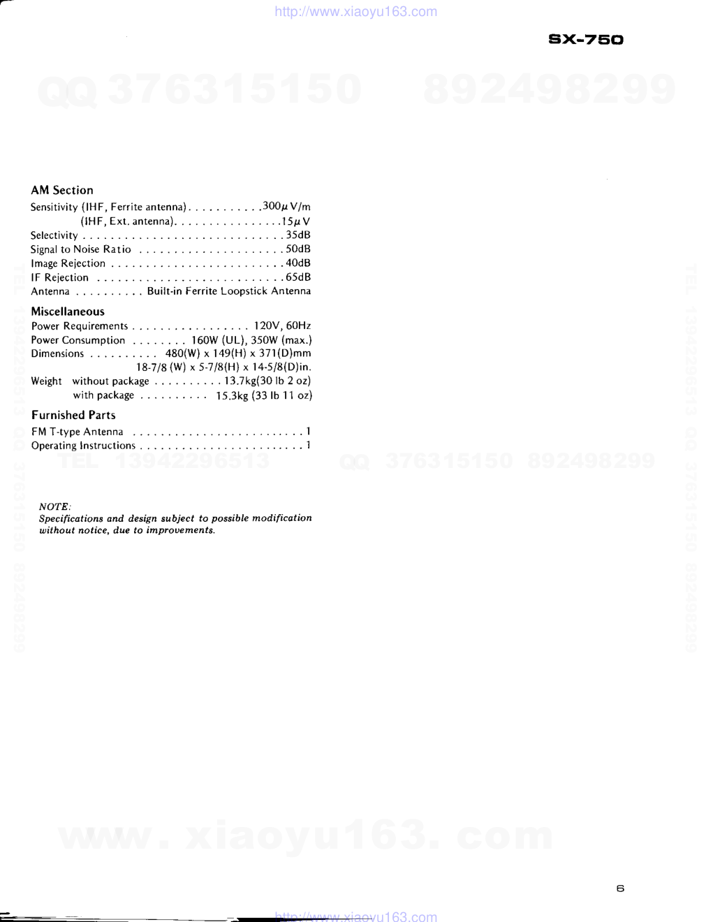
AM Section
Sensilivity
(lH F, Ferrite
antenna).
.
(lH F, Ext. antenna)
Selectivity
S i g n a l
t o N o i s e R a t i o . . . . . .
lmage Reiection
lF Rejection
A n t e n n a
. . . . . . . . . .
B u i l t - i n
. . . . . . 6 5 d B
Ferrite Loopstick
Antenna
. . 13.7kg(30
lb 2 oz)
'l s.3kg (33 lb 1 '1 oz)
.300s V/m
. . . . 1 5 t t V
. . . . 35dB
. . . . 50dB
. . . . 40dB
Miscellaneous
P o w e r R e q u i r e m e n t s . . .
. . . 1 2 0 V , 6 0 H 2
Power
Consumption
160W (UL), 350W (max.)
Dimensions
.. 480(W)
x 149(H)
x 371(D)mm
18-718
(w) x s-7l8(H)
x 14-sl8(D)in.
W e i g h t
w i t h o u t p a c k a g e
. . . . . . . .
with package
Furnished Parts
FN4
T-type Antenna .
Operating Instructions
NOTE:
Specifications and design subject to possible modificotion
without notice, due to improoements.
www. xiaoyu163. com
QQ 376315150
9
9
2
8
9
4
2
9
8
TEL 13942296513
9
9
2
8
9
4
2
9
8
0
5
1
5
1
3
6
7
3
Q
Q
TEL 13942296513 QQ 376315150 892498299
TEL 13942296513 QQ 376315150 892498299
http://www.xiaoyu163.com
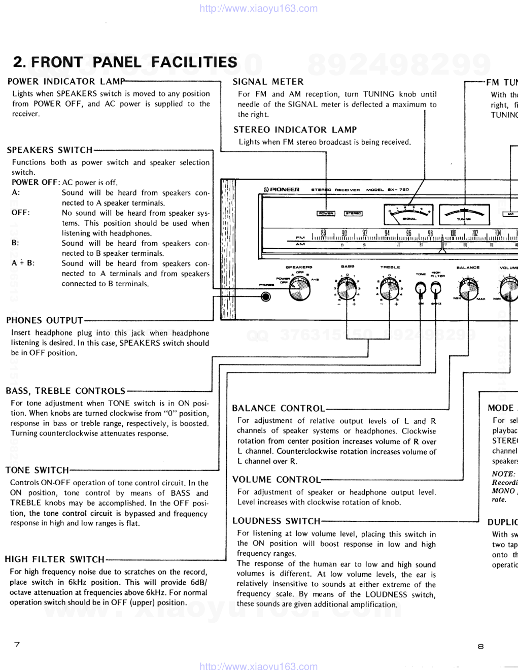
2. FRONT PANEL FACILITIES
POWER INDICATOR LAM
Lights when SPEAKERS switch is moved to any position
from POWER OFF, and AC power is supplied to the
receiver.
SPEAK.ERS
SWITCH
Functions both as power switch and speaker selection
switch.
POWER OFF: AC power is off.
A:
OFF:
B:
A i B :
PHONES
OUTPUT
Insert headphone plug into this jack when headphone
listening
is desired.
In this case,
SPEAKERS
switch should
be in OFF position.
BASS, TREBLE CONTROLS
For tone adjustment when TONE switch is in ON posi-
tion. When knobs are turned clockwise from "0" position,
response in bass or treble range, respectively,
is boosted.
Turning counterclockwise
attenuates
response.
TONE SWITCH
Controls
ON-OFF ooeration
of tone control circuit. ln the
ON position, tone control by means of BASS and
TREBLE knobs may be accomplished.
In the OFF posi-
tion, the tone control circuit is bypassed and frequency
response
in high and low ranges is flat.
HIGH FILTER SWITCH
For high frequency noise due to scratches on the record,
place switch in 6kHz position. This will provide 6dB/
octave attenuation at frequencies
above 6kHz. For normal
operation switch should be in OFF (upper) position.
Sound will be heard from speakers con-
nected to A speaker terminals.
No sound will be heard from speaker sys-
tems. This position should be used when
listening
with headphones.
Sound will be heard from soeakers con-
nected to B speaker terminals.
Sound will be heard from speakers con-
nected to A terminals and from speakers
connected to B terminals.
STEREO INDICATOR LAMP
Lights when FM stereo
broadcast
is being received.
(\D r'IONCGT.
BT
EPEAKEFg
.*
;'l?."
BALANCE CONTROL
For adjustment of relative output levels of L and R
channels of speaker systems or headphones.
Clockwise
rotation from center position increases
volume of R over
L channel. Counterclockwise
rotation increases
volume of
L channel over R.
VOLUME CONTROL,
For adjustment of speaker or headphone
output level.
Level increases
with clockwise rotation of knob-
LOUDNESS
SWITCH
S I G N A L M E T E R
For FM and AM reception,
needle of the SIGNAL meter
the right.
turn TUNING knob until
is deflected
a maximum to
level, placing this switch in
response in low and high
F A L A N C I
FM TU
With th
right, f
T U N I
MOD
For s
playb
STER
chann
speak
NOTE:
Recor
MONO
rate.
D U P L I
With s
two ta
onto t
operat
For listening at low volume
the ON position will boost
frequency ranges.
The response of the human ear to low and high sound
volumes is different. At low volume levels, the ear is
relatively insensitive to sounds at either extreme of the
frequency scale. By means of the LOUDNESS switch,
these sounds are given additional amplification.
l
u
u
t
J
F M
l i l l m i l i l l r i l '
AM
55
, $ ? , 9 4 , 9 6 , 0 g , 1 0 0 , 1 0
i l l i l r l t l | l t l i l l t ] r I r l i l t t l i l t t l i l t l | i l t r n , t r t t i l i l l i t i l t i l t l
www. xiaoyu163. com
QQ 376315150
9
9
2
8
9
4
2
9
8
TEL 13942296513
9
9
2
8
9
4
2
9
8
0
5
1
5
1
3
6
7
3
Q
Q
TEL 13942296513 QQ 376315150 892498299
TEL 13942296513 QQ 376315150 892498299
http://www.xiaoyu163.com
ii.
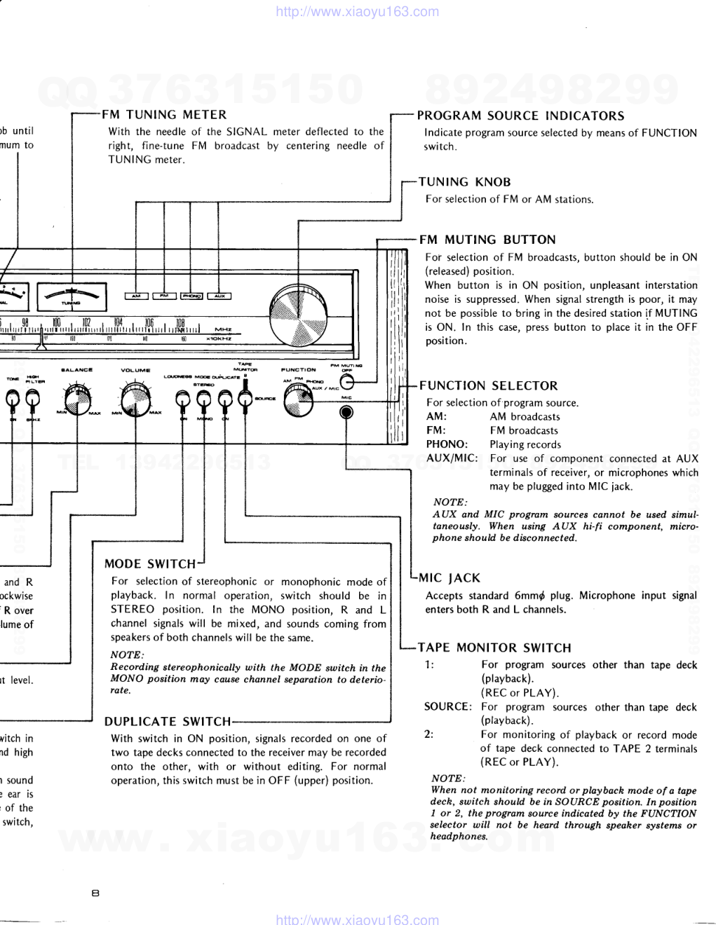
F M T U N I N G M E T E R
With the needle of the SIGNAL meter deflected to the
right, fine-tune FM broadcast by centering needle of
TUNING meter.
PROGRAM SOURCE INDICATORS
Indicate program source selected by means of FUNCTION
switch.
TUNING KNOB
For selection
of FM or AM stations.
FM MUTING BUTTON
Foi selection of FM broadcasts,
button should be in ON
(released)
position.
When button is in ON position, unpleasant interstation
noise is suppressed.
When signal strength is poor, it may
not be possible
to bring in the desired
station if MUTING
is ON. In this case, press button to place it in the OFF
position.
FUNCTION SELECTOR
For selection of program source.
AM:
FM:
AM broadcasts
FM broadcasts
PHONO:
Playing
records
AUX/MIC: For use of component connected at AUX
terminals of receiver, or microphones
which
may be plugged
into Mlc jack.
NOTE:
AUX and MIC program sources cannot be used simul-
taneously. When using AUX hi-fi component, micro-
phone should be dbconnected.
rc JAcK
Accepts standard 6mm{ plug. Microphone input signal
enters both R and L channels.
TAPE MONITOR SWITCH
1:
For program sources other than tape deck
(playback).
(REC or PLAY).
SOURCE: For program sources other than tape deck
(playback).
2:
For monitoring of playback or record mode
of tape deck connected to TAPE 2 terminals
(REC or PLAY).
NOTE:
When not monitoring record or playback mode of a tape
dech, switch should be in SOURCE position. In position
1 or 2, the program source indicated by the FUNCTION
selector will not be heard through speaher sysfems or
headphones.
i',,1
,, , t
* ;s-
and R
ockwise
' R over
lume of
rt level.
vitch in
nd high
l sound
3 ear is
r of the
switch,
to*s
ueoiwer:
!
MODE SWITCH
For selection of stereophonic or monophonic mode of
playback. In normal operation, switch should be in
STEREO position. In the MONO position, R and L
channel signals will be mixed, and sounds coming from
speakers
of both channels will be the same.
NOTE:
Recording stereophonically with the MODE switch in the
MONO position may cause channel separation to deterio-
rate.
DUPLICATE
SWITCH
With switch in ON position, signals recorded on one of
two tape decks connected to the receiver may be recorded
onto the other, with or without editing. For normal
operation,
this switch must be in OFF (upper) position.
a
l i l l l l l l l l l l l r l l l l
www. xiaoyu163. com
QQ 376315150
9
9
2
8
9
4
2
9
8
TEL 13942296513
9
9
2
8
9
4
2
9
8
0
5
1
5
1
3
6
7
3
Q
Q
TEL 13942296513 QQ 376315150 892498299
TEL 13942296513 QQ 376315150 892498299
http://www.xiaoyu163.com
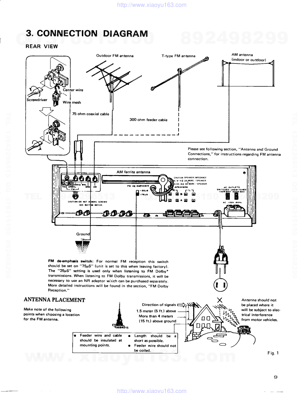
3. CONNECTION DIAGRAM
REAR VIEW
Outdoor FM antenna
Center wire
- t l
mesh
75 ohm coaxial cable
{indoor or outdoorl
k
A*ry
ANTENNA PLACEMENT
Make note ot rhe lollowing
po'nts when choosing e location
for the FM antenna.
300 ohm leeder cable
Direction ot signals
1.5 meter (5 ft.) above
More than 4 meters
(15 ft.) above ground
Please see tollowing section, "Antenna and Ground
Connections," for instructions regarding Fl/1 antenna
FM do-rmph6i5
3witch:
For normal FM recebtion rhis switch
shorrld be set on "75!S" (unir is set to rhis when leaving factory).
The "25pS"
setting is used only when listening to FM Dolby*
transmissaons.
When listening ro FM Dotby transmissions, it wi be
necessary lo use an NR adaptor wiich can be purchased separately.
More detailed instructions witt be found in the section, ,,FM Dotbv
Reception."
Antenna should not
tte placed where it
will be subiect to elec-
tracal interlerence
from motor vehicles.
Fig. I
s
r L _ t
6 E
E
B E ^ A t r
Feeder wire and cSle
a
Length
should
b€ a
should be insulated at
short as possible.
mounting points,
a
Feeder wire should not
b€ coiled.
www. xiaoyu163. com
QQ 376315150
9
9
2
8
9
4
2
9
8
TEL 13942296513
9
9
2
8
9
4
2
9
8
0
5
1
5
1
3
6
7
3
Q
Q
TEL 13942296513 QQ 376315150 892498299
TEL 13942296513 QQ 376315150 892498299
http://www.xiaoyu163.com
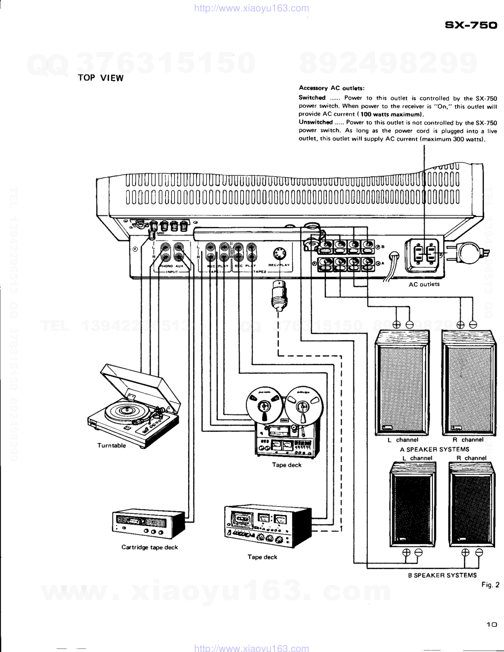
TOP VIEW
six-750
Accessory AC outlets:
Switched ...... Power to this outlet is controtted by the SX-750
pow€r switch. Wh€n power to the receiver is "On," this oudet will
provide AC currenr { 10O watts maxamuml.
Unslvitchod..... Power to this outlet is not controtted by the SX,75O
power swilch. As long as the power cord is plugged into a tive
outlet, this outlet will supply AC current {maximum 300 warts).
AC outl€ts
L channel
R chr
A SPEAKER SYSTEMS
L channel
m
R channel
m
0000
0 0
000000
00[| 0 0 000
000
rt000000000000000000000000
B SPEAKER SYSTEMS
Carrridg€ tape deck
Tape deck
Fig.2
www. xiaoyu163. com
QQ 376315150
9
9
2
8
9
4
2
9
8
TEL 13942296513
9
9
2
8
9
4
2
9
8
0
5
1
5
1
3
6
7
3
Q
Q
TEL 13942296513 QQ 376315150 892498299
TEL 13942296513 QQ 376315150 892498299
http://www.xiaoyu163.com
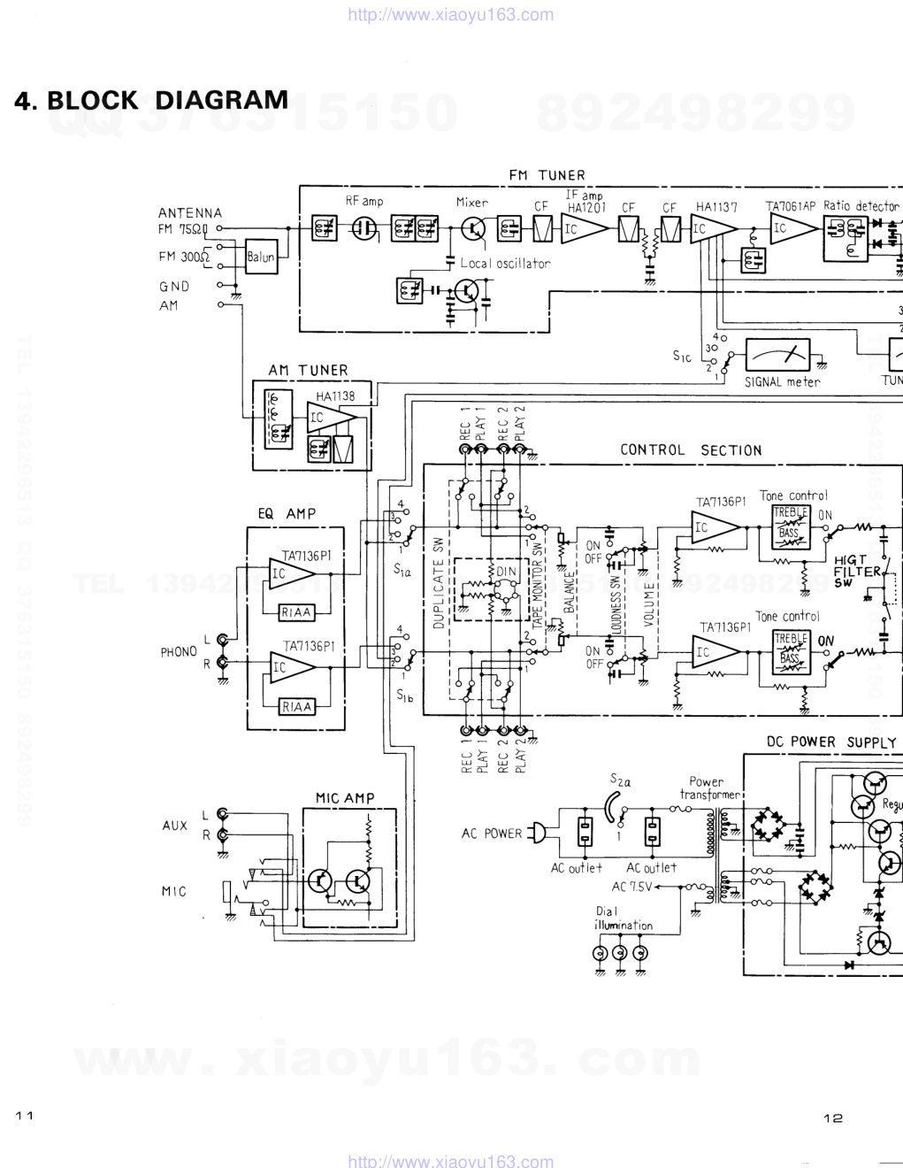
4. BLOCK DIAGRAM
A N T E N N A
FI1 TSQ
FM 300si
G N D
Af1
I F a m p
C F . H A 1 2 O 1 C F
H A l 1 3 ?
T410614P
Ratio detecf
SIGNAL
meter^
v l u
CONTROL SECTION
TAl136P1
TAl 1 36Pi
A 1 1 T U N E R
*,;t-l
A M P
TA1136Pl
!
IlIC AH P
c!
c!
3 5
Tone control
ON
EQt--
rF
,#
{rr
=
U)(./)
(-/)
p-.
a
ON
OFF
I
I
I
I
I
I
I
I
I
=
U)
IY
P
=
=
t-rl
o_
g
1
-l
I
I
I
I
I
J
7
I
L
PHONO
R
L
A U X nK
tl lc
0 N 6 . l
OFF
t
,
16ng gQnTfol
ON
DC POWER SUPPL
,
a
F
: ; - <
( Y h
AC POWER
C\J
C!
, : k
LLJ
_l
q,
D
l
_
'
_
i
FI1 TUNER
rPFRI F
#
bA))
TAl 1 36 P1
I
I
I
t f -
t l
i l ,
i ! t
t l ,
I
I
=
c/)
Lri
-)
o_
f-
IR FR I F
:tV€
J}}L
_--5.
Local oscillafor^
@g
l--
f,tr
i
_ ;
H i
oa o-
+
3O
2"
1
1
S r o
AC outlet
AC ouilet
AC ].5V
Dia I
illunrination
www. xiaoyu163. com
QQ 376315150
9
9
2
8
9
4
2
9
8
TEL 13942296513
9
9
2
8
9
4
2
9
8
0
5
1
5
1
3
6
7
3
Q
Q
TEL 13942296513 QQ 376315150 892498299
TEL 13942296513 QQ 376315150 892498299
http://www.xiaoyu163.com
T4T0614p
Ratio detecton
NPX decoder
HA'I136
0FFo
fM l4uLiny
T7V
4 o
.
3 o
) 1 d
SIGNAL
meten
TUNING meter
FM MUI NG
i_
STERE0
indicaton
,-l
+13V
i
ONl
I
k
srs
5-I
ej'
TION
POW
ER AIl P
+ 4 1 V
- + 1 v
+ 1 3 V
*3 5V
- 38V
PROTECTION
CIRCUIT
AC'I.5V
Tone contr-ol
ON
Tone controi
ON
-ll--
! i
SUPPLY
Hrqr I
FlLTERy'..-,
s w r i it
l
ftsl2yidnive
Sze
q- -
V Z U
Szu
Over-ourr^ent !
over- I oad
I
detec-fion
_-J
DC POWER
Pro X ram
indicator^
eLo
2 o o
5e
1 l
I
n
I
L _ _ R
PHONES
SPEAKERS
nK
Sr ' FUNCTI0N
switch
Sz , SPEAKERS
switch
1 . A I . 1
1 . P O W E R
O F F
2 . F M
2 , A
3 P H O N O
3 . O F F
4. AUX/Y|C
4. B
5 . A + B
A M
r M
l - l l
PHONO
AUX
' b 6
ob
A
)-
5
Powen
indicaion
ReXu
lator'
S r e
www. xiaoyu163. com
QQ 376315150
9
9
2
8
9
4
2
9
8
TEL 13942296513
9
9
2
8
9
4
2
9
8
0
5
1
5
1
3
6
7
3
Q
Q
TEL 13942296513 QQ 376315150 892498299
TEL 13942296513 QQ 376315150 892498299
http://www.xiaoyu163.com
5. CIRCUIT DESCRIPTIONS
5.1 AM TUNER
Composed of single IC (HA1138) combining a 1
stage RF amplifier and a 2 stage IF amplifier (Fig.
1).
5.2 FM TUNER
Front End
The outstanding performance, exemplified by the
remarkable 80dB imaging and 90dB
spurious
rejection, originates in the dual-gate MOS FET
RF amplifier and 4-gurg variable capacitor tuning
circuit. A modified Clapp circuit is employed in
the local oscillator, leading to high frequency
stability. Since the output
is taken from the
oscillator tuning circuit, higher harmonics in the
oscillator signal and spurious response become
reduced.
sx-750
lF Amplifier and Detector
Comprise 2 dual element ceramic filters,
sistor, and 1 IC (integrated circuit).
(HA1137) circuit is illustrated in Fig. 2.
FM lF Amplifier and Detector Circuit
Three dual element ceramic filters, an IC (HA1201)
containing a differential
amplifier, and an IC
(HA1137) containing a 3-stage limiter amplifier
compose the FM IF amplifier. Fig. 2 shows the
HA1137 block diagram (see circuit diagram on
page 65).
In addition to limiter amplifier. the HA1137 IC
includes detector, meter drive circuits. The detec-
tor circuit in the HA1137 is not employed in this
set however a separate ratio detector circuit is
employed instead, resulting in improved S.N ratio.
1 tran-
The IC
Fig. 1 Block Diagram of HA1 138
Fig.2 Block Diagram
of HA1137
1 3
www. xiaoyu163. com
QQ 376315150
9
9
2
8
9
4
2
9
8
TEL 13942296513
9
9
2
8
9
4
2
9
8
0
5
1
5
1
3
6
7
3
Q
Q
TEL 13942296513 QQ 376315150 892498299
TEL 13942296513 QQ 376315150 892498299
http://www.xiaoyu163.com
Multiplex Decoder
Demodulation is performed by switching detection.
A single IC (HA1196) composes the circuit, which
is divided into 3 sections. Fig. 3 shows the HA1196
block diagtam (see circuit diagram on page 65).
1. Switching signal generator
A PPL (phase locked loop) system is employed.
76kHz is generated by a VCO (voltage controlled
oscillator: oscillator in which the frequency is
varied by a control voltage) and converted into
19kHz by a frequency divider. This signal and
the pilot (19kHz) of the received signal are
applied to a phase comparator, which converts
the phase differences of the two signals into a
voltage. The voltage is then fed back to the VCO.
The oscillator signal phase becomes locked to
the pilot signal by this loop (PLL) and a 38kHz
signal synchronised to the pilot signal is obtained
and employed as the switching signal.
2. Automatic stereo detector
With the PLL locked to the pilot signal, the pilot
signal and a 19kHz signal of the same phase are
produced. A voltage is then obtained at the
phase comparator that is proportional to the
pilot signal amplitude. As it increases, the lamp
lights and the switch becomes on. The switching
signal is applied to the demodulator.
3. Demodulator
This is a switching circuit employing two dif-
ferential amplifiers (Fig. a). Q1 and Q2 are
altemately switched on and off by the switch-
Com0osit
siFel
ing signal. The composite signal is amplified at
Q3, switched and demodulated. Q6 and QB are
Ioosely coupled at their emitters by R1 - R3.
QG is driven in reverse phase to Q3. This is
switched at Q4 and Q5, and by composing with
Q1 and Q2 at the collector, crosstalk becomes
cancelled.
Adequate current flow is required to QB and
Q6 to improve distortion figures at this point.
However, if the base bias voltage is raised, the
voltage component at the collector becomes
reduced and clipping occurs (power supply
voltage is limited by IC voltage endurance).
For this reason, current from an external source
is inserted at Q3 and Q6 collectors to become
11 and Ir. The same current amounts are ob-
tained as 13 and Ia from the emitters. Q3 and
Q6 therefore operate with adequate current,
and distortion
at this stage becomes remark-
ablly improved. A feedback amplifi.er amplifies
the demodulated output.
Ycc
Switching
signal(38tl|r)-*
Com0osite
signal
Fig. 4 Equivalent
Circuit of Demodulator
Af am!.
Phasc
conlaratol
1 4
Fig. 3 Block Diagram of HA1196
www. xiaoyu163. com
QQ 376315150
9
9
2
8
9
4
2
9
8
TEL 13942296513
9
9
2
8
9
4
2
9
8
0
5
1
5
1
3
6
7
3
Q
Q
TEL 13942296513 QQ 376315150 892498299
TEL 13942296513 QQ 376315150 892498299
http://www.xiaoyu163.com
5.3 FM MUTING CIRCUIT
At time of detuning (more than t 70kHz) and with
an antenna input of less than 10dB (OdB = 1pV), a
DC voltage is produced at pin 12 of IC, (HAl137).
This voltage is employed as the muting trigger.
With the MUTING switch ON, Q1 becomes ON
and Q2 OFF in the Q1-{2
Schmitt circuit as the
muting trigger is produced. Q3 becomes ON when
Q2 is OFF, and Q4, Q5 and Q6 also become ON.
With q4 & Qb ON, the FM output becomes
grounded, while IC, output is grounded by Q6 to
apply muting.
Fig. 5 FM Muting Circuit
5.4 PHONO EOUALIZER AMPLIFIER
IC (TA7136P1) is used with independent left and
right channels. Grade G styrole capacitors and
grade F metal film resistors comprise the equal-
izer elements, leading to an RIAA
deviation
within 0.2dB from 30Hz to 15kHz.
sx-75Cl
5.5 MICROPHONE
CIRCUIT
A 2 stage transistor amplifier (monophonic) is
provided in addition to the phono equalizer ampli-
fier. A selector switch cuts the AUX jack input
when a plug is inserted into the MIC jack. The
amplified microphone signal is then supplied to
both the left and right channels. The FUNCTION
switch is set to the AUX position when using a
microphone.
Function SW
. B
Lch
AUX
Fis. 7
5.6 TONE CONTROL
CR type tone controls are connected to an ex-
tremely low
output impedance flat applifier
(IC = T47136, 31dB gain). Bass can be varied in
the range of +343 - -7dB (100H2) and treble in
the range of +943 - - 7dB (10kHz). A TONE
switch also allows the tone controls to be switch
ON/OFF.
R1 and R2 arc designed to provide the same loss
when the TONE switch is OFF as obtained with
the TONE switch ON and the BASS and TREBLE
controls at center positions (flat). Frequency
response thus becomes flat when the TONE
switch is set to OFF.
R3, and Cl form a 6kHz 6dB/octave HIGH CUT
filter which is connected following the TONE
switch.
Fig. 6
F i s . 8
4 E
FurLction 5V
TA''t136P-r
TA'r | 36
www. xiaoyu163. com
QQ 376315150
9
9
2
8
9
4
2
9
8
TEL 13942296513
9
9
2
8
9
4
2
9
8
0
5
1
5
1
3
6
7
3
Q
Q
TEL 13942296513 QQ 376315150 892498299
TEL 13942296513 QQ 376315150 892498299
http://www.xiaoyu163.com
5.7 PROTECTION CIRCUIT
This protection circuit functions to protect the
speakers and the power amplifiers from damage
due to short-circuit of the load, etc., and performs
a muting operation to cut noise and distortion
which occur when switching the power on and off.
The circuit is shown in Fig. 15, and consists of a
bridge type over-current and overload detector, a
differential amplifier DC voltage detector, and a
power switch ON/OFF detector section.
Relay Driving Circuit
Q4-Q6,
in Fig. 9, comprise the relay driving
circuit.
In the normal condition reverse bias is applied to
the base of Q4, and Q4 is in a off state. When
one of the above mentioned detection circuits
goes or, current flows through R11, the base
potential falls and Q4 is turned on. Consequently
Qb comes on and Q6 goes off. When Q6 goes off,
the current of the relay circuit is cut, to release
the switch of the output circuit.
When the power switch is turned on, a delay
operation occurs in this circuit. R17 and C3, in the
base circuit of Q6, are the time constant elements
which determine the delay time. When the power
switch is tumed on, C3 charges to a potential of
+60 volts through R17 and R18, and Q6 is kept in
the off state during this time. When the power
source is switched off, the muting operation of Qb
prevents shock noise. In the normal condition, the
potentials of +33 volts and - 5.1 volts are applied
to Qb through RL4 and R15. The resultant poten-
tial at the base of Q5 is -1 volt in the cutout
condition. When the power supply is turned off,
PoY|er
amplifier
0Yer-current
and
overload
detection
circuit
of - 5.1 volts disappears immediately due to the
small time constant of the power circuit. Thus a
positive base potential remains, switching Qb on,
which in turn switches off Q6 and hence the relay.
Detection of DC Voltage
This is a differential amplifier consisting of Q2
and Q3, as shown in Fig. 10. The bases of Q2
and Q3 are connected to the center points of the
right and the left power amplifiers. When the
DC balance of the power stage is lost for some
r€ason, a potential difference is produced in the
input signal to the differential amplifier, and the
collector currents of Q2 and Q3 are put out of
balance. Ttrus, the relay driving circuit functions,
and the relay switch is tumed off.
t r - - - - - - - l
+ B
I c h
R u R - n
-fiRelaydriring
ci rcuit
R c h
n
0 ,
Iv-
It'
0 "
\ "
R r o
B
L - - - - _
- - l
Fig. 10 DC Voltage Detection Circuit
RelaY
-arl
f t l
Power
amplilier
IlC vultage
detectioll
circuit
*Y"l
I
I
Retay driving circuit
o , I
R 6
c " )
Fig. 9 Protection Circuit
www. xiaoyu163. com
QQ 376315150
9
9
2
8
9
4
2
9
8
TEL 13942296513
9
9
2
8
9
4
2
9
8
0
5
1
5
1
3
6
7
3
Q
Q
TEL 13942296513 QQ 376315150 892498299
TEL 13942296513 QQ 376315150 892498299
http://www.xiaoyu163.com
f,
Over-current and Overload Detection
The equivalent circuit of this detector section is
shown in Fig. 11, and Fig. L2-a shows the equiva-
lent circuit at the time of a positive half cycle.
When this equivalent circuit is overloaded, the
balance of the bridge, formed by RE1, R1, Rg
and RL, is disturbed, and a potential is produced
between b and a in such a direction that Q1 is
turned on. When Ql is turned on, the collector
current increases, the relay driving circuit functions
and the relay switch of the output circuit is
turned off.
After the cause of the overload is removed, the
bias of Ql is reduced and the relay switch turns on
to automatically restore normal operation, Fig. 18-b
shows the equivalent circuit at the time of a
negative half cycle. In this circuit, a potential is
produced between b and e as above, and Q1 is
tumed on.
Powsr
amplilier
+ Vcc
Fig. 11 Over-current
and Overload Detection Circuit
FiS. 12 Equivalent
Circuit of
sx-75cl
5.8 POWER AMPLIFIER CIRCUIT
Composed of differential first stage, all stages
direct coupled pure complementary OCL circuit.
Open gain at lkHz is approximately 80dB and
NFB amount is approximately 50dB. R3 and R4
are provided with this circuit in order to obtain
adequate stability even with the NFB disconnected.
Ql form a differential amplifier LOOVo d.c. feed-
back is applied from the junction point of the
power stage to the base of Q1 so the potential of
the junction point is always maintained at the
same level.
Fis. 13
5.9 POWER SUPPLY
Two windings are provided in the power trans-
former secondary and each is separately bridge
rectified. One of these is sent as 148 VDC to the
voltage stabilizer circuit to become 13V, 33V
and -37V regulated voltages for supply to each
assembly.
The other secondary voltage is bridge rectified and
becomes t 4IV or supply to the power amplifier
predriver stage. Extremely low power supply
impedance is maintained by a 15,000pF electro-
lytic capacitor.
1 7
www. xiaoyu163. com
QQ 376315150
9
9
2
8
9
4
2
9
8
TEL 13942296513
9
9
2
8
9
4
2
9
8
0
5
1
5
1
3
6
7
3
Q
Q
TEL 13942296513 QQ 376315150 892498299
TEL 13942296513 QQ 376315150 892498299
http://www.xiaoyu163.com
6. ADJUSTMENTS
6.1. AM SECTTON
1. Set function switch to AM.
2. Connect AM signal generator through lk-ohm
resistor to AM antenna terminal.
3. Set DUPLICATE switch to OFF and connect
an AC voltmeter to TAPE 1 REC jacks.
4. Set AM SG for 4O0Hz 30% modulation 74dB
output.
5. Set SX-750 dial indication and AM SG fre-
quency for 600kHz.
6. Adjust T8 core for maximum reading on AC
voltmeter.
7. Set SX-750 dial indication and AM SG fre-
quency for 1,400kH2.
8. Adjust TCz for maximum reading on AC
voltmeter.
9. Set AM SG for 30dB output.
10. Set SX-750 dial indication and AM SG fre-
quency for 600kHz.
11. Adjust T8 and bar antenna core for maximum
reading on AC voltmeter.
12. Set SX-750 dial indication and AM SG fre-
quency for 1,400kH2.
13. Adjust TCz, TC4 for maximum reading on AC
voltmeter.
14. Repeat steps 10-13 to eliminate variations in
AC voltmeter readings.
AM signal generator
Fig. 14
1 E l
www. xiaoyu163. com
QQ 376315150
9
9
2
8
9
4
2
9
8
TEL 13942296513
9
9
2
8
9
4
2
9
8
0
5
1
5
1
3
6
7
3
Q
Q
TEL 13942296513 QQ 376315150 892498299
TEL 13942296513 QQ 376315150 892498299
http://www.xiaoyu163.com
I
6.2 FM SECTION
FM Trac(ing
1. Connect measuring equipment as shown in
Fig. 15.
2. Set FM SG to lO|Vo modulation (x7lkHz
deviation) at 4OOHz and 100dB output.
3. On SX-750 front panel, set FM switch to ON,
FM muting to OFF and VOLUME control to
minimum position.
4. Set TC6 to center of turning range.
5. T\rne FM SG and SX-Z5O to dial readings of
9OMHz.
6. Adjust T4 core for maximum indication on
Signal meter.
7. Adjust T6 core for center of scale indication on
Tuning meter.
8. Set FM SG output to 8- 10dB and adjust cores
of T1, T2, and T3 for maximum indication on
Signal meter.
9. Ttrne FM SG and SX-250 to dial readings of
106MHz.
10. Set FM SG output to 100dB and adjust TC6
for muimum
indication on Signal meter.
11. Set FM SG output to 8-10dB and adjust TC1,
TC3. TC5 and TC6 for maximum indication on
Signal meter.
12. Repeat above adjustment steps 5 - 11 and
adjust for optimum conditions.
13. Tune FM SG and SX-750 to dial readings of
90MHz.
14. Adjust T5 core for maximum indication on
Signal meter.
L5. Detune SX-750 (to noise only).
16. Adjust T6 for center of scale indication on
Tuning meter.
17. Tune FM SG and SX-750 to dial readings of
98MHz.
18. Set FM SG output to 60dB and adjust upper
core of T7 for maximum reading on AC volt-
meter.
19. Adjust lower core of T7 for minimum audio
frequency output distortion.
20. Set FM SG for 100dB output and adjust VR1
so that Signal meter indicates 5 of the scale.
AC voltmeter Distortion meter
FM. SG
FM signal generator
Fig. 15
www. xiaoyu163. com
QQ 376315150
9
9
2
8
9
4
2
9
8
TEL 13942296513
9
9
2
8
9
4
2
9
8
0
5
1
5
1
3
6
7
3
Q
Q
TEL 13942296513 QQ 376315150 892498299
TEL 13942296513 QQ 376315150 892498299
http://www.xiaoyu163.com
6.3 MPX Adjustment
1. Oonnect measuring equipment as shown in
Fig.16.
2. T\rne FM SG and SX-750 to dial readings of
98MHz.
3. Set FM SG for 60dB unmodulated output.
4. Connect the output signal (19kHz) of MPX SG
PILOT OUT terminal to the horizontal input of
an oscilloscope, and pin 20 of the tuner assembly
(AWE-073) via a probe to the oscilloscope
vertical input.
5. Adjust VR2 so that lissajous pattern displayed
on oscilloscope becomes stationary (Fig. 16).
6. Set MPX SG to 67.5kHz deviation at lkHz for
left and right channels, and to 7 .1kHz deviation
for 19kHz pilot signal.
7. Adjust T5 core for minimurn audio frequency
distortion. Take care to turn core only within
t180'.
8. Adju.st VR3 for minimum signal leakage from R
channel to L channel, and from L channel to
R channel.
OscilloscoPe
Lissajous
AC voltmeter Distortion meter
" [ E m
, /
|
1 V
Fis. 16
www. xiaoyu163. com
QQ 376315150
9
9
2
8
9
4
2
9
8
TEL 13942296513
9
9
2
8
9
4
2
9
8
0
5
1
5
1
3
6
7
3
Q
Q
TEL 13942296513 QQ 376315150 892498299
TEL 13942296513 QQ 376315150 892498299
http://www.xiaoyu163.com
6.4 POWER AMPLIFIER SECTION
ldle Current Adjustment
1. Connect DC voltmeter as shown in Fig. 17.
2. Do not connect load to speaker terminals. Set
VOLUME control to minimum (fully counter-
clockwise).
3. Turn VRl and VR2 (shown in Fig. 17) fully
counter-clockwise, then set POWER switch to
oN.
4.1- 2 minutes after tuming on the power, adjust
VR3 (L channel) and VR4 (R channel) for
50mV indication on DC voltmeter.
5. 20 minutes after turning on the power, again
adjust VR1 and VR2 for 30mV indication on
DC voltmeter.
Eix-7E'cl
F i g . 1 7
2 1
www. xiaoyu163. com
QQ 376315150
9
9
2
8
9
4
2
9
8
TEL 13942296513
9
9
2
8
9
4
2
9
8
0
5
1
5
1
3
6
7
3
Q
Q
TEL 13942296513 QQ 376315150 892498299
TEL 13942296513 QQ 376315150 892498299
http://www.xiaoyu163.com
7.DIAL CORD STRINGING
1. Remove the wooden cover and the front panel.
2. Turn tuning drum fully clockwise (as viewed
from X direction in Fig. 18).
3. Tie one end of cord to stud on inner section of
tuning drum (more easily performed by loos-
ening setscrew and temporarily removing tuning
drum from shaft).
4. Route cord through tuning drum cutout, make a
half tum around the drum, then route in
sequence to pulley A-dial
pointer-pulley
B-
pulley C.
5. Wind cord 3 tums clockwise (as viewed from
rear panel) around tuning shaft, then route to
pulley D.
6. Wind cord two tums around tuning drum and
tie to spring hook so that tension is applied to
the cord.
7. Turn TUNING knob and confirm normal cord
motion, then trim off excess cord.
8. With tuning drum at step 1 setting, restrain cord
from moving and slip dial pointer on cord. Align
it with the starting point (extrenne left end of
frequency scale).
Dial pulley
Dial shaft
Dial Pointer Installation Caution
Metal portion of dial pointer is plated. If this
section is touched directly by hand or fingerprints
and other impurities,
it is diffrcult
to remove
dirt from aventurine finish. As this is not desirable
in terms of both appearance and anticorrosion,
take extreme care not to touch t,Le metal section
when handling the dlal pointer.
Dial pointer
Fis. 18
www. xiaoyu163. com
QQ 376315150
9
9
2
8
9
4
2
9
8
TEL 13942296513
9
9
2
8
9
4
2
9
8
0
5
1
5
1
3
6
7
3
Q
Q
TEL 13942296513 QQ 376315150 892498299
TEL 13942296513 QQ 376315150 892498299
http://www.xiaoyu163.com
8. LEVEL DIAGRAM
*{
Power
amp
21.5V(
8Q
2.5mV
( PH0N0)
23
www. xiaoyu163. com
QQ 376315150
9
9
2
8
9
4
2
9
8
TEL 13942296513
9
9
2
8
9
4
2
9
8
0
5
1
5
1
3
6
7
3
Q
Q
TEL 13942296513 QQ 376315150 892498299
TEL 13942296513 QQ 376315150 892498299
http://www.xiaoyu163.com
9. DISASSEMBLY
Top Cover (Fig. 19)
Take out 2 screws each at left and right (total 4
screws) to remove.
Bottom p161s (Fig.20)
Take out screws e- @ to remove.
Front Panel (Fig. 21)
Pull off all knobs and remove shaft nuts of SPEAK-
ERS and FUNCTION switches. Front panel can
then be removed by taking out screws @ & @.
six-7scl
Fis. 19
Fis. 20
Fig.21
{=7?X
24
www. xiaoyu163. com
QQ 376315150
9
9
2
8
9
4
2
9
8
TEL 13942296513
9
9
2
8
9
4
2
9
8
0
5
1
5
1
3
6
7
3
Q
Q
TEL 13942296513 QQ 376315150 892498299
TEL 13942296513 QQ 376315150 892498299
http://www.xiaoyu163.com
lO.PARTS LOCATION
10.1 FRONT
PANEL VIEW
Phone lack (Head phone)
AKN.OlO
Knob (SPEAKERS) -.
AAB.l OO
Front panel assembly
ANB.421
Knob (TONE)
AAD.OI3
Knob (HIGH FILTEF)
AAD.O13
Knob (BASS) - --r
AAB.O99
Knob (TREBLE)
AAB.G'9
Knob (BALANCE) -'--.---i
AAB.O99
www. xiaoyu163. com
QQ 376315150
9
9
2
8
9
4
2
9
8
TEL 13942296513
9
9
2
8
9
4
2
9
8
0
5
1
5
1
3
6
7
3
Q
Q
TEL 13942296513 QQ 376315150 892498299
TEL 13942296513 QQ 376315150 892498299
http://www.xiaoyu163.com
(TUNING}
Aii{A.036
iack (MlC)
AKN.O13
Knob (FUNCTION)
AAB.lOO
(TAPE MONITOR}
(FM MUTING}
AAD.112
AAD-OI3
(DUPLICATE}
AAD.O13
(MODEI
AAD-O13
(LOUDNESS}
www. xiaoyu163. com
QQ 376315150
9
9
2
8
9
4
2
9
8
TEL 13942296513
9
9
2
8
9
4
2
9
8
0
5
1
5
1
3
6
7
3
Q
Q
TEL 13942296513 QQ 376315150 892498299
TEL 13942296513 QQ 376315150 892498299
http://www.xiaoyu163.com
10.2
FRONT PANEL VIEW (with removed Front panel)
I N D I C A T O R
AEC.241 (POWE
R, STER EO)
l N
A
Double meter
AAW,O4O
Dial pointer assembly
AAF.O48
{I
Fhone jack (Headphones)
A K N - O 1 O
Rorary switch (sPEA K E RS)
ASA.O38
Lever switch {TONE)
ASK-09O
L e v e r
s w i t c h ( H I G H F I I T E R )
ASK.090
Variable
resistor
(BASS)
ACV 1 38
Variable
resistor
(TREBLE)
A C V . 1 3 8
Variable
resistor
(BALANCE)
A C V - 1 3 5
www. xiaoyu163. com
QQ 376315150
9
9
2
8
9
4
2
9
8
TEL 13942296513
9
9
2
8
9
4
2
9
8
0
5
1
5
1
3
6
7
3
Q
Q
TEL 13942296513 QQ 376315150 892498299
TEL 13942296513 QQ 376315150 892498299
http://www.xiaoyu163.com
sx-7='ct
INDICATOR (AI\4,
AE C.255
FM, PHONO, AUX)
meter
40
Shaft cover
AEC 254
Tun ing shaft
AXA.124
assemDty
Knob {FlM l\4UTlNG)
A A D . l 1 2
JK'I
!
t
Phone jack (MlC)
A K N , 0 1 3
Rotary switch (F uN cTloN )
ASD.O49
Lever switch (TAPE l\,lON
ITOR)
A S K - 1 0 2
Lever switch (DUPLTCATE)
ASK.092
Lever switch (l\4O
D E )
ASK.09O
Lever switch iLouDN ESS)
ASK.09O
Variable
resistor
(VOLUI\,1E)
A C V . 1 7 9
:)
BALANCE)www. xiaoyu163. com
QQ 376315150
9
9
2
8
9
4
2
9
8
TEL 13942296513
9
9
2
8
9
4
2
9
8
0
5
1
5
1
3
6
7
3
Q
Q
TEL 13942296513 QQ 376315150 892498299
TEL 13942296513 QQ 376315150 892498299
http://www.xiaoyu163.com
10.3 TOP VIEW
Power amplif ier assembly
AWH,O46
Power supply & Protection assembly
AWR.O99
Power transfomer
4TT-264 (Ku model)
ATT'301 (KC model)
E lectrolytic capacitor
ACH,057
Pu lly
A E C . 1 5 3
Lamp assembly
AE L.060
Acrylic board
A E C 2 5 1
Lamp as
AE L-06
www. xiaoyu163. com
QQ 376315150
9
9
2
8
9
4
2
9
8
TEL 13942296513
9
9
2
8
9
4
2
9
8
0
5
1
5
1
3
6
7
3
Q
Q
TEL 13942296513 QQ 376315150 892498299
TEL 13942296513 QQ 376315150 892498299
http://www.xiaoyu163.com
Tuner, AF, & control assembly
AWE.O73
:r..t
$
lf'. I
ffh
't-:
-
;l
t
qt,r,,
. - ' - - - + . \
Tun ing drum assembly
AXA-O7O
Filter & muting assemtlly
AWtvt.094
Tuning shaft assembly
A X A . 1 2 4
Lamp assemllly
AE L,060
Lamp assembly
AE L-06O
ard
www. xiaoyu163. com
QQ 376315150
9
9
2
8
9
4
2
9
8
TEL 13942296513
9
9
2
8
9
4
2
9
8
0
5
1
5
1
3
6
7
3
Q
Q
TEL 13942296513 QQ 376315150 892498299
TEL 13942296513 QQ 376315150 892498299
http://www.xiaoyu163.com
10.4
BOTTOM
\_-l
Tone control assembly
AWG.O46
fir il -l {| Jl
Rotary switch (SPEAKER
)
ASA 038
Cover
Capaciter
a
\
I
Power trans{omer
AIT.264
Power supply assembly
AWR I OO
Power amplif ier assembly
AWH 046
www. xiaoyu163. com
QQ 376315150
9
9
2
8
9
4
2
9
8
TEL 13942296513
9
9
2
8
9
4
2
9
8
0
5
1
5
1
3
6
7
3
Q
Q
TEL 13942296513 QQ 376315150 892498299
TEL 13942296513 QQ 376315150 892498299
http://www.xiaoyu163.com
Tone control assembly
AWG.046
l r - l l l J l h l d $ - l
$ f L l
sx-75c'
Tuner, AF & control assembly
AWE,O73
$''l
Y
I
ft
www. xiaoyu163. com
QQ 376315150
9
9
2
8
9
4
2
9
8
TEL 13942296513
9
9
2
8
9
4
2
9
8
0
5
1
5
1
3
6
7
3
Q
Q
TEL 13942296513 QQ 376315150 892498299
TEL 13942296513 QQ 376315150 892498299
http://www.xiaoyu163.com
10.5 REAR VIEW
Ferrite bar antenna
AXB.OO4
slide switch {DE.E
ASH.0l5
Terminal (ANTENNA)
AKA.OO2
Terminal (INPUT)
AKB-027
Terminal (TAPE 1)
AK8-027
Terminat (TAPE 2)
AKB-027
REC-PB connector socket (5P)
AKP-OO7
www. xiaoyu163. com
QQ 376315150
9
9
2
8
9
4
2
9
8
TEL 13942296513
9
9
2
8
9
4
2
9
8
0
5
1
5
1
3
6
7
3
Q
Q
TEL 13942296513 QQ 376315150 892498299
TEL 13942296513 QQ 376315150 892498299
http://www.xiaoyu163.com
ide s$,ritch
(DE.EMPHASIS)
ASH.015
REC-PB connector socket (5P) ..-.
AKP.OOT
Wooden cabinet
AMM-053
-- AC socket cover
AC power cord
ADG.OO5
Terminal (SPEAKER)
AKE.O29
www. xiaoyu163. com
QQ 376315150
9
9
2
8
9
4
2
9
8
TEL 13942296513
9
9
2
8
9
4
2
9
8
0
5
1
5
1
3
6
7
3
Q
Q
TEL 13942296513 QQ 376315150 892498299
TEL 13942296513 QQ 376315150 892498299
http://www.xiaoyu163.com
1 . EXP LODED VI EW
PART I
on page 37
PART II
on page 38
Screw 3x6
ABA-048
P A R T I I I
on page 39
Electrolytic
ACH-057 _---
Screw
ABAr002
Scr"* 3,.)
ABA.048 -
Scr
AB
\.
t --..-
i
PNRT IV\
on page 40
'1--., n
-^''
Screw
ABA.OO2
Washer lV 1 1
822-009
N u t M 1 1
871.005
Knob (SPEAKERS,
FUNCTION)
AAB-1OO
6
Washer
ANF.453
Knob (BASS, TREBLE, BLANCE)
AAB.099
K;obGASS, TR EB LE, B LANCE)
AAB.O99
J(
A
Front panel assembly
ANB.421
Knob (VOLUME)
AAB-1OO
Knob ITUNING)
AAA-036
Knob (SPEAKERS,
FUNCTTON)
AAB-1OO
Knob (TONE, HIGH FILTER)
AAD.1 13
I I
l
,"r"* *i't\
'
ABA.(X9
www. xiaoyu163. com
QQ 376315150
9
9
2
8
9
4
2
9
8
TEL 13942296513
9
9
2
8
9
4
2
9
8
0
5
1
5
1
3
6
7
3
Q
Q
TEL 13942296513 QQ 376315150 892498299
TEL 13942296513 QQ 376315150 892498299
http://www.xiaoyu163.com
sx-7E'o
PART I II
on page 39
NOTE:
Parts indicated in green type cannot be supplied,
-Wooden cabinet
AMM-053
4x15
1 3
Screw
ABA-OO2
PART VII
on page 43
Screw
ABAi0O2
Screw 4x1
ABA-113
q,
\
Screw
ABA.1
r^
ANB-421
\KE BS. FUNCTION)
FILTER)
Front panel assembly
Screw
ABA-012
Foot
AEC-083
Washer
ANF-453
Screw
ABA.O12
Screw
ABA.O12
Foot
ABA,O12
Screw
ABA-012
AEC-083
www. xiaoyu163. com
QQ 376315150
9
9
2
8
9
4
2
9
8
TEL 13942296513
9
9
2
8
9
4
2
9
8
0
5
1
5
1
3
6
7
3
Q
Q
TEL 13942296513 QQ 376315150 892498299
TEL 13942296513 QQ 376315150 892498299
http://www.xiaoyu163.com
11.1 PART I
NOTE:
Parts indicated in green type cannot be supplied,
Screw 3xB
ABA.066
Acrylic board
AEC-25'l
HT
Dial panel
AAG-l 14
Screw 3x6
ABA-O48 I
Screw 3xo
ABA-048
g
Lamp aisembly
AEL.O6O
Tuning shaft assembly
AXA-124
%
Screw 3x6
ABA.104
Lamp with wire
AEL.O69
Spacer M9xlt
M45-086
. Nut
'a71-004
Screw 3x6
ABA.O48
Lamp holdei
AEB-@O
Lamp with wire
AEL.O68
Lamp with wire
AEL.O66
A
B
c
D
A
c
D
www. xiaoyu163. com
QQ 376315150
9
9
2
8
9
4
2
9
8
TEL 13942296513
9
9
2
8
9
4
2
9
8
0
5
1
5
1
3
6
7
3
Q
Q
TEL 13942296513 QQ 376315150 892498299
TEL 13942296513 QQ 376315150 892498299
http://www.xiaoyu163.com
11.2 PART II
NOTE:
Parts indicated in green type cannot be supplied.
Power transformer
ATT-2O4 (KU model)
ATT-301 (KC model)
Power transformer
mounting holder
Terminal strip (2P)
Nut M4
ABN.O13
Scrarv 3xG
ABA-048 Fuse holder (1P)
P)
AKR-(F2
Screw 3x6
- G r , r L r n , l
t e r r r n u l ( 4 P )
ABA.(F6
Fuse-.--'.---'---.-'-----
AEK.lOO
-Scrai/ 3x6
ABA.O48
G fou nd terrnrna (4P)
..--..----
shi"r,r plu,"
A
B
c
D
A
B
c
www. xiaoyu163. com
QQ 376315150
9
9
2
8
9
4
2
9
8
TEL 13942296513
9
9
2
8
9
4
2
9
8
0
5
1
5
1
3
6
7
3
Q
Q
TEL 13942296513 QQ 376315150 892498299
TEL 13942296513 QQ 376315150 892498299
http://www.xiaoyu163.com
sx-75C'
11.3
PART ill
NOTE:
Parts indicated in green type cannot be supplied.
Screw 3x12
ABA-029
Transistor
25B-541-R
Insulator wafer
AEC-076
Transistor socket
AKH.OOl
Transistor
25D388.R
lnsulator wafer
AEC.076
Screw
ABA.OO2
-F
Screw 3x8
ABA.O81
Screw
ABA.OO2
Connection cable housing
ADX-025
Screw
ABA.OO2
Power amplifier assembly
AWH-O46
.'
Connection
cable housing
ADX.026
Connection cable housing
ADX.O25
A
A
B
B
c
c
D
D
www. xiaoyu163. com
QQ 376315150
9
9
2
8
9
4
2
9
8
TEL 13942296513
9
9
2
8
9
4
2
9
8
0
5
1
5
1
3
6
7
3
Q
Q
TEL 13942296513 QQ 376315150 892498299
TEL 13942296513 QQ 376315150 892498299
http://www.xiaoyu163.com
11.4 PART IV
NOTE:
Parts indicated in green type cannot be supplied.
Screw 3x6
ABA.O48
Screw 3x6
ABA.O48
Screrv 3x6 .
ABA-048
aA
Screw 3x6
ABA.O48
Screw 3x6 's-
Power supPlY
assembly
AWR-1m
ABA.O€
ABA.O.E
P.C. Board mounting
plate
E
Screw 3x6
ABA.O48
Power supply & protection assembly
AWR-099
A
B
c
D
A
B
c
D
40
www. xiaoyu163. com
QQ 376315150
9
9
2
8
9
4
2
9
8
TEL 13942296513
9
9
2
8
9
4
2
9
8
0
5
1
5
1
3
6
7
3
Q
Q
TEL 13942296513 QQ 376315150 892498299
TEL 13942296513 QQ 376315150 892498299
http://www.xiaoyu163.com
I
sx-75Cl
11.5 PART V
NOTE:
Parts indicated in green type cannot be supplied.
Filter & muting assembly
AWM-094
Screw 3x6
ABA.O48
Screw 3x6
Tuner, AF, & control assembly ABA'048
AWE-073
Screw 3x6
ABA-048
9
Variabte resistor {VOLUME)
ACV-179
Variable resistor {BA LANCE)
ACV-135
Washer
ABE.OOI
.-€
€
os
v
Screw 3x6
ABA.O48
@o--
Phone jack (MlC)
Tuning drum assembly
AXA.OTO
Rotary switch (F UNCTION)
ASD.049
Nut
801-004
.- AKN-013 a
Knob {FM MUTING)
AAO.112
L6,/er s/vitch ( LOUDN ESS)
ASK-O90
Push sr,/itch (FM MUTING)
ASG-097
Lever switch (MODE)
ASK.O9O
Lever switch (DUPLICATE) \
ASK-092
Lever suitch (TAPE MONITOR)
ASK-102
A
A
B
B
c
c
D
D
www. xiaoyu163. com
QQ 376315150
9
9
2
8
9
4
2
9
8
TEL 13942296513
9
9
2
8
9
4
2
9
8
0
5
1
5
1
3
6
7
3
Q
Q
TEL 13942296513 QQ 376315150 892498299
TEL 13942296513 QQ 376315150 892498299
http://www.xiaoyu163.com
11.6 PART VI
NOTE:
Pans indicated in green type cannot be supplied.
Screw 3xo
ABA.O€
G.o,-'rd terminal l2Pr
Headphone iack assembly
AWX-106
|
Special nut
ABN.018 ..
Tone control assemblv
AWG.(X6
,e;2- --ir,[."o�'?i'
Screw 2-
sz
\
g-l
ABA-oo2
Lq': d
Dial pointer ass€mbly ,\> '
;/
AAF.0.l8
Nylon sheet
/
/-
A
B
c
D
A
B
c
D
www. xiaoyu163. com
QQ 376315150
9
9
2
8
9
4
2
9
8
TEL 13942296513
9
9
2
8
9
4
2
9
8
0
5
1
5
1
3
6
7
3
Q
Q
TEL 13942296513 QQ 376315150 892498299
TEL 13942296513 QQ 376315150 892498299
http://www.xiaoyu163.com
11.7 PART VII
NOTE:
Parts indicated in green type cannot be supplied.
Screw 3x8
ABA-057
Although there are some units in the SX-?60
series which do not contain green line encircled
cobponents, this is not an error.
AC power cord
ADG-OO5
Strain relief
AEC.079
Screw 3x10
ABA.082 '""r1
,).
I
BI
I
T
Screw
ABA-OO2
YT
Screw for ground
AKE.O17
AC socket (OUTLETS)
AKP.OO4
Amplif ier assembly
AWK.O65
*#
Terminal (antenna)
AKA-OO2
A
B
c
D
A
B
c
D
43
www. xiaoyu163. com
QQ 376315150
9
9
2
8
9
4
2
9
8
TEL 13942296513
9
9
2
8
9
4
2
9
8
0
5
1
5
1
3
6
7
3
Q
Q
TEL 13942296513 QQ 376315150 892498299
TEL 13942296513 QQ 376315150 892498299
http://www.xiaoyu163.com
11.8 PACKING
Operati ng i nstructions
A R B . 1 7 4
FM T-type antenna
ADH-OO2
six-7E'cl
Side pad
A H A . 1 1 2
Packing case
AHD-357 (KU model)
AHD-358 (KC modell
Vinyl bag
EI1-O24
www. xiaoyu163. com
QQ 376315150
9
9
2
8
9
4
2
9
8
TEL 13942296513
9
9
2
8
9
4
2
9
8
0
5
1
5
1
3
6
7
3
Q
Q
TEL 13942296513 QQ 376315150 892498299
TEL 13942296513 QQ 376315150 892498299
http://www.xiaoyu163.com
I2.SCHEMATIC DIAGRAMS. P. C. BOARD PATTERNS AND PA
12.1 SCHEMATIC
DIAGRAMS
TUNER s AF Assy AwE -0?3
AUX
[iS',v-l
Lctt
I soxo
I H€Xo
l@1
50KO
SWITCHES;
Sr
FuNclor:
Sr
|
.At'1
2
Ft1
3
Pt-roNo "
55
+
AUX / tltc
Sz
TAPE MONITOR
Ss
1-
ffir-2
r,,
Sr
Ss DUPLICATE
9il -orl
,
S
a
RESISTORS:
lN 0Hl1 , I /4 tf , .t 5 7o TORELANCE
CAPACITORS
:
lN,4
F UNLESS
GTHERWISE
NOTED
NOTES
:
oeTA?l36Pl
i
?32tr
f100E
Ss
,,Q[f;$$!,n't1,:::ffi310:] r' 'r : ,:' ,:,,:':
,,,r.$',o,,r
iouoness
I
9!T* ON
3
TONE
4
9E-
0N
5
H I G H F I L T E R
9!E -oN
S"
FM I,IUTING
0N -
OFF
UNLESS OTHERW|SE
NOTED K : KO
P : P F
L
PHOl'l0r+
d>
R
!il, 4E
VR4
BAl.AilCE COTTRoL
L-)
;;r VRs
$TLUI,IE
S)rrRoL
.�*-l
.
l
' lvRsl
RELAY
SF,EAI(EB,',,,,,,,',,,,
PO|\JER OFF
S P A
SP OFF
S P B
SP 6+ 3
OE- EI1PHASIS
5A-13.,uF
2.7K
lorrrrl36Pl
LeiEl4
LLj
E
: STGNAL$LTAGE
NEcEssARy
FoR oBTATNTNG
56vEo ourpur poyvEn ilK Hz)
V : 0C V0LTAQE
AT N0 TNPUT STGNAL
版权声明
1. 本站所有素材,仅限学习交流,仅展示部分内容,如需查看完整内容,请下载原文件。
2. 会员在本站下载的所有素材,只拥有使用权,著作权归原作者所有。
3. 所有素材,未经合法授权,请勿用于商业用途,会员不得以任何形式发布、传播、复制、转售该素材,否则一律封号处理。
4. 如果素材损害你的权益请联系客服QQ:77594475 处理。