先锋PIONEER SX-550电路图
 "先锋PIONEER SX-550电路图-0")
 "先锋PIONEER SX-550电路图-1")
 "先锋PIONEER SX-550电路图-2")
 "先锋PIONEER SX-550电路图-3")
 "先锋PIONEER SX-550电路图-4")
 "先锋PIONEER SX-550电路图-5")
 "先锋PIONEER SX-550电路图-6")
 "先锋PIONEER SX-550电路图-7")
 "先锋PIONEER SX-550电路图-8")
 "先锋PIONEER SX-550电路图-9")
. $
{F)
*\
\
/
'';i...,..,
3 l
j j j
()rrroNEEFI"
www. xiaoyu163. com
QQ376315150
9
9
2
8
9
4
2
9
8
TEL 13942296513
9
9
2
8
9
4
2
9
8
0
5
1
5
1
3
6
7
3
Q
Q
TEL 13942296513 QQ 376315150 892498299
TEL 13942296513 QQ 376315150 892498299
http://www.xiaoyu163.com
The following locations in the text are incorrect. Please perform the corrections shown
below.
O CIRCUIT DESCRIPTION
o EACH MODEL (SX-ssO/KU,
HG.S)
Power supply transformer connected to AF amplifier assembly is not a lead wire type,
but instead, it is connected by a terminal strip. Delete lead wire color indications and
write in terminal numbers indicated below.
sx-550/KU
sx-550/HG
SX-550/S
AC nov
60 Hr
O PAGE 50
Change printed board fuse Fu5 0.5A to 1.5A. Change fuse FuB 1.5A to 0.8A.
t3't
I s ' - a
II
ffi *ilve-l:
" T
MWER IND
8v 50iA
O^ @ , FUSE HoLDER
No.
Incorrect
Correct
Page 9 AM tuner line 1
dual
single
Page 9 phono equalizer amplifier line B
metal oxide
carbon film
Page 10 tone control line 10
- gdB
- 10dB
www. xiaoyu163. com
QQ376315150
9
9
2
8
9
4
2
9
8
TEL 13942296513
9
9
2
8
9
4
2
9
8
0
5
1
5
1
3
6
7
3
Q
Q
TEL 13942296513 QQ 376315150 892498299
TEL 13942296513 QQ 376315150 892498299
http://www.xiaoyu163.com
This Service Manual is applicable
only to the KC, KU model.
sx-s5C'
CONTENTS
1 .
2.
3.
4.
FRONT PANEL FACILITIES
CONNECTION
DIAGRAM
CIRCUIT DESCRIPTIONS
SPECIFICATIONS
BLOCK DIAGRAM
LEVEL DIAGRAM
4
6
7
I
1 2
1 3
1 4
1 6
5.
6.
7.
8.
9.
DIAL CORD STRINGING
DISASSEMBLY
9.1
AM Section
9.2
FM Section
ADJUSTING
PROCEDURES
9.3
MPX Section
1 7
1 8
1 9
20
21
23
25
27
29
3 1
33
34
9.4
Power Amplifier (ldle Current)
10. PARTS LOCATION
10.1 Front Panel View
1O.2 Rear Panel View
10.3 Top View
10.4
Front View
1 1 .
EXPLODED
VIEWS
11.1 Exterior
11.2 Part 1
1 1.3
Part 2 AF As-sembly
(AWKO56}
11.4 Part 3 RF Assembly (AWE-072)
12. SCHEMATIC
DIAGRAMS.
P.C. BOARD PATTERNS
AND
PARTS LISTS
12,1 MiscellaneousParts
12.2
Schematic Diagram
12.3
RF Assembly (AWE-072-0)
12.4 AF Amplifier Assembly (AWK-056)
12.5 AF Muting Assembly (AWM-101)
13. PACKING
L ist.
36
37
40
47
53
55
SX-550/KU. HG. S Additional Service Manual .
Enclosed
Herewith
www. xiaoyu163. com
QQ376315150
9
9
2
8
9
4
2
9
8
TEL 13942296513
9
9
2
8
9
4
2
9
8
0
5
1
5
1
3
6
7
3
Q
Q
TEL 13942296513 QQ 376315150 892498299
TEL 13942296513 QQ 376315150 892498299
http://www.xiaoyu163.com
1. SPECIFICATIONS
Semiconductors
F E T s
. . . . . . . .
| C s . . . . . . . . . .
T r a n s i s t o r s . . . .
D i o d e s
. . . . . . .
Power Amplifier Section
Continuous Power Output from 20 Hertz to 20,000 Hertz
(Both channels driven). . . 20 watt5 per channel (8 ohms)
Total Harmonic Distortion (20 Hertz to 20,000 Hertz, from AUX)
Continuous Rated PowerOutput . . . . . . .
10 watts per channel power output,
8 o h m s . .
I watt per channel power output,
8 ohms. .
. . . No more than Q.07%
Intermodulation Distortion (50 Hertz : 7,000 Hertz = 4 : 1, from
AUX)
Continuous Rated PowerOutput . . . . . .
10 watts per channel power output,
8 o h m s . .
'I watt per channel power output_
8 o h m s . .
Damping Factor
.
3
.
5
. 2 8
. 2 1
No more than 0.3%
No more than 0.07%
. No more than O.3o/o
No more than 0.07%
No more than 0.07%
(20Hr to 20,000H2,8 ohms) .
I nput Sensitivity/l mpedance
PHONO .
M t c . . . .
A U X . . .
T A P E P L A Y I . . . . . .
T A P E P L A Y 2 . . . . . .
TAPE PLAY 2 (DlN connector)
PHONO
Overload
Level (T.H.D. 0.1 7o)
PHONO .
Output Level/lmpedance
T A P E R E C l . . . . . .
TAPE REC 2
TAPE REC 2 (DlN connector)
SPEAKER
HEADPHONES.
Frequency
Response
PHONO
(RIAA equalization)
....
AUX, TAPE PLAY . . .
Tone Control
B A 5 5
. . .
. . . . . . . . . .
2 5
2.5mV/50k ohms
7.5mV/50k ohms
150mV/50k
ohms
150mV/50k
ohms
150mV/50k
ohms
150mV/50k
ohms
200mV (l kHz)
. . . . 1 5 0 m V
. . . . . . . 1 5 0 m V
. 30mV/80k ohms
. . . . . A , B , A + B
. Low lmpedance
30Hz to 15,00OH2
10.3d8
. 'loHz to 60,000Hzli"dB
. . +9d8, -10d8 (100H2)
T R E B L E .
. . . t 8 d B ( 1 0 k H z )
Loudness
Contour (Volume control set at -40d8
position)
. . . . +6dB (100H2),
+rag 119kH.1
www. xiaoyu163. com
QQ376315150
9
9
2
8
9
4
2
9
8
TEL 13942296513
9
9
2
8
9
4
2
9
8
0
5
1
5
1
3
6
7
3
Q
Q
TEL 13942296513 QQ 376315150 892498299
TEL 13942296513 QQ 376315150 892498299
http://www.xiaoyu163.com
Hum and Noise (lHF, short-circuited,
A Network, rated power)
P H o N o
.
. . . . . . . . 7 0 d 8
A U X T A P E P L A Y . . .
. . . . . . . . 9 0 d 8
FM Section
Usable
Sensitivity
I l.2dBf (2.0!v)
20.0dBf
(s.spv)
18.3dBf
(4.ssv)
50dB Quieting Sensitivity . . . . . MONO . . . . .
sTEREO... . 39.2dBf
(509V)
Signal
to Noise Ratio at 65dBf . . . . . . . MONO . . . . . . . 70dB
S T E R E O
. . . . . . 6 5 d B
D i s t o r t i o n
a t 6 5 d B f
1 0 0 H 2
. . . . . . .
M O N O . . . . . . . . O ] S %
s T E R E O . . . . . . . 0 3 %
M O N O
. . . . . . .
S T E R E O . . . . . .
M O N O . . . . . . . . O . 1 5 %
S T E R E O . . . . . . . 0 . 3 %
M O N O . . . . . . . . . o . 4 %
S T E R E O
. . . . . . . O . 4 %
. 30Hz to 15,000H2
r3:3dB
. . . . . . l . O d B
. . . . . . 6 0 d 8
. . . . 65d8
Built-in Ferrite Loopstick
Antenna
six-s5C,
NOTE:
Specificotio^s ond the design subject to
poscible modificotion without notice due
to improoementg.
S p u r i o u s
R e s p o n s e
R a t i o . . .
. . . . . 7 5 d 8
l m a g e
R e s p o n s e
R a t i o . . .
. . . . . . . 6 5 d 8
l F R e s p o n s e
R a t i o . . .
. . 9 0 d B
A M S u p p r e s s i o n
R a t i o . . .
. . . . . . . 5 0 d 8
M u t i n g T h r e s h o l d
. . . . . . .
t 4 d B f ( 2 . 8 p V )
Stereo Separation
40dB (1kHz), 30dB (30H2 - 15kHz)
S u b c a r r i e r
P r o d u c t
R a t i o
. . . . . . . . 4 0 d 8
S C A R e j e c t i o n
R a t i o . . .
. . . . . . . . 4 0 d 8
A n t e n n a
I n p u t
. . . . .
3 0 0 o h m s b a l a n c e d
75 ohms unbalanced
AM Section
Sensitivity (lHF, Ferrite antenna)
.
I k H z
6 k H 2 . . . . . .
frequency Response .
Capture Ratio
Allernate Channel
Selectivity . . .
(lHF, Ext. antenna)
Selectivity
Signal-to-Noise
Ratio. . .. . .
lmage Response
Ratio . . . ..
lF Regoonse
Ratio. . . .. . ..
A n t e n n a .
Misceilaneous
Power
Requirements
....
P o w e r C o n s u m p t i o n . . . .
Dimensions
. . 'l2OY 6QHz
. . . UL; 80W, 185W (max.)
c s A ; l 5 5 v A
. . . . . . . .148(w)x141(H)x307(D)
mm
1 7al8(w)xs-9/16(H)x12-l
/1 6(D) in
Weight
.......
Without
package
. . . . . . . 9.4kg
(20 |b 11 oz)
With package
10.5kg (23 lb 2 oz)
Furnished Parts
FM T-type Antenna
Operating
Instructions
www. xiaoyu163. com
QQ376315150
9
9
2
8
9
4
2
9
8
TEL 13942296513
9
9
2
8
9
4
2
9
8
0
5
1
5
1
3
6
7
3
Q
Q
TEL 13942296513 QQ 376315150 892498299
TEL 13942296513 QQ 376315150 892498299
http://www.xiaoyu163.com
T-TYPE
F M A N T E N N A
2. CONNECTION DIAGRAM
OUTDOOR
F M A N TE NNA
' 3ooa
A M A N T E N N A
(lndoor or Outdoor)
FM DE.EMPHASIS SWlTCH
Normaf ly, set this switch to "751ts".
Be sure to set it to "251rs" only when
listening to
an FM
broadcast (pre-
emphasis; 25rrsec.) with a Dolby* system
NR
adaptor
connected between the
TAPE terminals.
CONVENIENCE
OUTL
Unswitched (3OOW max.l: Less frequent'
ly used components, which do not re-
quire coupled power, can be plugged into
either of these outlets.
Switched (200W max.l:
A frequen
used component (turntable, tape deck,
etc.) can be plugged into this outlet. By
leaving the power switch of that compo-
nent in the ON position, power supply
to the component will be coupled with
the SX-550 switch operation.
G R O U N D
TURNTABLE
C A R T R I D G E
TAPE PLAYER
OUTPUT
TAPE DECK
R I G H T
L E F T
SPEAKER SYSTEMS A
I
I DIN TYPE
I C O R D
loureur
I N P U T
TAPE DECK
(Open-reel,
cassettel
.m,
ffil
Til
@
LEFT
R I G H T
6
.ffi)
75o\LI-l
coax rall l
cable I I
r'"-'1
_[^*].r _!- _'l*'---t
: B E E E E E :
-
(Open-reel, cassette)
SPEAKER SYSTEMS B
www. xiaoyu163. com
QQ376315150
9
9
2
8
9
4
2
9
8
TEL 13942296513
9
9
2
8
9
4
2
9
8
0
5
1
5
1
3
6
7
3
Q
Q
TEL 13942296513 QQ 376315150 892498299
TEL 13942296513 QQ 376315150 892498299
http://www.xiaoyu163.com
3. FRONT PANEL FACILITIES
SPEAKERS
SWTTCH
(POWER)
A combined power ON/OFF switch and speaker system
selector switch.
POWER
OFF:
A :
O F F :
B :
A + B :
To listen simultaneously to speaker
systems connected to A and B speaker
terminals.
NOTES:
. After turning this switch ON there is a delay of some Z
to 9 seconds, during which time the muting circuit
operates to eliminate unpleasant noise.
c For easier operation, plug powgr cord for turntable, etc.
into the switched convenience outlet.
PHONES
f ACK
To listen through stereo headphones,
plug them firmly
into this jack.
WARNING:
Dct not plug a microphone into the PHONES jach as you
may damage the microphone.
BASS & TREBLE CONTROLS
Controls for adjusting the tone. Adjust low frequencies
with the BASS control and high frequencies with the
TREBLE control.
Turn controls toward the right (MAX) to enhance, and
toward the left (MlN) to reduce, their respective fre-
quency ranges.
Receiver
off.
To select speakers
speaker
terminals.
Speakers cut off
used).
Operates speakers
speaker
terminals.
connected to the A
(headphones
can be
connected to the B
FM STEREO INDICATOR
With rhe FUNCTION switch ser to FM, the STEREO
indicator lights while an FM stereo broadcast is being re-
ceived.
AM/FM TUNING METER
When tuning in FM stations, position the needle in the
center FM area for optimum reception. In the case of AM
stations, tune for maximum meter deflection toward the
right of the scale.
PILOT LAMP
FM MUTING OFF BUTTON
Leave this button undepressed
(in the ON position) to
suppress unpleasant interstation noise while tuning be-
tween FM stations. Low-strength signals may also be sup-
pressed by this function, so to pick up a weak station
depress
this button to the OFF position.
MODE SWTTCH
(MONO)
For stereo playback leave this switch undepressed.
When
depressed for MONO playback, left and right channel
stereo signals will be mixed to produce monophonic
sound from both speaker systems.
NOTE:
Recording stereophonically with the MODE switch in the
MONO position moy cause channel separation to deterio-
rate.
wnre
t\/N
www. xiaoyu163. com
QQ376315150
9
9
2
8
9
4
2
9
8
TEL 13942296513
9
9
2
8
9
4
2
9
8
0
5
1
5
1
3
6
7
3
Q
Q
TEL 13942296513 QQ 376315150 892498299
TEL 13942296513 QQ 376315150 892498299
http://www.xiaoyu163.com
.EREO
ring re-
in the
of AM
rud the
I LAMP
on) to
ng be-
)e sup-
rtation
. When
hannel
phonic
in the
eterio-
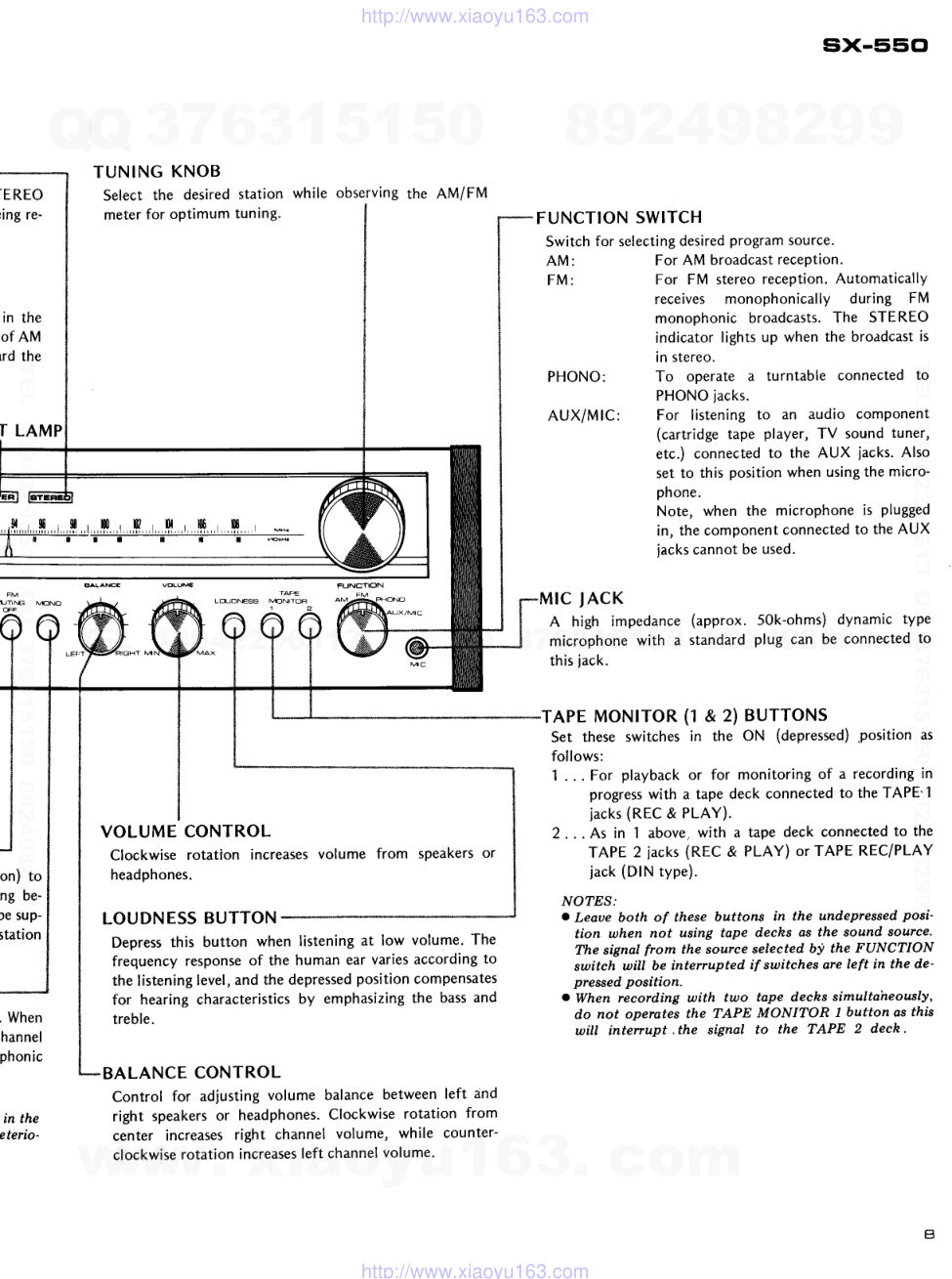
TUNING KNOB
Select the desired station while observing the AM/FM
meter for optimum tuning.
FUNCTION
VOLUME CONTROL
Clockwise rotation increases volume from speakers or
headphones.
LOUDNESS
BUTTON
Depress this button when listening at low volume. The
frequency response of the human ear varies according to
the listening level, and the depressed
position compensates
for hearing characteristics
by emphasizing the bass and
treble.
BALANCE CONTROL
Control for adjusting volume balance between left and
right speakers or headphones.
Clockwise rotation from
center increases right channel volume, while counter-
clockwise rotation increases
left channel volume.
FUNCTION SWITCH
Switch for selecting
desired program source.
A M :
F M :
PHONO:
AUX/MIC:
sx-s5cl
For AM broadcast reception.
For FM stereo reception. Automatically
receives monophonically during FM
monophonic broadcasts.
The STEREO
indicator lights up when the broadcast is
in stereo.
To operate a turntable connected to
PHONO iacks.
For listening to an audio component
(cartridge tape player, TV sound tuner,
etc.) connected to the AUX jacks. Also
set to this position when using the micro-
phone.
Note, when the microphone is plugged
in, the component connected to the AUX
iacks cannot be used.
(approx. 50k-ohms) dynamic tYPe
standard plug can be connected to
(1 &.2) BUTTONS
in the ON (depressed)
.position as
lNM
rcNO
LruOMS
rc JAcK
A high impedance
microphone with a
this lack.
TAPE MONITOR
Set these switches
follows:
1 . . . For playback or for monitoring of a recording in
progress
with a tape deck connected to the TAPE'1
iacks (REC & PLAY).
2 . . . As in 1 above, with a tape deck connected to the
TAPE 2 jacks (REC & PLAY) oTTAPE REC/PLAY
jack (DlN type).
NO?ES:
o Leaue both of these buttons in the undepressed'
posi-
tion when not using tape dechs as the sound source.
The signat from the source selected by the FUNCTION
switch will be interrupted if switches are left in the d'e'
pressed position.
a When record.ing with two tape dechs simultaheously,
do not operates the TAPE MONITOR I button as this
will interrupt .the signal to the TAPE 2 dech.
a
www. xiaoyu163. com
QQ 376315150
9
9
2
8
9
4
2
9
8
TEL 13942296513
9
9
2
8
9
4
2
9
8
0
5
1
5
1
3
6
7
3
Q
Q
TEL 13942296513 QQ 376315150 892498299
TEL 13942296513 QQ 376315150 892498299
http://www.xiaoyu163.com
4. CIRCUIT DESCRIPTIONS
F ig. 1 Tuner Section
TUNER SECTION
FM Front End
A frequency linear 3-gang variable capacitor is
used with a single stage FET RF amplifier. The
FET possesses high input impedance compared
with a transistor, and allows simple coupling with
the input tuning circuit, plus a significant advan-
tage in terms of noise.
The local oscillator is a variation of a Clapp circuit
and its
excellent temperature compensation
provides stable frequency even without AFC.
Local oscillator voltage is passed through a low
value capacitor to the mixer transistor base.
lF Amplifier and Detector
Composed of two dual element ceramic filters and
one IC (HA1137). The HAl1BT is a high density
IC and contains a limiter amplifier, FM detector
(quadrature detector), muting, and meter drive
*21
circuits.
Multiplex Demodulator
The IC (HA1156W) used in this section does not
-1s
require a tuning coil and in addition to a pLL
stabilized switching signal generator circuit, it
contains a double balanced differential amplifier
switching system demodulator circuit and an auto_
matic stereo-mono selector circuit. An extemal
switching transistor controlled by the FM muting
signal provides automatic monophonic reproduc-
!t_91 "t input sigrrals below the muting level (FM
MUTING switch OFF). The stereo demodulator
signal passes through the de-emphasis circuit, then
through an amplifier that combines carrier filter
and crosstalk canceller to produce the demodula_
tor output.
AM Tuner
Composed of a single IC (HA11BS) and dual
element ceramic filter. A 2-gar,:rg
variable capacitor
is employed with one stage providing tuning be_
tween the antenna and RF amplifier and the
other stage tuning the local oscillator. The RF
amplifier itself is not tuned but feeds direcfly to
the mixer followed by a 2-stage IF amplifier.
PHONO EOUALIZER AMPLI FIER
IC (TA7136P1) is used with independent left and
right channels. Tolerances !2Vo styrole capacitors
and tolerances !1Vo metal oxide resistors comprise
the equalizer elements, leading to an RIAA devia-
tion within 0.3dB from 30Hz to 15kHz.
Fig.2 PHONO Equalizer
MICROPHONE
CIRCUIT
A
single transistor amplifier (monophonic) is
provided in addition to the phono equalizer ampli_
fier. A selector switch cuts the AUX jack iniut
when a plug is inserted into the MIC jack. ihe
amplified microphone signal is then supplied to
both the left and right channels. The FUNCTION
switch is set to the AUX position when using a
microphone.
www. xiaoyu163. com
QQ376315150
9
9
2
8
9
4
2
9
8
TEL 13942296513
9
9
2
8
9
4
2
9
8
0
5
1
5
1
3
6
7
3
Q
Q
TEL 13942296513 QQ 376315150 892498299
TEL 13942296513 QQ 376315150 892498299
http://www.xiaoyu163.com
When the power switch is set to OFF, point C
potential instantly becomes - 16V. Q4 becomes
ON and C2 is immediately discharged. Since this
interval is extremely brief, the muting time remains
constant even if the power switch is again set to
oN.
Fig. 3 Microphone
Circuit
TONE CONTROL
A CR network tone control circuit is employed in
which each attenuator circuit consists of a capaci-
tor and a resistor. These function to increase and
decrease the relative levels of low and high fre-
quency sounds. Since relative control over the fre-
quency response by the attenuator results in a
constant loss, an amplifier (Q1 & Q2) is used prior
to this stage for compensation. The control ranges
are +8dB to -8dB for the highs (at 10kHz) and
+9dB to -gdB for the lows (at 100H2).
YR1:TREBLE
CONTfuL
VRz: BA55 CONJROL
Fig.4 Tone Control
AF MUTING AMPLIFIER
When the power switch is set to ON, the potential
of point C in Fig. 5 instantly rises due to C3 &
Rb time constant, and Q4 becomes OFF. Point B
potential at this time gradually increases with the
C2 & Rg time constant and normally reaches -19V.
Q3 becomes OFF when point B is below -15.4V,
from which time point A potential rises with the
CL & Rl time constant and normally reaches
approximately 8V from R1 & R2. FET Q1 & Q2
operate when point A potential is above 0V. The
muting interval (T) extends from the time the
power supply is set to ON to when point A poten-
tial reaches 0V. This interval is set f.or 6 -
7
seconds.
F ig. 5 AF Muting
Fis. 6
POWER AMPLI FIER CIRCUIT
Composed of differential
first stage, all stages
direct coupled pure.complementary OCL circuit.
Open gain at lkHz is approximately 80dB and
NFB amount is approximately 50d8. R3 and R4
are provided with this circuit in order to obtain
adequate stability even with the NFB disconnected.
Q1 form a differential amplifier: IIOVo d.c. feed-
back is applied from the junction point of the
power stage to the base of Ql so the potential of
the junction point is always maintained at the
same level.
Control amP.0UT
Power amp. I N
Conlrol amp. OUT
Powef amo. lN
P o r n t B
POWER
OFF
Fig.7 Power AmPlifier
www. xiaoyu163. com
QQ376315150
9
9
2
8
9
4
2
9
8
TEL 13942296513
9
9
2
8
9
4
2
9
8
0
5
1
5
1
3
6
7
3
Q
Q
TEL 13942296513 QQ 376315150 892498299
TEL 13942296513 QQ 376315150 892498299
http://www.xiaoyu163.com
sx-55cl
POWER SUPPLY
High stability (ripple cancelling efficiency) is
required in the power supply circuit due to its
minimized output impedance. In the circuit shown
in the Fig. 8, Q1 is controlled by Q2, which detects
its output variations. Tuner power is taken from
Q3 emitter. Since this is at the power transformer
secondar5r, AC line variations do not directly reach
the tuner.
Power Amp. *--
P o w e r A m o . +
Power Anp. +
It4lC Amp.
AF lrUT Amp
EQ Amp.
MUT Amp.
EQ Amp.
MUT Amo.
Fig. 8 Power Supply
www. xiaoyu163. com
QQ376315150
9
9
2
8
9
4
2
9
8
TEL 13942296513
9
9
2
8
9
4
2
9
8
0
5
1
5
1
3
6
7
3
Q
Q
TEL 13942296513 QQ 376315150 892498299
TEL 13942296513 QQ 376315150 892498299
http://www.xiaoyu163.com
5. BLOCK DIAGRAM
UE
x
f f +
a
o
q
l
II
:>
o ^
q
,
'
I1
:?9
- l Y
:i
5t
'L_
€
e
c
F
s
^
E
,
6
E
F
€
o
- ,
( v
o
(
o
,
5
,
5
9
-
Z
l
-
l
-
-
>
:
u
d
G.
ur
o
o
(J
l!o
X
o-
E
-
&
z
O
t
U
F
? t ,
o
- - t , 6
a
L
o
E
O +
a q
L Oc
+
o
< ;
d . :
c
o
o
i i o
_
E
!-l -f -
gi 4'-
=!Fl-J*-'l
< r blW-!19.1!f/l
l=::--.
o+
L.)
CD
>
<
+
-
LL
$ 5 ?
z
=
O ' D <
I
- L 6 ^ ;
O ; U
i '
z
q
;= €El?
qr
3^ 3 -lE 3l
I
y - - l :
I
L =li 3ll z
z { l u
o - l
. <
-
l a
r u n
L . _ l
c . ) . - j O N
r;l
iai I
! : i
r d t
l ! l
I
L - -
r
l
-
l - l
! F l
l * L
i
l : k
L.€-
r/)
(/)
(a
;
U
F
z.
I
i
i
i
i
i
L
rI
i
,
l
(L
E
c,ul
zo
F
I
t!
t/,
Joc.
l-zo
IJ
f-
Iir
c=
(-,
E
L
o
E
E
I
I
t
so
oo
L
o+
o . =
H 3
r l
J
t
* l
u J 'FI
ill
L.
t
|*
o
o
z
0
r t
u
z
z.U
F
z
-tl
el
G , ,
tr.l I
l lti
www. xiaoyu163. com
QQ376315150
9
9
2
8
9
4
2
9
8
TEL 13942296513
9
9
2
8
9
4
2
9
8
0
5
1
5
1
3
6
7
3
Q
Q
TEL 13942296513 QQ 376315150 892498299
TEL 13942296513 QQ 376315150 892498299
http://www.xiaoyu163.com
sx-55cl
6. LEVEL DIAGRAM
60
50
40
30
20
1 0
0
- 1 0
-20
- 3 0
- 4 0
LEVEL
( dBv)
- 5 0
- 6 0
13.sv
(80 )
rT---r
cr)
c!
c!
cr)
I
AUX ( 150mV)
A
MIC ( 7.5mV
)
c!
I
(r)
6
o
PH0N0
( 2.5mV)
0dBv: lV
FREOUENCY:
lkHz
t 5
www. xiaoyu163. com
QQ376315150
9
9
2
8
9
4
2
9
8
TEL 13942296513
9
9
2
8
9
4
2
9
8
0
5
1
5
1
3
6
7
3
Q
Q
TEL 13942296513 QQ 376315150 892498299
TEL 13942296513 QQ 376315150 892498299
http://www.xiaoyu163.com
7. D'SASSEMBLY
REMOVE SIDE BOARDS
Side board can be removed by taking out 4 screws
shown in figure. When reinstalling, observe that
space does not occur between them and front
panel.
NS
REMOVE TOP PLATE
Take out 2 screws shown in figure to remove.
www. xiaoyu163. com
QQ376315150
9
9
2
8
9
4
2
9
8
TEL 13942296513
9
9
2
8
9
4
2
9
8
0
5
1
5
1
3
6
7
3
Q
Q
TEL 13942296513 QQ 376315150 892498299
TEL 13942296513 QQ 376315150 892498299
http://www.xiaoyu163.com
six-E'5Ct
REMOVE BOTTOM PLATE
Take out 8 screws shown in
ward to remove.
figure and pull rear-
2
REMOVE FRONT PANEL
Use allen hex wrench to loosen tuning knob set-
screw and remove knob. Pull off all knobs (except
push buttons), then remove shaft nuts of FUNC-
TION and SPEAKERS switches. Take out upper
left and right screws (2 screws) of front panel
and remove.
- c )
-*+g;{:':i';:-*
8
II
)/4 ":(
,:,"LW
www. xiaoyu163. com
QQ376315150
9
9
2
8
9
4
2
9
8
TEL 13942296513
9
9
2
8
9
4
2
9
8
0
5
1
5
1
3
6
7
3
Q
Q
TEL 13942296513 QQ 376315150 892498299
TEL 13942296513 QQ 376315150 892498299
http://www.xiaoyu163.com
8. DIAL CORD STRINGING
1. Tie end of cord to inner stud of dial pulley.
2. Close tuning capacitor blades fully.
3. Pass cord through dial pulley opening, make a
half turn around pulley, then pa.ss in the route:
pulley A-dial needle-B-C-dial shaft-D-dial pulley.
4. Wind cord clockwise (as viewed Fom rear panel)
3 turns around dial shaft, then route to pulley D.
5. Wind 3 turns around dial pulley and tie to spring
so that the cord is under tension.
6. Turn TUNING
knob and confirm that dial
needle moves smoothly.
7. With tuning capacitor blades fully closed, move
dial needle to starting point (left edge of scale).
8. Apply lacquer to tied ends of cord.
CAUTION:
Do not touch dial needle with the hand.
Handle dial needle only by the molded portion. Smudges
and finger-prints cannot be removed from metallic portion
of needle.
Dial pulley
Dial shaft
needle
\
B
r O )
''z-'
www. xiaoyu163. com
QQ376315150
9
9
2
8
9
4
2
9
8
TEL 13942296513
9
9
2
8
9
4
2
9
8
0
5
1
5
1
3
6
7
3
Q
Q
TEL 13942296513 QQ 376315150 892498299
TEL 13942296513 QQ 376315150 892498299
http://www.xiaoyu163.com
9. ADJUSTING PROCEDURES
9.1 AM SECTION
1. Through a lk ohm resistor, connect an AM
signal generator to the AM antenna terminal.
Set for 400H2 at 30dB and 30% modulation.
2. Connect AC VM (Voltmeter) to TAPE REC
jack (L or R).
Set FUNCTION switch to AM position.
Set AM SG and SX-550 dial indication to point
A (60OkHz).
Adjust T6 for maximum indication on AC VM.
Set AM SG and SX-550 dial indication to Doint
C (1,400kH2).
I
,l
o .
sx-Ei='Cl
7. Adjust TC4 for maximum indication on AC
VM.
8. Again set AM SG and SX-550 dial indication to
point A.
9. Adjust bar antenna core for maximum indica-
tion on AC VM.
10. Return AM SG and SX-550 dial indication to
point C.
11. Adjust TC5 for maximum indication on AC
VM,
12. Repeat steps 4-11 to eliminate variations in
AC VM indications at points A and C.
r
:
AC voltmeter
1k ohm resistor t r @
www. xiaoyu163. com
QQ376315150
9
9
2
8
9
4
2
9
8
TEL 13942296513
9
9
2
8
9
4
2
9
8
0
5
1
5
1
3
6
7
3
Q
Q
TEL 13942296513 QQ 376315150 892498299
TEL 13942296513 QQ 376315150 892498299
http://www.xiaoyu163.com
9.2 FM SECTION
1. Through 300 ohm dummy antenna, connect
FM signal generator to the 300 ohm FM
antenna terminals and set for 400H2 at 100d8
and IOOVo modulation.
2. Connect AC VM and distortion meter to TAPE
REC jack (L or R).
3. Set FUNCTION switch to FM and MUTING
switch to OFF.
Set FM SG and SX-550 dial indication to point
A (90MHz).
Adjust T3 for maximum indication on AC VM.
Adjust T5 lower core for center of scale indica-
tion on Tuning meter.
Set FM SG for 9dB output and adjust T1 and
T2 for maximum indication on AC VM.
Set FM SG and SX-550 dia.l indication to point
C (106MHz).
9. Adjust TC3, then TC1 and TC2 for maximum
indication on AC VM.
10. Again set FM SG and SX-550 dial indication to
point A.
11. Adjust T3, then T1 and T2 for maxirnum indi-
cation on AC VM.
12. Repeat steps 8-11 to eliminate variations in
sensitivity at points A and C.
13. Adjust T4 for maximum sensitivity.
14. Detune to noise only and adjust Tb lower core
for center of scale indication on Tuning meter.
15. Set SX-550 dial indication to point B (98MHz)
and adjust FM SG for center of scale indication
on Tuning meter.
16. Set FM SG output to 60dB and adjust Tb
upper core for minimum distortion.
1?. Repeat steps 14-16 to eliminate variations in
minimum distortion position.
(t.
,7
8.
!*
AC voltmeter
Distortion meter
Flvl signal generator
u @
www. xiaoyu163. com
QQ376315150
9
9
2
8
9
4
2
9
8
TEL 13942296513
9
9
2
8
9
4
2
9
8
0
5
1
5
1
3
6
7
3
Q
Q
TEL 13942296513 QQ 376315150 892498299
TEL 13942296513 QQ 376315150 892498299
http://www.xiaoyu163.com
9.3 MPX SECTTON
1. Through 300 ohm dummy antenna, connect FM
signal generator to 300 ohm FM antenna
terminals.
2. Connect multiplex signal generator to externa.l
modulation terminals of FM SG.
3. Connect oscilloscope horizontal input to MPX
SG pilot output and vertical input via probe to
TP (No. 31) of circuit board
sx-55Cl
4. Set SX-550 dial indication to 98MHz and adjust
FM SQ for center of scale indication on Tuning
meter.
5. With FM SG unmodulated, adjust VR1 so that
lissajous pattern on oscilloscope becomes sta-
tionary.
6. With MPX SG modulation 1kHz, L+R 67.5kHz
deviation and Pilot 7.5kHz deviation. adiust T4
for minimum distortion.
Oscilloscope
MPX signal generator
AC voltmeter
Distortion meter
n
Eo
l
l
-
300 ohm
dummy antenna
www. xiaoyu163. com
QQ376315150
9
9
2
8
9
4
2
9
8
TEL 13942296513
9
9
2
8
9
4
2
9
8
0
5
1
5
1
3
6
7
3
Q
Q
TEL 13942296513 QQ 376315150 892498299
TEL 13942296513 QQ 376315150 892498299
http://www.xiaoyu163.com
9.4 POWER AMPLIFIER (IDLE CURRENT)
1. Set BASS and TREBLE controls to FLAT
positions.
2. Connect DC voltmeter to circuit board TP
terminals (L = 34 o, 33 g; fi, = 35 @,36 o) and
adjust VR3 (L) and VR4 (R) for 25mV.
3. Readjust after approximately 15 minutes (speci
fication range is 15mV to 40mV).
DC voltmeter
E
i o
www. xiaoyu163. com
QQ376315150
9
9
2
8
9
4
2
9
8
TEL 13942296513
9
9
2
8
9
4
2
9
8
0
5
1
5
1
3
6
7
3
Q
Q
TEL 13942296513 QQ 376315150 892498299
TEL 13942296513 QQ 376315150 892498299
http://www.xiaoyu163.com
10.
10.1
PARTS LOCATION
FRONT PANEL VIEW
Front panel assembly
ANB.417
Knob (SPEAKER)
- -
AAB.lOO
i
Knob {BASS,
TREBLE)
AAB.O99
Knob (FM MUTING,
MONO)
AAD.l 1O
www. xiaoyu163. com
QQ376315150
9
9
2
8
9
4
2
9
8
TEL 13942296513
9
9
2
8
9
4
2
9
8
0
5
1
5
1
3
6
7
3
Q
Q
TEL 13942296513 QQ 376315150 892498299
TEL 13942296513 QQ 376315150 892498299
http://www.xiaoyu163.com
Knob (TUNING)
AAA-036
Knob (VOLUME)
AAB.11O
Knob (FUNCTION)
AAB.lOO
Knob IBALANCE)
AAB.O99
www. xiaoyu163. com
QQ376315150
9
9
2
8
9
4
2
9
8
TEL 13942296513
9
9
2
8
9
4
2
9
8
0
5
1
5
1
3
6
7
3
Q
Q
TEL 13942296513 QQ 376315150 892498299
TEL 13942296513 QQ 376315150 892498299
http://www.xiaoyu163.com
'IO.2 REAR PANEL VIEW
t t t t t I t t I t, t I t l, I t t r, I l l llln, | | | I | | | | | | | | | | | |
il t I il l l l l t l, il n,tilllilllltf f f t il il l l il ilr il
Term ina | (ANTENNA)
A K E . O 2 8
Term inal 4P
A K B - 0 2 7
DIN connector
( R E C / P L A Y )
A K P 0 1 1
23
socket
www. xiaoyu163. com
QQ 376315150
9
9
2
8
9
4
2
9
8
TEL 13942296513
9
9
2
8
9
4
2
9
8
0
5
1
5
1
3
6
7
3
Q
Q
TEL 13942296513 QQ 376315150 892498299
TEL 13942296513 QQ 376315150 892498299
http://www.xiaoyu163.com
AC socket (AC OUTLETS)
AKP OO4
n l llil | l t l il il nt tnttnilnrtl\tr\\\\\\\\
| | ll | | | | | | | | |lI IIIlltttltntttn\t\\\\\\\\\
AC power cord
ADG.OO5
Fuse cover
AEC 249
T e r m i n a l
( S P E A K E R S )
A KE-029
Ferrite bar-antenna
AXB.O06
www. xiaoyu163. com
QQ376315150
9
9
2
8
9
4
2
9
8
TEL 13942296513
9
9
2
8
9
4
2
9
8
0
5
1
5
1
3
6
7
3
Q
Q
TEL 13942296513 QQ 376315150 892498299
TEL 13942296513 QQ 376315150 892498299
http://www.xiaoyu163.com
10.3 TOP VtEW
Acrylic board
AEC,240
II
FW
**frn- Jr-
Electrolytic
capacitor
ACH-055
Tuning shaft assembly
A X A . 1 1 7
RF assembly
AWE.O72
Dial pulley assembly
AXA,O66
www. xiaoyu163. com
QQ376315150
9
9
2
8
9
4
2
9
8
TEL 13942296513
9
9
2
8
9
4
2
9
8
0
5
1
5
1
3
6
7
3
Q
Q
TEL 13942296513 QQ 376315150 892498299
TEL 13942296513 QQ 376315150 892498299
http://www.xiaoyu163.com
s)<-550
Lamp assembly
(PL1,2,3)
AE L 060
;'o I
(3, J l .
Power transformer (Tl )
ATT.263
AF assembly
AWK 056
AF MUTING assemblY
AWM,1O1
www. xiaoyu163. com
QQ376315150
9
9
2
8
9
4
2
9
8
TEL 13942296513
9
9
2
8
9
4
2
9
8
0
5
1
5
1
3
6
7
3
Q
Q
TEL 13942296513 QQ 376315150 892498299
TEL 13942296513 QQ 376315150 892498299
http://www.xiaoyu163.com
1O.4 FRONT VIEW
IVleter
AAW 053
Variable
resistor
(BASS, TREBLE)
A C V . 1 3 8
Push switch (Fl\,1
lvlUTlNG, IVIODE)
ASG.O92
Variable r
ACV 126
Phone iack (PHON
ES)
AKN-OO9
selector switch (SPEAKER
)
ASA-042
www. xiaoyu163. com
QQ376315150
9
9
2
8
9
4
2
9
8
TEL 13942296513
9
9
2
8
9
4
2
9
8
0
5
1
5
1
3
6
7
3
Q
Q
TEL 13942296513 QQ 376315150 892498299
TEL 13942296513 QQ 376315150 892498299
http://www.xiaoyu163.com
Tuning shaft assembly
AXA-1 17
Phone jack {MlC)
A K N , 0 1 1
Selector switch
( F U N C T I O N )
ASD.O48
Push switch {LOUDNESS,
TAPE l\,lONlTOR
1,2)
ASG-093
Variable
resistor
(VOLUME)
A C V 1 6 1
Variable
resistor
(BALANCE)
ACV,126
www. xiaoyu163. com
QQ376315150
9
9
2
8
9
4
2
9
8
TEL 13942296513
9
9
2
8
9
4
2
9
8
0
5
1
5
1
3
6
7
3
Q
Q
TEL 13942296513 QQ 376315150 892498299
TEL 13942296513 QQ 376315150 892498299
http://www.xiaoyu163.com
11. EXPLODED VIEWS
11.1 EXTERIOR
Lamp assembly
(PL1. 2, 3)
AEL-O6O
Wire connector
AEC-308
RT 3x6
Dial scale board
AAG.I13
BM 3x8
I
Washer
B�22-017
Knob (TUNING)
AAA-036
RT 3x8
AB4-066
Acrylic board
AEC-240
RT 3x8
ABA.066
Screw
A B A - 1 1 3
@.
%,
d--
€..
d
Side board (L)
AMS-012
ptate {L}
.-.AAH-02
capacitor "'..-
ACG-001
_6
'\
eP'
| <^'.
\a
Dial pointer
AAF-046
Nylon sheet
AEC-191
Knob (FM MUTING, MONO. LOUDNESS,
TAPE MONITOR)
A A D - 1 1 0
d
t
Wi'Nt
sprins
-<[,-
ABH-025
-'''t
SPacer
.,..-'
AEC-301
Front panel assembly
ANB.417
Washer
822-017
Nut
871-005
Knob (SPEAKER,
VOLUME. FUNCTION)
AAB-1OO
RT 3x6
e'
www. xiaoyu163. com
QQ376315150
9
9
2
8
9
4
2
9
8
TEL 13942296513
9
9
2
8
9
4
2
9
8
0
5
1
5
1
3
6
7
3
Q
Q
TEL 13942296513 QQ 376315150 892498299
TEL 13942296513 QQ 376315150 892498299
http://www.xiaoyu163.com
RT3x6
sx-5E'o
NOTE:
Parts indicated in green type cannot be supplied.
RT3x8
Plate
ANE-120
(KU, KC)
Screw
ABA.113
Side board (R)
AM$013
roard {L)
"''.
.012
Plate
{L)
.AAH.027
tor "\
)01
\E)
Terminal 2p
IMODEL KU}
ffi
PART 1
See page 3l
Plate (Rl
AAH-028
Union nut
ABN-025
%
%
?&-
j c
" c
' ---.':'i,--'--.-J-f
- n "
@
I
Screw
ABA.OO2
Foot assemblY
AEC.O83
eP'
RT 4x10
RT 4x10
www. xiaoyu163. com
QQ376315150
9
9
2
8
9
4
2
9
8
TEL 13942296513
9
9
2
8
9
4
2
9
8
0
5
1
5
1
3
6
7
3
Q
Q
TEL 13942296513 QQ 376315150 892498299
TEL 13942296513 QQ 376315150 892498299
http://www.xiaoyu163.com
11.2 PART 1
RT 4x8
RT 3x6
Plate (L)
AAH-O27
q-
\ \
\-fi''
_-'1
. .-- ---t-'t"'--...
Pulley shaft
M49-025
Power transformer
4TT-263 (KU)
ATT-305 (KC)
Rr 3x6 t
NOTE:
If set is a K
screwdriuer.
in dcmage.
oppoeite scr
thii screw.
RT3x6
AC soc
AKP.O
Angle
.N
Electrolytic capacitor (C6, 7) ANF-435
ACH-055-'E
1 e
,?q
%
t
t?
l__,
f,Tw
YIt 7
P
?<
-r*ta-\
RT 3x8
RT 3x6
PART 2 See pase 33
AF assembly
AWK-054 (KU)
AWK_056
(KC)
RT 3x8
Clip
AEC-036
PART 3
See pages 34
RF assembly
AWE.O72
q
.-\
Screw
ABA-122
RT 3x6
3 1
www. xiaoyu163. com
QQ376315150
9
9
2
8
9
4
2
9
8
TEL 13942296513
9
9
2
8
9
4
2
9
8
0
5
1
5
1
3
6
7
3
Q
Q
TEL 13942296513 QQ 376315150 892498299
TEL 13942296513 QQ 376315150 892498299
http://www.xiaoyu163.com
NOTE:
If set is a KC model, this screw cannot be remoued with a
screwdriuer. Forcibly
attempting
to remoue it will result
in damage. To remoue the fuse couer, first tahe.out the
oppoqite screw, then turn the entire fuse couer to unfasten
this screw.
RT 4x8
Fuse cover
AEC-249
T3x6
-.-
NOTE:
Parts indicated in green type cannot be supplied.
AC power cord
ADG.OOS
ffi
\
RT3x8p
/
W-
AC socket (AC OUTLETS)
AKP.OO4
Angle
) ANF-435
Sheet
AEC-250
a'*.,
/ / /
RT 3x8
T
,-
'r*;J.,*,"*\
AXB.006
___d
_d
^ &
Screw (GND)
?
AKE_031
.' _4
d
'
RT 3xg
RT 3x6
W
Yfl
42,
l/{
RT 3x6
RT 3x6
Pulley shaft
M49-025
Pulley
AEC-101
Switch
AEC-015
Plate (R )
AAH-028
Tuning shaft assembly
A X A - I 1 7
%
)
_d
Washer
822-016 ^, O-
N) fil
Nut
l\-
871-oo4 lw
d e - q
Wire holder
AEC-299
RT 3x6
Spacer
AEB-079
{
r3x6
]s
www. xiaoyu163. com
QQ376315150
9
9
2
8
9
4
2
9
8
TEL 13942296513
9
9
2
8
9
4
2
9
8
0
5
1
5
1
3
6
7
3
Q
Q
TEL 13942296513 QQ 376315150 892498299
TEL 13942296513 QQ 376315150 892498299
http://www.xiaoyu163.com
sx-55cl
11.3 PART 2 AF ASSEMBLY AWK-056
Phone jack (PHON E$l
AKN.OO9
i\
$ *
N T
$ r s I
w
l
RM 3x6
A.
^ -\D
I
/s
Nut
871-004
Push switch (FM
ASG-092
NOTE:
Parts indicated in green type cannot be supplied.
Capacitor cover AEC-279 (Model KU)
Selector switch (SPEAKE R )
ASA-042
' Variable resistor
ACV-138
Insulator
MUTING, MONO)
AEC-239
PM3x8
Spacer
AEC-248
E'e
I
ffi Io
Ed
I
ffi Ie
Fuse (0.8A)
A E K - I 1 1
Fuse
clip
AKR-013
(KC)
AKR.O3O
(KU}
RT3x6
Washer
8�22-016
AF muting
assembly
AWM.101
Fuse (1.5A)
AEK.104
Fuse clip
AKR.OI3
(K
AKR-O3O
(K
RT3x6
RT3xO
Fuse (4A)
AEK.lOO
e'tu
A U l
w
Terminal (SPEAKERS)
AKE-029
Slide switch (DE-EMPHASIS)
ASH-015
Heat sink
A N H . 1 1 7
l
\
I
r
l
t
l d )
a s
fr
RT3x6
RT3x6
.J5
www. xiaoyu163. com
QQ376315150
9
9
2
8
9
4
2
9
8
TEL 13942296513
9
9
2
8
9
4
2
9
8
0
5
1
5
1
3
6
7
3
Q
Q
TEL 13942296513 QQ 376315150 892498299
TEL 13942296513 QQ 376315150 892498299
http://www.xiaoyu163.com
11.4 PART 3 RF ASSEMBLY AWE-O72
871-004
Washer
822-016
NOTE:
Parts indicated in green type cannot be supplied.
Variable resistor
Variable resistor
ACV-161
Push switch
ASG-093
Selector
switch (FUNCTION)
ASD-048
Phone jack (M lC)
A K N - 0 1 1
5P connector socket ( REC/PLAY)
AKP-o11
Terminal 4P
AKB.O27
Terminal
(ANTENNA)
AKE-028
Variable
capacitor
ACK-012
rut
u
Dial pulley assembly
AXA-066
RT3x6
PM 3x6
Ffu\
l? J' -"^?
34
www. xiaoyu163. com
QQ376315150
9
9
2
8
9
4
2
9
8
TEL 13942296513
9
9
2
8
9
4
2
9
8
0
5
1
5
1
3
6
7
3
Q
Q
TEL 13942296513 QQ 376315150 892498299
TEL 13942296513 QQ 376315150 892498299
http://www.xiaoyu163.com
six-s5c,
NOMENCLATURE
OF SCREWS,
WASHERS
AND
The following symbols stand for screws, washers and
NUTS
nuts as shorvn in exploded view.
Symbol
Dascription
Shape
RT
Brazier head tapping screw
PT
Pan head tapping screw
nrrl
BT
Binding head tapping screw
s:
CT
Countersunk head taPPing screw
TT
Truss head tapping screw
F
ocT
Oval countersunk head tapping
screw
D:
PM
Pan head machine screw
0E
CM
Countersunk head machine
screw
)-
ocM
Oval countersunk head
machine screw
F=
TM
Truss head machine screw
F
BM
Binding head machine screw
F
PSA
Pan head screw with spring
lock washer
GE
PSB
Pan head screw with spring
lock washer and f lat washer
GH
PSF
Pan head screw with f lat washer
d:
Symbol
D$cription
Shape
EW
E type washer
@
\D
II
FW
Flat washer
@ i l
sw
Spring lock washer
@
$
N
Nul
O E
WN
Washer faced nut
@ f l
tTw
Internal toothed lock washer
@ i l
OTW
Outernal toothed lock washer
# l
sc
Slotted set screw (Cone pointl
C E D
SF
Slotted set screw (Flat point)
c E l
HS
Hexagon socket headless sel
screw
@
D
ocw
Oval counterzunk head wood
screw
cw
Countersunk head wood screw
RW
Round head wood screw
EXAMPLE
T T
|
-lensth
in mm ( / )
I
diameter in mm (d )
FW 9dx1t
l-T
L-tni"knessinmm(r) +'
I
I
diameter
in mm (d )
q
Symbol
trF
ffi'
Symbol
35
www. xiaoyu163. com
QQ376315150
9
9
2
8
9
4
2
9
8
TEL 13942296513
9
9
2
8
9
4
2
9
8
0
5
1
5
1
3
6
7
3
Q
Q
TEL 13942296513 QQ 376315150 892498299
TEL 13942296513 QQ 376315150 892498299
http://www.xiaoyu163.com
12. SCHEMAf,IC DIAGRAMS. P.C. BOARD PATTERNS
AND PARTS LISTS.
12.1 MISCELLANEOUS
PARTS LIST
NO?ES:
:";:#:::::":":.:^i;'::i::':;f"::::::l,o{,un,*,*
TRANSFORMFRS AND COILS
CAPACITORS
TRANSFORMERS
AND COILS
Symbol
Description
Part No.
T1
T2
Power transformer
Bar-antenna assembly
ATT.263 (KU)
ATT-305 (KC)
AX8.006
External Appearance
of Transistors and lCs
2SA81 6
2S8596
2SD313 c
2SD526
Symbol
Description
Part No.
c1
c2
c3
c4
c5
c6
c7
c8
Ceramic
Ceramic
Ceramic
Ceramic
Ceramic
Electrolytic
6,800
35V
Electrolytic
6,800
35V
Ceramic
0.O1
50V
0.01
250v
0.01
125V
0.01
50v
0.01
50v
0.01
50v
ACG-001
ACG-003
CKDYF t03z 50
CKDYF 1032 50
CKDYF 1032 50
ACH-055
ACH-055
CKDYF 1032 50
RESISTOR
Symbol
Description
Part No.
R 1
Carbon film
2.2M
%w
RDY.PS225J
9roilt2trl41516
Ec
B
llii33w,".",
TA7 1 36P1
25A697
2sA725 ITFEg
2S,C1211 w>-B
25C1312
89loll12l3l4
,"bHolsb['\
HAl 156w-P
0USw
Indox
2sA7s8
ffi"
i333i:^61';
2SC1
438
LAMPS AND FUSES
Symbol
Description
Part No.
FU1
FU2
FU3
FU4
FU5
FU6
PL1
PL2
PL3
PL4
PL5
Lamp assembly (8V, 3O0mA)
Lamp assembly (8V, 30OmA)
Lamp assembly (8V, 30OmA)
Power indicator (6V, 50mA)
Stereo indicator {6V, 50mA)
Fuse (4A)
Fuse (4A)
Fuse (0.8A)
Fuse (0.8A)
Fuse (1 .5A)
Fuse (4A)
AEL.O6O
AEL-O6O
AEL-O6O
AEL.O62
AEL-061
AEK.lOO
AEK-1OO
AEK-1
11
A E K - l 1 1
AEK.104
AEK.l OO
36
2sc461
ftz
2SC535 €--l - e
2sK55
ryGA
www. xiaoyu163. com
QQ376315150
9
9
2
8
9
4
2
9
8
TEL 13942296513
9
9
2
8
9
4
2
9
8
0
5
1
5
1
3
6
7
3
Q
Q
TEL 13942296513 QQ 376315150 892498299
TEL 13942296513 QQ 376315150 892498299
http://www.xiaoyu163.com
12.2 SCHEMATIC
DIAGRAM
SWITCHES
i
...
SI
SPEAKERS
1.
POWER OFF
2 f f i
3
SP OFF
+ . S P B
5 . S P A + B
Sz
FM nUTttlO
N t o r r
Sg
MODE
srEs,fo -
MoN0
S+
TAPE , oNrrOR I
OFF -
ON
TAPE MONITOR 2
OFF
ON
LOUONESS
O F F - O N .
DE EI1PHASIS
'l5rS -
25/S
FUNCTION
l.
All
2 .
F M
3
PHONO
4
Aux/ fl tc
RESISfORS;
lN oHM, y
0.T1{ERWI
CAPAffTORS;
&F
UNL
| - v l
: s t G ' l A
V ,.:, 96 Yg1
05
^
F
Ll*(J
S5
RF AsS'/ AWE -0?2
o,-zsciEil--l
BAL
tso
GND
i o,2St 1. 本站所有素材,仅限学习交流,仅展示部分内容,如需查看完整内容,请下载原文件。版权声明
2. 会员在本站下载的所有素材,只拥有使用权,著作权归原作者所有。
3. 所有素材,未经合法授权,请勿用于商业用途,会员不得以任何形式发布、传播、复制、转售该素材,否则一律封号处理。
4. 如果素材损害你的权益请联系客服QQ:77594475 处理。