先锋PIONEER SX-4音响电路图
 "先锋PIONEER SX-4音响电路图-0")
 "先锋PIONEER SX-4音响电路图-1")
 "先锋PIONEER SX-4音响电路图-2")
 "先锋PIONEER SX-4音响电路图-3")
 "先锋PIONEER SX-4音响电路图-4")
 "先锋PIONEER SX-4音响电路图-5")
 "先锋PIONEER SX-4音响电路图-6")
 "先锋PIONEER SX-4音响电路图-7")
 "先锋PIONEER SX-4音响电路图-8")
 "先锋PIONEER SX-4音响电路图-9")
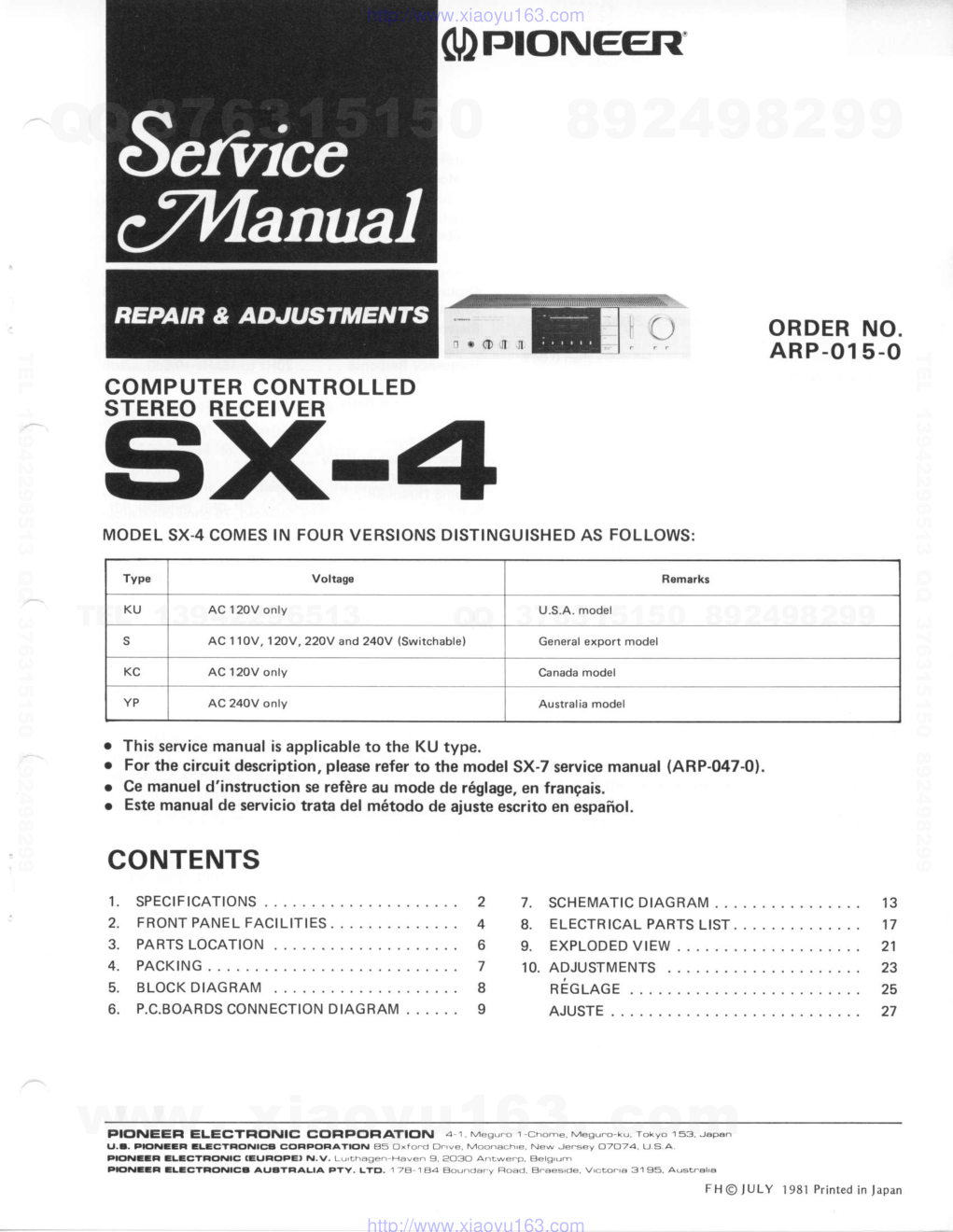
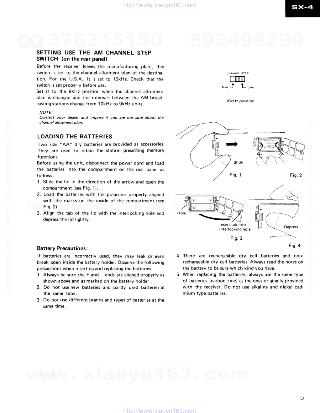
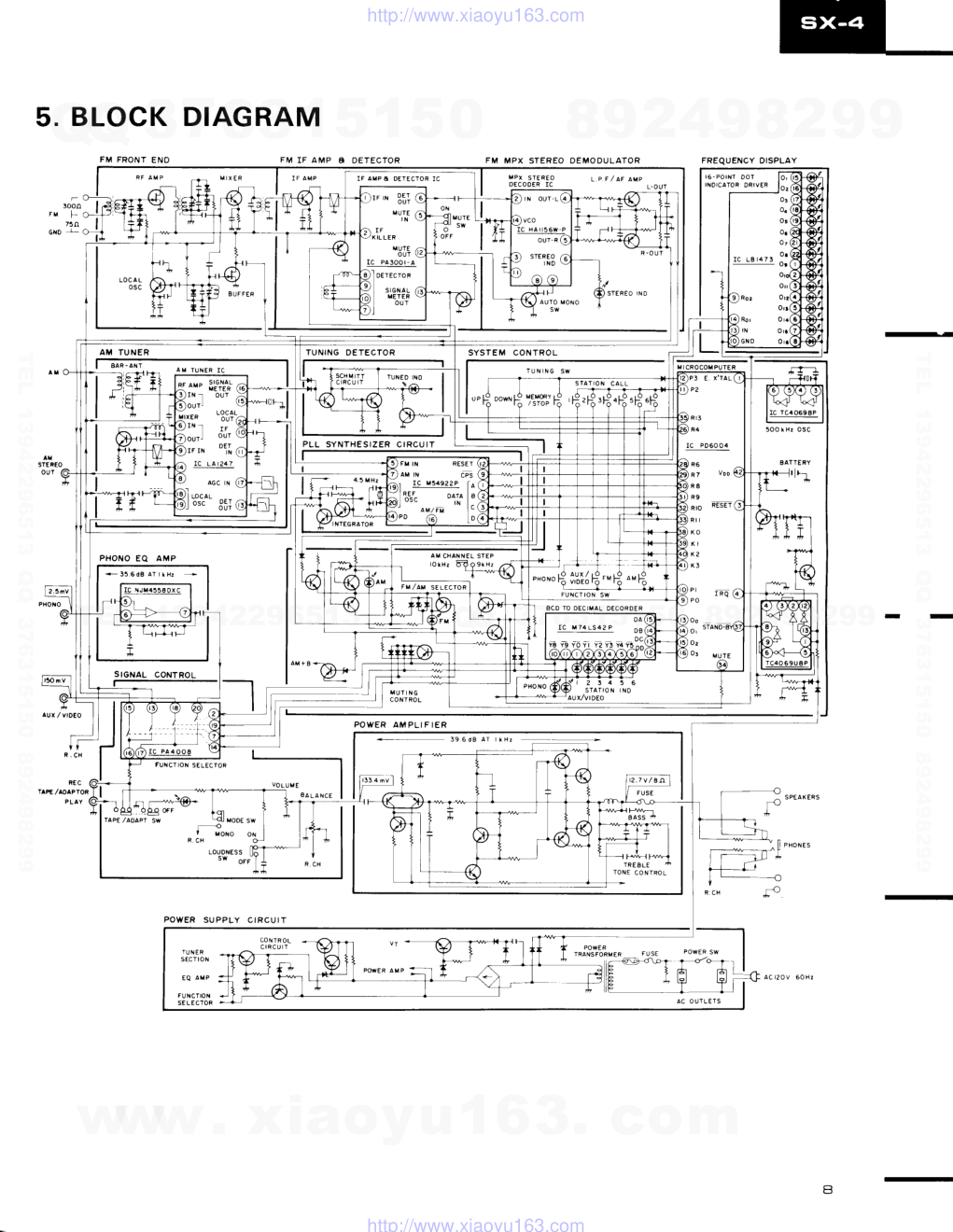
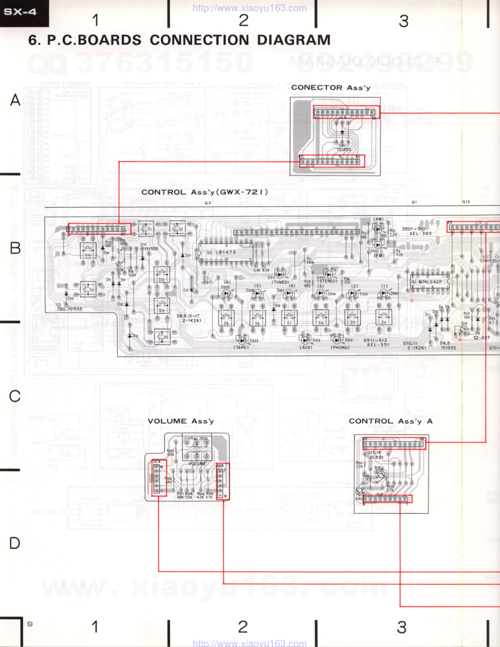
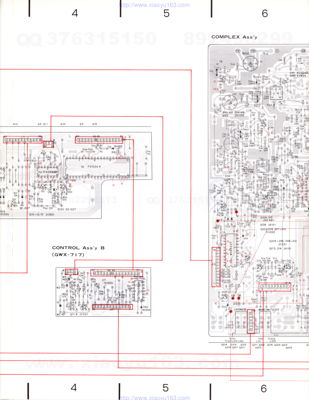
c)ProNEEr{ 2 4 6 I I 8. 9. 10. ORDER NO. ARP-O15-O COMPUTER CONTROLLED STEREO RECEIVER s)(- MODEL SX.4 COMES IN FOUR VERSIONS DISTINGUISHED AS FOLLOWS: r This service manual is applicable to the KU type. o For the circuit description, please refer to the model SX-7 service manual {ARP-047-0). r Ce manuel d'instuction se refdre au mode de r6glage, en frangais. o Este manual de servicio trata del m6todo de ajuste escrito en espafrol. 1 . 2. 3. o . 1 3 1 7 21 23 za 27 CONTENTS SPECIFICATIONS F RONT PANE L FACILITIES PARTS LOCATION 4. PACKING BLOCK DIAGRAI\4 P.C.BOARDS CONNECTION DIAGRAM PIoNEEFIELECTFICINICCG,F|PCTF|AI|CTN r-chome.M6su.o-ku.r (,.a. FE N--ll aLaCtFCtNlce CC,FIPC'AATIC'N 85 Oxro.ct O.'ve. Moona.h'e, New Je.sey O2O74. u s a PE illla tl.-CtFCtNlC IEUFC'PE, N.V. Lu'.haAe.-Haven 9.2O3o FlCrialCF lLaCTElC'NlCa AUaIFIALIA F Y. LYo. 1 7E' I A4 Aolnda.y Rodd, B.aes'de FHOTULY 1981 Printed in japan SCHEMATIC DIAGRAM ELECTR ICAL PABTS LIST . EXPLODED VIEW ADJUSTMENTS nEcuce AJUSTE Type Voltag€ Remarks KU AC 12OV only U.S.A. model s AC 110V, 120V,220V and 24OV (Switchable) General export model KC AC 12OV only Canada model YP AC 240V only Australia model www. xiaoyu163. com QQ 376315150 9 9 2 8 9 4 2 9 8 TEL 13942296513 9 9 2 8 9 4 2 9 8 0 5 1 5 1 3 6 7 3 Q Q TEL 13942296513 QQ 376315150 892498299 TEL 13942296513 QQ 376315150 892498299 http://www.xiaoyu163.com 1. SPECIFICATIONS Amplifier Section Continuous Average Power 0utput is 20 watts* per channel, min., at 8 ohms from 20 Hertz to 20,000 Hertz with no more than 0.04% total harmonic distortion. Total Harmonic Distortion (20 Hertz to 20,000 Hertz, 8 ohms, from AUX/VIDEO) continuous rated power output . . No more than 0.04% 10 watts per channel power output . . No more than 0.04% f ntermodulation Distortion (50 Hertz: 7,000 Hertz = 4 : 1, 8 ohms, from AUX/VIDEO) continuous rated power output . . No more than 0.04% Damping Factor l2O Hertz to 20,000 Hertz, 8 ohms) 50 I n put (Sensitivity/l mpedance) P H O N O . . . . 2 . 5 m Y l b 0 k i t o h m s AUX/VIDEO TAPE PLAY 150mV/50 kitohms Phono Overload Level (T.H.D. O.1"/o, 1,000H2) PHONO 130mV Output ( Level/l mpedance) TAPE REC .15OmVl2.2 kitohms Frequency Response PHONO (R IAA Equalization) . . . . 30Hzto 15.000H2t0.5d8 AUX/VIDEO. TAPE PLAY ronr'coniro; " " 10H2 to 50'000H21! uoe B A S S . . . . t 8 d B ( 1 0 0 H 2 ) T R E B L E . . 1 8 d 8 ( t O k H z ) '"':::'::::::':lY: ::' *::':l:': :: i?::Jil$Tl, Hum and Noise (lHF, short circuited A network) PHONO 70dB A U X / V I D E O , T A P E P L A Y . . . . . 9 6 d 8 FM Tuner Section Usable Sensitivity . Mono; 11..2d8f (lHF) (1.OpV,75 ohms) 50dB Ouieting Sensitivity Mono; 16.3dBf (1 .8pV, 75 ohms) Stereo; 37.2dBI (19.9pV, 75 ohms) Signal-to-Noise Ratio Mono; 75dB (at 85dBf ) Stereo;70d8 (at 85dBf) Distortion (at 65dBf) M o n o . . . . 1 0 0 H 2 ; 0 . 1 5 % 1 kHz; 0.1 5% 6kHz;O.2% S t e r e o . . . . 1 0 0 H 2 ; 0 . 3 % l kHz; 0.3% 6kHz; O.4o/o C a p t u r e R a t i o . . . . . 1 . 0 d 8 Alternate Channel Selectivity 400kHz; 60dB S t e r e o S e p a r a t i o n . . . . 1 k H 2 ; 4 0 d 8 30Hz to 'l5kHz; 35dB Frequency Response 20Hz to 15kHz +0.5d8, -1dB S p u r i o u s R e s p o n s e R a t i o . . . . 6 5 d 8 l m a g e R e s p o n s e R a t i o . . . . . . 6 5 d 8 l F R e s p o n s e R a t i o , . . 9 0 d 8 AM Suppression Ratio . 55dB S u b c a r r i e r P r o d u c t R a t i o . . . . 4 0 d 8 SCA Rejection ratio . . 60dB Muting Threshold 29.3dBf (8pV) Antenna Input . . 300 ohms balanced, 75 ohms unbalanced AM Tuner Section Sensitivity lHF, ferrite antenna . . 300pV/m lHF, external antenna 15gV Selectivity .27d8 Signal-to-Noise Ratio . 50dB l m a g e R e s p o n s e R a t i o . . . . . . 4 0 d 8 l F R e s p o n s e R a t i o . . . . . . . 7 3 d 8 Antenna Built-in ferrite loopstick antenna Miscellaneous Power Requirements AC 120V.60Hz Power Consumption . . .200W (UL) Dimensions . 420(W) x 98(H) x 311(D) mm 16-9/16(W) x 3-718(H) x 12-114(Dl in Weight (without package) 5.2 kg (1 1 lb 7 ozl Furnished Parts FM T-type Antenna 1 D r y B a t t e r y s u M - 3 " A A " . . . . . 2 O p e r a t i n g l n s t r u c t i o n s , . . . . . . 1 *Measured pursuant to the federal Trade Commission's Trade Regulation rule on Power Output Claims for Amplif ier. NOTE: Specifications and design subiect to possibte modification without notice. www. xiaoyu163. com QQ 376315150 9 9 2 8 9 4 2 9 8 TEL 13942296513 9 9 2 8 9 4 2 9 8 0 5 1 5 1 3 6 7 3 Q Q TEL 13942296513 QQ 376315150 892498299 TEL 13942296513 QQ 376315150 892498299 http://www.xiaoyu163.com SETTING USE THE AM CHANNEL STEP SWITCH (on the rear panel) Before the receiver leaves the manufacturing plant, this switch is set to the channel allotment olan of the destina- tion. For the U.S.A., it is set to 1OkHz. Check that the switch is set properly before use. Set it to the 9kHz position when the channel allotment plan is changed and the intervals between the AM broad- casting stations change from 1OkHz to 9kHz units. NOTE: Contact your dealer and inquire if you are not sure about the c han nel al I otment pla n. LOADING THE BATTERIES Two size "AA" dry batteries are provided as accessories. They are used to retain the station presetting memory functions. Before using the unit, disconnect the power cord and load the batteries into the compartment on the rear panel as follows: 1. Slide the lid in the direction of the arrow and open the co mp a rt m ent (see Fig. 1). Load the batteries with the polarities properly aligned with the marks on the inside of the compartment (see F i s . 2 ) . Align the tab of the lid with the interlocking hole and depress the lid lightly. Battery Precautions: lf batteries are incorrectly used. they may leak or even break open inside the battery holder. Observe the following precautions when inserting and replacing the batteries. 1. Always be sure the + and - ends are aligned properly as shown above and as marked on the battery holder. 2. Do not use new batteries and partly used batteries at the same time. 3. Do not use different brands and types of batteries at the same time. niT-trn ".r.J L'orr. 10kHz position Fig.2 Insert tab into interlocking hole Fis. 3 F i s . 4 There are rechargeable dry cell batteries and non- rechargeable dry cell batteries. Always read the notes on the battery to be sure which kind you have. When replacing the batteries, always use the same type of batteries (carbon zinc) as the ones originally provided with the receiver. Do not use alkaline and nickel cad- mium type batteires. 2. 3. 4. 5. www. xiaoyu163. com QQ 376315150 9 9 2 8 9 4 2 9 8 TEL 13942296513 9 9 2 8 9 4 2 9 8 0 5 1 5 1 3 6 7 3 Q Q TEL 13942296513 QQ 376315150 892498299 TEL 13942296513 QQ 376315150 892498299 http://www.xiaoyu163.com 2. FRONT PANEL FACILITIES o powen swlrcH Power is supplied to the unit when this switch is depressed ("in" position). @ FM STEREo INDIcAToR This lights when receiving an FM stereo program. @ TU INDICATOR This lights when receiving the FM broadcasts. (This lights when depressed the FM switch). @ nru rNDrcAToR This lights when receiving the AM broadcasts. @ FREOUENcY scALE This scale is composed of 16light-emitting diodes (LEDs). During frequency scanning, the lighting moves from left to right or vice versa, depending on the direction corres- ponding to the TUNING SWITCH which has been de- pressed. @ rurueo rNDrcAToR This lights when the optimum tuning point has been located during reception. lt blinks when stations are being searched. @ TUNING switch This is used to tune in broadcasting stations. When de- pressed, the LEDs on the frequency scale light up in the leftward or rightward direction, depending on the direc- tion corresponding to the part of the TUNING switch which has been depressed. and frequency scanning starts. The TUNED indicator now starts to blink. When a station is located. the LEDs stop moving and the TUNED indicator lights up. The sound from the station can be heard in about 5 sec- onds. After that sound has been heard for these few sec- onds, the frequency scanning operation starts again. In this way, all the broadcasting stations are picked up in succession. NOTE: The sound of each station is heard for about 5 seconds but de- press the TUNING switch if this is not the required station or if you want to search the next station promptly. @ FM swrrcH Depress this switch for FM reception. @ nm swtrcH Depress this switch for AM reception. www. xiaoyu163. com QQ 376315150 9 9 2 8 9 4 2 9 8 TEL 13942296513 9 9 2 8 9 4 2 9 8 0 5 1 5 1 3 6 7 3 Q Q TEL 13942296513 QQ 376315150 892498299 TEL 13942296513 QQ 376315150 892498299 http://www.xiaoyu163.com 3. PARTS LOCATION Front Panel View Display cover ANR454 Top cover ANE.362 Front panel assembly - ANM075 Knob (POWER ) ------------5 AAD.406 Knob (BASS,TREBLE,BALANCE) AAB.274 Front View with Panel Removed AEL.379 NO?'Sr o The ! marh found on some component patts indicates the importance of the 6ofet! factor of the part. Therefore, when rcplscing, be sure to u8e ports of identical designation, o For your Parts Stoch Contrcl, the faet mouing items ore indicdted uith the marhs ** qnd * ** GENERALLY MOVES FASTER THAN , Thia clossification eholl be odiusted b! each dietibutor because it depend, on model number, te mp eroture, humidity, e tc. Knob {TUNING) AAD.4OO Knob (FMl AAD4O2 Knob (AMl AAD403 Knob (VOLUME) AAB.273 K n o b ( I N P U T ) AAD.399 A r * Push switch (POWER ASG-521 Knob (TAPE/ADPT. MONO, LOUDNESSI AAD-405 Knob (MEMORY/STOP) AAD4O4 Variable resistor (VOLUMEI ACT-128 I * 3{anged push switch (TAPE/ADPT. MONO, LOUDNESS} ASG'301 *t Tact switch ASG-177 Control assembly GWX-721 Phones jack {PHONES} AKN-029 Variable resistor ( ACT-140 Variable resistor (TREBLE) ACT-140 Variable resistor ACT-o23 www. xiaoyu163. com QQ 376315150 9 9 2 8 9 4 2 9 8 TEL 13942296513 9 9 2 8 9 4 2 9 8 0 5 1 5 1 3 6 7 3 Q Q TEL 13942296513 QQ 376315150 892498299 TEL 13942296513 QQ 376315150 892498299 http://www.xiaoyu163.com 4. PACKING No. Part No. De.cription 1. AHA-294 2. ARB439 3. ADHOo4 4. AHD-961 Side pad Operating instructions T-type FM €ntenna Packing case s*613 Rear Panel View * t Slide switch (AM CHANNEL STEPI ASH-O15 rerminal (AM STEREO OUTI AKB{76 Terminel (PHONO, AUX/VtDEO,R ECI AKB-079 Terminal (PLAYI AKB{77 Top View ,\ AC socker (AC OUTLETSI AKP-039 Strain reliet AEC-358 AC power cord ADG.O52 Terminal {SPEAKERS) AKE.lOI ti\ ** Fuse (5A) AEK-1OA Power transform€r ATT€39 .'! *r Fuse (3Al AEKI Ol www. xiaoyu163. com QQ 376315150 9 9 2 8 9 4 2 9 8 TEL 13942296513 9 9 2 8 9 4 2 9 8 0 5 1 5 1 3 6 7 3 Q Q TEL 13942296513 QQ 376315150 892498299 TEL 13942296513 QQ 376315150 892498299 http://www.xiaoyu163.com 5. BLOCK DIAGRAM FM FRONT END FM IF AMP A DETECTOR F M M P X S T E R E O D E M O D U L A T O R M P x S T E R E o L . P , F / A F A } A P D E C O D E R I C L - o u T 300n F M F G N O ! I F A U P A O E T E C T O R I C 'I oerecro a S I G N A L IIETER I o " TUNING OETECTOR 3 E. X'TAL I C P 0 6 0 0 4 R 7 V o o R 8 R 9 Rto RESET R t l K O K I X 2 K 3 . ' I R Q P O O o or vurE l,-o.0. I osc 351 bl P L L S Y N T H E S I Z E R C I R C U I T r I C M 5 4 9 2 2 P t ^ I llt oarr I a I - - " r N l " ^ M / F M I ' P O G ) L D + 3 5 . 6 d 8 A T l k H r 8 C D T O O E C I M A L O E C O R O E R FM,/Ail sELEcroR va vs vo Yt Y2 Y3 vi r U N E R SECTION E Q A M P FU NCTION S€ LE CTOR I POWER SW I - 1 # o r r I f Fr tql' lj jf FREQUENCY DISPLAY P O W E R A M P L I F I E R I O N E C O N T R O L P O W E R S U P P L Y C I R C U I T AUX ,/ Vt0€O M U T I N G C O N T R O L -- - F U N C T I O N S E L E C T O R r*}@* g€ oFF fcl sw q MoD€ sw ^ S P E A K E R S r f- -o v MoNo oN R , C H - r I p x o r t s -+& _=r"f l l - j - v n # I ', --{1 v - LOU0f{ES S sw oFF j R . C H A C 1 2 O V 6 0 H r a www. xiaoyu163. com QQ 376315150 9 9 2 8 9 4 2 9 8 TEL 13942296513 9 9 2 8 9 4 2 9 8 0 5 1 5 1 3 6 7 3 Q Q TEL 13942296513 QQ 376315150 892498299 TEL 13942296513 QQ 376315150 892498299 http://www.xiaoyu163.com 6.P 1 .C.BOARDS l2 CONNECTION DIAGRAM 3 A B CONTROL Ass'y(GwX-72 | ) Q 2 VOLUME AssV C CONTROL Ass'y A D www. xiaoyu163. com QQ 376315150 9 9 2 8 9 4 2 9 8 TEL 13942296513 9 9 2 8 9 4 2 9 8 0 5 1 5 1 3 6 7 3 Q Q TEL 13942296513 QQ 376315150 892498299 TEL 13942296513 QQ 376315150 892498299 http://www.xiaoyu163.com 6 5 4 COMPLEX Ass'y CONTROL Ass'y (awx-7,7) TC202 Qro5 o2o4 Q2r3 Q2O5 www. xiaoyu163. com QQ 376315150 9 9 2 8 9 4 2 9 8 TEL 13942296513 9 9 2 8 9 4 2 9 8 0 5 1 5 1 3 6 7 3 Q Q TEL 13942296513 QQ 376315150 892498299 TEL 13942296513 QQ 376315150 892498299 http://www.xiaoyu163.com I B 7 i h*l t'-o'P g"'3' *"""P g*'fl l-.:,."". rft--r-;r T ,isrlvE;:^' r,,{*.is* | ;j'* | l, *rlT,t- ',*i i,i*,*l l 1 ? \""' T ?-.-' I l.'Lt -,s I l"{ "-1.1:*'' \l=:;,***,,1 l,,u I I,,,{:f ,,-,,H-i." io*+*" ------+ I =u.1-,;rj, q1taJ, , \lr, t.tl , n* t ,i,#;." I T rilj.ilF]"' ffii;riqik{i ,*lti; ';i.i,4t#ht*;tl,,q tu r r'r,',: i ;lihqffi,-i?# * t r l#:ilil i,lr:-l ** I I'L ** ii;:i:,,fGl-i:r p,a* s,T,,i,' Inwffi**"{,t'$trffift.b STEREO OUT Rll fir12 ?2K 2,7X lffiffiffil ffiffiffi 0 1 0 4 , r 0 5 1 S r 5 5 5 ' Lht ,.P . l' y" '9,:..r'\i '-rr . tRe6 q I l0/1/2r) \ f i 9 . : i . i . : r e i .l il2!. r:i t lo(r?!ii,. .. I cisiD0 Q3os' 310 2sc2362 llSi; i3l r..'r"' 03,3.3,4 rc5o, 3i33:i3i il!,,* - e ' . o Q 3 ? 1 . 3 2 2 2 5 A 6 5 0 . - z s . o Q 3 2 7 ' 3 ? 8 2 5 0 5 2 5 P , ' ,-'iu".o, {"'(-"5o) I i}r\, *'1 f..,,LS,,. H* "-d"' 1 * il.gJt,,,- -bi" ".,, I ii&".."-,* *1';t *,5" 16 '1tf l , I igu',00p400 ,;*1 iil,$ -ftr*,iil , l. h *^,1 -rz Jnaz rg.L @; ,-rz , ir t, {{ | }tt.ffi I ttort rp-R ow J , l"l ll1 , ' ""1 " f,rp,! flr '1 ]h,. I t l?;;"uoo i 4n{ tEut t I I A l o n o l " * o , 0 , ] l l t t h , : q l:l l&ttel ^. t;ttl 'hpj.i'^ rx rl*5J -tsa:'l- "'i'r r 6r rt* ,,{,lli-hl i r o 150( r l - c143 t or ciir 22125 1t t {t t l l R$: 2 2l( Qe6 . ^-^ 6 ", " " of;rf#r '$',1 l?"#;t , 5';$6;lsil l;P I fq i {'f' +,;{, -t'*'i,}.i i I i {,,p1 i"ti"tt:i"i1l i I +:,s' ,hfr f*fo. ^ ,i3il,*',.,'r,*r'" ,rl' ,r,* 'i**iff-,tJ'i*?' Q32a Q3O6 Q?O2 Q 3 2 4 Q 3 r O O 1 O 8 I 7 Q3rOO33O Q329 Q3?1 Q317 Qrc7Q2r5 Q314 Q313 Q3O9 Q325 Q322 Q4O4 Q4Or Q?3 Q327 Q2O6 Q 3 0 5 29.O f tzsot z\Qrzs t --l(4b a\) \ 2)ll , *r]f ill rr ,J1 ll I qree I 2{( II www. xiaoyu163. com QQ 376315150 9 9 2 8 9 4 2 9 8 TEL 13942296513 9 9 2 8 9 4 2 9 8 0 5 1 5 1 3 6 7 3 Q Q TEL 13942296513 QQ 376315150 892498299 TEL 13942296513 QQ 376315150 892498299 http://www.xiaoyu163.com A - AC | 20v SOHz SWITCHED UNSWITCHED l o o w t o o w HEADPHONES JACK Ass'y B q c D SWITCH Ass'y www. xiaoyu163. com QQ 376315150 9 9 2 8 9 4 2 9 8 TEL 13942296513 9 9 2 8 9 4 2 9 8 0 5 1 5 1 3 6 7 3 Q Q TEL 13942296513 QQ 376315150 892498299 TEL 13942296513 QQ 376315150 892498299 http://www.xiaoyu163.com I 7. SCHEMATIC DI NOTE: The indicated semiconductors are representatiue ones only. Other alternatiue semiconductors may be used and are listed in the parts list. - 3OOn L 750 l2 AGRAM 3 2SC1919 2SC710 2sAz26s Lot No h . E A - - C - | 22o I a , l B D f"* I t-rdl a L C H a u x / v t 0 E 0 t p i N l .PLAYIIN L CH | *..ror, . "" fi5 tl -T PLAYIIN R ca l I,]- 1!/- 1 3 2 o 2 d - 1 , 2 NV1226 0 ! t a l t s l 0 2 www. xiaoyu163. com QQ 376315150 9 9 2 8 9 4 2 9 8 TEL 13942296513 9 9 2 8 9 4 2 9 8 0 5 1 5 1 3 6 7 3 Q Q TEL 13942296513 QQ 376315150 892498299 TEL 13942296513 QQ 376315150 892498299 http://www.xiaoyu163.com 6 5 4 2SC1845 258560 2SA992 2SC1384 254684A Type No Type No Type No Type No - I " ____:3r" qro,fi1 2sa726s l.;-r*;l i r*iJ li"-$ I I ^:::".1i I - { } ! ) + . - " i _ I n * l 0 4 1 7 rsl555 EATTERY _F-l r 6 l t r 6 j I . , . o o c 7 . 2 , o , o , , , 1 " . , 1 . A F A M P O ' I O + o40r 2 S C r 3 A 4 l - It t lt ln""' i l 3 l d ^ t>)t F;n *", :1J i;tl".". ,4. I.." | | *+ t "l *-.rQ/:',1,'* A ,l 'A , fr#f,: .,j ;,4 0 4 0 4 , 4 O 5 r O E Z i l t _ _ D 4 C o 4 o 2 , 4 0 2 S O A a 0405 JCI D402 KZLOTi 0 4 0 3 X Z L I t J l * l: ,!'.? E t ! r F lEl] lljlllril l"''" fr ? s ,ol E i.,* qo4,lo5 1 S t 5 5 5 z t bE6I;"f ",f,il+;"";{fffif - . _ - - * t c ' 6 - L ' " ._ i"tt |ocoz, eoe ' ooo" *r.or" t" t- .;J - 1 | r s z a 7 1 I l I cros rato, A U T O M O N O r ^ ) d \ J I -- "i,-l oeos 6 1 l r w r I K z L 1 4 O . , ' A ' " , 4 t - - - - ] l. u " i,.-f,.tl"."' --;-l .: G) ,2.+ 7 .) J.';i - 'y:J2q"!5 It T at-' l.I;rt ' U?il az I o o / r c -t Frt I % ".," + j It ii"' l l f"!- " I r,;r I I^ a + i Ll-qr A a$zcrt a= 'lF II I --- L ril' t lt - l *.1' --r-- I h r D ;;t-l rori ' * - Jra I lf-@-l- ilp- I tfgi- i[+ :ll @+ IILft itE- I lf_{ty_i itft |ftitffi !t6+ | ]'^"i1r' I L :*:' l^iE i l"; il : IPr t | 'tl ILJ L-:: , , _ u 5 r t I o4o4 zsa6a4a i II _ - _ j I I i nraoerores JAcK Ass,y lf::J- , . 1 L ll il l l ri+iil _tri t.,t l;J l 4 0 r : -L- L_-_= i a i,i' 5 3 1 6 3 5 5 i r c II I D!r 3l r s r M U ! I l l i ; ; ; a n T' j rs crc.I l'r" I A pt l'" , r o { i ' r f ( -d".. ,j?,Irj Ll ;;.^;;. - I I I J ili*."* - >)+- - ti:"".5 | , , 'r g : E I f \ i v @ $ Q!23t 324 escl 735 0 3 a 7 , 3 2 4 2 S 0 5 2 5 P o 3 2 5 , p 6 2 S B 5 9 5 P 3 2 / - 3 2 4 l l l. t,' , P. i--{N r,-' - J -A ,\-, 9 9 ! -i--- ^ F.-,-l >. 03o7, 2 S C t A o305. oo 5 306 - I !:F 6;^; Tl n ] L tr,tl >1 .:;;a ,,I -4r, o301 xzL140 A L.. ; 6 . ' : \+]J r ( x i vr*1'3 r F l 16 A € D2Of,2OA t s i 5 5 5 t * ;-ii-1 t_ F F g € t* s F) L'i\ F q F Lg if^.. * Q ! i 3 ! 3 1 4 J C 3 0 1 o!o9, 3to 2 S C 2 3 6 2 , t ? z 2SA A50 | | r ! r . c ! . t l J 6 c ! . ? i 3 ? . | _ ' - - " " I ! (_\/\Hnet+ | L_. ' :"" *':-:'* 6 4 www. xiaoyu163. com QQ 376315150 9 9 2 8 9 4 2 9 8 TEL 13942296513 9 9 2 8 9 4 2 9 8 0 5 1 5 1 3 6 7 3 Q Q TEL 13942296513 QQ 376315150 892498299 TEL 13942296513 QQ 376315150 892498299 http://www.xiaoyu163.com I 8 I oN - 9!f ON - 9II ON gli o N - @ oN - 9!! ON gEE oN - 9rl oN - -Q!! oN - 9!l ON - 9II 7 2SA798 25K61 Type No 2SC2603lAl 2SAl I 15/A/ 25C2240 Type No Type No -Type No BATTERY --l_ -J /.;\ "--\:\ s w T c H E s i S T U N l N 6 ( U P ) s 2 l u N r N c ( o o w N ) Sf, MEMORY/STOP 54 STATION CALL 1 55 STATION CALL 2 56 STAIION CALL 3 57 SIAT1ON CALL 4 Sg STAiION CALL 5 59 STATION CALL 6 SIO INPUT (PHONO) s r r x P W ( a u x / v t o E o ) S 3 A M s o l I s l o - 3 sro2 stoS TAPE / AOAPT ON qI MONO/MUTE 6F SIEREO/ON - MONO/OFF LOUoN€SS ON 9!q N CHANNEL STEP 9kAt - M POWER ON _ OFF The lndar nad nd carss rhe sw rch pos r on 1 A E S S T O R S Indicatd in lt, yiw, l/8 W !5% lorera.ce un €$ otheBie nord k k' M M Q , I F ) i 1 % , ( G l . 2 % ( K ) ' 1 & , ( M ) r 2 0 % r c r e r . . c . Indicaid n capac(y 1! F)/volia* lvl !. e$ orhemte nord p pF Indlcatio. w(ho!! vohaqe s SV 3 V O L T A G E , C U R R € N T X S q n a v o o g e * ? a w + 2 0 W 8 ! r o u r p u l i r k H z ) E o c v o l r a q e l v r d n o n p u t s e . a Va ue ,n 1 ) s DC vo tase ar ,a1d power fie I_ n"ft rolnd on sode compo.enr I rhe pad Theretora when reD ac nq, b e s u r e t o u e e o a n s o i d e n t c a d e s q . a n o n T h s t r r h e b a s c i h e m a l , c d , a q r a h , b u i r h e a c l u a d u e r o m p r o v e m e n c n d e s g n !-;"*". ^*r; -O\ r@\ A ;-tA coNTRoL Ass'y B J- cwx-7al t1/t) L- T I =-1 q3 rc4069!AP 0 5 c CONNECTOR Ass'y A3s'y l1/ 2) 0 5 f r A€L - 35I I 8 7 I 36 coNTROL Ass'y B GWX-7!7 (2/3) ' F;. R ; =l i".i"";, llli_iiq i i 0 3 w z - 1 5 7 I L.__{---- o.,5 rsr555 06 sz-o27 | - ----- I 1 I 05ro aEL-365 www. xiaoyu163. com QQ 376315150 9 9 2 8 9 4 2 9 8 TEL 13942296513 9 9 2 8 9 4 2 9 8 0 5 1 5 1 3 6 7 3 Q Q TEL 13942296513 QQ 376315150 892498299 TEL 13942296513 QQ 376315150 892498299 http://www.xiaoyu163.com 12 2SA798 10 2SK168 11 -Lot No 2sD313 "N 2sD880 r,c. r.-f\) i,..ffifu"rn. ry! ;:3:::t,,"."+\ ""';ffi,-"'.' 2sc2s62 "'"." - ftt, l y l - n F E ill.[|l" ::3ff3' '"'*'-ffi h'e hv- rvpeNo ( [ \ A B C L81473 M*922P LA1247 P44008 HAl 156W-P TC4O69UBP PA3001-A M74LS42P ffi CoNTROL Assry B G W X - 7 1 7 { 3 / 3 } "Ar^nlj44 fteeeeeMry r______{ .in44 &ee$# - D 10 NJM4558DXC 12 ,'" www. xiaoyu163. com QQ 376315150 9 9 2 8 9 4 2 9 8 TEL 13942296513 9 9 2 8 9 4 2 9 8 0 5 1 5 1 3 6 7 3 Q Q TEL 13942296513 QQ 376315150 892498299 TEL 13942296513 QQ 376315150 892498299 http://www.xiaoyu163.com 8. ELECTRICALPARTS LIST NO?,0S. . When ordering resislors, first conuert resistance ualues into code form os sholt)n in the following exomples. Ex. 1 When there ore 2 ettecliue digits (any digit apart from O), such as 560 ohm and 17h ohm (tolerance is shoun by J 5%, ond. K=10% ). 5 6 0 s 1 5 6 t 1 0 t 5 6 1 . . . . . R D % P S 6 @ E J 17htt 17 ,. 103 473 . . . . . RD'/,PS AAB J 0 . 5 0 0 R 5 . . . . . . . . . R N 2 H @ 8 6 K l s l 0 1 0 . . . . . . . . . n S l P @ m @ K Ex. 2 When there are 3 effecliue digits (such (Ls in high precision metol film reslslo'3). 5 . 6 2 h s l 5 6 2 x 1 0 ' 562r .... RN%.SR EdBm r Symbol & Description ccDsL 221J 50 ccDsl 100D s0 ccDSL 101 K 500 ccDsl 220K s00 CKDYB 472K 50 ccDSL 271J 50 CKDYX 273M 25 CKDYB 561 K 50 CKDYB 182K 50 CKDYB 222K 50 CKDYB 392K 50 9KDYF 2232 50 C KDYB 1O2K 50 ccDSL 470J 50 CKDY F 1O3Z 50 CKDY F 4732 50 coMA 473K 50 CKDYB 152K 50 CKDYB 562K 50 CGB R47K 5OO cosA 511J 50 cosA 431J 50 coMA 183K 50 COMA 1O4K 50 coMA 273K 50 COMA 333K 50 CEANL 2R2M 50 CEANL R47M 50 cEANL 01orvl 50 . The I marh found on sotne componenl parls indicates the importance of lhe sofet! factor of the part. Therefore, when replacing, be sure to use parts of ideaticol designation. . For your Port6 Stocl? Control, the fost mouing items are indicoted wilh the marhs t* and t ** GENERALLY }IOVES FASTER THAN * This classification shall be adjusted by each distibutor because it depends on model number, temperature, humidity, etc. Miscellaneous Parts Mark Part No, c125,C331 ,C332 c342.C343 c354,C355,C364,C365 c352,C353 c346,C341 c323,C324 c r 39,c 140 c141.C142 c145,C t 46 c1 43,C1 44,C2 1 t,C33 4.C33 5 c 3 1 7 , C 3 1 8 c21 5 .C21 A ,C221 ,C222 c1 t't,c2t4,c219.c221 c319,C320,C336-C339 c 1 0 3 , c 1 0 9 , c r 1 0 , c 1 1 9 , c r 2 0 , c201, c202, c207, c211. C224, c226. C224, C231, C234, C325, c326, C? 53 Mark Symbol & Description I t ATT-839 I A C G - 0 1 7 i r r A s c s 2 t i r * A E K 1 0 1 i i r A E K - 1 0 8 AEL 379 i AKP-039 I ADG-052 A KE-101 A KA-076 GWX-721 G W X - 7 1 7 AWM.351 Mark PaIt No. T101 Power transformer C101 Ceramic capacitor 5101 Push switch { P O W E R ) F U 1 0 1 F u s e ( 3 A ) F U 1 0 2 , F U 1 0 3 F u s e ( 5 A ) D 1 0 1 L E D a r r a y AC socket (AC OUTLETS) T e r m i n a l ( S P E A K E R S ) T e r m i n a l ( A M S T E R E O O U T ) Control assembly Control assembly B Complex assembly 'The complex assembly (AWM.351) is composed of Complex assem bly, Volume assemblv, Headphones jack assembLy and switch Complex Assembly CAPACITORS Symbol & D€scription c121 , C123, C124, C126, c131, C't 33, C205, C208, c216, C220, C366, C367 c406,c407 c311,C312 c309,c310 c 1 0 7 c 1 3 6 c204 c344.C345 c348,C349 c350,c351 c3 56,C357 c303,c304 cr 50 c137,C1 38,C315,C316 c128 c 2 1 0 , ccDUJ 040c 50 ccDcH 220J 50 ccDTH 100D 50 ccDSL 060D 50 ccDTH 120J 50 ccDcH 020c 50 ccDcH 080D 50 ccDcH 150J 50 ccDcH 330J 50 ccDsL 101J 50 c101 .c t 02 c229,C230 c104,c105 c106 cl 't 4,c1 't 5 c 1 1 3 c 1 1 2 , C 1 1 8 c117 c108,c310,c302 1 7 www. xiaoyu163. com QQ 376315150 9 9 2 8 9 4 2 9 8 TEL 13942296513 9 9 2 8 9 4 2 9 8 0 5 1 5 1 3 6 7 3 Q Q TEL 13942296513 QQ 376315150 892498299 TEL 13942296513 QQ 376315150 892498299 http://www.xiaoyu163.com Mark Part No. Symbol & Description TRANS FOR ME RS,COILS AND F ILTE RS C E A N L 2 R 2 M 5 0 C E A N L l O O M 5 0 C E A N L 4 7 O M ] 6 C E A N L 4 R 7 M 5 0 c E A 4 7 1 N 4 2 5 L C E A R 3 3 M 5 0 L C E A R 6 A M 5 0 L CEA R47I!1 50L C E A O l O M s O L C E A 2 R 2 M 5 0 L C E A 4 R 7 M 5 0 L C E A l O O M 5 0 L C E A 3 R 3 M 5 0 L CEA 22OM 25L C E A 4 7 O M 2 5 L C E A 4 7 O M 5 0 L C E A 1 0 1 M l O L C E A 2 2 1 M 3 5 L C E A 2 2 1 M 1 6 L cEA 331rvt s0L cEA 470[/ 16L c E A 2 2 1 M 1 0 0 L cEA 470[il 100 L ACH.21/ ACG 019 ACM-O14 A Ct\,1-006 A C M 0 1 5 c321 ,C322 .C32A ,C329 c340,c341 c307,c308 c t 3 5 c 4 1 8 c408 c233 c14t,c14A,C209 c t22,c232 c t 2 1 c206 c1 49 .C223 ,C401 c 2 1 2 c360,c361 c333,C405,C409,C41 3,C4 1 6,C41 1 c362,C363,C402 c132 c4t o c134 c330 c213 c403 c404 C411,C414 Etectrotytic {4700/35V) C412 Cerar.lc (0.01/AC150V ) TC101,TC102 FM ceramic tf immer TCl03 Ccramic trimmer IC2O1 .rC2O2 AM ceramic tririrmer Mark Part No. Symbol & Descriprion ATE,O39 ATE 052 ATC 112 ATC.131 A T C - 1 1 5 ATH.O49 I24.O30 ATB-636 AT8 067 AT8 069 ATH.O28 ATF,126 ATF '121 SEMICONDUCTORS Mark Part No. T 1 0 1 r102 L t 0 1 L 1 0 2 L1 03 L104 L201 F M l F t r a n s f o r m e r FM det. transformer L2O2 Bar-antenna assembly L203 AM osc. coll T 2 O 1 A M l F c o i l L 4 O 1 , L 4 O 2 A F c h o k e c o i F 1 0 1 , F 1 0 2 F N / l c e r a m i c f i t e r F 2 O 1 A M c e r a m i c f l t e r Symbol & Description R E S I S T O R S NOTE:When otdering rcsistors, conL)ert lhe resistance ualue tnto code form, ond then reuite the part no. as before. Symbol & Descriptron t I L41241 * r M54922P r r P43001-A * T H A l 1 5 6 W P r i PA4008 (PAO001) r r NJM4558DXC (NJM4558D X ) * * 2 S C 1 9 1 9 (2SC1845) r r JC501 (2SC2603/A/) * * 2 S C 1 3 8 4 (2SD438) * r 2 S C 1 A 4 5 l2sc2240l 2SC53 5 * r 2sc461 (2SC710) * r 2sD880 ( 2 S D 3 1 3 ) * , 25C2362 t2sc2240l t t 2sA850-D r (2SA850 C.) (2SBs60-D " ) (2SBs60-E') t * 2SC1735-D* (2SC1735 C*) (2SD438,D') (2SD438 E.) a20l a20l o 1 0 7 o108 o329 0330 4202 o109, 0203-0205, o208, 0209, 0313, 0314, O405 0401 o307,o308 0102 or 04,or 05 0402.4403 0309,0310 0321,4322 4323,4324 Mark Part No. RD7.P[/] ar-irJ R 1 0 r , R 1 3 5 , R 1 3 7 - R 1 5 0 , R 2 0 2 R201, R209-R227. R229, R230, R232-R240, R243, R250, R255. R256. R301 R306, R313-R319, R32t. R322, R325 R329, R334- 8353, R360 R388, R392, R393, R39s R398, R406 R408, R410, R431, R501, R502, R504, R506 R 5 1 0 , R 5 1 2 R 5 1 5 R 5 0 5 , R 5 1 1 R 1 3 6 R389,R415-R418,R421 R424 R425 R428,R201 R503,R517 R251 R254 R419,R420 Wire wound {0.47l2W R52P f ! I_]J R N 7 . P O ! [ n | ] F R D%PSF II IL]J R D % P S ! C ] J PD%PM F ! ]It]J R D 1 / 8 P M f r - l r r J A C N 1 1 8 A C N - 0 2 9 ACP.O79 ACT,023 A C T 1 4 0 x2l Carbon composition 1 2 . 2 M / l , W t S e m i f l x e d ( 2 k A ) R s 1 6 V R l O 1 V R 3 0 2 V a r l a b e ( B A L A N C E ) v R3 03,V R3 04 V a r l a b l e ( T R E B L E , B A S S ) 'hfc of Q321-O324 shou cl have the sarne vatue. www. xiaoyu163. com QQ 376315150 9 9 2 8 9 4 2 9 8 TEL 13942296513 9 9 2 8 9 4 2 9 8 0 5 1 5 1 3 6 7 3 Q Q TEL 13942296513 QQ 376315150 892498299 TEL 13942296513 QQ 376315150 892498299 http://www.xiaoyu163.com Mark Part No. Symbol & Description Switch Assembly Mark Part No. r * 2SB595P-Y*' 0325,0326 (2S8595P O*-l (2SB595P-R " *) t r 2sD525P Y"* Q321,Q328 {2SD525P-O. * ) (2SD525P-R " ) " * hfe of 0325.-0328 should have thc same value. Symbol & Description r * 2sA798 * r 25A7265 (2SA992) i r 2sA684A * * A S H 0 1 5 S 1 0 2 S l i d e s w i t c h ( A N N C H A N N E L S T E P ) Mark Part No. * ACT 128 V R 3 0 1 V a r i a b l e ( V O L U M E ) Volume Assembly RESISTORS NOTE.When ordeinE resistors, con erl lhe resistonce ualue itlto code form, ond then rewrite the part no. as before. Symbol & Description (2S8560) * * J A l 0 1 {2SA11 15/A/) * * 2 S K t 6 8 (2SK61.GR ) , wz.o48 tMz o41l t K z L 1 2 0 * K Z L O ] 2 * K Z L l 4 0 * wz 2go r MZ-150 (wz-150) r KZL056 : t 1s2471 i 1 s 1 5 5 5 t1s24131 ' * GP-20D I t 10E2 o305,o306 o 1 1 0 , o 1 l 1 ol04 4106 ,0206 .o21 4 ,421 5 o 1 0 1 , o 1 0 3 D206 D205 D402 D301,D403 D401 D 4 1 6 D409 D407,D408 Mark Part No. R D % P M ! r r j J R 3 5 4 R 3 5 9 Headphones Jack Assembly Symbol & Description AKN.O29 R D % P S 3 3 1 J R 4 2 9 , 8 4 3 0 Control Assembly A Symbol & Description P h o n e s j a c k ( P H O N E S ) Mark Part No. R D]"PM 272J R201 F203 r r Jc501 (2SC2603/A/) o 1 3 , O 1 4 Control Assembly B (GWX-717) Dr04, Dr05, D2os, D2o4, D2oi CAPACITORS l s t B o l 0 2 ) r KVI320A-3 D 1O1 s KV1226 Y D201 a 2-1K261 D 4 1 1 Mark Part No. D 2 t 0 D 3 t 0 D l l t D 3 1 5 D 3 l 6 D4ro. D4l / Ma'k Part No' D412 D415 D404,D405 Mark Part No. Symbol & Description CKDYF 1032 50 C103 R E S I S T O R S NOTE:When ord.ering resi$tors, conuert the resistance Dalue into code form, and then rewite the port no. os before. Symbol & Description * K V 1 3 2 0 4 ' 3 c o n s i s t s o f t h r e e t w l n v a r i - c a p d i o d e s w i t h r h e i n d e n r i cal characteristics. * KV1226-Y consists of two vari.cap diodes v!ith the indentical O T H E R S R D % P M [ ] I L J R 4 , R 5 , R 7 , R 8 _ R 1 1 , R 1 4 , R 2 4 , R 1 0 5 - R 1 0 7 , R 1 0 9 R 1 1 1 SEMICONDUCTORS Mark Part No. Symbol & Description r r A S G - 3 0 1 I A T F 1 2 5 t A S S - O 1 6 A K A . O 1 7 A K B . O 7 7 A K B . O 7 9 A E C - 8 4 1 Symbol & Description * * TC4069UBP A4 r * Jc501 l2sc2603lAlJ * w z 1 4 0 \MZ-140) * w z - l 1 0 { M Z - 1 1 0 ) r wz 157 \MZ-1571 r 1 s 1 5 5 5 (1S2473) 5 1 0 1 P u s h s w i l c h X201 Ceram;c resonator X2O2 Crystal resonator T € r m i n a ( A N T E N N A ) T e r m i n a l ( P L A Y ) T e r m i n a l { P H O N O , A U X / V l D E O , R E C ) o7-o9 D 1 D2 D3 D7,D302 pBZ3opO6OFMC Screw (3x 6) VBZ30P060FMC Screw (3x 6) ABA 258 AKH OO5 Sc rew Spac'rr www. xiaoyu163. com QQ 376315150 9 9 2 8 9 4 2 9 8 TEL 13942296513 9 9 2 8 9 4 2 9 8 0 5 1 5 1 3 6 7 3 Q Q TEL 13942296513 QQ 376315150 892498299 TEL 13942296513 QQ 376315150 892498299 http://www.xiaoyu163.com Connector Assembly Mark Part No. Symbol & Description r 1s1555 D301 ( 1 S 2 4 7 3 ) Control Assembly (GWX-721 ) CAPACITORS Mark Part No. Symbol & Description c KDYF l03Z 50 Cl,C4 C K D Y B 3 3 1 K 5 0 C 2 c KDYB 102K 50 C3 c E A 1 0 1 M 2 5 L C 5 cEA 010M 50L C101,C 102 CEA 47OM 25L C6 CKDYF 413250 C501 R ESISTORS NOTE:When ordering resistors, conuert the resistance udlue into code form, ond then rcwite the part no. as before. Mark Part No. Symbol & Descriprion R D % P M I L . | I J R ] R 3 , R 6 , R l 2 , R 1 3 , R I 5 R 2 O , R25 R28, R101 R104, R108 ' R D%PM F N.-lJ R29 SEMICONDUCTORS Mark Part No. Symbol & Description t t L 8 1 4 7 3 a 2 r* TC4069U8P 03 * t PD6004 05 * * M 7 4 L S 4 2 P o1 Symbol & Osscription r r Jc501 o10-o12,o1 5 {2SC2603/A/) 1s1555 D4,D5,D1B D20 \1524131 * 2-1K261 D8-D17 * sz,o21 D6,D 101 r AEL-365 D5o1-D510 LED (Red) r AEL-351 D511 D513 LED (Green) OTHERS Maf k Part No. t * A s c , l 7 7 S 1 5 1 3 T a c t s w i t c h * ASS-017 Xl Ceramic resonator P B Z 2 5 P 1 o o F M c s c r e w 2 . 5 x 1 o 2 A www. xiaoyu163. com QQ 376315150 9 9 2 8 9 4 2 9 8 TEL 13942296513 9 9 2 8 9 4 2 9 8 0 5 1 5 1 3 6 7 3 Q Q TEL 13942296513 QQ 376315150 892498299 TEL 13942296513 QQ 376315150 892498299 http://www.xiaoyu163.com 3 2 e. EXPLI"ED vrEL A A -(-u q B 'o )/ / l l & B C C o A ff-2 9 28 ^L^ ffi]+ . 2 D 7 -{' 7 D 3 2 1 -'KN ;$Nn -.e 23"e.. -#@ @;; 27 ='l www. xiaoyu163. com QQ 376315150 9 9 2 8 9 4 2 9 8 TEL 13942296513 9 9 2 8 9 4 2 9 8 0 5 1 5 1 3 6 7 3 Q Q TEL 13942296513 QQ 376315150 892498299 TEL 13942296513 QQ 376315150 892498299 http://www.xiaoyu163.com Parts List Mark Part No. NOTES: . Parts uithout part number cannot be supplied. t The .t marh found on some component parts indicates the importance of the sofety foctor of the part. Thercfore, ahen replacing, be sure to use parts of identicol designation. . For your Ports Stoch Control, the fast mouing items are ind.icoted with the marhs ** and * '* GENERALLY MOVES FASTER THAN * This clossification shall be adjusted by each distributor because it depends on model numb e r, te mp erat ure, humid it y, e tc. Descriprion Mark Description 1. BBT3OP1 OOFZK 2. AN E-362 3 . 4. AEC-838 5. AAD,406 6 AAD4O5 7. VBZ30P060FMC a. AAB-274 9. AAB-273 10. ANtVI.075 1 1. ANR,454 12. AAD-399 13. AAD400 14. AAD402 15. AAD{03 16. AAD 404 17. ABH-088 18. ABE{72 1 9 . 20. 21. VTZ40P080FMC * 22. ATT€39 23. VNlZ30P060FMC 24. A8N-047 25. N KgOFMC 26. A8N-028 27. GWX-721 r r 28. ASG-521 29. ACG-017 ri 30. A EK-l08 31. V BZ30P0a0FN/lC r * 3 2 . A E K 1 0 1 33. GWX-7't 7 34. AKP-039 35. AXC-013 Screw 3X10 Knob {POWER) Knob Screw 3X6 Knob (8ASS,TR EaLE, EALANCEI Knob {VOLUME) Front panel assembly Display covea Knob (INPUT) Knob (TUNIN G) Knob { FM) Knob {A[r) Knob {N,4 EMORY/STOP) Coiled spring CS type washer Screw 4X8 Power transformer Screw 3X6 Nut M9 Nut Control assembly Push switch {POWER ) Ceramic capacitor Fuse (5A, F U102,F U103) Screw 3X8 Fuse (3A,FU101) Control assembly B AC socket (AC OUTPUTS) Battery case 36. A KE-10'l 37. AKB-076 38. l/TZ30P100FZK 39. AEC-358 40. ADG-052 41. ANR,432 42. VAZ30P120FZK 43. WA35F 100N080 r 44. AEL-379 45. AWM.351 T e r m i n a l { S P E A K E R S ) T e r m i n a l ( A M S T E R E O O U T ) Screw 3X 10 Strain reliet Case cover S c r e w 3 X 1 2 Washer 3.50 L E D a r r a y Complex assembly { N o s . 1 I 1 , 1 1 4 , 1 1 7 a n d 1 1 8 ) 10'l . 1D2. 1 0 3 . 1 04. 1 0 5 . 106 107 1 04. 109. 1 1 0 . 1 1 1 . 112. 1 1 3 . 1 1 4 . 1 1 5 . '1 16. ' t 1 7 . 1 1 8 . 1 1 9 . 120. 121. 1 2 2 . F l e x i b l e j o i n t Bottom plate Ground plat€ Transformer Jrame Stopper Cushion Headphones iack assembly Shield case Volume assembly Control assembly A Switch assembly Complex assembly Connector assembly Rear Panel T e r m i n a l ( G N D ) ? 2 www. xiaoyu163. com QQ 376315150 9 9 2 8 9 4 2 9 8 TEL 13942296513 9 9 2 8 9 4 2 9 8 0 5 1 5 1 3 6 7 3 Q Q TEL 13942296513 QQ 376315150 892498299 TEL 13942296513 QQ 376315150 892498299 http://www.xiaoyu163.com 1O. ADJUSTMENTS ldle Current Adjustment 1. Without any load or input signal, turn the VOLUME control to the minimum position. 2. T\rrn the POWER switch ON and let stand for 10 minutes. 3. Check that the voltage (DC) between TP-L (TP-R) terminal (-) on the complex assembly and SPEAKERS + terminal (+) on the rear panel lies within 2.35mV-L17.5mV range. 4. If the voltage is less than 2.35mV, cut jumper JP 1(JP 2). It the voltage exceeds 117.bmV, check for circuit failure. - - ( *1) (*2) FM Tuner Adiustment o Connect the FM signal generator (FM SG) to the FM ANTENNA 300O terminal through a 300O dummy antenna. o Set the FM (FUNCTION) switch to the ON position and the MONO/MUTE OFF switch to the MONO/MUTE OFF position. . Connect between pin 10 and pin 38 of Q5 on the control assembly (GWX-721) for a short period of time. (The test frequencies are stored in memories. This operation is program controlled of the computer.) Tune the FM SG to the SX-4. Connect the FM multiplex signal generator to the FM SG external modulator terminal. Set the modulation to a Main ]-kHzlL+P"l!67.5k}l2 deviation. Pilot 19kHzl!7.]oklHz deviation. Step FM SG (400H2, t75kHz deviation) - Frequency ] Level sx-4 STATION CALL switch Adjustment point Adjustment procedure 1 No signal Push the 1 L1 03 7.2V DC between terminal no.36 and ground. 2 No signal Push the 6 TC1 03 25V DC between terminal no.36 and qround Repeat steps 'l and 2 until both lecifications are col 4 no ot"*u | .*t -r OO.Orr/ln, t.r t I +Oae F;;^"- Ft,'^*"; [ r t , t ; l-"to''.-"''0, Adjust until DC voltage between pin 13 of 0107 and ground is maximum. E b Repeat steps 4 and 5 until maxlm Jm sensitivity is att rined. 7 ee.oMHz(*1r I ooo, Push the 4 T1 01 Adjust until DC voltage between pin 13 of 0107 and ground is maximum. 8 9 9 . 0 M H z ( * 1 ) Push the 4 T't02 Adjust until distortion at TAPE REC L or R terminal is minimum. I set the MoNo/MUTE OFF switcl to the STEREO/tvUTE ON positicn . 1 0 9 9.0MHz(*1) 60dB (not modulation) Push the 4 V R 1 0 1 Adjust signal at terminal no.14 to 1gkHz (r100Hz). 1 1 9 9.0MHz (*1)l 60dB Set to stereo modulation(*2) Push the 4 T1 01 (within t9O') Adjust until distortion at TAPE REC L or R terminal is minimum. 1 2 9 9.0MHz(*1) Variable Push the 4 R 1 2 6 Confirm that muting operation stops above 36dB - if not. remove R126. - 23 www. xiaoyu163. com QQ 376315150 9 9 2 8 9 4 2 9 8 TEL 13942296513 9 9 2 8 9 4 2 9 8 0 5 1 5 1 3 6 7 3 Q Q TEL 13942296513 QQ 376315150 892498299 TEL 13942296513 QQ 376315150 892498299 http://www.xiaoyu163.com AM Tuner Adjustment o Connect the AM signal generator (AM SG) to the AM ANTENNA terminal through a 10kO resistor. o Set the AM (FUNCTION) switch to the ON position and the AM CHANNEL STEP switch (on the rear panel) to the 9kHz position. o Connect between pin 10 and pin 38 of Q5 on the control assembly (GWX-721) for a short period of time. (The test frequencies are stored in memories. This operation is program controlled of the computer.) (*3) Tune the AM SG to the SX-4. Step AM SG (400H2,30% modulation) sx-4 STATION CALL switch Adjustment point Adiustment procedure Frequency Level 1 No signal Push the 1 L203 2V DC between terminal no.36 and ground. No signal Push the 4 TC202 25V DC between terminal no.36 and ground. J Repeat steps 1 and 2 until both specifications are correct. 4 603kHz( *3) 40dB Push the 2 Bar-antenna (L202l' Adlust until DC voltage between pin 16 of 0201 and ground is maximum. 5 1 395kHz(*3) 40dB Push the 3 TC201 o Repeat steps 4 and 5 until maximum sensitivity is attaind. a Set the AM CHANNEL STEP switch to the lokHz position. <-* Slide the coil (t2o2l 0-0H @ TC2O1 o201 * p i n 1 6 TC103 no.36 rrcz 0 no.14 o vR1016 r1-ol Pin 1o--ffi.-pin 7 pin 13_l E R126-----r !"-E 0100 0107 ( JP.1 0r00 OTP-R www. xiaoyu163. com QQ 376315150 9 9 2 8 9 4 2 9 8 TEL 13942296513 9 9 2 8 9 4 2 9 8 0 5 1 5 1 3 6 7 3 Q Q TEL 13942296513 QQ 376315150 892498299 TEL 13942296513 QQ 376315150 892498299 http://www.xiaoyu163.com 1O. REGLAGE R6glage du courant d6watt6 1. Sans aucune charge ni signal d'entree, placer de contr6l VOLUME en position minimum. 2. Placer la commutateur de puissance (POWER) sur ON et la maint€nir dix minutes. 3. V6rifier que le voltage (CC) entre la borne (- ) TP-gauche (TP-droit) de I'assemblage complexe et les SPEAKERS ainsi que la borne (+ ) du panneau arridre se situe dans une gamme de 2,35mV, 117,5mV. 4. Si le voltage est de moins de 2,35mV, couper le cible d'interconnexion JP 1 (JP 2). Si Ie voltage est superieur 117,5mV, toute possi- bilit6 de panne de circuit. R6glage du tuner FM . Raccorde le g6n6rateur de signaux FM (FM SG) sur la borne de I'antenne FM (FM ANTENNA) 300J) par I'interm6diaire d'une antenne factice 300f,2. r R6gler le commutateur FM (FUNCTION) en position ON et le commutateur MONO/MUTE OFF en position MONOiMUTE OFF. . Raccorder les broche 10 et 38 de Qb de I'assemblage de contrdle (GWX-721) pendant un court instant. (Les fr6quences de contr6le sont gard6es en memoire. Le contr6le de cette op6ration est programm6 par l'ordinateur). (*1) Accorder le g6n6rateur de signaux FM sur SX-4. (*2) Raccorder le g6n6rateur de signaux FM ster6o multiplex sur la bome du modulateur exteme FM SG. R6gler la modulation sur d6viation principale l kHz/gauche+ droit (L+R)/167,5kH2, d6viation de synchronisation 19kHz/t 7,5kHz. L103 7 2V CC entre la borne no 36 €t la borne de terre. IC103 25V CC entre la borne no 36 et la borne de terre. 3 R6p6ter les phases 1 et 2 afin d'obtenir les deux caractdristiques correctes. R6gler le voltage en CC entre la broche 13 de O107 et la terre Commutatsur STATION CALL de Sx4 2 Pas de signal touche no 6 90,0lvtHz ('l ) touche no 3 L 1 0',| ,L 102 A p p u y e r l a I C 1 0 1 , 106,0MH7 ('1) ] 40dB I ,.".n" no 5 l rclo2 Rdpdter les phases 4 et 5 aiin d'obtenir la sensibilitd maximum. 9 9 , 0 M H z ( ' l ) R 6 g l e r l e v o l t a g e e n C C e n t r e l a b r o c h e 1 3 d e O 1 0 7 e t l a t e r r e 9g,0N,4Hz {*1) R6gler afin d'obtenir la distorsion minimum e la borne T A P E R E C L o u R . R6gler le commutateur MONO/MUIE OF sur la position STEREO/lVlUTE ON. R e g e r l e 5 i 9 1 a l i l a b o r n e . o l 4 s u ' 1 9 l . H z ( l 0 0 H r ) . B69ler afin d'obtenir la distorsion minimum e la borne T A P E R E C L o u R . Vdrifier que l'opdration de blocage casse audessus de 36d8. s l n o n r e t i r e r R 1 2 6 . 99,0MHz (* 1i 99,0[rH2 (.1) I 60dB Rdgler sur mod!rlation st6rdo (*2) variabte App:ver^|1 9 9 , 0 M H z ( ' 1 ) www. xiaoyu163. com QQ 376315150 9 9 2 8 9 4 2 9 8 TEL 13942296513 9 9 2 8 9 4 2 9 8 0 5 1 5 1 3 6 7 3 Q Q TEL 13942296513 QQ 376315150 892498299 TEL 13942296513 QQ 376315150 892498299 http://www.xiaoyu163.com R6glage du tuner AM . Raccorder le g6n6rateur de signaux AM (AM SG) sur la borne AM d'antenne (AM ANTENNA) par par I'interm6diaire d'un rtisisteur de 1OkO. . R6gler le commutateur AM (FUNCTION) sur la position ON et le commutateur AM CHANNEL STEP (situe sur le panneau arridre) sur Ia position 9kHz. . &accorder les broche 10 et 38 de Q5 sur I'assemblage de contrdle (GWX-721) pendant un court instant. (Les fr6quences de contr6le sont gard6es en m6moire. Le contr6le de cette op6ration est programm6 par I'ordinateur.) (*3) Accorder le generateur de signaux AM SG sur SX-4. T C 1 0 1 L 1 0 1 0-0H @ TC201 {gauche) OrP'R (droit) Phasa l4ooHz,30%modulation) Fr6ouonce J Nivoau Pas de sign al Commutatour STATION CALL de SX4 2V CC entre la borne no 36 et la borne de terre. 25V CC entre la borne no 36 et la borne de terre. et 2 afin d'obtenir les deux caractdristiques correctes. R6gler le volrage en CC entre terre A son maxrmum, la broche 16 de 0201 et la 1 3 9 5 k H z ( * 3 ) Rd06ter les ohases 4 et 5 afin d'obtenir la sensibilitd maximum. Placer le commutateur AM CHANN E L STEP en oosation 1okHz. € Glisser la bobine (L2O2) B'o"h" 1o._ffi._e.o"n" t Broche l3-- E *"uli6Lfo' I a J P 2 00 26 www. xiaoyu163. com QQ 376315150 9 9 2 8 9 4 2 9 8 TEL 13942296513 9 9 2 8 9 4 2 9 8 0 5 1 5 1 3 6 7 3 Q Q TEL 13942296513 QQ 376315150 892498299 TEL 13942296513 QQ 376315150 892498299 http://www.xiaoyu163.com 1O. AJUSTE Ajuste de la corriente desvatada 1. Sin carga o seflal de entrada alguna, girar el control VOLUME a su posici6n minima. 2. Coloque el interruptor POWER en ON y d6jelo durante unos 10 minutos, 3. Verificar que la tensi6n (CC) entre el terminal (- ) TP-Izq. (TP-Der.) en el complejo de conjunto y el terminal (+) de los altavoces (SPEAKERS) (+), en el panel posterior oscile entre 2,35mV y 117,5mV. 4. Si la tensi6n es inferior a los 2.35mV. cortar el puente JP1 (JP2). Si la tensi6n excede 112,b mV, verifique la posibilidad de falla del circuito. (FM SG) al terminal FM ANTENNA 3OOohmios a trav6s de una en la posici6n ON y el interruptor MONO/MUTE OFF en la Ajuste del Sintonizador de FM . Conectar el generador de seiales de FM antena ficticia de 300ohmios. o Ajustar el interruptor FM (FUNCTION) posicion MONO/MUTE OFF. I Con6ctelo entre la clavija 10 y la clavija 38 del Q5 en la conjunto de control (GWX-721) por un corto periodo de tiempo. (Las frecuencias de prueba son acumuladas en la memoria. Esta operacion es un programa controlado por Ia computadora.) (*1) Sintonizar el FM SG con el SX-4. (*2) Conectar el generador de seiales de FM multiplex al terminal modulador exterior del FM SG. Ajustar la modulaci6n a Principal, lkHz/Izq.+Der. (L+R)/i67,5kHz de desviaci6n; piloto 19kHz/ !7 ,1kl{z de desviaci6n. 7 , 2 V C C e n t r e e l t e r m i n a l n o . 3 6 y m a s a . Sin sefral ^- 25V CC entre el terminal no.36 y masa. Repetir los pasos 1 y 2 hasta que ambas especificaciones sean correctas. 9 0 , 0 M H z ( * 1 ) 1 0 6 , 0 M H z ( ' 1 ) Ajustar hasta que la rensi6n de CC entre la clavija O107 y tierra sea la m6xima. Repetir los pasos 4 y 5 hasta lograrse la m6xama sensibitidad. I Ajustdr harta que ld tenir6n de CC en(re ,a clavija 13 oel 9 9 , 0 M H z ( ' 1 ) 60d8 Ajustar h6ra que le distorsr6n an el rerm'nal TAPE REC Lq. t L t u e r . ( F { , s e a r a m t n r m a , Ajustar el interruptor N4ONO/MUTE OFF en la oosici6n STEREO/MUTE ON. 9 9 , 0 M H z ( * 1 ) ( s o n m o d u J a A j u s l a r l a s e ; a l e n e l t e r - n ' n a l n o . 1 4 a 1 9 k H z t . 1 0 0 H / ) 9 9 , 0 M H z { ' l ) 6 0 d B Ajustar a modulaci6n estereof6nica (*2) Ajustar hasta que la distorsi6n en el terminal IAPE REC lzq. ( L ) D e r . ( R ) s e a l a m i n i m a Confirmar que la operacion de salencaamiento se detonga por encima de los 36da. Si no flera asi, remueva et R126. L 1 0 1 , L 1 0 2 99,0rvrHz {.1) 9 9 , 0 M H z ( - 1 ) I V a r i a b l e www. xiaoyu163. com QQ 376315150 9 9 2 8 9 4 2 9 8 TEL 13942296513 9 9 2 8 9 4 2 9 8 0 5 1 5 1 3 6 7 3 Q Q TEL 13942296513 QQ 376315150 892498299 TEL 13942296513 QQ 376315150 892498299 http://www.xiaoyu163.com Aiuste del Sintonizador de AM o Conectar el generador de seflales de AM (FM SG) a1 terminal AM ANTENA a trav6s de un resistor de 10Kohmio. r Ajustar el interruptor de AM (FUNCTION) en la posici6n ON y el interruptor AM CHANNEL STEP (del panel posterior) en la posici6n de 9kHz. . Con6ctelo entre Ia clavija 10 y la clavija 38 del Q5 en Ia conjunto de control (GWX-721) por un corto periodo de tiempo. (Las frecuencias de prueba son almacenadas en la memoria. Esta operaci6n es un programa controlado por la computadora.) [*3) Sintonizar el AM SG con el SX-4. rc10 | 0-0I M o unror @ lggfio' (;zq I O TP-R 1der.) ( J P 1 0ru0 (4OOH.,30%modulaci6n) STATIONCALL 1V CC entre el terminal no. 36 y masa. Sin senal Presione 4 l C 2 O 2 2 5 V C C e n t r e e l t e r m i n a l d e l n o . 3 6 y m d s d . Repetir los pasos 1 y 2 hasta qu€ ambas especificaciones sean correctas. Ajustar hasta que la tensi6n O201 y rierra sea la m6xima. de CC enrre la clavija 16 del 1395kHz (*3) 40dB I Presrone 3 Repelrr los pasos 4 y 5 hdsta logarse la.ndxrma sensrbiltdad. A j u s t a r e l , n t e r r u o t o r A V l C H A N N E L S T F P e n t d p o s r L r o n t O k H . / . lL202l .-, Deslice la bobina (L202) www. xiaoyu163. com QQ 376315150 9 9 2 8 9 4 2 9 8 TEL 13942296513 9 9 2 8 9 4 2 9 8 0 5 1 5 1 3 6 7 3 Q Q TEL 13942296513 QQ 376315150 892498299 TEL 13942296513 QQ 376315150 892498299 http://www.xiaoyu163.com
版权声明
1. 本站所有素材,仅限学习交流,仅展示部分内容,如需查看完整内容,请下载原文件。
2. 会员在本站下载的所有素材,只拥有使用权,著作权归原作者所有。
3. 所有素材,未经合法授权,请勿用于商业用途,会员不得以任何形式发布、传播、复制、转售该素材,否则一律封号处理。
4. 如果素材损害你的权益请联系客服QQ:77594475 处理。