先锋PIONEER SX-303电路图
 "先锋PIONEER SX-303电路图-0")
 "先锋PIONEER SX-303电路图-1")
 "先锋PIONEER SX-303电路图-2")
 "先锋PIONEER SX-303电路图-3")
 "先锋PIONEER SX-303电路图-4")
 "先锋PIONEER SX-303电路图-5")
 "先锋PIONEER SX-303电路图-6")
 "先锋PIONEER SX-303电路图-7")
 "先锋PIONEER SX-303电路图-8")
 "先锋PIONEER SX-303电路图-9")
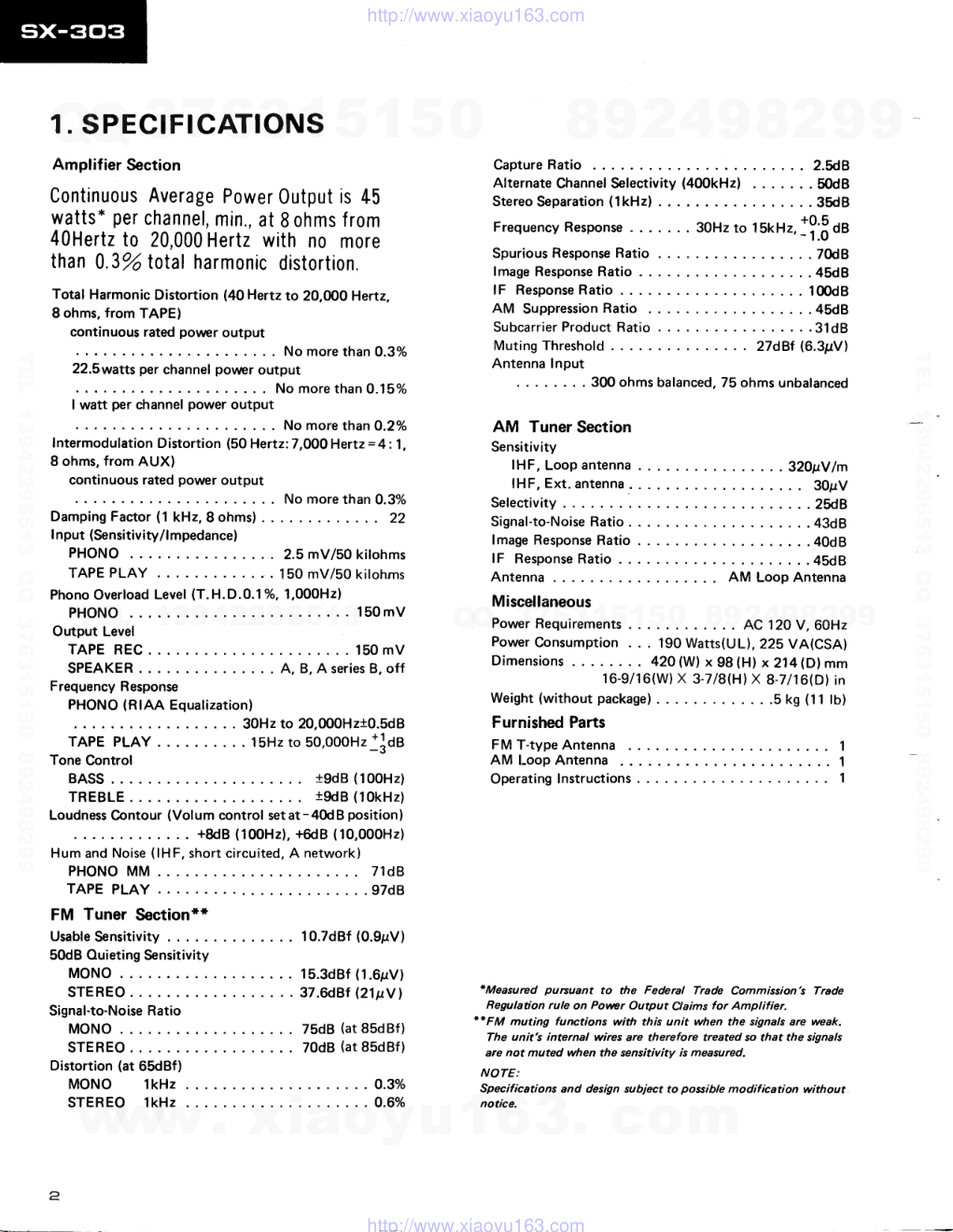
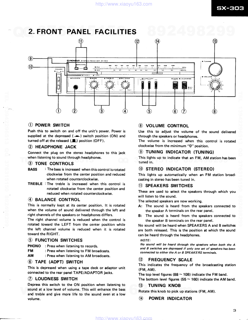
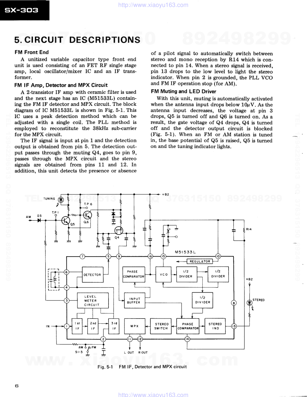
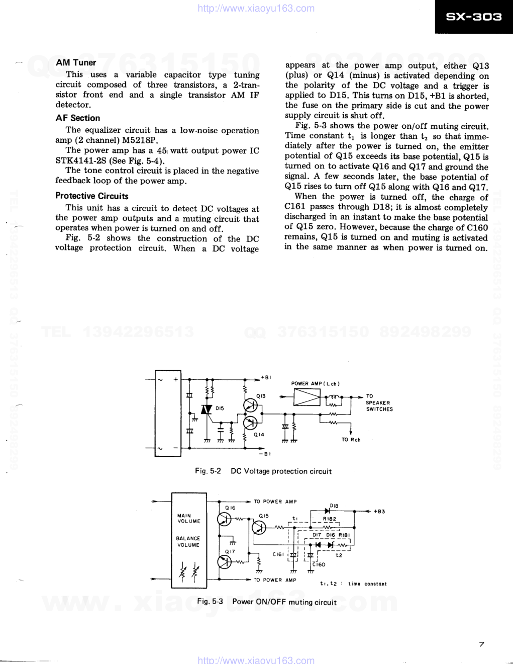
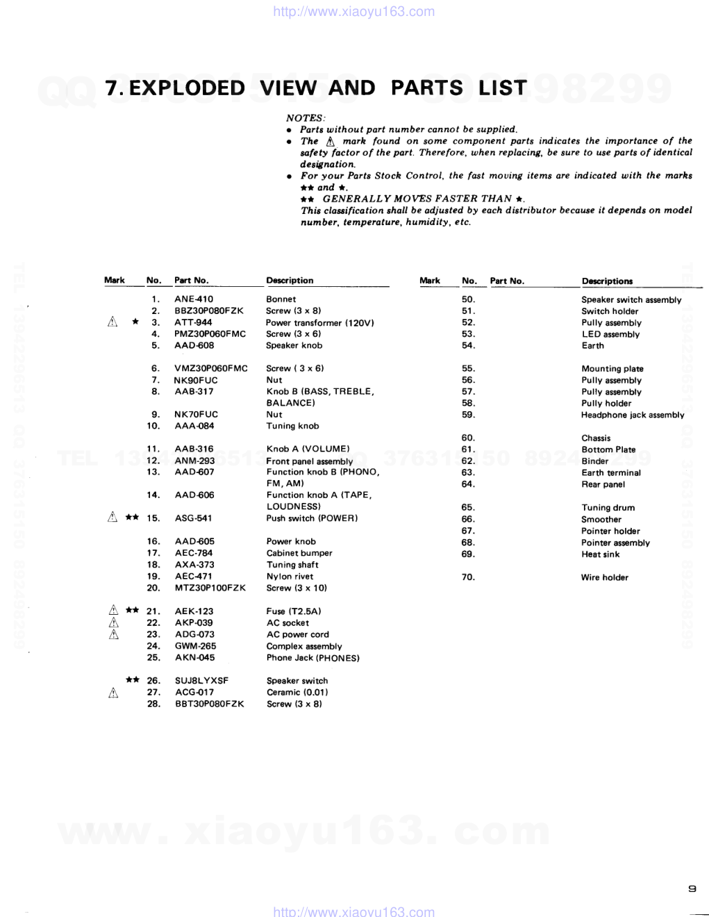
: - _ t I I (D rrloNEEFl' ORDER NO. ARP- 232-0 AM/FM STEREO RECETVER sixr3Gl3 o This service manual is applicable to the KU types. For servicing of the other types, please refer to the additional service manual. o Ge manuel d'instruction se refdre au mode de r6glage, en frangais. o Este manual de servicio trata del m6todo de ajuste escrito en espafiol. CONTENTS 1 . 2. 3. 4. 5 , 6. 7 . SPECIFICATIONS FRONT PANEL FACILITIES PARTS LOCATION BLOCK DIAGRAM CIRCUIT DESCRIPTIONS . PACKING EXPLODED VIEW AND PARTS LIST 2 3 4 5 6 8 9 8. P.C. BOARDS CONNECTION DIAGRAM 12 9. SCHEMATIC DIAGRAM 15 10. ELECTRICAL PARTS LIST . . 17 1 1 . D I A L C O R D S T R I N G I N G . . . . . . 1 9 1 2 . A D J U S T M E N T S . . . 2 0 nEcucr 22 A J U S T E . . . 2 4 PICINEEFI ELECTFICINIC CclFlPClFIATIClN 4-1, Meguno 1-chome, Mesuno-ku, Tokyo 1F3, Japan FIC|NEEFI ELECTFICINI€9 IUAAI lNC. 1925 E. Dorninguez St., Long Beech, Catifonnia gOB1O U.S.A. FfoNEEFI ELEcrFloNlc [EuFtoPEI N.v. Keerbengtean 1,e74o Bevenen, Betgium PI('NEEFf ELECTFICINIGB AUaTFIALIA FTY. t-lO. lzA-le4 Boundany Ftoad, Bnaeside, Victonier 819F, .Ausrnatia MODEL SX-303 (SX-303L) COMES IN FIVE VERSIONS DISTINGUISHED AS FOLLOWS: Model Voltage Remarks sx-303/KU AC120V only U.S.A. model sx-303/Kc AC120V only Canada model sx-303/s AC1 1 0V, 'l2OV ,22OV and 24OV (switchabte) General export model SX-303L/HE AC220V only European continent model with AM-LW band tuner sx-303L/HEZ AC220V only West germany model with AM-LW band tuner Y X O D E C . 1 9 8 2 P r i n t e d i n l a p a n www. xiaoyu163. com QQ 376315150 9 9 2 8 9 4 2 9 8 TEL 13942296513 9 9 2 8 9 4 2 9 8 0 5 1 5 1 3 6 7 3 Q Q TEL 13942296513 QQ 376315150 892498299 TEL 13942296513 QQ 376315150 892498299 http://www.xiaoyu163.com 1. SPECIFICATIONS Amplifier Section Continuous Average Power Output is 45 watts* per channel, min., at 8 ohms f rom 40Hertz to 20,000 Hertz with no more than 0.3o/o total harmonic distortion. Total Harmonic Distortion (40 Hertz to 20,fi)0 Hertz, I ohms, from TAPE) continuous rated povrrcr output No more than 0.3% 22.5watts per channel power output . . . . No more than O.15yo I watt per channel power output l*"r..irr"ii""oiri.r,i""it,i""r,rlrt,ill'iJir1"=t;?1, 8 ohms, from AUX) continuous rated power output No more than 0.3% Damping Factor (1 kHz, 8 ohms) 22 I nput (Sensitivity/l mpedance) P H O N O . . . . . 2 . s m V / S 0 k i l o h m s TAPE PLAY . . . 150 mV/50 kilohms Phono Overload Level (T.H.D.0.1%. 1,000H2) PHONO . . 150mV Output Level TAPE REC . 150 mV SPEAKER A, B, A series B, off Frequency Response PHONO (RIAA Equalization) . 30Hz to 20,000H2t0.5d8 TAPE PLAY 15Hz to SO,OOOHz+]OA Tone Control BASS . i9dB (100H2) TREBLE 19dB (10kHz) Loudness Contour (Volum control setat-40d8 position) . . +8dB (100H2), +6dB (10,000H2) Hum and Noise (lHF, short circuited, A network) P H O N O M M . . 7 1 d B T A P E P L A Y . . . . . . 9 7 d 8 FM Tuner Section** U s a b l e S e n s i t i v i t y . . . 1 0 . 7 d 8 f ( O . 9 p V ) 50dB Ouieting Sensitivity M O N O . . . 1 5 . 3 d B f ( 1 . 6 p V ) STEREO ..37.6d8f (211ty1 Signal-to-Noise Ratio M O N O . . . 7 5 d 8 ( a t 8 5 d B f ) STEREO . . 70dB (at 85dBf) Distortion (at 65dBf) M O N O l k H z . . . . 0 . 3 Y o S T E R E O l k H z . . . . O . 6 Y o C a p t u r e R a t i o . . . 2 . 5 d 8 Alternate Channel Selectivity (400kHzl . . 50dB Stereo Separation (lkHz) . . 35dB Frequency Response .. 30Hzto lSkHz,1ffOt S p u r i o u s R e s p o n s e R a t i o . . . . . . . 7 f t 8 l m a g e R e s p o n s e R a t i o . . . . 4 5 d 8 l F R e s p o n s e R a t i o . . . . . 1 0 0 d 8 A M S u p p r e s s i o n R a t i o . . . 4 5 d 8 S u b c a r r i e r P r o d u c t R a t i o . . . . . . . 3 1 d 8 Muting Threshold 27dBf (6.3pV) Antenna Input . . . 300 ohms balanced, 75 ohms unbalanced AM Tuner Section Sensitivity f HF, Loop antenna 32O1N lm lHF, Ext. antenna 30gV Selectivity . 2ft8 Signal-to-Noise Ratio . . . ..43d8 lmage Response Ratio ....40d8 l F R e s p o n s e R a t i o . . . . . . 4 5 d 8 Antenna AM Loop Antenna Miscellaneous Power Requirements . AC 120 V, 60Hz Power Consumption . . . 190 Watts(UL), 22S VA(CSA) Dimensions . . . 42O (W) x 98 lHl x 214 (D) mm 16-9/16(W) X 3-718(H) X 8-7116(D) in Weight (without package) . .5 kS (11 tO) Furnished Parts F M T - t y p e A n t e n n a . . . . . . 1 A M I - o o p A n t e n n a . . . . . . . . 1 Operating Instructions 1 'Measured pursuant to the Federal Trade Commission's Trade Regulation rule on Povver Output Claims for Amplifier. **FM muting functions with this unit when the signals are weak. The unit's internal wires are therefore treated so that the signals are not muted when the sensitivity is measured. NOTE: Specifications and design subject to possible modification without notice. 2 www. xiaoyu163. com QQ 376315150 9 9 2 8 9 4 2 9 8 TEL 13942296513 9 9 2 8 9 4 2 9 8 0 5 1 5 1 3 6 7 3 Q Q TEL 13942296513 QQ 376315150 892498299 TEL 13942296513 QQ 376315150 892498299 http://www.xiaoyu163.com 2. FRONT PANEL FACILITIES O powen swrrcH Push this to wrritch on and off the unit's power. Power is supplied at the depressed (r) switch position (ON) and turned off at the released (I) position (OFF). @ HenopHoNE JAcK Connect the plug on the stereo headphones to this jack when listening to sound through headphones. @ rorue coNTRoLs BASS : Thebass is increased whenthiscontrol isrotated clockwise from the center position and reduced when rotated counterclockwise. TREBLE : The treble is increased when this control is rotated clockwise from the center position and reduced when rotated counterclockwise. @ eeLeNcE coNTRoL This is normally kept at its center position. lt is rotated when the volume of sound delivered through the left and right channels of the speakers or headphones differs. The right channel volume is reduced when the control is rotatd toward the LEFT from the center position while the left channel volume is reduced when it is rotated toward the RIGHT. @ rurucrroN swrrcHEs PHONO : Press when listening to records. FM : Press when listening to FM broadcasts. AM : Press when listening to AM broadcasts. @ rape (ADPT) swrrcH This is depressed when using a tape deck or adaptor unit connected to the rear panel TAPE/ADAPTOR jacks. o LouorrrEss swtTcH Depress this svrritch to the ON position when listening to sound at a low level of volume. This will enhance the bass and treble and give more life to the sound even at a low volume. @ voluruE coNTRoL Use this to adjust the volume of the sound delivered through the speakers or headphones. The volume is increased when this control is rotated clockwise from the minimum "0" position. @ ruruIruG tNDIcAToR (TUNING) This lights up to indicate that an FM, AM station has been tuned in. @ sreneo rNDrcAToR (srEREo) This lights up automatically when an FM station broad- casting in stereo has been tuned in. @ speerERs swrrcHEs These are used to select the speakers through which you will listen to the sound. The selected speakers are now working. A: The sound is heard from the speakers connected to the speaker A terminals on the rear panel. B: The sound is heard from the speakers connected to the speaker B terminals on the rear panel. No sound will be heard when SPEAKERS A and B switches are both released. This is the position at which the sound can be heard through the headphones. NOTE: No rcund will be heard through the spakers when both the A and B switches are depressed if only one set of speakers has been connected to either the A or I SPEAKE RS terminals. @ FREoUENcY scALE This indicates the frequency of the broadcasting station (FM, AM). The top level figures (88 - 108) indicate the FM band. The bottom level figures (55 - 160) indicate the AM band. @ TUNTNG KNoB Rotate this knob to pick up stations (FM, AM). @ POWER |ND|CATOR www. xiaoyu163. com QQ 376315150 9 9 2 8 9 4 2 9 8 TEL 13942296513 9 9 2 8 9 4 2 9 8 0 5 1 5 1 3 6 7 3 Q Q TEL 13942296513 QQ 376315150 892498299 TEL 13942296513 QQ 376315150 892498299 http://www.xiaoyu163.com 3. PARTS LOCATION Front Panel View Speaker knob AAD60A Front panel assembly NOTES: . Parts without part nu ber connot be supplied. . The b morh found on aome component ports indicates the importonce of the sofety factor of the port- Thereforc, uhen replocing, be 6ure to use ports of id.enticol designation. . For your Potts Stock Control, the fost mot)ing items are indicated u)ith the moths ta and l. '' GENERALLY MOWS FASTER THAN '. Thb claesificotion shall be odjusted by eoch di;tributor becouse it deDends on model numbe f , te mperature, humidity, e tc. Bonnet A N E 4 l O ANM-293 AAD$O5 ..-":.n f\,- Knob A (vo LU1M E) A A B 3 1 6 Function knob A {TAPE, LOUDNESS) AAD€06 Function knob B ( P H O N O , F M , A M ) AAD607 Phone jack AKN-(X5 Knob B (BASS, TREBLE, BALANCE) AAB3I7 Rear Panel View Earth terminal Complex terminal AKX{73 Top View l\r*t Fuse (T2.5A) AEK-123 A** Push swirch (POWER' ASG-541 A ac socket AKP.O39 AWB{44 ** tc M5153L Switch assembly www. xiaoyu163. com QQ 376315150 9 9 2 8 9 4 2 9 8 TEL 13942296513 9 9 2 8 9 4 2 9 8 0 5 1 5 1 3 6 7 3 Q Q TEL 13942296513 QQ 376315150 892498299 TEL 13942296513 QQ 376315150 892498299 http://www.xiaoyu163.com 4. BLOCK DIAGRAM F R O N T E N D ( 1 / 3 ) T | 3OOO . B A L F M I L r rrupar l- cND AM I LOOP L A N T FM M I X A M P L E D D R I V E R FM MUTE AM FRONT ENO [5dtl sr-l PHONO F M ( L c h ) F M ( R c h ) l- crav Lch REC i- ,"o"o f eiror,ro Rch REC l- ".o" s r - 4 TAPE (t/? ) s r - 5 LO U ON ESS ( ? / 2 ) TONE CONTROL vR2-2,2-3 EQUALIZER AMP lzsmrl t'Ery I pHoNEs TO r_- 134,4/41 R c h SPEAKE RS ac r20v 60 Hr + 9 2 ( 15.4V s 2 - 2 S P - B ( v z l s 2 - l S P - A l t / 2 ) l I " o ] , , ^ SI-l : FUt{CTION (PHOtlO) S I - 2 : F U N C T I O N { F M ) s r - 5 : F U t { c T r o N ( A M ) SI-4 : TAPE MONITOR sr-5: LouoNEss 9!L- oFF oN -.9!E oN -.g_Eq ON --qEE or -_q!! S 2 . I : S P E A K E R S S 2 . 2 : S P E A X E R S 0 7 I _9_l!- - oFF !-!L - oFF F M . I F A M P FT.I IF,/OET MPX RE6ULA. r f r R t x METER OETECTOR r-;1-l rcr i lrJ i I t f r I l t / 2 ) | ( t / 4 ) ffi--D"t o='""o' P O W E R A M P s r - 4 s r - 5 | 2/2 t (2/2 ) A M I F A M P + 8 2 A M 04 POWER ON,/OFF MUTING POWER SUPPLY A PROTECTOR s r o r i P o W E R o i l - o F F 5 www. xiaoyu163. com QQ 376315150 9 9 2 8 9 4 2 9 8 TEL 13942296513 9 9 2 8 9 4 2 9 8 0 5 1 5 1 3 6 7 3 Q Q TEL 13942296513 QQ 376315150 892498299 TEL 13942296513 QQ 376315150 892498299 http://www.xiaoyu163.com 5. CIRCUIT DESCRIPTIONS FM Front End A unitized variable capacitor type front end unit is used consisting of an FET RF single stage amp, local oscillator/mixer IC and an IF trans- former. FM lF Amp, Detector and MPX Circuit A 2-transistor IF amp with ceramic filter is used and the next stage has an IC (M51533L) contain- ing the FM IF detdctor and MPX circuit. The block diagram of IC M51533L is shown in Fig. 5-1. This IC uses a peak detection method which can be adjusted with a single coil. The PLL method is employed to reconstitute the 38kHz sub-carrier for the MPX circuit. The IF signal is input at pin 1 and the detection output is obtained from pin 5. The detection out- put passes through the muting Q4, goes to pin 9, passes through the MPX circuit and the stereo signals are obtained frorn pins 11 and 1'2. In addition, this unit detects the presence or absence I L OUT R OUT of a pilot signal to automatically switch between stereo and mono reception by R14 which is con- nected to pin 14. When a stereo signal is received, pin 13 drops to the low level to light the stereo indicator. When pin 2 is grounded, the PLL VCO and FM IF operation stop (for AM). FM Muting and LED Driver With this unit, muting is automatically activated when the antenna input drops below 10pV. As the antenna input decreases, the voltage at pin 3 drops, Q5 is turned off and Q6 is turned on. As a result, the gate voltage of Q4 drops, Q4 is turned off and the detector output circuit is blocked (Fig. 5-1). When an FM or AM station is tuned in, the base potential of Q5 is raised, Q5 is turned on and the tuning indicator lights. n r t r F ? ? | O E T E C T O R I N P U T B U F F E R L E V E L M E T E R C I R C U I T S T E R E O 5 W r T C H Fig.5-1 FM lF, Detector and MPX circuit www. xiaoyu163. com QQ 376315150 9 9 2 8 9 4 2 9 8 TEL 13942296513 9 9 2 8 9 4 2 9 8 0 5 1 5 1 3 6 7 3 Q Q TEL 13942296513 QQ 376315150 892498299 TEL 13942296513 QQ 376315150 892498299 http://www.xiaoyu163.com AM Tuner This uses a variable capacitor type tuning circuit composed of three transistors, a 2-fuan- sistor front end and a single transistor AM IF detector. AF Section The equalizer circuit has a low-noise operation amp (2 channel) M5218P. The power amp has a 45 watt output power IC STK4141-2S (See Fig. 5-4). The tone control circuit is placed in the negative feedback loop of the power amp. Protective Circuits This unit has a circuit to detect DC voltages at the power amp outputs and a muting circuit that operates when power is turned on and off. Fig. 5-2 shows the construction of the DC voltage protection circuit. When a DC voltage appears at the power amp output, either Q13 (plus) or Q14 (minus) is activated depending on the polarity of the DC voltage and a trigger is applied to D15. This turns on D15, +81 is shorted, the fuse on the primary side is cut and the power supply circuit is shut off. Fig. 5-3 shows the power on/off muting circuit. Time constant t1 is longer than t2 so that imme- diately after the power is turned on, the emitter potential of Q15 exceeds its base potential, Q15 is turned on to activate Q16 and Q17 and ground the signal. A few seconds later, the base potential of Q15 rises to turn off Q15 along with Q16 and e1Z. When the power is turned off, the charge of C161 passes through D18; it is almost completely discharged in an instant to make the base potential of Q15 zero. However, because the charge of C160 remains, Q15 is turned on and muting is activated in the same manner as when power is turned on. TO SPEAKE R SWITCHES Fig. 5-2 DC Voltage protection circuit T O P O W E R A M P t r , r 2 POWER AMP ( L ch ) Fig. 5-3 Power ON/OFF muting circuit const ont www. xiaoyu163. com QQ 376315150 9 9 2 8 9 4 2 9 8 TEL 13942296513 9 9 2 8 9 4 2 9 8 0 5 1 5 1 3 6 7 3 Q Q TEL 13942296513 QQ 376315150 892498299 TEL 13942296513 QQ 376315150 892498299 http://www.xiaoyu163.com I rN r(+)l 2 r N l ( - ) 6. PACKING t a OUT 2 Equivalent circuit of power lC r 8 t N 2 ( + ) t 7 r N 2 ( - ) G N D 6 8 MUTING Fis.5-4 9 VEE fi II . J t 6 G N to OUT I Mark No. Part No. Doscription 1 . 2. 3. 4. 5 . AHA.335 AR8526 ATB{76 ADH.OOS AHE-107 Side pad Operating instructions (English ) Loop antenna assembly T-type antenna Packing case a www. xiaoyu163. com QQ 376315150 9 9 2 8 9 4 2 9 8 TEL 13942296513 9 9 2 8 9 4 2 9 8 0 5 1 5 1 3 6 7 3 Q Q TEL 13942296513 QQ 376315150 892498299 TEL 13942296513 QQ 376315150 892498299 http://www.xiaoyu163.com T.EXPLODED VIEW AND PARTS LIST NO?ES: o Parts without part number cannot be supplied. o The S marh found on some component parts indicates the importance of the safety factor of the part. Therefore, when replacing, be sure to use parts of identicol designotion. o For your Parts Stoch Control, the fast mouing items are indicated with the morhs t* ond *. *T GENERALLY MOWS TASTER THAN ). This classification shall be adjusted by each distributor because it depends on model number, temperaturc, humidity, e tc. lVlark No. Part No. Decriptions Mark No. Part No. Description 1. ANE410 Bonnet 2. BBZ30P080FZK Screw (3 x 8) A * 3. ATT-944 Power transformer {120V} 4. PMZ30PO60FMC Screw (3 x 6l 5, AAD€O8 Speaker knob 6. VMZ30P06OFMC Screw ( 3 x 6 ) 7. NK9OFUC Nut 8. AAB-317 Knob B {BASS, TREBLE, BALANCE} 9. NKT0FUC Nut 10. AAAO84 Tuning knob 11. A48-316 Knob A (VOLUME) 12. ANM-293 Front panel assembly 13. AAD€07 Function knob B (PHONO, FM, AM ) 14. AAD€06 Function knob A (TAPE. LOUDNESS} A ** ts. ASG-541 Pushswitch (POWER) 16. AAD€05 Power knob 17. AEC-784 Cabinet bumper 18. AXA-373 Tuning shaft 19. AEC471 Nylon rivet 20. MTZ3OPIOOFZK Screw (3 x 1O) a ** z't. AEK-123 Fuse (T2.5A) A 22. AKP-039 AC socket A 23. ADG-073 Ac power cord 24. GWM-265 Complex assembly 25, AKN-045 Phone Jack (PHONES) ** 26. SUJSLYXSF Speaker switch A 27. ACGO17 Ceramic (0.01 ) 24. BBT30P080FZK Screw (3 x 8) 50. 51 . 52. 53. 54. 55. 56. 57. 58. 59. 60. 6 1 . 62. 63. 64. Speaker switch assembly Switch holder Pully assembly LED assembly Earth Mounting plate Pully assembly Pully assembly Pully holder Headphone jack assembly Chassis Bottom Plate Binder Earth terminal Rear panel Tuning drum Smoother Pointer holder Pointer assembly Heat sink Wire holder 65. 66. 67. 68. 69. I www. xiaoyu163. com QQ 376315150 9 9 2 8 9 4 2 9 8 TEL 13942296513 9 9 2 8 9 4 2 9 8 0 5 1 5 1 3 6 7 3 Q Q TEL 13942296513 QQ 376315150 892498299 TEL 13942296513 QQ 376315150 892498299 http://www.xiaoyu163.com A 3 2 1 /dt"' /r"t" B 2 t e @ <( @ \ - - .Sr 8l ?'v ,6rff h<; C K \@ l-F EA @ @ t l \gw@ AYZ+'-' N 7 - \ "JFi /F/ \ D 3 l 2 2 1 t-'-' @h \ 2z\a i \lg www. xiaoyu163. com QQ 376315150 9 9 2 8 9 4 2 9 8 TEL 13942296513 9 9 2 8 9 4 2 9 8 0 5 1 5 1 3 6 7 3 Q Q TEL 13942296513 QQ 376315150 892498299 TEL 13942296513 QQ 376315150 892498299 http://www.xiaoyu163.com 4 A { 2 )\ l-J-\ B C D 6 # S-d::) www. xiaoyu163. com QQ 376315150 9 9 2 8 9 4 2 9 8 TEL 13942296513 9 9 2 8 9 4 2 9 8 0 5 1 5 1 3 6 7 3 Q Q TEL 13942296513 QQ 376315150 892498299 TEL 13942296513 QQ 376315150 892498299 http://www.xiaoyu163.com 3 2 I DIAGRAM 8. P.C. BOARDS CONNECTION External Appearances of Transistors and lC's A 2SA 726S Lot No h F E Type No 2SC1923 TYPe No h : e 2SC 461 COMPLEX Ass'y GWM - Q3 02 Q4 01 - 2SK34 B x .jj44ru# D 1 3 2 .., *.-ffi rvor No--ffi,,...-Lot No '""]fi!rvpeNo rvPe*-uh^" 4[[" 2SD 880 2SD 313 JA1Ol JC501 ,rO"*"-ffi n"-1ffi-Lot No C : u \ 2SK 246 Type No 2SA1115 zSC2603 Lot sTK4171-2S M5218P NJM4558D ."m* M51533L I Dss LED Ass'y www. xiaoyu163. com QQ 376315150 9 9 2 8 9 4 2 9 8 TEL 13942296513 9 9 2 8 9 4 2 9 8 0 5 1 5 1 3 6 7 3 Q Q TEL 13942296513 QQ 376315150 892498299 TEL 13942296513 QQ 376315150 892498299 http://www.xiaoyu163.com 6 5 4 o16 oil Ql7 Q 7 Q 9 q 8 Q r O ( Ass'y GWM - 265 Q4 0r Q6 05 S P E A K E R A ,6.'ff$ :: #iE; l:. ,. .. . -t q : . i : ' . ' : ! e " r ? , , ' : ' a ! 6 q : ! i e : ' . i , 6 . ; : : : : : . ' l f l i o r a : S ; , : : +-tfi I i : ; ti'J' q ,* ": I ClSr U I i g Czlze{T S I a i 6i;! : 4 i 6 q S l 6 € . ; . ; : : I { ' : : r ' - | . o : : qll jlrlt rqi ia iq ;i ?i :lin: ::::: : e l , " - l'.'rigr i;*ilil; fl@8€r gY;r ir: I '\.i? .:ry " r . , u J : . # f , l : i ; ; ; r ; ; r . * | , = " " : " . _ , : : p ; I g ; ' - l F $ ' r I l l t " ? . ' T " i l l I | | t t l l " t + + +t tL{ * . 4 b l , : { * Eq"- ffi. **"** ,*"'i'i1#..,"ffi .7 ":*2rolro t F i:: : ", J'sc ^. r,. ? tztzs I dp+ro { * " cl5? E ct'a& 3 rffi;i ""'rXof,i" 3t 1 z J c $ o l e r r 2 S A 9 9 2 2 5 0 8 8 0 J A I O l ' : l - - : . , , . ' : . + ; ' $ , t t d f l I t J u 3 . t ':*$ i t $ p d ffi1,'"" -o. M 5 1 5 3 3 L M 5 2 1 8 P s T K 4 1 7 r - 2 S A2 W'l-,67s .,L. ,.s; DIS--:,.. 8cR6A 04 z-rX}.Bt-"'- .'"",8O.' sz- 02 0 8 K z L 1 4 P . l ' 3 , ' l : : l : , ' D 9 R 8 4 0 2 ' , I Frr2 - - aSOtl r 6 5 4 www. xiaoyu163. com QQ 376315150 9 9 2 8 9 4 2 9 8 TEL 13942296513 9 9 2 8 9 4 2 9 8 0 5 1 5 1 3 6 7 3 Q Q TEL 13942296513 QQ 376315150 892498299 TEL 13942296513 QQ 376315150 892498299 http://www.xiaoyu163.com I B 7 NOTE: The indicated semiconductors are representatiue ones only. Other olternatiue semiconductors may be used and are listed in the parts list. HEADPHONE JACK Ass'y c50l 0.0t /Ac t25 ACG-0t7 Sl0l : PoWER ASG- 54 | SWITCHED UNSTTITCHED r00w MAX . r00w MAX. AC f20V 60Hz - $ t ' ' ' , ; j : s d;i rP boi j " Ptls iff - t IB .R-r4a- c.ll.o cr28 RlL0. I'l T.-T.TF* J'g T,:$.gs* I B 7 aEL-405 L-tfip oz POINTER Ass'y www. xiaoyu163. com QQ 376315150 9 9 2 8 9 4 2 9 8 TEL 13942296513 9 9 2 8 9 4 2 9 8 0 5 1 5 1 3 6 7 3 Q Q TEL 13942296513 QQ 376315150 892498299 TEL 13942296513 QQ 376315150 892498299 http://www.xiaoyu163.com 1 3 2 g.SCHEMATIC DIAGRAM 1- '_ 3oo:jAl : " 1 Lz5o UNBAL L nro Il5o'vl [- PLAY TAPE - REC PHONO I-r.s;tl ,o[ *'" L *o, II r-r, CoMPLEX Ass'Y (1/3) GwM-265 [ *,. r, F M I F A M P I I - c 2 - I e a { o o t 1 - - - - - - . 1 _ ) 4 7 o f h w r r--- -Iq IlgLr-q!'.|g -l1l1)- -1tB---o4 i I i-1: I | -^^^ i s'et 7 | .. o.o' c33 . 2 2 / 2 5 R 5 0 330 c2a to/5 + + c2( o.0 R45 6.8 r Q 7 . I A M F R O N T C l 5 2 r - o.o22 T,r7 R 4 3 1 5 I c38 + L3 l m H = c 3 o I lzop ,r7 1 R 4 l r . 5 k \?2,38* oo4T ,/25 + I R55 c42 r 47k o.ol I 7 v ) c39 iFe I , ) A M I F M L q e F A M P - - ,:;1?" Drz Dr6 !59 f Rr83 471 Q I I P O W E R A M P G N D M U T I N G V e e 3 4 5 6 7 A 9 c i l 3 --{ F rOOp R r23 r-- A T E - O 5 8 A T B - O 8 5 A T B - O 8 4 A T F - O 8 3 A T F . O 8 4 a c r - t 6 2 a c T - 6 0 2 R H B S A V S 5 O 2 Q 1 , 2 , 7 , 9 2 S C 4 6 1 Q 4 2 5 K 2 4 6 Q 5 , 6 , r 3 , 1 6 , 1 7 J C 5 0 1 Q 8 2 5 A 9 9 ? Q 1 2 2 S D 8 8 O Q 1 4 , r 5 J A r O l Q 3 M 5 1 5 3 3 L q r o M 5 2 r I P q f I s T K 4 1 7 1 - 2 5 o 1 , 3 , 1 2 , 1 7 , 1 8 r N 4 l 4 8 D 2 W Z - O 7 5 D 4 2 - 1 K 2 6 1 D 8 D 9 Dil K Z L 1 4 0 0 t 3 . 1 4 1 0 E 2 F O R 8 4 0 2 0 r 5 B C R 6 A M - 4 w z - 1 3 0 0 1 6 S Z - O 2 7 1_ J c36 T zzc 7r' ini ih*Ii l1'* L - - - - J FM FRONT ENO ( 3 / 3 ) 3 2 1 www. xiaoyu163. com QQ 376315150 9 9 2 8 9 4 2 9 8 TEL 13942296513 9 9 2 8 9 4 2 9 8 0 5 1 5 1 3 6 7 3 Q Q TEL 13942296513 QQ 376315150 892498299 TEL 13942296513 QQ 376315150 892498299 http://www.xiaoyu163.com 5 4 fi^, ,, ;r32 20Op R144 4 . 7 k r34 i600p l L r 4 0 0 , t 3 , 1 4 1 C - E ? F O 1 4 0 2 D l 5 B CR6 AM - 4 l - r 3 0 D 1 6 S Z - O 2 7 D 7 A E L - 4 O 5 I -"a-l I ct? o. | /5o | *@--' : L--tl"rr - -J Ass'y F U N C T I O N ( P H O N O ) F U N C T I O N ( F M ) F U N C T I O N ( A M ) T A P E M O N I T O R L O U D N E S S SWITCHES: COMPLEX s r - 1 : s l - 2 : s 1 - 3 : s r - 4 : s r - 5 : P O I N T E R A s s ' y S W I T C H A s s ' y S 2 - 1 : S P E A K E R S ( A ) S 2 - 2 : S P E A K E R S ( B ) O U T S I D E O F P C B O A R D S I O I : P O W E R ' \ _ v l _ (otAL Po|l{TER'- J Q t 3 , l 4 P R O T E C T O R V:r 9 "f [ , , o , Rt7 7 R r79 r 5 0 r 8 0 COMPLEX Ass'y ( 2/3 ) - - - - _ - -J 6 5 4 - r---l L i Q 3 FM IF/ DET A MPX c2l o.22/50 6 O F F O N - O F F O N _ O F F O N _ O F F O N _ O F F O N - O F F ON - OF F O N - O F F The underlined indicates the switch position. SWITCHEO UNSWITCH€O roow HAx roow MAx NOTE: The indicated semiconductors are representatiue ones only. Other alternative semiconductors may be used and are listed in the parfs llsf. 1 . R E S I S T O R S : f ndicated in a,%W,'/eW,t5i6 tolerance unless otherwise noted k : ko, M : M a , ( F ) : r 1 % , ( G ) : t 2 % , ( K ) : t 1 0 % ( M l : t 2 O % t o l e r a n c e 2 . C A P A C I T O R S : Indicated in capacity (ltF)/voltage (V) unless otherwise noted p : pF Indication without voltage is 50V except electrolytic capacitor. 3 , V O L T A G E . C U R R E N T : [ _ - l ' s i g n a l v o l t a g e a t ( 4 0 W + 4 O W 8 o ) o u t p u t ( l k H z ] f_] , DC voltage (V) at no input signal Value in ( ) is DC voltage at ratd power. 4 . O T H E R S : rf: Signal route. @ : Adjusting point. The I mark found on some component parts indicates the im- portance of the safety factor of the part. Therefore, when replacing, be zure to use parts of identical designation. This is the basic schematic diagram, but the actual circuit may vary due to improvements in design. LED Ass'y 161 f--^-*--] I D 5 A E L - 4 O 6 | ; D6 AEL-4O7 | www. xiaoyu163. com QQ 376315150 9 9 2 8 9 4 2 9 8 TEL 13942296513 9 9 2 8 9 4 2 9 8 0 5 1 5 1 3 6 7 3 Q Q TEL 13942296513 QQ 376315150 892498299 TEL 13942296513 QQ 376315150 892498299 http://www.xiaoyu163.com 10. ELECTRICAL PARTS LIST NO?ES: o When ordering resisfons, first conuert resistance wlues into code form as shown in the following exomples. Ex. 1 l4rhen there are 2 effectiue digits (any digit apart from O), such aa 560 ohm and 47k ohm (tolerance is shown by J = 5V", and K - IOVo). 5 6 0 { 1 5 6 x L O t 5 6 1 . . . . R D % P S H @ | m J 4 7 h a 4 7 x 1 0 ' 4 7 3 . . . . R D T I P S E D A I E ! / - - Ex. 2 l4then there are 3 effective digits (such as in high precision metal film recis- tors). 5.62ha 562 x 100 5621. . . . AN%SR E6Emr' c The b, marh found on some component parts indicates the importance of the safety factor of the part. Therefore, when replacing, be sure to use ports of identical designation. c For your Parts Stoch Control, the fast mouing items are indicated with the marks ** and *- ** GENERALLY MOVES FASTER THAN *. This classificotion shall be adjusted by each distributor because it depends on model number , temperature, humidity, etc. 0.5{2 t n Miscellaneous Parts List P.C. BOARD ASSEMBLIES Mark Part No. 0 R 5 . . R N 2 H O E E K olo . . asrPo0cK Part No. Symbol & Description Symbol & Dercription CEA 1O1M 35L CEA 221M 1OL CEA 471 M 6L CEANL 2R2M 50 coMA 122K 50 coMA 562K 50 coMA 153K 50 coMA 333K 50 coMA 242J 50 coMA 822J 50 coMLA 124K 50 cosA 182J 50 cosA 5t 1J50 ccDuJ o50c 50 ccDsL 270J 50 ccDsL 121J 50 ccDsL t0lJ 50 ccDsL 221J 50 ccDcH 150J 50 ccDcH 220J 50 CKDYF 1032 50 CKDYF 223250 CKDYX 473M25 CKDYB 222K50 ACG{19 cl50 cl47, C160 c 1 4 3 c 1 0 1 , c l 0 2 c l 3 1 . C 1 3 2 c 1 5 , C 1 3 3 , C 1 3 4 c19, C20 c127,C128 cl07, c108 c 1 0 9 . c 1 1 0 c129, Cl30 c l 8 c34 c7 c125, C126 c30 c 1 1 3 . C 1 1 4 , C 1 1 7 , C l 1 8 cl03, c104 c24 c36 c2-c5. c23, C29, C32, C40, C42 c 6 , c 8 , c l 3 , C 4 3 , C l 1 5 , C l 1 6 , c144,C152, C156, Cl57 c39, C141 , C142 c41 Cl48 ceramic (0.01 /1 50V ) GWM.265 OTHERS I\lark Part No. Complex assembly Headphone lack assembly LED assembly Pointer assembly Switch assembly Symbol & Description AAAAAA * ATT-944 ** ASG-541 ACG{17 ** AEK-'|23 ADGO73 AKP.O39 T1 01 s101 c501 F U l O 1 Power transformer (1 20Vl Push switch (POWERI Ceramic (0.01/AC125V) Fuse (T2.5A) AC power cord AC socket Complex Assembly (GWM-265) CAPACITORS Mark P.rt No. Symbol & Dercription ACH-252 CE A 1 0 1M sOL CEA R22M sOL CE A O RlM sOL CEA R47M sOL CEA OlOM sOL CEA lOOM sOL CEA 22OM 25L CEA 47OM lOL CEA 47OM 25L CE A 1 0 1M 25L Cl 45, C146 Electrolytic (470OI5OV) c1 39 c11, C21 , C22 c12 c 1 0 c14, C17, C27, C111, C112, c123,C'�t24 c16, C2a, C31, C38, C119, c120, c138, Cl54, C155, C161 c33,C121, C122 c26, Cl05, Cl06 c135, C136, C137, C151, C153 c9, c37, Cl40 - www. xiaoyu163. com QQ 376315150 9 9 2 8 9 4 2 9 8 TEL 13942296513 9 9 2 8 9 4 2 9 8 0 5 1 5 1 3 6 7 3 Q Q TEL 13942296513 QQ 376315150 892498299 TEL 13942296513 QQ 376315150 892498299 http://www.xiaoyu163.com RESISTORS Note: Mark COILS AND TRANSFORMERS Mark Part No. When ordering resistors, conuert the resistance value into code form, and then rewrite the part no. as before. Part No. SYmbol & Doscription Symbol & Description SEMICONDUCTORS Mark Part No. VRl Volume (250k) VR2 Volume assembly (100kx2, 1Ml VB3 Semi-fixed (Skl R166 Wire-wound lO.22x2,2Wl R187 Carboncomposition l2.2M,1l2wl R12,8155-R159, R173 R35, 836, Rl15, Rl16, R147-R 1 5 4 , R160-R165, 8167, R168. R172,R174, R175, R180 Other resistors Symbol & Doscriptaon * * * ACT-162 ACT€02 RHBSAVS5O2 ACN-1 31 ACN-140 RD'I/4PMFL trOO RD':4PM OOD RD1/8PM Do tr J ATH{53 ATH.O58 ATEO58 ATB-085 ATB{84 ATFO83 ATF{84 OTHERS Mark Part No. Ll, L2 AF choke coil L3 Micro inductor T1 FM detector transformer T2 AM antenna coil T3 AM oscillator coil F1 , F2 FM ceramic f ilter F3 AM ceramic f ilter Symbol & Dercription AA A ** ASG-412 AWB.O44 AKX{73 AEC-940 Sl Push switch (FUNCTION, TAPE, LOUDNESS} FM Front€nd Complex terminal R ivet ** ** ** ** *t 2SC461 (25C1 9231 sTK4171-2S M51533L-B M5218 P (NJM4558DX) 2SK246 (25K34) 25D880 (2SD313) 2S4992 (25A7265) JC501 (2SC2603) J A 10 1 ( 2 S A 1 1 1 5 1 1 N4148 (us1 0351 ( 1 52076) ( 1 S1 sssl RB4O2 1 OE2FD BCR64M4 2-1K261 KZL140 s2{�27 wz-130 (MZ-1301 w2475 (MZ-075) o1, 02, 07, 09 ol 1 o3 0 1 0 o4 412 o8 05, 06, 01 3, 016, 01 7 0 1 4 , 0 1 5 D l , D 3 , D 1 2 , D 1 7 , D 1 8 AKN{45 RDY4PM ODtr J LED Assembly Mark Part No. Phone jack (PHONES) R 1 7 6 - R 1 7 9 Symbol & Description PBZ30ZP060FMC Screw (3 x 6l ABA-271 Screw Headphone Jack Assembly Mark Part No. Symbol & Dercription A * * A * * * AEL-406 * AEL-407 Pointer Assembly Mark Part No. D5 (Red STEREO) D6 (Green TUNING) Symbol & D€scription A * A * A * * * * * D9 D 1 3 , D l 4 D 1 5 D4 D8 D l 6 D l 1 D2 * AEL-405 A A F . l 1 8 Switch Assembly Mark Part No. D7 (Red) Pointer Symbol & D$cription ** SUJSLYXSF 52 Push switch (SPEAKERS) www. xiaoyu163. com QQ 376315150 9 9 2 8 9 4 2 9 8 TEL 13942296513 9 9 2 8 9 4 2 9 8 0 5 1 5 1 3 6 7 3 Q Q TEL 13942296513 QQ 376315150 892498299 TEL 13942296513 QQ 376315150 892498299 http://www.xiaoyu163.com 1 1. DIAL CORD STRINGING 1. Remove the bonnet. 2. Remove the tuning drum from the shaft of the tuning capacitor. 3. Tie one end of the cord to the stud A located inside the tuning drum. 4. Rotate the tuning capacitor right around until the rotor blades are fully intermeshed. 5. Secure the tuning drum back onto the tuning capacitor shaft, making sure that the securing screw B faces directly upward. 6. Pass the cord out through the small opening in the circumference of the tuning drum (see diagram), and then take it over pulleys C and D in that sequence. 7. Wind the cord around the tuning shaft 3 times. 8. Pass it over pulley E, wind it around the tuning drum 1 time, and finally tie it to the spring hook F so that it is tensioned. Dial pointer 9. Tum the tuning shaft, and check that the cord moves smoothly. 10. Cut off any excess cord. 11. T\rm the tuning shaft counter-clockwise as far as it will go. 12. Align the dial pointer with the starting point of the dial scale, and then pass the cord over it. 13. Check that the dial pointer is in line with the starting point of the dial scale. 14. Finally apply the locking paint to the cord securing positions (stud A and spring hook F) and the dial pointer connection. I I Dial pointer Starting point O nvr I U www. xiaoyu163. com QQ 376315150 9 9 2 8 9 4 2 9 8 TEL 13942296513 9 9 2 8 9 4 2 9 8 0 5 1 5 1 3 6 7 3 Q Q TEL 13942296513 QQ 376315150 892498299 TEL 13942296513 QQ 376315150 892498299 http://www.xiaoyu163.com 12. ADJUSTMENTS FM Tuner Section o Check that the dial pointer indicates a starting point. o Connect the SIGNAL meter between terminal no. 1 of complex assembly and the ground. o In principle, no adjustment should be made on FM tracking. (See page 21, if necessary.) o Set the FM switch to ON and connect terminal no. 6 to the ground. NOTE: Connect the MPX SG to the FM SG external modulator terminal and set the mod.ulation of Main (lhHz, L+R) !67.5hH2 deuiation, Pilot (19kHz) !7.1kHz deuiation. Ad.justment points in brackets are for SX-303L (Low Wave) only. Step FM SG {400H2, t75kHz deviation} Position of dial pointor Adiustmant point Adiustmont procodure Frequency Lcvcl '| 98MHz 66d8 98MHz t l Set the output of the REC OUT terminal to the maximum value. 2. 98MHz 46dB 98MHz T6 Set the SIGNAL meter to the maximum value 3. 98MHz 66dB 98MHz T 1 Adiust the output of the REC OUT terminal distortion to the minimum level. 4. Disconnect terminal no. 6 from the ground. 5. 98MHz I OOae Not modulated 98MHz VR3 Set the signal of the terminal no. 4 to 76kHz (t200Hz) 6. 98MHz r Stereo m 66dB odulation 98MHz T6 (within tgOo ) Minimize the distortion of the REC OUT terminal signal 20 Fig. 1 1-1 Adjustment points www. xiaoyu163. com QQ 376315150 9 9 2 8 9 4 2 9 8 TEL 13942296513 9 9 2 8 9 4 2 9 8 0 5 1 5 1 3 6 7 3 Q Q TEL 13942296513 QQ 376315150 892498299 TEL 13942296513 QQ 376315150 892498299 http://www.xiaoyu163.com Step FM SG (tl00Hz, r?SkHz doviationl Posation of dial pointer Adiustmoni poant Adiustmont procodure Frequenqy Level 1 106MHz 1 odB l O6MHz TC7 Set the SIGNAL meter to the maximum value. 2 . TC5 3. TC6 4. Confirm that the dial pointer does not ger out of position at 106MHz and 98MHz. FM tracking NOTE: (For SX-303L/HEZ) . When 87.6MHz can not be receiued with this unit, adjust the oscillator (TC7) and then it can be receiued. It is prohibited to receiue 87.2MHz or below and so after hauing ad,justed the oscillator, mahe eure that it does not receive 87.2MHz or below. AM Tuner Section o Check that the dial pointer indicates a starting point. o Tum ON the MW switch. o Connect the SIGNAL meter between the terminal no. 1 of complex assembly and the gxound. Long Wave Section (SX-303L/HE, HEZ only) o Set the AM BAND switch to the LW position. Step AM SG (400H2, 30% modulataonl Position of dial pointer Adlustment point Adjustment procedure Frequency I Lwel 1 1 395kHz 1 00dB 1 395kHz TC3 Set the SIGNAL meter to the maximum value. 2 . 603kHz 1 00dB 603kHz I J J . Set the AM SG to 30dB output level, repeat steps I to 2 above. 4 . 1 395kHz 3 0 d B l r g g s r H z l r c c Set the SIGNAL meter to the maximum value. 3 0 d B l e O a t H z i - t 2 5. 603kHz o . Repeat steps 4 to 5 until maximum sensitivity is attained. Setp AM SG (40OHz, 30% modulationl Position of dial pointor Adlustmsnt point Adjustment procedure Frequency Level 1 254kHz 1 00dB 254kHz TC2 Set the SIGNAL meter to the maximum value. 2 . 1 64kHz 1 00dB 'l64kH z I J 3 . Set the AM SG to 30dB output level, repeat steps 1 to 2 above. 4. 254kHz 50dB 254kHz TCI Set the SIGNAL meter to the maximum value 5 . 1 64kHz 50dB 1 64kHz T4 6. Repeat steps 4 to 5 until maximum sensitivity is attained www. xiaoyu163. com QQ 376315150 9 9 2 8 9 4 2 9 8 TEL 13942296513 9 9 2 8 9 4 2 9 8 0 5 1 5 1 3 6 7 3 Q Q TEL 13942296513 QQ 376315150 892498299 TEL 13942296513 QQ 376315150 892498299 http://www.xiaoyu163.com 12. REGLAGE Section Tuner MF o V6rifier que I'aiguille du cadran indique un point de d6part. o Brancher le mesureur de signal sur la borne no 1 et la masse du montage de I'ensemble. o En principe, aucun r6glage ne devrait 6tre fait sur I'accord MF (Voir page 23 si n6cessaire). r Positionner le commutateur de MF sur ON et raccorder la borne no 6 i la masse du montage. Etape FM SG (4O0Hz, ddviation rT5kHzl Fr6q"on"o--l---N ir""" Position de l'aiguille Point de 169lago Proc6dure de r5glage I 98MHz 66dB 98MHz T 1 Positionner la sortie sur la borne de REC OUT d la valeur maximum. 2. 98MHz 46dB 98MHz T6 Positionner le mesureur de signal d la valeur maximum. 3. 98MHz 66dB 98MHz T 1 Rdgler la sortie de la borne REC OUT au niveau minimum de distorsion. 4 . D6connecter la borne no 6 de la masse du montage. 5. 98MHz I oooa Non moduli 98MHz V R 3 Positionner le signal de la borne no 4 d 76kHz (t2OOHz). 6. 98MHz r Stdr6o de 66dB modulation 98MHz T6 (en tre t90') Abaisser la distorsion du signal sur la borne REC OUT. * REMAROUE: Brancher le MPX SG sur la bome du modulateur extdrieur du MF SG et rdgler l"a modulation sur le fil principal ( thHz, L+R) !67,5hH2 de ddviation, sur le Pilote (19kHz) t7,ShHz de ddviation. Les points de rigl.age entre parenth4ses ne concernent que b SX-303L (ond.e infCrieure). _ rc4 ics i@-trsl Fig. 1 1-1 Points de r6glage www. xiaoyu163. com QQ 376315150 9 9 2 8 9 4 2 9 8 TEL 13942296513 9 9 2 8 9 4 2 9 8 0 5 1 5 1 3 6 7 3 Q Q TEL 13942296513 QQ 376315150 892498299 TEL 13942296513 QQ 376315150 892498299 http://www.xiaoyu163.com ACCORD MF Section Tuner AM o V6rifier que I'aiguille du cadran indique un point o Branche le commutateur de MW (PO) sur ON. o Branchbr le mesureur de signal entre la borne no de d6part. 1 du r6cepteur et la masse. Etape FM SG (40OHz, d6viation tT5kHzl Position de l'aiguille Point d€ r69lage Proc6dure de r6glage Fr6quance Niveau 1 1O6MHz 1 odB 1O6MHz TC7 Positionner le mesureur de signal sur la valeur maximum. 2 . TC5 3 TC6 4 Vdrif ier que l'aiguille du cadran ne change pas de posiiion d lO6MHz ni i 98MHz. Positionner le mesureur de signal d la valeur maximum. Positionner le AM SG d un niveau de sortie de 30d8, r6p6ter les positions 1 et 2 ci-dessus, 30dB | 1395kHz Positionner le mesureur de signal d la valeur maximum. Positionner le AM SG d un niveau de sortie de 30dB, rdpdter les positions 1 et 2 ci-dessus. Section Grandes Ondes (SX-303L/HE, HEZ unaquementl o Mettre le commutateur de gamme d'ondes sur LW (GO). Etape AM SG (40OHz, modulation de 30%l Position de l'aiguille Point do 169lage Proc&ure de r6glage Fr6quence Niveau 1 254kHz | 00dB 254kHz TC2 2 . 164kHz 1 00dB 1 64kHz T5 5r9nal J . Positionner le AM sG d un niveau de sortie de 30d8, r6pdter les positions 1 et 2 ci-dessus. 4 . 254kHz 50dB 254kHz TCI Positionner le mesureur de signal d la valeur maximum, 5. 1 64kHz 50dB 1 64kHz T4 o Rdp€ter les positions 4 et 5 jusqu'ii avoir obtenu le maximum de sensibilit6. 23 www. xiaoyu163. com QQ 376315150 9 9 2 8 9 4 2 9 8 TEL 13942296513 9 9 2 8 9 4 2 9 8 0 5 1 5 1 3 6 7 3 Q Q TEL 13942296513 QQ 376315150 892498299 TEL 13942296513 QQ 376315150 892498299 http://www.xiaoyu163.com 12. AJUSTE Secci6n del sintonizador de FM o Comprobar que el indicador del cuadrante indica un punto de inicio. o Conectar el medidor de sefral (SIGNAL) entre el terminal no 1 del ensamble complejo y masa. o En principio, no deber6 efectuarse ningin ajuste en el seguimiento de FM. (Ver la p6gina 25 si es necesario). o Poner el selector de FM €n ON y conectar el terminal no 6 a masa. Paso FM SG (4OOHz, r7skHz de dosriaci6nl Posici6n del indicador del cuadrlnte Punto de aiusto Procedimientos de aiusto Frectencia Nivel 1 98MHz 66dB 98MHz T 1 Aiustar la salida del terminal REC PUT al valor mSximo. 2. 98MHz 46dB 98MHz T6 Ajustar el medidor SIGNAL al valor m5ximo. 3. 98MHz 66dB 98MHz T 1 Ajustar la salida del terminal REC OUT con distorsi6n a l n i v e l m i n i m o 4 . Desconectar el terminal no 6 de masa. 5. 98MHz I modul 66dB ar Sin 98MHz V R 3 Ajustar la sefial del terminal no 4 a 76kHz (t20OHz). b - 98MHz r Est6reo de 66dB nodulaci6n 98MHz T6 (dentro de t90') Minimizar la distorsi6n de la sefial del terminal REC OUT. * NOTA: Conectar eI generador de sefiales de multiplex (MPX SG) al terminal de modulador exterior del generador de sefiales de FM (FM SG) y ajustar la modulaci6n a Principal (IhHz. L+R) +67,51rH2 de desuiaci6n, Piloto (I9hHz) !7,5hHz de desuiaci6n. (TC1) TC7 T96 \ r z @ / (r4)-\@6 lrc2l @lrsl @-rs No.6-.-! N o . 1 --No.4 @-vns Y T 1 Los puntos de ajuste entre pardntesrs son s6lo para el modelo SX-303L (onda larga). 24 Fig. 1 1 Puntos de ajuste www. xiaoyu163. com QQ 376315150 9 9 2 8 9 4 2 9 8 TEL 13942296513 9 9 2 8 9 4 2 9 8 0 5 1 5 1 3 6 7 3 Q Q TEL 13942296513 QQ 376315150 892498299 TEL 13942296513 QQ 376315150 892498299 http://www.xiaoyu163.com Seguimiento de FM Secci6n del sintonizador de AM r comprobar que el indicador del cuadrante indique un punto de inicio. o Poner en ON el selector de MW. . Conectar el medidor SIGNAL entre el terminal no 1 del ensamble del sintonizador y masa. Secci6n de onda larga (56lo el SX-303LlHE,HEZ!. o Ajustar el selector AM BAND en la posici6n LW. Paso FM SG (4(XtHz, r75kHz de dawiaci6nl Posici6n del indicador del cuadrrnto Punto do aiusto Prododami€ntos do ajuste Frecuencia Nivel l06MHz 1 odB 106MHz TC7 Ajustar el medidor SIGNAL al valor mdximo 2. TC6 3. TC6 4. Conf irmar que el indicador del cuadrante no salga del margen de 106MHz y 98MHz. AM SG (4OOHz, 30% de modulaci6n) 603kHz I T3 A.iustar el generador de sefrales de AM (AM SG)al nivel de salida de 30d8, y repetir los pasos I v 2 de arriba. 30dB I t395t Hz I TC4 ;;;;- | Procedimientos de aiuste Ajustar el medidor SIGNAL al valor mdximo. Ajustar el medidor SIGNAL al valor m5ximo. Aiustar el generador de sefiales de AM (AM SG) al nivel de salida de 30dB, y repetir los pasos 1 y 2 de arriba Paso AM SG ( fl)Hz, 3O% de modulaci6nl Posici6n del indicador del cuadrante Punto de arusto Prododimiontos de ajurto Frecuoncia Nivel 1 254kHz TC2 T5 Ajustar el medidor SIGNAL al valor mdximo. 2. 1 64 kHz 3. Ajustar el generirdor de sefiales de AM {AM SG} al n vel de salida de 30d8, y repetir los pasos 1 y 2 de arriba. 4 . 254kHz 50dB 254kHz TCI Ajustar el medidor SIGNAL al valor mdximo. 5. 1 64kHz 50dB 1 64kHz T4 6. Repetir los pasos 4 y 5 hasta lograrse la sensibilidad mdxima. P5 www. xiaoyu163. com QQ 376315150 9 9 2 8 9 4 2 9 8 TEL 13942296513 9 9 2 8 9 4 2 9 8 0 5 1 5 1 3 6 7 3 Q Q TEL 13942296513 QQ 376315150 892498299 TEL 13942296513 QQ 376315150 892498299 http://www.xiaoyu163.com 3 2 9. SCHEMATIC DIAGRAM f 3OO_O E^L : " 1 t 75O UNAAL L o"o Q l , ? c23 T t "-Tt f r 1 tb ,, h @ L _ _ - _ FM FRONT l 2 / c160 22o/to Dt1 ot6 i;6 l , 5 N l r PLAY TA PE L "r" T REc TAPE L ".o" -'- Q l , 2 , 7 , 9 " 5 C 4 6 1 Q4 25K246 Q 5 , 6 , r 3 , 1 5 , 1 7 J C 5 O 1 Q a 2 5 4 9 9 2 Q i 2 2 S O 8 8 O Q 1 4 , r 5 J A 1 0 r v R 2 . 2 B A S S M 5 1 5 3 3 L M 5 2 1 8 P s T K 4 1 7 1 ' 2 S VR2 3 ' TR€ALE o 1 , 3 , 1 2 , \ 7 . 1 4 r N 4 t 4 A D a K Z L 1 4 0 D 2 W Z - O 7 5 0 9 R 8 4 0 2 0 4 2 - 1 K 2 6 1 0 l l W Z - 1 3 0 D t 3 . 1 4 D 1 5 015 q 3 q t o Q t 1 1 0 E 2 F O BCR6AM'4 5Z -O27 ';'* E;l: ;-l-_. --{-f r-::s { L I i r . - r - + . - - l i + g F d l Q t 5 - 1 7 F M R POWER ON/OF MUTING c r 5 7 ! # c r 4 o I o 022 T ;T,@/ '] orl I I 2 5 | f r f i ,3r I roor - F cr34 c 30 5 6 O O p a e ct2s : c 33 | 56OOp J 3 2 1 www. xiaoyu163. com QQ 376315150 9 9 2 8 9 4 2 9 8 TEL 13942296513 9 9 2 8 9 4 2 9 8 0 5 1 5 1 3 6 7 3 Q Q TEL 13942296513 QQ 376315150 892498299 TEL 13942296513 QQ 376315150 892498299 http://www.xiaoyu163.com 6 5 4 --l-t Q 3 FM IF / DEI A MP'X NOTE: The indicated semiconductors are representatiue ones only. Other alternatiue semiconductors may be used and are listed in the parts list. L BESISTOBSI Indicatd in o, y.W, fsw, t 5% rolerance unte$ orherwi* notd k : k! M , M(J, (F) : ,1%, (c) : !2%, (K) . 10% (M); i20% roterance 2 CAPACITOBS Indicated in capacty t! F)/voltase (V) untes, othetuise nord p r pF Indiotion wnhout votr.ge is 5OV ex.ept eterotyri. cap.ciror. 3 VOLTAGE, CUFRENT: E:sisnal volraqe al ( 40 W + 40 W 8lroutpur (lkHz) E DC vot4e (V) at no input sisnai Value in I I h DC volrage at rard power 4 . O T H E F S I @ : Adju$ins point. The A maA tound on some componenr pans indicar* the im podance ot the sfety taclor of rhe pa(. Theretore, when reptacins, be lre to u* parrs oi idenlica designaiion. This is the basic $hematic diagram, bul rhe ftrudr o.cu{ may vary d!e to rmprovements in design LED Ass'y l-;;^..;-l ; D 6 a E L - 4 O 7 | P O I N T E R A s s y v {orAL POTNTER )- !l swrTcHEs: COMPLEX Ass'y S l - 1 : F U N C T I O N ( P H O N O ) 5 1 - 2 : F U N C T I O N ( F M ) s 1 - 3 : F U N C T I O N ( A M ) S I - 4 : T A P E M O N I T O R S I - 5 I L O U D N E S S 5 2 - 1 : S P E A K E R S ( A ) S 2 - 2 : S P E A ( E R 5 ( B ) O U T S I D E O F P C B O A R O s 1 0 1 : P O W E R i D 7 A E L - 4 O 5 i ?-;;-l I 5 \ a l oN - qE! oN - 9ir oN - lfqi O N - O F F oN - lrl The undedird indicates the switch Dosiiion ON _ OFF oN - lri A 0 6 - O ? ! A o 1 3 , 1 4 P R OTEC TOR SVITCXED O{SWITCHED roow f,ar roow f,ax I r,o, rrr-era a - - - - - - - - P H O N E S ti'irl14l L.--^*:i COMPLEX A!6'y ( 3 / 3 ) A slol A Rr57 ,o COIVPLEX Ass y ( 2/3 J ! 1 4 0 to? - 1 3 0 ""1i." j 1,." o 1 3 . r 4 l O E 2 F O DI5 BCR6AM-4 0 1 5 5 Z - O 2 7 6 5 4 '" -J www. xiaoyu163. com QQ 376315150 9 9 2 8 9 4 2 9 8 TEL 13942296513 9 9 2 8 9 4 2 9 8 0 5 1 5 1 3 6 7 3 Q Q TEL 13942296513 QQ 376315150 892498299 TEL 13942296513 QQ 376315150 892498299 http://www.xiaoyu163.com
版权声明
1. 本站所有素材,仅限学习交流,仅展示部分内容,如需查看完整内容,请下载原文件。
2. 会员在本站下载的所有素材,只拥有使用权,著作权归原作者所有。
3. 所有素材,未经合法授权,请勿用于商业用途,会员不得以任何形式发布、传播、复制、转售该素材,否则一律封号处理。
4. 如果素材损害你的权益请联系客服QQ:77594475 处理。