先锋PIONEER S-W861-S电路图
 "先锋PIONEER S-W861-S电路图-0")
 "先锋PIONEER S-W861-S电路图-1")
 "先锋PIONEER S-W861-S电路图-2")
 "先锋PIONEER S-W861-S电路图-3")
 "先锋PIONEER S-W861-S电路图-4")
 "先锋PIONEER S-W861-S电路图-5")
 "先锋PIONEER S-W861-S电路图-6")
 "先锋PIONEER S-W861-S电路图-7")
 "先锋PIONEER S-W861-S电路图-8")
 "先锋PIONEER S-W861-S电路图-9")
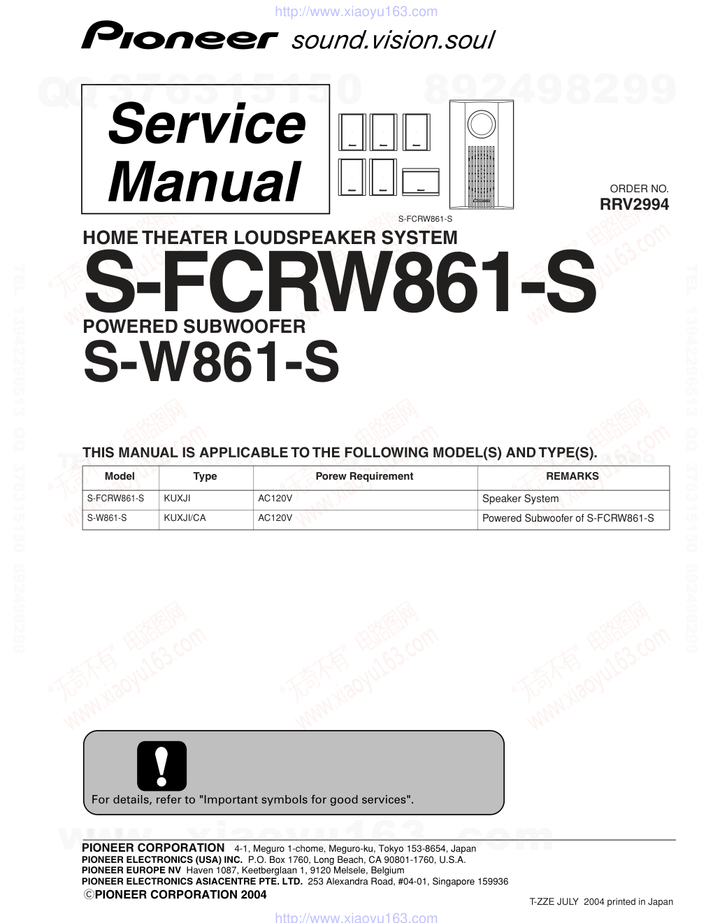
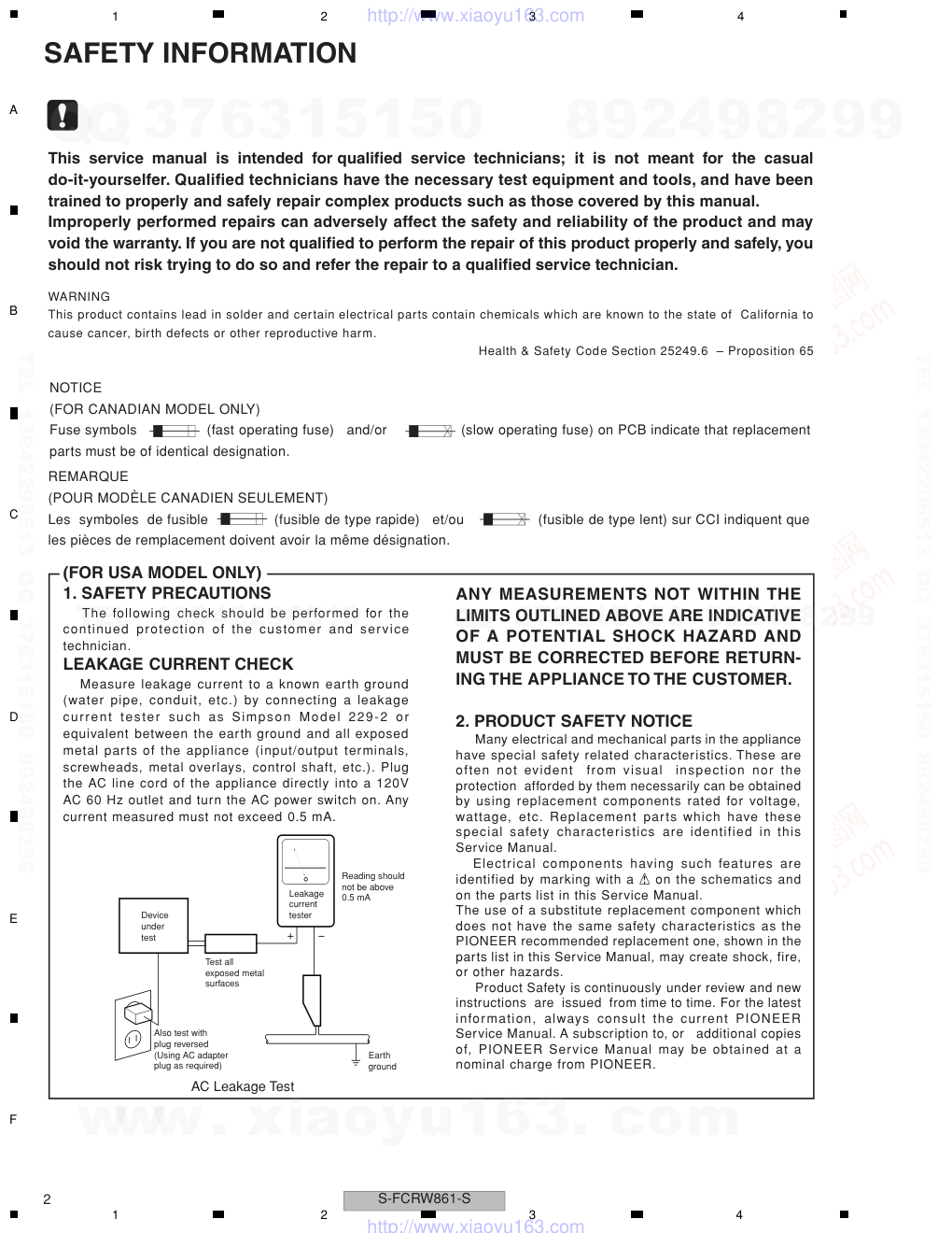
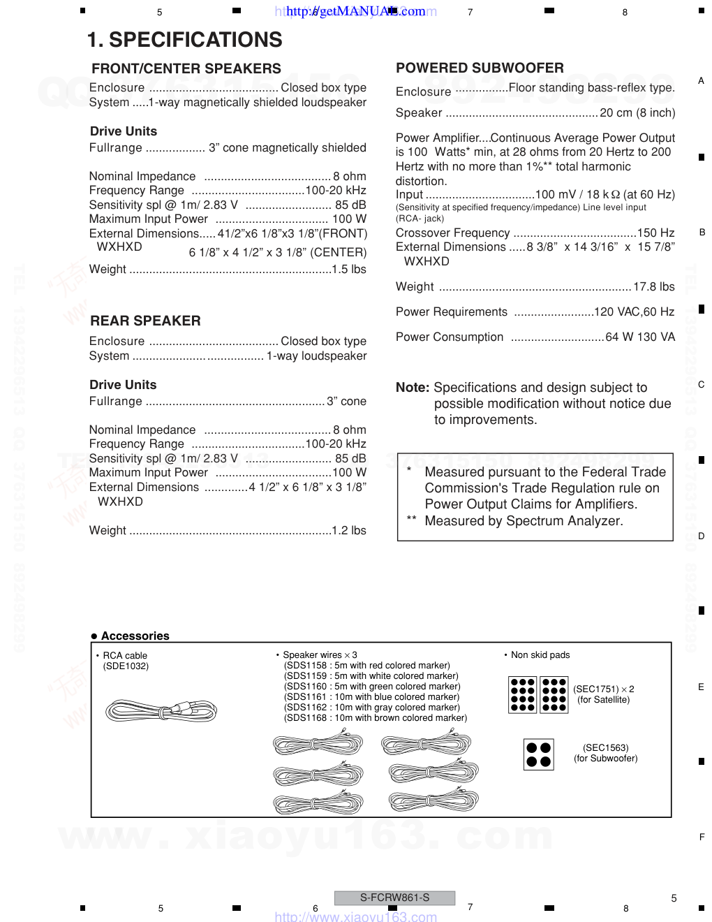
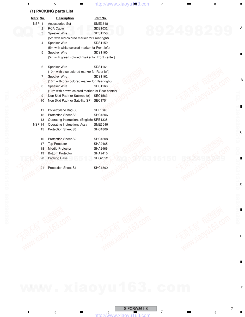
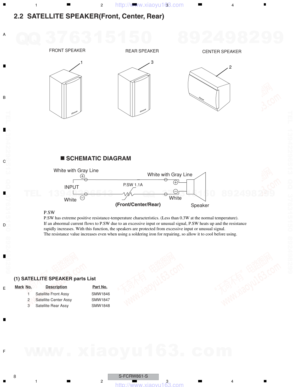
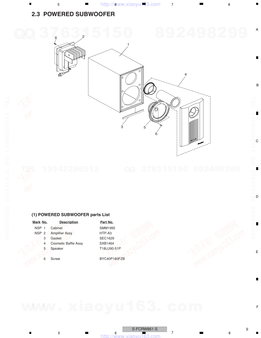
ORDER NO. PIONEER CORPORATION 4-1, Meguro 1-chome, Meguro-ku, Tokyo 153-8654, Japan PIONEER ELECTRONICS (USA) INC. P.O. Box 1760, Long Beach, CA 90801-1760, U.S.A. PIONEER EUROPE NV Haven 1087, Keetberglaan 1, 9120 Melsele, Belgium PIONEER ELECTRONICS ASIACENTRE PTE. LTD. 253 Alexandra Road, #04-01, Singapore 159936 PIONEER CORPORATION 2004 S-FCRW861-S RRV2994 HOME THEATER LOUDSPEAKER SYSTEM S-FCRW861-S POWERED SUBWOOFER S-W861-S THIS MANUAL IS APPLICABLE TO THE FOLLOWING MODEL(S) AND TYPE(S). Model Type Porew Requirement REMARKS S-FCRW861-S KUXJI AC120V Speaker System S-W861-S KUXJI/CA AC120V Powered Subwoofer of S-FCRW861-S For details, refer to "Important symbols for good services". T-ZZE JULY 2004 printed in Japan www. xiaoyu163. com QQ 376315150 9 9 2 8 9 4 2 9 8 TEL 13942296513 9 9 2 8 9 4 2 9 8 0 5 1 5 1 3 6 7 3 Q Q TEL 13942296513 QQ 376315150 892498299 TEL 13942296513 QQ 376315150 892498299 http://www.xiaoyu163.com S-FCRW861-S 2 1 2 3 4 1 2 3 4 C D F A B E SAFETY INFORMATION This service manual is intended for qualified service technicians; it is not meant for the casual do-it-yourselfer. Qualified technicians have the necessary test equipment and tools, and have been trained to properly and safely repair complex products such as those covered by this manual. Improperly performed repairs can adversely affect the safety and reliability of the product and may void the warranty. If you are not qualified to perform the repair of this product properly and safely, you should not risk trying to do so and refer the repair to a qualified service technician. WARNING This product contains lead in solder and certain electrical parts contain chemicals which are known to the state of California to cause cancer, birth defects or other reproductive harm. Health & Safety Code Section 25249.6 – Proposition 65 NOTICE (FOR CANADIAN MODEL ONLY) Fuse symbols (fast operating fuse) and/or (slow operating fuse) on PCB indicate that replacement parts must be of identical designation. REMARQUE (POUR MODÈLE CANADIEN SEULEMENT) Les symboles de fusible (fusible de type rapide) et/ou (fusible de type lent) sur CCI indiquent que les pièces de remplacement doivent avoir la même désignation. ANY MEASUREMENTS NOT WITHIN THE LIMITS OUTLINED ABOVE ARE INDICATIVE OF A POTENTIAL SHOCK HAZARD AND MUST BE CORRECTED BEFORE RETURN- ING THE APPLIANCE TO THE CUSTOMER. 2. PRODUCT SAFETY NOTICE Many electrical and mechanical parts in the appliance have special safety related characteristics. These are often not evident from visual inspection nor the protection afforded by them necessarily can be obtained by using replacement components rated for voltage, wattage, etc. Replacement parts which have these special safety characteristics are identified in this Service Manual. Electrical components having such features are identified by marking with a on the schematics and on the parts list in this Service Manual. The use of a substitute replacement component which does not have the same safety characteristics as the PIONEER recommended replacement one, shown in the parts list in this Service Manual, may create shock, fire, or other hazards. Product Safety is continuously under review and new instructions are issued from time to time. For the latest information, always consult the current PIONEER Service Manual. A subscription to, or additional copies of, PIONEER Service Manual may be obtained at a nominal charge from PIONEER. (FOR USA MODEL ONLY) 1. SAFETY PRECAUTIONS The following check should be performed for the continued protection of the customer and service technician. LEAKAGE CURRENT CHECK Measure leakage current to a known earth ground (water pipe, conduit, etc.) by connecting a leakage current tester such as Simpson Model 229-2 or equivalent between the earth ground and all exposed metal parts of the appliance (input/output terminals, screwheads, metal overlays, control shaft, etc.). Plug the AC line cord of the appliance directly into a 120V AC 60 Hz outlet and turn the AC power switch on. Any current measured must not exceed 0.5 mA. Device under test Leakage current tester Earth ground Reading should not be above 0.5 mA Also test with plug reversed (Using AC adapter plug as required) Test all exposed metal surfaces AC Leakage Test www. xiaoyu163. com QQ 376315150 9 9 2 8 9 4 2 9 8 TEL 13942296513 9 9 2 8 9 4 2 9 8 0 5 1 5 1 3 6 7 3 Q Q TEL 13942296513 QQ 376315150 892498299 TEL 13942296513 QQ 376315150 892498299 http://www.xiaoyu163.com S-FCRW861-S 3 5 6 7 8 5 6 7 8 C D F A B E [ Important symbols for good services ] In this manual, the symbols shown-below indicate that adjustments, settings or cleaning should be made securely. When you find the procedures bearing any of the symbols, be sure to fulfill them: 2. Adjustments To keep the original performances of the product, optimum adjustments or specification confirmation is indispensable. In accordance with the procedures or instructions described in this manual, adjustments should be performed. 3. Cleaning For optical pickups, tape-deck heads, lenses and mirrors used in projection monitors, and other parts requiring cleaning, proper cleaning should be performed to restore their performances. 5. Lubricants, glues, and replacement parts Appropriately applying grease or glue can maintain the product performances. But improper lubrication or applying glue may lead to failures or troubles in the product. By following the instructions in this manual, be sure to apply the prescribed grease or glue to proper portions by the appropriate amount.For replacement parts or tools, the prescribed ones should be used. 4. Shipping mode and shipping screws To protect the product from damages or failures that may be caused during transit, the shipping mode should be set or the shipping screws should be installed before shipping out in accordance with this manual, if necessary. 1. Product safety You should conform to the regulations governing the product (safety, radio and noise, and other regulations), and should keep the safety during servicing by following the safety instructions described in this manual. S-FCRW861-S Speaker System SATELLITE SPEAKER (Front) SMW1846 SATELLITE SPEAKER (Center) SMW1847 SATELLITE SPEAKER (Rear) SMW1848 POWERED SUBWOOFER S-W861-S www. xiaoyu163. com QQ 376315150 9 9 2 8 9 4 2 9 8 TEL 13942296513 9 9 2 8 9 4 2 9 8 0 5 1 5 1 3 6 7 3 Q Q TEL 13942296513 QQ 376315150 892498299 TEL 13942296513 QQ 376315150 892498299 http://www.xiaoyu163.com S-FCRW861-S 4 1 2 3 4 1 2 3 4 C D F A B E CONTENTS SAFETY INFORMATION..................................................................................................................................... 2 1. SPECIFICATIONS ............................................................................................................................................ 5 2. EXPLODED VIEWS AND PARTS LIST ............................................................................................................ 6 2.1 PACKING ................................................................................................................................................... 6 2.2 SATELLITE SPEAKER(Front, Center, Rear) ............................................................................................. 8 2.3 POWERED SUBWOOFER ........................................................................................................................ 9 2.4 POWER AMP SECTION.......................................................................................................................... 10 3. SCHEMATIC DIAGRAM ................................................................................................................................. 12 3.1 OVERALL BLOCK DIAGRAM.................................................................................................................. 12 3.2 AMP and OPERATION ASSYS................................................................................................................ 14 4. PCB CONNECTION DIAGRAM ..................................................................................................................... 16 4.1 AMP and OPERATION ASSYS................................................................................................................ 17 5. PCB PARTS LIST ........................................................................................................................................... 19 6. ADJUSTMENT ............................................................................................................................................... 21 7. GENERAL INFORMATION............................................................................................................................. 22 7.1 DISASSEMBLY ........................................................................................................................................ 22 8. PANEL FACILITIES ........................................................................................................................................ 23 www. xiaoyu163. com QQ 376315150 9 9 2 8 9 4 2 9 8 TEL 13942296513 9 9 2 8 9 4 2 9 8 0 5 1 5 1 3 6 7 3 Q Q TEL 13942296513 QQ 376315150 892498299 TEL 13942296513 QQ 376315150 892498299 http://www.xiaoyu163.com S-FCRW861-S 5 5 6 7 8 5 6 7 8 C D F A B E 1. SPECIFICATIONS FRONT/CENTER SPEAKERS Drive Units Accessories • RCA cable (SDE1032) • Speaker wires × 3 (SDS1158 : 5m with red colored marker) (SDS1159 : 5m with white colored marker) (SDS1160 : 5m with green colored marker) (SDS1161 : 10m with blue colored marker) (SDS1162 : 10m with gray colored marker) (SDS1168 : 10m with brown colored marker) • Non skid pads (SEC1751) × 2 (for Satellite) (SEC1563) (for Subwoofer) Enclosure ....................................... Closed box type System .....1-way magnetically shielded loudspeaker Fullrange .................. 3” cone magnetically shielded Nominal Impedance ...................................... 8 ohm Frequency Range ..................................100-20 kHz Sensitivity spl @ 1m/ 2.83 V .......................... 85 dB Maximum Input Power .................................. 100 W External Dimensions..... 41/2”x6 1/8”x3 1/8”(FRONT) 6 1/8” x 4 1/2” x 3 1/8” (CENTER) WXHXD Weight .............................................................1.5 lbs Enclosure ....................................... Closed box type System ....................................... 1-way loudspeaker Fullrange ......................................................3” cone Nominal Impedance ...................................... 8 ohm Frequency Range ..................................100-20 kHz Sensitivity spl @ 1m/ 2.83 V .......................... 85 dB Maximum Input Power ...................................100 W External Dimensions .............4 1/2” x 6 1/8” x 3 1/8” WXHXD Weight .............................................................1.2 lbs Enclosure ................Floor standing bass-reflex type. Speaker ..............................................20 cm (8 inch) Power Amplifier....Continuous Average Power Output is 100 Watts* min, at 28 ohms from 20 Hertz to 200 Hertz with no more than 1%** total harmonic distortion. Input .................................100 mV / 18 k (at 60 Hz) (Sensitivity at specified frequency/impedance) Line level input (RCA- jack) Crossover Frequency .....................................150 Hz External Dimensions .....8 3/8” x 14 3/16” x 15 7/8” WXHXD Weight ..........................................................17.8 lbs Power Requirements ........................120 VAC,60 Hz Power Consumption ............................64 W 130 VA Note: Specifications and design subject to possible modification without notice due to improvements. * Measured pursuant to the Federal Trade Commission's Trade Regulation rule on Power Output Claims for Amplifiers. ** Measured by Spectrum Analyzer. REAR SPEAKER Drive Units POWERED SUBWOOFER http://getMANUAL.com www. xiaoyu163. com QQ 376315150 9 9 2 8 9 4 2 9 8 TEL 13942296513 9 9 2 8 9 4 2 9 8 0 5 1 5 1 3 6 7 3 Q Q TEL 13942296513 QQ 376315150 892498299 TEL 13942296513 QQ 376315150 892498299 http://www.xiaoyu163.com S-FCRW861-S 6 1 2 3 4 1 2 3 4 C D F A B E 2. EXPLODED VIEWS AND PARTS LIST 2.1 PACKING Parts marked by "NSP" are generally unavailable because they are not in our Master Spare Parts List. The mark found on some component parts indicates the importance of the safety factor of the part. Therefore, when replacing, be sure to use parts of identical designation. Screws adjacent to mark on product are used for disassembly. For the applying amount of lubricants or glue, follow the instructions in this manual. (In the case of no amount instructions, apply as you think it appropriate.) NOTES: 12 16 13 14 12 17 18 21 15 19 20 1 5 4 3 6 7 8 2 9 10 11 10 www. xiaoyu163. com QQ 376315150 9 9 2 8 9 4 2 9 8 TEL 13942296513 9 9 2 8 9 4 2 9 8 0 5 1 5 1 3 6 7 3 Q Q TEL 13942296513 QQ 376315150 892498299 TEL 13942296513 QQ 376315150 892498299 http://www.xiaoyu163.com S-FCRW861-S 7 5 6 7 8 5 6 7 8 C D F A B E (1) PACKING parts List Mark No. Description Part No. NSP 1 Accessories Set SME3548 2 RCA Cable SDE1032 3 Speaker Wire SDS1158 (5m with red colored marker for Front right) 4 Speaker Wire SDS1159 (5m with white colored marker for Front left) 5 Speaker Wire SDS1160 (5m with green colored marker for Front center) 6 Speaker Wire SDS1161 (10m with blue colored marker for Rear left) 7 Speaker Wire SDS1162 (10m with gray colored marker for Rear right) 8 Speaker Wire SDS1168 (10m with brown colored marker for Rear center) 9 Non Skid Pad (for Subwoofer) SEC1563 10 Non Skid Pad (for Satellite SP) SEC1751 11 Polyethylene Bag S0 SHL1343 12 Protection Sheet S3 SHC1806 13 Operating Instructions (English) SRB1335 NSP 14 Operating Instructions Assy SME3549 15 Protection Sheet S6 SHC1809 16 Protection Sheet S2 SHC1808 17 Top Protector SHA2465 18 Middle Protector SHA2466 19 Bottom Protector SHA2410 20 Packing Case SHG2592 21 Protection Sheet S1 SHC1802 www. xiaoyu163. com QQ 376315150 9 9 2 8 9 4 2 9 8 TEL 13942296513 9 9 2 8 9 4 2 9 8 0 5 1 5 1 3 6 7 3 Q Q TEL 13942296513 QQ 376315150 892498299 TEL 13942296513 QQ 376315150 892498299 http://www.xiaoyu163.com S-FCRW861-S 8 1 2 3 4 1 2 3 4 C D F A B E 2.2 SATELLITE SPEAKER(Front, Center, Rear) (1) SATELLITE SPEAKER parts List REAR SPEAKER CENTER SPEAKER FRONT SPEAKER Speaker White with Gray Line White with Gray Line White White P.SW 1.1A INPUT (Front/Center/Rear) SCHEMATIC DIAGRAM 1 3 2 P.SW P.SW has extreme positive resistance-temperature characteristics. (Less than 0.3W at the normal temperature). If an abnormal current flows to P.SW due to an excessive input or unusual signal, P.SW heats up and the resistance rapidly increases. With this function, the speakers are protected from excessive input or unusual signal. The resistance value increases even when using a soldering iron for repairing, so allow it to cool before using. Mark No. Description Part No. 1 Satellite Front Assy SMW1846 2 Satellite Center Assy SMW1847 3 Satellite Rear Assy SMW1848 www. xiaoyu163. com QQ 376315150 9 9 2 8 9 4 2 9 8 TEL 13942296513 9 9 2 8 9 4 2 9 8 0 5 1 5 1 3 6 7 3 Q Q TEL 13942296513 QQ 376315150 892498299 TEL 13942296513 QQ 376315150 892498299 http://www.xiaoyu163.com S-FCRW861-S 9 5 6 7 8 5 6 7 8 C D F A B E 2.3 POWERED SUBWOOFER (1) POWERED SUBWOOFER parts List 6 5 3 2 6 1 4 Mark No. Description Part No. NSP 1 Cabinet SMM1995 NSP 2 Amplifier Assy HTP-A3 3 Gasket SEC1629 4 Cosmetic Baffle Assy SXB1464 5 Speaker T18LU90-51P 6 Screw BYC40P180FZB www. xiaoyu163. com QQ 376315150 9 9 2 8 9 4 2 9 8 TEL 13942296513 9 9 2 8 9 4 2 9 8 0 5 1 5 1 3 6 7 3 Q Q TEL 13942296513 QQ 376315150 892498299 TEL 13942296513 QQ 376315150 892498299 http://www.xiaoyu163.com S-FCRW861-S 10 1 2 3 4 1 2 3 4 C D F A B E 2.4 POWER AMP SECTION A B A 11 17 21 19 6 6 6 6 21 1 21 8 3 7 7 4 10 2 12 9 18 14 VR201 parts 15 16 20 11 13 6 5 22 10 A www. xiaoyu163. com QQ 376315150 9 9 2 8 9 4 2 9 8 TEL 13942296513 9 9 2 8 9 4 2 9 8 0 5 1 5 1 3 6 7 3 Q Q TEL 13942296513 QQ 376315150 892498299 TEL 13942296513 QQ 376315150 892498299 http://www.xiaoyu163.com S-FCRW861-S 11 5 6 7 8 5 6 7 8 C D F A B E POWER AMP SECTION parts List Mark No. Description Part No. 1 AMP ASSY AWU7760 2 OPERATION ASSY AWU7761 > 3 AC Power Cord PDG1064 4 Operation Panel ANC8292 NSP 5 Heat Sink ANH7117 6 Screw ABA1052 7 Screw BPZ30P080FZK 8 Cord Stopper CM-22C 9 Rear Case Assy AXG7085 10 Air Packing L AEB7172 11 Air Packing S AEB7174 12 Rear Case AMC7039 13 Mica Sheet AEE7033 14 Vol Knob Assy PXA1621 NSP 15 Vol Knob PAC1951 NSP 16 Spring PBH1229 > 17 Fuse (FU1) 5A REK1067 18 Fuse Caution Label ARW7083 19 ICP 65 Label ARW7084 20 PBS Holder ANG7329 21 Screw IPZ30P120FMC 22 HS Holder ANG7397 www. xiaoyu163. com QQ 376315150 9 9 2 8 9 4 2 9 8 TEL 13942296513 9 9 2 8 9 4 2 9 8 0 5 1 5 1 3 6 7 3 Q Q TEL 13942296513 QQ 376315150 892498299 TEL 13942296513 QQ 376315150 892498299 http://www.xiaoyu163.com S-FCRW861-S 12 1 2 3 4 1 2 3 4 C D F A B E 3. SCHEMATIC DIAGRAM 3.1 OVERALL BLOCK DIAGRAM Buff Buff Gain Adj Vref +6 V +6 V -6 V Vref Power IND OP Amp MAIN Volume 7 LEVEL DIAGRAM Buff (+6dB) Line Level AC120V 60Hz H. P. F. L. P. F. IN to Photo Coupler D101-D104 S5688G Offset Cancel Photo Coupler to Power AMP Ó Ó + − [dBv] 30 20 10 0 +8dB +6dB +6dB -1.5 -10 -18.5dBv 50Hz : 120mV IC 201 NJM2904M FU1 REK1067(5A) IC 201 NJM2904M IC 41 NJM2904M IC 44 NJM7906FA IC 43 NJM7806FA D31-D34 S5688G +16v +16v D201 T11 T12 D33 D31 D32 D34 PC41 TLP621(Y) JA201 2 5 7 2 1 1 Q201 2SC2412K OPERATON ASSY (AWU7761) B +12.6v -12.6v - 6v + 6v + 6.1v 0 v B A A B C C www. xiaoyu163. com QQ 376315150 9 9 2 8 9 4 2 9 8 TEL 13942296513 9 9 2 8 9 4 2 9 8 0 5 1 5 1 3 6 7 3 Q Q TEL 13942296513 QQ 376315150 892498299 TEL 13942296513 QQ 376315150 892498299 http://www.xiaoyu163.com S-FCRW861-S 13 5 6 7 8 5 6 7 8 C D F A B E AMP ASSY (AWU7760) A Signal feedback Power AMP Over Voltage Detection Speaker Charge balance and DC feedback Buff Clip Det. AC ON/OFF Mute Slow Start FET Thermal Detection Ó Ó + − +34.5dB 34.5dBv ( 53 V ) Total Gain 53dB ( 50Hz) IC 41 NJM2904M Q53, Q54 2SC4060 Q21 IRF640 Q55 DTA124EK D15 G3SBA20L C13, C14 Q56 2SK246 Q58 2SK246 6 7 +84v - 84v 168v D D E E www. xiaoyu163. com QQ 376315150 9 9 2 8 9 4 2 9 8 TEL 13942296513 9 9 2 8 9 4 2 9 8 0 5 1 5 1 3 6 7 3 Q Q TEL 13942296513 QQ 376315150 892498299 TEL 13942296513 QQ 376315150 892498299 http://www.xiaoyu163.com S-FCRW861-S 14 1 2 3 4 1 2 3 4 C D F A B E 3.2 AMP and OPERATION ASSYS B OPERATION ASSY • NOTE FOR FUSE REPLACEMENT FOR CONTINUED PROTECTION AGAINST RISK OF FIRE. REPLACE WITH SAME TYPE AND RATINGS OF FUSE. CAUTION - AC POWER CORD KUC : PDG1064 KUC : 60Hz AC120V POWER TRANSFORMER : AUDIO SIGNAL SIGNAL ROUTE (AWU7761) A B www. xiaoyu163. com QQ 376315150 9 9 2 8 9 4 2 9 8 TEL 13942296513 9 9 2 8 9 4 2 9 8 0 5 1 5 1 3 6 7 3 Q Q TEL 13942296513 QQ 376315150 892498299 TEL 13942296513 QQ 376315150 892498299 http://www.xiaoyu163.com S-FCRW861-S 15 5 6 7 8 5 6 7 8 C D F A B E ADX7356 A AMP ASSY CAUTION : FOR CONTINUED PROTECTION AGAINST RISK OF FIRE. REPLACE ONLY WITH SAME TYPE NO. 491005 FOR IC21, 491003 FOR IC11, IC12 MFD. BY LITTELFUSE INC. POWER TRANSFORMER (AWU7760) A NOTES: When ordering service parts, be sure to refer to EXPLODED VIEWS and PARTS LIST or PCB PARTS LIST . The > mark found on some component parts indicates the importance of the safety factor of the part. Therefore, when replacing, be sure to use parts of identical designation. : The power supply is shown with the marked box. http://getMANUAL.com www. xiaoyu163. com QQ 376315150 9 9 2 8 9 4 2 9 8 TEL 13942296513 9 9 2 8 9 4 2 9 8 0 5 1 5 1 3 6 7 3 Q Q TEL 13942296513 QQ 376315150 892498299 TEL 13942296513 QQ 376315150 892498299 http://www.xiaoyu163.com S-FCRW861-S 16 1 2 3 4 1 2 3 4 C D F A B E 4. PCB CONNECTION DIAGRAM NOTE FOR PCB DIAGRAMS: 1. Part numbers in PCB diagrams match those in the schematic diagrams. 2. A comparison between the main parts of PCB and schematic diagrams is shown below. Symbol in PCB Diagrams Symbol in Schematic Diagrams Part Name Transistor Transistor with resistor Field effect transistor B C E B C E B C E D G S B C E B C E B C E D G S D G S 3. The parts mounted on this PCB include all necessary parts for several destination. For further information for respective destinations, be sure to check with the schematic diagram. 4. Viewpoint of PCB diagrams Resistor array 3-terminal regulator Capacitor Connector P. C. Board Chip Part SIDE B SIDE A www. xiaoyu163. com QQ 376315150 9 9 2 8 9 4 2 9 8 TEL 13942296513 9 9 2 8 9 4 2 9 8 0 5 1 5 1 3 6 7 3 Q Q TEL 13942296513 QQ 376315150 892498299 TEL 13942296513 QQ 376315150 892498299 http://www.xiaoyu163.com S-FCRW861-S 17 5 6 7 8 5 6 7 8 C D F A B E 4.1 AMP and OPERATION ASSYS W122 C11 W112 C224 IC12 W133 CN201 W213 Q11 W132 C32 Q52 W102 W136 W113 D51 W109 C101 W106 W118 W134 D101 D18 C43 Q53 VR41 C53 C14 W107 CN31 W135 C36 C103 C2 D26 C72 IC21 C62 Q12 D1 R63 D21 D32 C19 D28 C74 W111 D15 D34 W126 D24 C45 D33 C51 W121 T12 IC43 W128 C1 W119 D36 W137 PC41 W101 IC44 C91 W124 W108 D17 D52 W138 D31 C42 D53 W120 W139 W117 C21 W103 W115 CN51 W104 D37 Q51 Q56 W127 Q21 Q54 D102 W130 D23 L1 CN2 C31 C44 C73 C20 D16 W114 H2 W129 C39 W116 W105 W131 C57 C33 C54 CN1 C34 IC11 C12 W110 C13 D55 C75 R67 C65 D27 C63 CN3 C22 W140 C59 C71 C61 H1 Q58 D104D103 C35 D22 T11 W123 Q57 W125 D25 6 G RED S D 2 C13 7540 I 3 1 BOND C J11 D D B G AWK -Vcc ATT7058 O SIG GAIN Adj +6V 4 C 2 -Vcc 1 E 6 1 7632 AMP ASSY SECONDARY C12 491005 4 5 LIVE -6V 7555 REF E 7 1 PRODUCTION CODE C11 -6V 4 GND +Vcc BOND AWU 6 9 S BOND Vcc O FR1S P 3 3 G C14 491003 NEUTRAL 2 1 B 7434 S I 8 C E PRIMARY ANP7319-D B 1 REF 1 +6V 2 knife F.B. B ATT7059 S knife BOND Y2 BLACK C REF D E 8 1 +Vcc FU1 491003 CN202 W205 W208 C213 C210 C208 J201 C211 W206 W201 C209 VR201 W202 W210 D204 C202 D202 W204 C212 C227 D201 C201 W209 S201 W203 D203 VR202 JA201 W207 JA202 7435 1 F.B. FC OUTPUT GND GND GND 1 7541 SIG OPERATION SIG FR1S P INPUT Vcc SIG LEVEL VOL GND HIGH GND DC 1 AWU fc SHIFTER GND 1 GND PHASE 0/180 POWER IND OPERATION ASSY B AMP ASSY A AC POWER CORD (ANP7319-D) (ANP7319-D) Q51 IC11IC12 Q53 Q54 Q57 IC21 Q21 Q12 Q11 Q52 Q56 Q58 IC43 IC44 VR41 To Speaker SIDE A SIDE A A B A B www. xiaoyu163. com QQ 376315150 9 9 2 8 9 4 2 9 8 TEL 13942296513 9 9 2 8 9 4 2 9 8 0 5 1 5 1 3 6 7 3 Q Q TEL 13942296513 QQ 376315150 892498299 TEL 13942296513 QQ 376315150 892498299 http://www.xiaoyu163.com S-FCRW861-S 18 1 2 3 4 1 2 3 4 C D F A B E + ~ ~ - +6V SIG E E C D PRIMARY E REF S Vcc E 1 -Vcc D B G B B 1 ANP7319-D F.B. E C -6V E D I O E E +6V C O E E S SECONDARY -6V 1 +Vcc C +Vcc I B G GND REF E -Vcc CN201 S C46 C27 C52 C41 C56 R35 R14 R27 C23 D35 R68 R51 R92 R215 IC41 C76 TH21 R26 R60 C25 R32 D11 R57 C38 R55 R31 R13 R16 Q201 R69 R56 C55 R25 R70 Q23 Q55 R44 R41 R43 R80 Q71 C26 R21 TH22 R224 R59 R72 C102 Q72 C48 R78 IC51 R12 R65 C64 R45 R15 R33 R34 R91 R64 R75 R79 Q22 R36 R73 R52 R42 R23 R19 R62 R217 R58 Q31 C47 R71 R20 C37 R76 R66 R17 R18 R11 R24 R83 R53 R61 R54 R77 R82 R81 R74 R22 1 1 1 Vcc GND GND 1 GND SIG CN202 GND SIG S101 1 HIGH GND SIG F.B. GND GND J201 1 C229 R202 R211 R203 R229 R228 R230 C207 IC201 C214 C218 IC203 R213 C230 R223 R210 R214 R216 C205 R201 C204 R218 R212 R207 C206 C228 C231 IC202 R209 C217 R208 R204 C203 OPERATION ASSY B AMP ASSY A (ANP7319-D) (ANP7319-D) IC203 IC202 IC201 Q71 Q22 Q23 Q72 Q31 Q201 IC51 IC41 Q55 SIDE B SIDE B A B A B www. xiaoyu163. com QQ 376315150 9 9 2 8 9 4 2 9 8 TEL 13942296513 9 9 2 8 9 4 2 9 8 0 5 1 5 1 3 6 7 3 Q Q TEL 13942296513 QQ 376315150 892498299 TEL 13942296513 QQ 376315150 892498299 http://www.xiaoyu163.com S-FCRW861-S 19 5 6 7 8 5 6 7 8 C D F A B E 5. PCB PARTS LIST Parts marked by "NSP" are generally unavailable because they are not in our Master Spare Parts List. The mark found on some component parts indicates the importance of the safety factor of the part. Therefore, when replacing, be sure to use parts of identical designation. When ordering resistors, first convert resistance values into code form as shown in the following examples. Ex.1 When there are 2 effective digits (any digit apart from 0), such as 560 ohm and 47k ohm (tolerance is shown by J=5%, and K=10%). Ex.2 When there are 3 effective digits (such as in high precision metal film resistors). 5 6 1 4 7 3 R 5 0 1 R 0 5 6 2 1 NOTES: 560 Ω 47k Ω 0.5 Ω 1 Ω RD1/4PU J RD1/4PU J RN2H K RS1P K 56 x 10 1 47 x 10 3 R50 1R0 561 473 5.62k Ω RN1/4PC F 562 x 10 1 5621 Mark No. Description Part No. LIST OF ASSEMBLIES NSP 1..SUB WOOFER AMP AWK7722 2..AMP ASSY AWU7760 2..OPERATION ASSY AWU7761 Mark No. Description Part No. AAMP ASSY SEMICONDUCTORS IC41, IC51 NJM2904M > IC43 NJM7806FA > IC44 NJM7906FA > Q52 2SA1009A Q22, Q31 2SA1037K Q11, Q12 2SA1625 > Q51 2SC2333 Q201, Q23 2SC2412K > Q53, Q54 2SC4060 Q56 2SK246 > Q57 2SK246 Q58 2SK246 Q55 DTA124EK > Q21 IRF640 > D52, D55 11EQS06 D23, D53 1SS133 > D26 20E2-FC D35 DAN217 > D15 G3SBA20L D17, D18, D37 MTZJ15A > D21 MTZJ18B D25 MTZJ20A D36 MTZJ6.2B D27 MTZJ6.8B > D101-D104, D16, D24, D28 S5688G > D31-D34, D51 S5688G > TH22 AEX7005 > PC41 TLP621 COILS AND FILTERS > L1 LINE FILTER ATF-151 TRANSFORMERS > T12 ATT7058 > T11 ATT7059 CAPACITORS > C2 (0.033/250) ACE7023 C13, C14 (2200/100) ACH7140 C19, C20 CCCSL470K2H C42-C45 CEAT100M50 C224, C31, C32, C51 CEAT101M16 C101 CEAT101M25 C61 CEAT1R0M50 C33, C34 CEAT221M16 C36 CEAT330M16 C39 CEAT470M16 C63 CEATR10M50 C22 CEHAT1R0M50 C62 CEHAT2R2M50 C21 CEHAT470M50 C53, C54 CKCYB102K2H C23 CKSQYB103K50 C64 CKSQYB223K50 C41 CKSQYB472K50 C25-C27, C46 CKSQYB473K50 RESISTORS R67 RD1/4PU223J > R26 RS1/10S101J > R57, R58 RS1/10S221J VR41 (4.7K) VCP1154 Other Resistors RS1/10S###J OTHERS CN201 4P CONNECTOR 52147-0410 J11 CABLE ASSY 2P ADX7356 > IC11, IC12 PROTECTOR(3A) AEK7015 > IC21 PROTECTOR(5A) AEK7019 H1, H2 FUSE CLIPE AKR7001 > TERMINAL RKC-061 PCB BINDER VEF1040 SPACER AEC7391 BOPERATION ASSY SEMICONDUCTORS IC201, IC203 NJM2904M D201 AEL7014 D202 MTZJ6.2B CAPACITORS C214 CCSQCH330J50 C201 CEAT100M50 Mark No. Description Part No. www. xiaoyu163. com QQ 376315150 9 9 2 8 9 4 2 9 8 TEL 13942296513 9 9 2 8 9 4 2 9 8 0 5 1 5 1 3 6 7 3 Q Q TEL 13942296513 QQ 376315150 892498299 TEL 13942296513 QQ 376315150 892498299 http://www.xiaoyu163.com S-FCRW861-S 20 1 2 3 4 1 2 3 4 C D F A B E C211-C213 CEAT101M16 C209 CFTLA154J50 C228 CKSQYB473K50 C205 CKSQYB682K50 C210, C227 CQMBA473J50 RESISTORS VR201 (50K) ACS7033 Other Resistors RS1/10S###J OTHERS 4P CABLE HOLDER 51048-0400 J201 JUMPER WIRE D20PYY0425E JA201 1P JACK VKB1077 Mark No. Description Part No. www. xiaoyu163. com QQ 376315150 9 9 2 8 9 4 2 9 8 TEL 13942296513 9 9 2 8 9 4 2 9 8 0 5 1 5 1 3 6 7 3 Q Q TEL 13942296513 QQ 376315150 892498299 TEL 13942296513 QQ 376315150 892498299 http://www.xiaoyu163.com S-FCRW861-S 21 5 6 7 8 5 6 7 8 C D F A B E 6. ADJUSTMENT Test Point VR41 Gain Adj Digital Voltmeter AMP ASSY + - A SIDE A 28Ω 3 W Adjustment VR ATTENTION ¶ Don’ t make speaker terminal short circuit during the power supply injection. ¶ Since the PRIMARY part of the AMP ASSY is not insulated, be careful of electric shock. ¶ Be sure to disconnect the power supply cord before touching the AMP ASSY board. ¶ Discharge the C13, C14 capacitors! 6.1 MEASURING INSTRUMENTS ¶ Provide yourself with the following measuring devices: (1) Digital voltmeter (2) Oscilloscope (3) Attenuator (4) Low-frequency oscillator 77777 GAIN Adjustment (1) Decrease the level of the Adjustment Variable resistors (VR) for the channel to adjusted. (2) Increase LEVEL VOLUME maximum. (3) Adjust GAIN (VR41) volume. ¶ Apply the signal to the Line IN of JA201. ¶ As the gain from IN to SPEAKER OUT 53dB(freq. = 50 Hz), input of 10mVrms to Input results in output of 0.72 W (4.5Vrms/28 W) at SPEAKER OUT . ¶ After power-supply ON, after waiting abut 10 seconds, it adjustment because, wave form rises behind time for slow start operation. www. xiaoyu163. com QQ 376315150 9 9 2 8 9 4 2 9 8 TEL 13942296513 9 9 2 8 9 4 2 9 8 0 5 1 5 1 3 6 7 3 Q Q TEL 13942296513 QQ 376315150 892498299 TEL 13942296513 QQ 376315150 892498299 http://www.xiaoyu163.com S-FCRW861-S 22 1 2 3 4 1 2 3 4 C D F A B E 7. GENERAL INFORMATION 7.1 DISASSEMBLY 1. SUBWOOFER ¶ POWER Removing the AMP SECTION AMP SECTION Remove the 8 screws 1 from the power amplifier. Remove the 6 screws 2 from the power amplifier. Loosen the power lead. . Remove the connector lead, etc. ¶ FRONT PANEL The front panel is attached to the cabinet by its bosses applied with adhesive. To detach it, pry it open by inserting a flat blade screwdriver into bottom slot between the cabinet and front panel. ¶ SPEAKER To detach first remove the front panel, then remove the 4 external screws. 2. SATELLITE ¶ Satellite Speakers are provided as assembly units. Removing the Operation Panel Screw1 Screw2 AMP ASSY A OPERATION ASSY B Operation Panel www. xiaoyu163. com QQ 376315150 9 9 2 8 9 4 2 9 8 TEL 13942296513 9 9 2 8 9 4 2 9 8 0 5 1 5 1 3 6 7 3 Q Q TEL 13942296513 QQ 376315150 892498299 TEL 13942296513 QQ 376315150 892498299 http://www.xiaoyu163.com S-FCRW861-S 23 5 6 7 8 5 6 7 8 C D F A B E 8. PANEL FACILITIES SUBWOOFER REAR SECTION If the output of the receiver connected to this unit is high or if the output has a low range boosted by the Bass control, Bass boost, or other means, there may be some sound distortion even if the level of the unit is lowered. In this case, lower the output level (Volume, Bass control, Bass boost) on the receiver side. POWER INDICATOR Illuminates RED when the power is being supplied. VOLUME LEVEL Volume of subwoofer is adjusted with this knob. Turn this knob clockwise to raise the level. • Starting with “MIN“, turn this knob and raise the volume slowly. If the unit is turned on with the volume set too high, it could cause hearing and/or speaker damage. Do not turn the volume up excessively high. The low frequency sound is apt to be raised too high since it is less disturbing and harder to detect than high frequencies. Caution must be taken here since the amplifier and speaker will be clipped when the output of the amplifier or receiver is increased with the subwoofer level set to “MAX“. LINE LEVEL IN Connect SUBWOOFER OUTPUT terminal of the receiver to this terminal with the supplied RCA cable. 1 2 3 VOLUME LEVEL LINE LEVEL IN POWER INDICATOR 1 3 2 MIN MAX www. xiaoyu163. com QQ 376315150 9 9 2 8 9 4 2 9 8 TEL 13942296513 9 9 2 8 9 4 2 9 8 0 5 1 5 1 3 6 7 3 Q Q TEL 13942296513 QQ 376315150 892498299 TEL 13942296513 QQ 376315150 892498299 http://www.xiaoyu163.com
版权声明
1. 本站所有素材,仅限学习交流,仅展示部分内容,如需查看完整内容,请下载原文件。
2. 会员在本站下载的所有素材,只拥有使用权,著作权归原作者所有。
3. 所有素材,未经合法授权,请勿用于商业用途,会员不得以任何形式发布、传播、复制、转售该素材,否则一律封号处理。
4. 如果素材损害你的权益请联系客服QQ:77594475 处理。