先锋PIONEER S-W100S电路图
 "先锋PIONEER S-W100S电路图-0")
 "先锋PIONEER S-W100S电路图-1")
 "先锋PIONEER S-W100S电路图-2")
 "先锋PIONEER S-W100S电路图-3")
 "先锋PIONEER S-W100S电路图-4")
 "先锋PIONEER S-W100S电路图-5")
 "先锋PIONEER S-W100S电路图-6")
 "先锋PIONEER S-W100S电路图-7")
 "先锋PIONEER S-W100S电路图-8")
 "先锋PIONEER S-W100S电路图-9")
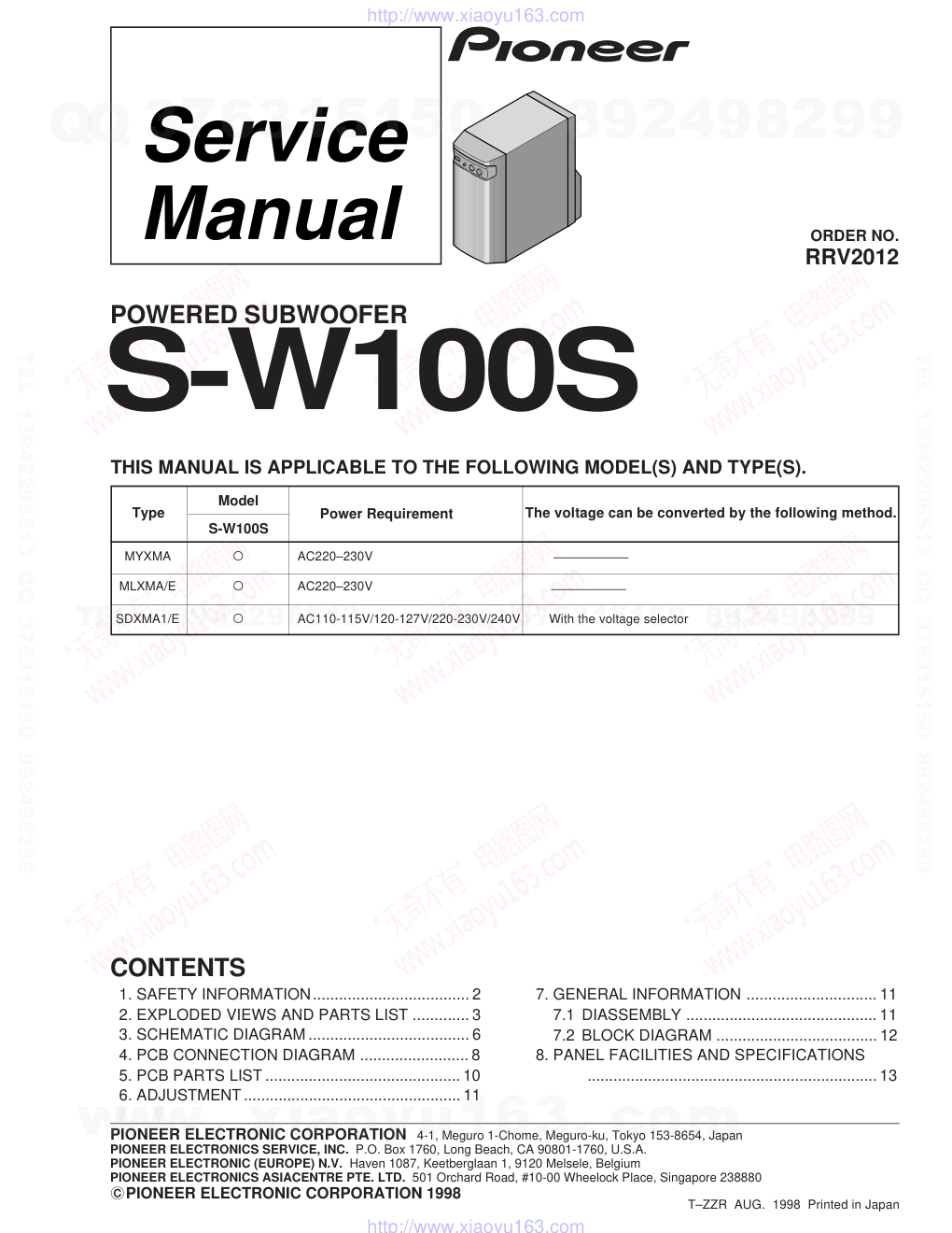
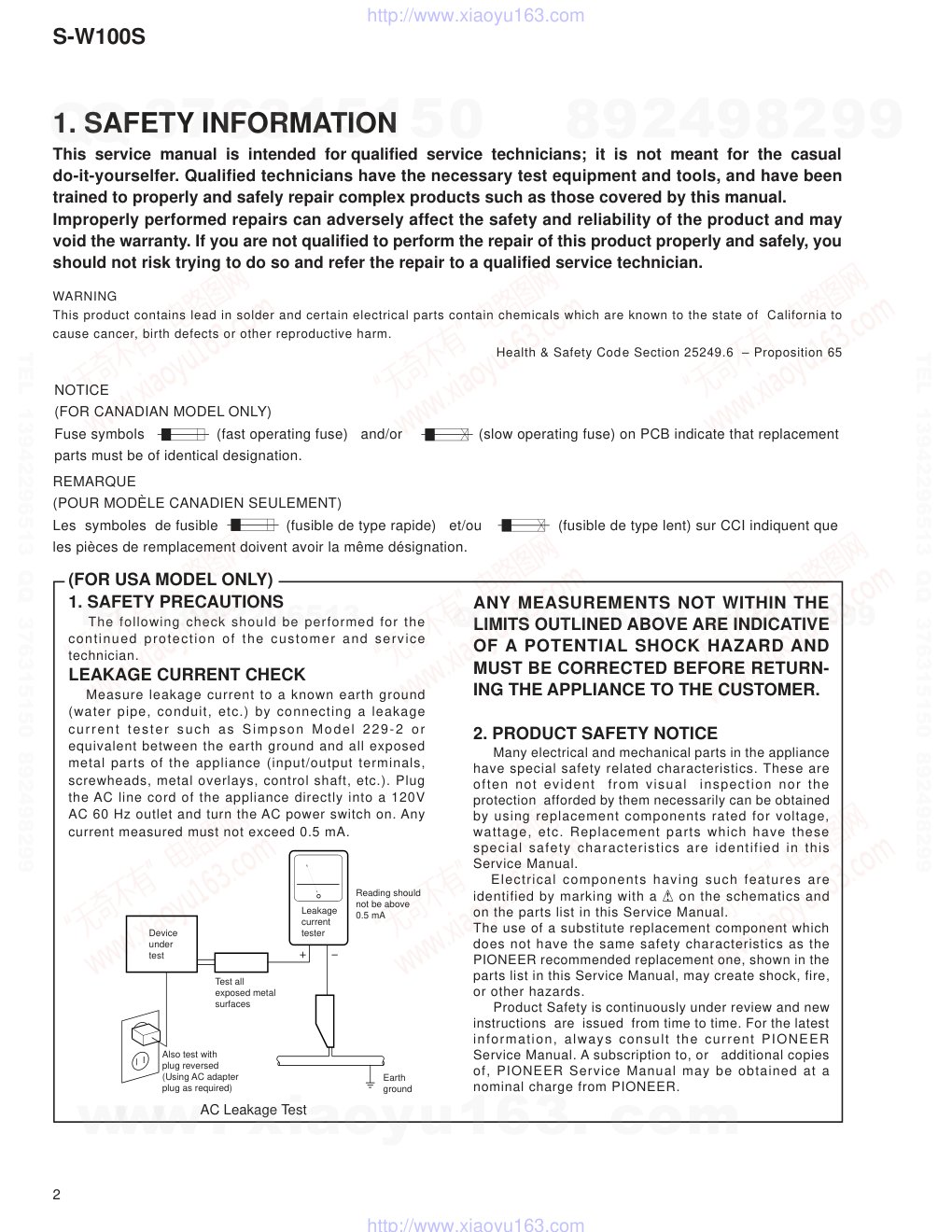
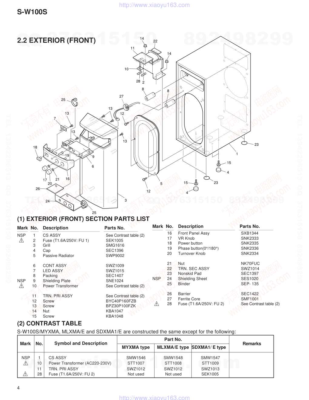
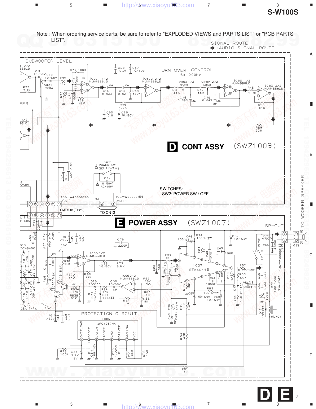
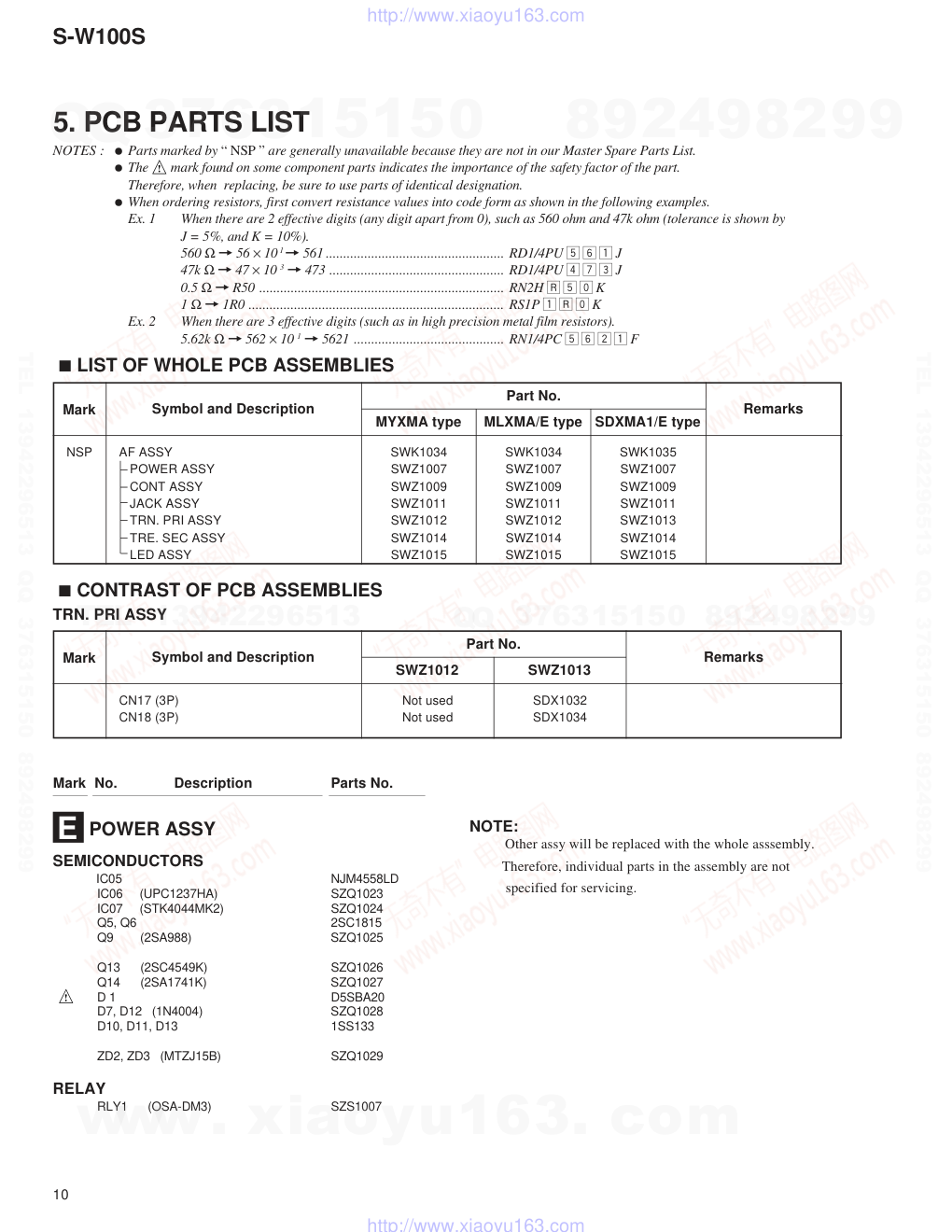
ORDER NO. PIONEER ELECTRONIC CORPORATION 4-1, Meguro 1-Chome, Meguro-ku, Tokyo 153-8654, Japan PIONEER ELECTRONICS SERVICE, INC. P.O. Box 1760, Long Beach, CA 90801-1760, U.S.A. PIONEER ELECTRONIC (EUROPE) N.V. Haven 1087, Keetberglaan 1, 9120 Melsele, Belgium PIONEER ELECTRONICS ASIACENTRE PTE. LTD. 501 Orchard Road, #10-00 Wheelock Place, Singapore 238880 � � � � � � � � � �PIONEER ELECTRONIC CORPORATION 1998 MYXMA ‡ AC220–230V POWERED SUBWOOFER RRV2012 T–ZZR AUG. 1998 Printed in Japan S-W100S CONTENTS 1. SAFETY INFORMATION.................................... 2 2. EXPLODED VIEWS AND PARTS LIST ............. 3 3. SCHEMATIC DIAGRAM ..................................... 6 4. PCB CONNECTION DIAGRAM ......................... 8 5. PCB PARTS LIST ............................................. 10 6. ADJUSTMENT.................................................. 11 7. GENERAL INFORMATION .............................. 11 7.1 DIASSEMBLY ............................................ 11 7.2 BLOCK DIAGRAM ..................................... 12 8. PANEL FACILITIES AND SPECIFICATIONS ................................................................... 13 THIS MANUAL IS APPLICABLE TO THE FOLLOWING MODEL(S) AND TYPE(S). Type Power Requirement Model S-W100S MLXMA/E ‡ AC220–230V SDXMA1/E ‡ AC110-115V/120-127V/220-230V/240V With the voltage selector The voltage can be converted by the following method. www. xiaoyu163. com QQ 376315150 9 9 2 8 9 4 2 9 8 TEL 13942296513 9 9 2 8 9 4 2 9 8 0 5 1 5 1 3 6 7 3 Q Q TEL 13942296513 QQ 376315150 892498299 TEL 13942296513 QQ 376315150 892498299 http://www.xiaoyu163.com S-W100S 2 1. SAFETY INFORMATION This service manual is intended for qualified service technicians; it is not meant for the casual do-it-yourselfer. Qualified technicians have the necessary test equipment and tools, and have been trained to properly and safely repair complex products such as those covered by this manual. Improperly performed repairs can adversely affect the safety and reliability of the product and may void the warranty. If you are not qualified to perform the repair of this product properly and safely, you should not risk trying to do so and refer the repair to a qualified service technician. WARNING This product contains lead in solder and certain electrical parts contain chemicals which are known to the state of California to cause cancer, birth defects or other reproductive harm. Health & Safety Code Section 25249.6 – Proposition 65 NOTICE (FOR CANADIAN MODEL ONLY) Fuse symbols (fast operating fuse) and/or (slow operating fuse) on PCB indicate that replacement parts must be of identical designation. REMARQUE (POUR MODÈLE CANADIEN SEULEMENT) Les symboles de fusible (fusible de type rapide) et/ou (fusible de type lent) sur CCI indiquent que les pièces de remplacement doivent avoir la même désignation. ANY MEASUREMENTS NOT WITHIN THE LIMITS OUTLINED ABOVE ARE INDICATIVE OF A POTENTIAL SHOCK HAZARD AND MUST BE CORRECTED BEFORE RETURN- ING THE APPLIANCE TO THE CUSTOMER. 2. PRODUCT SAFETY NOTICE Many electrical and mechanical parts in the appliance have special safety related characteristics. These are often not evident from visual inspection nor the protection afforded by them necessarily can be obtained by using replacement components rated for voltage, wattage, etc. Replacement parts which have these special safety characteristics are identified in this Service Manual. Electrical components having such features are identified by marking with a on the schematics and on the parts list in this Service Manual. The use of a substitute replacement component which does not have the same safety characteristics as the PIONEER recommended replacement one, shown in the parts list in this Service Manual, may create shock, fire, or other hazards. Product Safety is continuously under review and new instructions are issued from time to time. For the latest information, always consult the current PIONEER Service Manual. A subscription to, or additional copies of, PIONEER Service Manual may be obtained at a nominal charge from PIONEER. (FOR USA MODEL ONLY) 1. SAFETY PRECAUTIONS The following check should be performed for the continued protection of the customer and service technician. LEAKAGE CURRENT CHECK Measure leakage current to a known earth ground (water pipe, conduit, etc.) by connecting a leakage current tester such as Simpson Model 229-2 or equivalent between the earth ground and all exposed metal parts of the appliance (input/output terminals, screwheads, metal overlays, control shaft, etc.). Plug the AC line cord of the appliance directly into a 120V AC 60 Hz outlet and turn the AC power switch on. Any current measured must not exceed 0.5 mA. Device under test Leakage current tester Earth ground Reading should not be above 0.5 mA Also test with plug reversed (Using AC adapter plug as required) Test all exposed metal surfaces AC Leakage Test www. xiaoyu163. com QQ 376315150 9 9 2 8 9 4 2 9 8 TEL 13942296513 9 9 2 8 9 4 2 9 8 0 5 1 5 1 3 6 7 3 Q Q TEL 13942296513 QQ 376315150 892498299 TEL 13942296513 QQ 376315150 892498299 http://www.xiaoyu163.com S-W100S 3 2. EXPLODED VIEWS AND PARTS LIST 2.1 PACKING (1) PACKING PARTS LIST Mark No. Description Parts No. NOTES : ÷ Parts marked by “ NSP ” are generally unavailable because they are not in our Master Spare Parts List. ÷ The mark found on some component parts indicates the importance of the safety factor of the part. Therefore, when replacing, be sure to use parts of identical designation. ÷ Screw adjacent to ∞ mark on the product are used for disassembly. 1 8 4 9 6 2 7 10 4 3 5 9 1 Packing Case See Contrast table (2) 2 Top Protector SHA2126 NSP 3 Warranty Card See Contrast table (2) 4 Sheet (550X300X0.5) SHC1721 NSP 5 Cord Set SME2789 6 Operating instructions See Contrast table (2) 7 Speaker cords (L=3.0m) SDS1052 8 Bottom Protector SHA2127 NSP 9 Polyethylene Bag E11- 024 10 RCA Plug cord (L=3.0m) SDE1028 Part No. Remarks Mark MYXMA type MLXMA/E type SDXMA1/ E type (2) CONTRAST TABLE S-W100S/MYXMA, MLXMA/E and SDXMA1/E are constructed the same except for the following: 1 Packing Case SHG2108 SHG2110 SHG2109 NSP 3 Warranty Card ARY7022 Not used Not used 6 Operating instructions SRD1200 Not used Not used (English/ French/ German/ ltalian/ Dutch/ Swedish/ Spanish/ Portuguese) 6 Operating instructions Not used SRD1202 Not used (English/ Chinese) 6 Operating instructions Not used Not used SRD1201 (English/ Chinese/Spanish/ Portuguese) No. Symbol and Description www. xiaoyu163. com QQ 376315150 9 9 2 8 9 4 2 9 8 TEL 13942296513 9 9 2 8 9 4 2 9 8 0 5 1 5 1 3 6 7 3 Q Q TEL 13942296513 QQ 376315150 892498299 TEL 13942296513 QQ 376315150 892498299 http://www.xiaoyu163.com S-W100S 4 NSP 1 CS ASSY SMW1546 SMW1548 SMW1547 10 Power Transformer (AC220-230V) STT1007 STT1008 STT1009 11 TRN. PRI ASSY SWZ1012 SWZ1012 SWZ1013 28 Fuse (T1.6A/250V: FU 2) Not used Not used SEK1005 (1) EXTERIOR (FRONT) SECTION PARTS LIST Mark No. Description Parts No. Mark No. Description Parts No. NSP 1 CS ASSY See Contrast table (2) 2 Fuse (T1.6A/250V: FU 1) SEK1005 3 Grill SMG1616 4 Cap SEC1396 5 Passive Radiator SWP9002 6 CONT ASSY SWZ1009 7 LED ASSY SWZ1015 8 Packing SEC1407 NSP 9 Shielding Plate SNE1024 10 Power Transformer See Contrast table (2) 11 TRN. PRI ASSY See Contrast table (2) 12 Screw BYC40P160FZB 13 Screw BPZ30P100FZK 14 Nut KBA1047 15 Screw KBA1048 16 Front Panel Assy SXB1344 17 VR Knob SNK2333 18 Power button SNK2335 19 Phase button(0°/180°) SNK2336 20 Turnover Knob SNK2334 21 Nut NK70FUC 22 TRN. SEC ASSY SWZ1014 23 Nonskid Pad SEC1397 NSP 24 Shielding Sheet SES1020 25 Binder SEP- 135 26 Barrier SEC1422 27 Ferrite Core SMF1001 28 Fuse (T1.6A/250V: FU 2) See Contrast table (2) 11 14 14 22 10 8 8 2 28 13 13 13 13 7 18 26 24 19 17 20 21 16 12 12 6 9 5 3 25 15 15 4 4 23 23 1 25 27 2.2 EXTERIOR (FRONT) Part No. Remarks Mark MYXMA type MLXMA/E type SDXMA1/ E type (2) CONTRAST TABLE S-W100S/MYXMA, MLXMA/E and SDXMA1/E are constructed the same except for the following: No. Symbol and Description www. xiaoyu163. com QQ 376315150 9 9 2 8 9 4 2 9 8 TEL 13942296513 9 9 2 8 9 4 2 9 8 0 5 1 5 1 3 6 7 3 Q Q TEL 13942296513 QQ 376315150 892498299 TEL 13942296513 QQ 376315150 892498299 http://www.xiaoyu163.com S-W100S 5 1 AC Power Coed SDG1009 SDG1009 SDG1010 16 Rear Panel Assy SXB1346 SXB1346 SXB1345 26 Fuse (T1.6A/250V: FU 3) SEK1005 SEK1005 Not used 26 Fuse (T5.0A/250V: FU 3) Not used Not used SEK1008 27 Voltage Selector Not used Not used AKX-507 2.3 EXTERIOR (REAR) (1) EXTERIOR (REAR) SECTION PARTS LIST Mark No. Description Parts No. Mark No. Description Parts No. 13 Screw BPZ30P100FZK 14 Screw KBA1049 15 Heatsink SNH1041 16 Rear Panel Assy See Contrast table (2) 17 Packing SEC1407 18 Packing SEC1394 19 Packing SEC1408 20 Packing SEC1393 21 Screw BYC35P200FZB 22 Packing SEC1417 23 Packing SEC1418 24 Packing SEC1419 25 Sheet SEE1069 26 Fuse ( FU 3 ) See Contrast table (2) 27 Voltage Selector See Contrast table (2) 28 Screw BYC40P160FZB 1 AC Power Coed See Contrast table (2) 2 JACK ASSY SWZ1011 3 Rear Cover SNK2332 4 Speaker SWA9003 5 Screw BYC35P250FZB 6 POWER ASSY SWZ1007 7 Screw BBZ30P060FMC 8 Screw BBZ35P080FMC 9 Cord Stopper SNK2361 10 Packing SEC1395 11 Heatsink BRKT (A) SNB1061 12 Heatsink BRKT (B) SNB1062 1 27 9 28 26 28 5 21 21 13 13 16 23 24 2 3 4 28 28 14 8 8 7 7 6 12 11 22 10 15 18 25 17 19 20 Part No. Remarks Mark MYXMA type MLXMA/E type SDXMA1/E type (2) CONTRAST TABLE S-W100S/MYXMA, MLXMA/E and SDXMA1/E are constructed the same except for the following: No. Symbol and Description www. xiaoyu163. com QQ 376315150 9 9 2 8 9 4 2 9 8 TEL 13942296513 9 9 2 8 9 4 2 9 8 0 5 1 5 1 3 6 7 3 Q Q TEL 13942296513 QQ 376315150 892498299 TEL 13942296513 QQ 376315150 892498299 http://www.xiaoyu163.com S-W100S 6 A B C D 1 2 3 4 1 2 3 4 3. SCHEMATIC DIAGRAM A B C F 3.1 JACK , CONT, POWER, LED, TRN. SEC and TRN. PRI ASSEMBLIES LED ASSY (SWZ1015) TRN.SEC ASSY (SWZ1014) TRN. PRI ASSY (SWZ1012 :MY,ML) LD2 POWER TO CN11 B A C F D TRN. PRI ASSY (SWZ1013:SDXMA1/E) TO CN11 C D TO CN14 A 192-W45159992 SMF1001(F1:1/2) BRO ORA GRE YEL BLU 120 – 127V 110 – 115V 220 –230V 240V JK4 : AKX-507A VOLTAGE SELECTOR RED /SDXMA1/E :STT1009 /MYXMA : STT1007 /MLXMA/E : STT1008 SDG1009 : /MYXMA, MLXMA/E SDG1010 : /SDXMA1/E FU3: SEK1008 / SDXMA1/E T5A/250V SEK1005/MYXMA T1.6A/250V /MLXMA/E JACK ASSY www. xiaoyu163. com QQ 376315150 9 9 2 8 9 4 2 9 8 TEL 13942296513 9 9 2 8 9 4 2 9 8 0 5 1 5 1 3 6 7 3 Q Q TEL 13942296513 QQ 376315150 892498299 TEL 13942296513 QQ 376315150 892498299 http://www.xiaoyu163.com S-W100S 7 A B C D 5 6 7 8 5 6 7 8E D TO CN12 D E SMF1001(F1:2/2) SWITCHES: SW2: POWER SW / OFF CONT ASSY POWER ASSY Note : When ordering service parts, be sure to refer to "EXPLODED VIEWS and PARTS LIST" or "PCB PARTS LIST". www. xiaoyu163. com QQ 376315150 9 9 2 8 9 4 2 9 8 TEL 13942296513 9 9 2 8 9 4 2 9 8 0 5 1 5 1 3 6 7 3 Q Q TEL 13942296513 QQ 376315150 892498299 TEL 13942296513 QQ 376315150 892498299 http://www.xiaoyu163.com S-W100S 8 A B C D 1 2 3 4 1 2 3 4 4. PCB CONNECTION DIAGRAM B A D PRIMARY PRIMARY RISK OF FIRE -REPLACE FUSE AS MARKED. JACK ASSY SWZ1011-A CONT ASSY SWZ1009-A CN13 FU3 L101 C81 CN14 R23 R22 J 1 R19 R21 R20 C43 C6 R25 C5 R24 R26 JK1 GND L/P STGND CN6 1 J2 JK2 LED ASSY SWZ-1015-A GND CN9 1 LD2 LDB+ + + + + + + GND L/P STGND 1 1 1 1 1 1 1 1 -GND LDB+ STGD LDB+ GND +15V -15V SIG CN2 CN10 R17 R16 C52 C7 R28 R27 R31 R53 C8 D2 D3 R29 C62 J5 R33 IC1 IC2 IC3 J13 J9 J3 G1 G2 C10 C13 J6 C9 R36 C12 J7 C14 R34 R32 C63 R39 R30 C53 D4 D5 C80 CN5 C38 R41 R40 J11 R59 R43 R35 R37 C11 R38 C37 C28 J10 R42 C16 VR1 VR2 TURN OVER VOLUME CN17 C15 R55 C47 C54 PHASE SW4 J4 CN11 PW SW - PW SW + SW2 POWER SW LED ASSY B CONT ASSY D JACK ASSY A (SNP1078-A) AC POWER CORD IC3 IC2 IC1 VR2 VR1 NOTE FOR PCB DIAGRAMS: 1. Part numbers in PCB diagrams match those in the schematic diagrams. 2. A comparison between the main parts of PCB and schematic diagrams is shown below. Symbol in PCB Diagrams Symbol in Schematic Diagrams Part Name Transistor Transistor with resistor Field effect transistor B C E B C E B C E D G S B C E B C E B C E D G S D G S 3. The parts mounted on this PCB include all necessary parts for several destination. For further information for respective destinations, be sure to check with the schematic diagram. 4. Viewpoint of PCB diagrams Resistor array 3-terminal regulator Capacitor Connector P. C. Board Chip Part SIDE B SIDE A SIDE A www. xiaoyu163. com QQ 376315150 9 9 2 8 9 4 2 9 8 TEL 13942296513 9 9 2 8 9 4 2 9 8 0 5 1 5 1 3 6 7 3 Q Q TEL 13942296513 QQ 376315150 892498299 TEL 13942296513 QQ 376315150 892498299 http://www.xiaoyu163.com S-W100S 9 A B C D 1 2 3 4 1 2 3 4F E C + + + + + + + + + + + + + + + + + STGD LDB+ GND +15V -15V SIG 1 C76 C67 C45 C32 C69 C68 C33 C30 C31 C40 C58 C41 C48 C56 C55 C44 C25 C59 C65 C64 R71 Q6 Q9 Q5 R70 R69 R64 D11 D10 D12 D13 R65 R78 R74 R44 J26 J23 J38 C19 J27 J30 J28 C22 C23 R49 R47 DZ3 R45 C21 J32 C77 J39 C66 CN1 R46 R48 DZ2 C28 R52 D7 AC 0V AC R82 R83 R66 R60 R77 R67 R62 R63 R61 R80 R68 R85 R81 R88 R89 R54 R73 RLY1 PD1 SPK+ SPK- R87 R51 R72 R75 R58 R50 R84 IC 5 1 C70 C61 C60 C39 C57 D1 CN7 C49 C42 C18 CN19 C46 C35 C36 C26 C29 J22 J16 J17 J18 J34 C34 J35 J36 J49 J37 R57 + 1 R56 Q13 C50 C51 J29 J31 Q14 J44 J19 J20 J33 J25 1 1 1 R79 5 10 15 IC 7 IC 6 POWER ASSY SWZ1007-A PRIMARY RISK OF FIRE -REPLACE FUSE AS MARKED. TRN.PRI ASSY SWZ1012-A SWZ1013-A CN12 AC CORD CN4 1 1 1 FU2 FU1 FU2 0V PW SW+ PW SW - 115V 120V 0V 5V AC1 C27 CN3A TH0V 0V 115V 120V 0V 5V P7 P6 P5 P4 P3 P2 J15 J14 P1 CN3 SWZ-1014-A TRN. SEC ASSY P14 P10 P12 AC 0V AC CN8 PD3 PD2 TRN. SEC ASSY F TRN. PRI ASSY C POWER ASSY E (SNP1078-A) SPEAKER POWER TRANSFORMER Q9 IC7 IC6 Q6 Q5 IC5 Q14 Q13 SIDE A www. xiaoyu163. com QQ 376315150 9 9 2 8 9 4 2 9 8 TEL 13942296513 9 9 2 8 9 4 2 9 8 0 5 1 5 1 3 6 7 3 Q Q TEL 13942296513 QQ 376315150 892498299 TEL 13942296513 QQ 376315150 892498299 http://www.xiaoyu163.com S-W100S 10 NSP AF ASSY SWK1034 SWK1034 SWK1035 POWER ASSY SWZ1007 SWZ1007 SWZ1007 CONT ASSY SWZ1009 SWZ1009 SWZ1009 JACK ASSY SWZ1011 SWZ1011 SWZ1011 TRN. PRI ASSY SWZ1012 SWZ1012 SWZ1013 TRE. SEC ASSY SWZ1014 SWZ1014 SWZ1014 LED ASSY SWZ1015 SWZ1015 SWZ1015 5. PCB PARTS LIST Mark No. Description Parts No. NOTES : ÷ Parts marked by “ NSP ” are generally unavailable because they are not in our Master Spare Parts List. ÷ The mark found on some component parts indicates the importance of the safety factor of the part. Therefore, when replacing, be sure to use parts of identical designation. ÷ When ordering resistors, first convert resistance values into code form as shown in the following examples. Ex. 1 When there are 2 effective digits (any digit apart from 0), such as 560 ohm and 47k ohm (tolerance is shown by J = 5%, and K = 10%). 560 Ω = 56 × 10 1 = 561 ................................................... RD1/4PU 5 6 1 J 47k Ω = 47 × 10 3 = 473 .................................................. RD1/4PU 4 7 3 J 0.5 Ω = R50 ...................................................................... RN2H  5 0 K 1 Ω = 1R0 ......................................................................... RS1P 1  0 K Ex. 2 When there are 3 effective digits (such as in high precision metal film resistors). 5.62k Ω = 562 × 10 1 = 5621 ........................................... RN1/4PC 5 6 2 1 F SEMICONDUCTORS IC05 NJM4558LD IC06 (UPC1237HA) SZQ1023 IC07 (STK4044MK2) SZQ1024 Q5, Q6 2SC1815 Q9 (2SA988) SZQ1025 Q13 (2SC4549K) SZQ1026 Q14 (2SA1741K) SZQ1027 D 1 D5SBA20 D7, D12 (1N4004) SZQ1028 D10, D11, D13 1SS133 ZD2, ZD3 (MTZJ15B) SZQ1029 RELAY RLY1 (OSA-DM3) SZS1007 POWER ASSY E Mark Symbol and Description Part No. MYXMA type MLXMA/E type SDXMA1/E type Remarks 7 LIST OF WHOLE PCB ASSEMBLIES 7 CONTRAST OF PCB ASSEMBLIES CN17 (3P) Not used SDX1032 CN18 (3P) Not used SDX1034 Mark Remarks Symbol and Description Part No. SWZ1012 SWZ1013 TRN. PRI ASSY NOTE: Other assy will be replaced with the whole asssembly. Therefore, individual parts in the assembly are not specified for servicing. www. xiaoyu163. com QQ 376315150 9 9 2 8 9 4 2 9 8 TEL 13942296513 9 9 2 8 9 4 2 9 8 0 5 1 5 1 3 6 7 3 Q Q TEL 13942296513 QQ 376315150 892498299 TEL 13942296513 QQ 376315150 892498299 http://www.xiaoyu163.com S-W100S 11 7. GENERAL INFORMATION 7.1 DISASSEMBLY Grill ASSY Slit Speaker Rear Cover POWER Assy JACK Assy Back board 2 1 2 3 3 A 4 5 5 6 1 6. ADJUSTMENT There is no information to be shown in this chapter. ¶ REAR COVER SECTION Remove 6 screws (1) from the Rear Cover. ¶ JACK ASSY SECTION Remove 6 screws (2) from the JACK Assy. Remove the A connector from the CONT Assy . ¶ SPEAKER SECTION Remove the Rear Cover. Each speaker is attached to the Back board by 4 external screws (3). detach it, unfasten those screws. When attaching it, face its terminal upward. ¶ POWER ASSY SECTION Remove the Rear Cover. Remove 6 screws (5) from the Back board. Remove the 6 connector from the POWER Assy . ¶ GRILL ASSY SECTION Remove the Grill Assy. Insert a screwdriver into the slit under the Grill Assy to pry open the front grill gradually and uniformly. Remove 3 (AC and Signal) connectors from the CONT ASSY . www. xiaoyu163. com QQ 376315150 9 9 2 8 9 4 2 9 8 TEL 13942296513 9 9 2 8 9 4 2 9 8 0 5 1 5 1 3 6 7 3 Q Q TEL 13942296513 QQ 376315150 892498299 TEL 13942296513 QQ 376315150 892498299 http://www.xiaoyu163.com S-W100S 12 7.2 BLOCK DIAGRAM BUFFER INPUT AMP IC01 NJM4558L PHASE SW FLAT AMP NJM4558L IC02 LOW CUT FILTER NJM4558L IC03 VOLUME HIGH CUT FILTER NJM4558L IC03 NJM4558L IC05 LIMITER STK4044∏ IC07 POWER AMP UPC1237HA IC06 PROTECTION CONTROL + + + + L L R R SPEAKER LEVEL OUTPUT LEVEL INPUT SPEAKER LOW LEVEL IN PUT LOW LEVEL OUT PUT FLAT AMP NJM4558L IC02 FLAT AMP IC05 NJM4558L (0 /180 ) (30 Hz) (50-200Hz) www. xiaoyu163. com QQ 376315150 9 9 2 8 9 4 2 9 8 TEL 13942296513 9 9 2 8 9 4 2 9 8 0 5 1 5 1 3 6 7 3 Q Q TEL 13942296513 QQ 376315150 892498299 TEL 13942296513 QQ 376315150 892498299 http://www.xiaoyu163.com S-W100S 13 8. PANEL FACILITIES AND SPECIFICATIONS 7 PANEL FACILITIES POWERED SUBWOOFER ∫¿ˆ¥YY∫� 1 2 3 4 5 R R L L 67 8 9 FRONT PANEL 1 Power switch (POWER) When pressed, power is turned ON; when pressed again, power is turned OFF. 2 Power Indicator Illuminates when the power is on. 3 Phase switch (PHASE — 0˚ / _ 180˚) When depressed (_ 180˚), the output phase becomes the reverse of the input signal, and when raised (— 0˚ ), it is in the same phase as the input signal. ÷ Normally, the switch is set to (— 0˚ ). But when the sound connection between the subwoofer and the left and right speakers sounds unnatural, try switching to 180˚ and set the switch in the position where the sound is natural. 4 Level knob (LEVEL) Sets the subwoofer volume. ÷ Turn the knob slowly from the MIN position. ÷ With this unit, the bass level can be independently set, so do not turn up the bass on the stereo amplifier. 5 Turnover knob (TURNOVER) Sets the high limit of the frequency played back by the subwoofer. ÷ Setting Criteria 50Hz ... when the diameter of the left/right speakers is 20-cm (8 in.) or more. 100Hz . when the diameter of the left/right speakers is 10 – 25-cm (4 – 10 in.). 200Hz . when the diameter of the left/right speakers is 12-cm (5 in.) or less. 7 SPECIFICATIONS REAR PANEL 6 Line Level Input terminal (LINE LEVEL INPUT) Connects to the stereo amplifier’s SUBWOOFER PRE-OUT terminal, with the specially provided RCA plug cord. 7 Line Level Output terminal (LINE LEVEL OUTPUT) Used for connecting other equipment through the amplifier. 8 Speaker Level Output terminals (SPEAKER LEVEL OUTPUT) When the speakers output terminals on the stereo amplifier are connected to this unit’s SPEAKER LEVEL INPUT terminals 9 and used as the unit’s input signal, these terminals are used to connect the left and right speakers via the unit. 9 Speaker Level Input terminals (SPEAKER LEVEL INPUT) Connect to the speakers output terminals on the stereo amplifier, with the specially provided speaker cords. Cabinet ...................... Floor type with passive radiator system Speaker (Magnetically shielded type) ........... 16 cm cone type Passive radiator .................................. 15.6 cm x 28.6 cm oval Power Amplifier Continous Power Output (RMS) ...... 100 W/4 Ω (30 – 200 Hz) Total Harmonic Distortion ................................................0.5 % (30 – 200 Hz, 4 Ω, 25 W) ÷ Above specifications are for when power supply is 230 V. Input (sensitivity at 100 Hz/impedance) (MYXMA, MLXMA/E) SPEAKER LEVEL .................................... 1.6 V + 1.6 V/15 kΩ (both channels in-phase) LINE LEVEL (RCA jack)...................................... 160 mV/50 kΩ Turnover Frequency .......... 50 – 200 Hz (continuously variable) Outline Dimension .................190 (W) x 430 (H) x 430 (D) mm Weight (without package) ............................................ 10.0 kg Power Requirements European model .............................. AC 220 – 230 V, 50/60 Hz Singapore model.............................. AC 220 – 230 V, 50/60 Hz Multi-voltage model ..............AC 110 – 115V/120V – 127V/220 – 230V /240V (seleccionable), 50/60 Hz Power Consumption Singapore model...............................................................82 W European models..............................................................86 W Multi-voltage model .........................................................243 W Accessories ............................................. Speaker cords x 2 RCA plug cord x 1 Operating instructions x 1 Warranty card (MYXMA: Only) x 1 NOTE: Specifications and design subject to possible modification without notice, due to improvements. www. xiaoyu163. com QQ 376315150 9 9 2 8 9 4 2 9 8 TEL 13942296513 9 9 2 8 9 4 2 9 8 0 5 1 5 1 3 6 7 3 Q Q TEL 13942296513 QQ 376315150 892498299 TEL 13942296513 QQ 376315150 892498299 http://www.xiaoyu163.com
版权声明
1. 本站所有素材,仅限学习交流,仅展示部分内容,如需查看完整内容,请下载原文件。
2. 会员在本站下载的所有素材,只拥有使用权,著作权归原作者所有。
3. 所有素材,未经合法授权,请勿用于商业用途,会员不得以任何形式发布、传播、复制、转售该素材,否则一律封号处理。
4. 如果素材损害你的权益请联系客服QQ:77594475 处理。