先锋PIONEER S-IC691AXTWWL5电路图
 "先锋PIONEER S-IC691AXTWWL5电路图-0")
 "先锋PIONEER S-IC691AXTWWL5电路图-1")
 "先锋PIONEER S-IC691AXTWWL5电路图-2")
 "先锋PIONEER S-IC691AXTWWL5电路图-3")
 "先锋PIONEER S-IC691AXTWWL5电路图-4")
 "先锋PIONEER S-IC691AXTWWL5电路图-5")
 "先锋PIONEER S-IC691AXTWWL5电路图-6")
 "先锋PIONEER S-IC691AXTWWL5电路图-7")
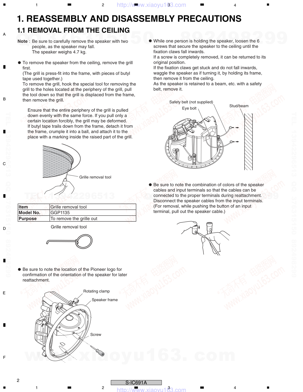
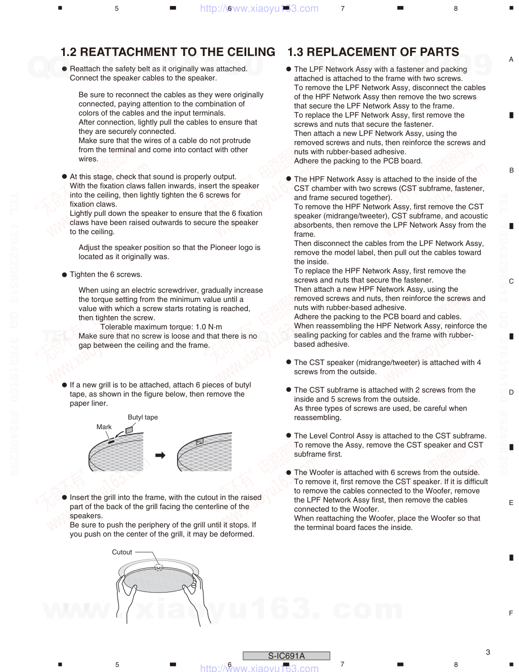
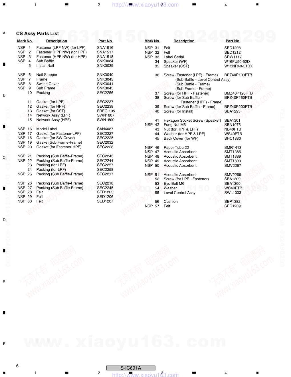
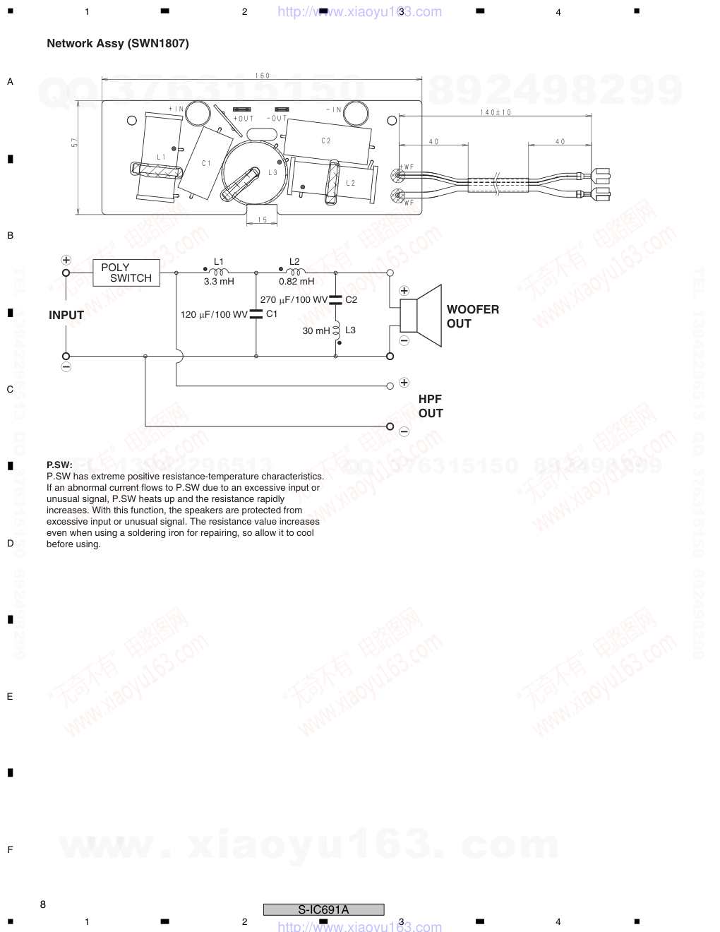
ORDER NO. PIONEER CORPORATION 1-1, Shin-ogura, Saiwai-ku, Kawasaki-shi, Kanagawa 212-0031, Japan PIONEER ELECTRONICS (USA) INC. P.O. Box 1760, Long Beach, CA 90801-1760, U.S.A. PIONEER EUROPE NV Haven 1087, Keetberglaan 1, 9120 Melsele, Belgium PIONEER ELECTRONICS ASIACENTRE PTE. LTD. 253 Alexandra Road, #04-01, Singapore 159936 PIONEER CORPORATION 2010 S-IC691A RRV4040 T-ZZZ FEB. 2010 Printerd in Japan IN-CEILING SPEAKER S-IC691A /XTWWL5 This service manual is intended for qualified service technicians; it is not meant for the casual do-it-yourselfer. Qualified technicians have the necessary test equipment and tools, and have been trained to properly and safely repair complex products such as those covered by this manual. Improperly performed repairs can adversely affect the safety and reliability of the product and may void the warranty. If you are not qualified to perform the repair of this product properly and safely, you should not risk trying to do so and refer the repair to a qualified service technician. WARNING This product contains certain electrical parts contain chemicals which are known to the State of California to cause cancer, birth defects or other reproductive harm. Health & Safety Code Section 25249.6 - Proposition 65 www. xiaoyu163. com QQ 376315150 9 9 2 8 9 4 2 9 8 TEL 13942296513 9 9 2 8 9 4 2 9 8 0 5 1 5 1 3 6 7 3 Q Q TEL 13942296513 QQ 376315150 892498299 TEL 13942296513 QQ 376315150 892498299 http://www.xiaoyu163.com 2 S-IC691A 1 2 3 4 C D F A B E 1 2 3 4 1. REASSEMBLY AND DISASSEMBLY PRECAUTIONS To remove the speaker from the ceiling, remove the grill first. (The grill is press-fit into the frame, with pieces of butyl tape used together.) To remove the grill, hook the special tool for removing the grill to the holes located at the periphery of the grill, pull the tool down so that the grill is displaced from the frame, then remove the grill. While one person is holding the speaker, loosen the 6 screws that secure the speaker to the ceiling until the fixation claws fall inwards. If a screw is completely removed, it can be returned to its original position. If the fixation claws get stuck and do not fall inwards, waggle the speaker as if turning it, by holding its frame, then remove it from the ceiling. As the speaker is retained to a beam, etc. with a safety belt, remove it. Be sure to note the combination of colors of the speaker cables and input terminals so that the cables can be connected to the proper terminals during reattachment. Disconnect the speaker cables from the input terminals. (For removal, while pushing the button of an input terminal, pull out the speaker cable.) Be sure to note the location of the Pioneer logo for confirmation of the orientation of the speaker for later reattachment. Ensure that the entire periphery of the grill is pulled down evenly with the same force. If you pull only a certain location forcibly, the grill may be deformed. If butyl tape trails down from the frame, detach it from the frame, crumple it into a ball, and attach it to the place with a marking inside the raised part of the grill. Note : Be sure to carefully remove the speaker with two people, as the speaker may fall. The speaker weighs 4.7 kg. Item Grille removal tool Model No. GGP1135 Purpose To remove the grille out Safety belt (not supplied) Eye bolt Grille removal tool Grille removal tool Rotating clamp Speaker frame Screw Stud/beam 1.1 REMOVAL FROM THE CEILING www. xiaoyu163. com QQ 376315150 9 9 2 8 9 4 2 9 8 TEL 13942296513 9 9 2 8 9 4 2 9 8 0 5 1 5 1 3 6 7 3 Q Q TEL 13942296513 QQ 376315150 892498299 TEL 13942296513 QQ 376315150 892498299 http://www.xiaoyu163.com 3 S-IC691A 5 7 6 8 5 6 7 8 C D F A B E Reattach the safety belt as it originally was attached. Connect the speaker cables to the speaker. At this stage, check that sound is properly output. With the fixation claws fallen inwards, insert the speaker into the ceiling, then lightly tighten the 6 screws for fixation claws. Lightly pull down the speaker to ensure that the 6 fixation claws have been raised outwards to secure the speaker to the ceiling. Tighten the 6 screws. If a new grill is to be attached, attach 6 pieces of butyl tape, as shown in the figure below, then remove the paper liner. Insert the grill into the frame, with the cutout in the raised part of the back of the grill facing the centerline of the speakers. Be sure to push the periphery of the grill until it stops. If you push on the center of the grill, it may be deformed. The LPF Network Assy with a fastener and packing attached is attached to the frame with two screws. To remove the LPF Network Assy, disconnect the cables of the HPF Network Assy then remove the two screws that secure the LPF Network Assy to the frame. To replace the LPF Network Assy, first remove the screws and nuts that secure the fastener. Then attach a new LPF Network Assy, using the removed screws and nuts, then reinforce the screws and nuts with rubber-based adhesive. Adhere the packing to the PCB board. The HPF Network Assy is attached to the inside of the CST chamber with two screws (CST subframe, fastener, and frame secured together). To remove the HPF Network Assy, first remove the CST speaker (midrange/tweeter), CST subframe, and acoustic absorbents, then remove the LPF Network Assy from the frame. Then disconnect the cables from the LPF Network Assy, remove the model label, then pull out the cables toward the inside. To replace the HPF Network Assy, first remove the screws and nuts that secure the fastener. Then attach a new HPF Network Assy, using the removed screws and nuts, then reinforce the screws and nuts with rubber-based adhesive. Adhere the packing to the PCB board and cables. When reassembling the HPF Network Assy, reinforce the sealing packing for cables and the frame with rubber- based adhesive. The CST speaker (midrange/tweeter) is attached with 4 screws from the outside. The CST subframe is attached with 2 screws from the inside and 5 screws from the outside. As three types of screws are used, be careful when reassembling. The Level Control Assy is attached to the CST subframe. To remove the Assy, remove the CST speaker and CST subframe first. The Woofer is attached with 6 screws from the outside. To remove it, first remove the CST speaker. If it is difficult to remove the cables connected to the Woofer, remove the LPF Network Assy first, then remove the cables connected to the Woofer. When reattaching the Woofer, place the Woofer so that the terminal board faces the inside. Be sure to reconnect the cables as they were originally connected, paying attention to the combination of colors of the cables and the input terminals. After connection, lightly pull the cables to ensure that they are securely connected. Make sure that the wires of a cable do not protrude from the terminal and come into contact with other wires. Adjust the speaker position so that the Pioneer logo is located as it originally was. When using an electric screwdriver, gradually increase the torque setting from the minimum value until a value with which a screw starts rotating is reached, then tighten the screw. Tolerable maximum torque: 1.0 N·m Make sure that no screw is loose and that there is no gap between the ceiling and the frame. Butyl tape Mark Cutout 1.2 REATTACHMENT TO THE CEILING 1.3 REPLACEMENT OF PARTS www. xiaoyu163. com QQ 376315150 9 9 2 8 9 4 2 9 8 TEL 13942296513 9 9 2 8 9 4 2 9 8 0 5 1 5 1 3 6 7 3 Q Q TEL 13942296513 QQ 376315150 892498299 TEL 13942296513 QQ 376315150 892498299 http://www.xiaoyu163.com 4 S-IC691A 1 2 3 4 C D F A B E 1 2 3 4 2. EXPLODED VIEWS AND PARTS LIST Parts marked by "NSP" are generally unavailable because they are not in our Master Spare Parts List. The mark found on some component parts indicates the importance of the safety factor of the part. Therefore, when replacing, be sure to use parts of identical designation. NOTES: 2.1 PACKING 1 Carton Spacer SHB1190 NSP 2 1..Accessories Set SME3936 2-1 2..Polyethylene Bag S2 SHL1295 2-2 2..Operating Instruction SRD1403 (En/Frca/Ja) 3 Grille Assy SMG1914 4 Polyethylene Bag S4 (for Grille) SHL1452 5 Top Protector SHA2627 NSP 6 1..Accessories Set SME3898 (for Butyl Tape) 6-1 2..Butyl Tape SEH1134 6-2 2..Polyethylene Bag SHL1246 NSP 7 1..Accessories Set SME3858 (for Grille Removal Tool) 7-1 2..Polyethylene Bag SHL1246 7-2 2..Grille Removal Tool GGP1135 8 Install Template SRK1038 9 Protection Sheet SHB1201 10 Paint Mask SHC1874 NSP 11 Speaker System • • • • • 12 Bottom Protector SHA2623 13 Polyethylene Bag Sx SHL1481 14 Packing Case SHG2862 NSP 15 Label Serial SRW1112 NSP 16 Caution Card SRN1018 PACKING Parts List Mark No. Description Part No. www. xiaoyu163. com QQ 376315150 9 9 2 8 9 4 2 9 8 TEL 13942296513 9 9 2 8 9 4 2 9 8 0 5 1 5 1 3 6 7 3 Q Q TEL 13942296513 QQ 376315150 892498299 TEL 13942296513 QQ 376315150 892498299 http://www.xiaoyu163.com 5 S-IC691A 5 6 7 8 5 6 7 8 C D F A B E 2.2 CS ASSY 1600WB Rubber-based adhesive 1600WB Rubber-based adhesive www. xiaoyu163. com QQ 376315150 9 9 2 8 9 4 2 9 8 TEL 13942296513 9 9 2 8 9 4 2 9 8 0 5 1 5 1 3 6 7 3 Q Q TEL 13942296513 QQ 376315150 892498299 TEL 13942296513 QQ 376315150 892498299 http://www.xiaoyu163.com 6 S-IC691A 1 2 3 4 C D F A B E 1 2 3 4 NSP 1 Fastener (LPF NW) (for LPF) SNA1516 NSP 2 Fastener (HPF NW) (for HPF) SNA1517 NSP 3 Fastener (HPF NW) (for HPF) SNA1518 NSP 4 Sub Baffl e SNK3084 5 Install Nail SNK3039 NSP 6 Nail Stopper SNK3040 NSP 7 Frame SNK3043 NSP 8 Switch Cover SNK3041 NSP 9 Sub Frame SNK3045 10 Packing SEC2256 11 Gasket (for LPF) SEC2237 12 Gasket (for HPF) SEC2238 13 Gasket (for CST) FREC-105 14 Network Assy (LPF) SWN1807 15 Network Assy (HPF) SWN1800 NSP 16 Model Label SAN4087 NSP 17 Gasket (for Fastener-LPF) SEC2227 NSP 18 Gasket (for SW Cover) SEC2225 NSP 19 Gasket(Sub Frame-Frame) SEC2032 NSP 20 Gasket (for Fastener-HPF) SEC2228 NSP 21 Packing (Sub Baffl e-Frame) SEC2243 NSP 22 Packing (Sub Baffl e-Frame) SEC2244 23 Packing (for LPF) SEC2257 24 Packing (for LPF) SEC2258 NSP 25 Packing (Sub Baffl e-Frame) SEC2217 NSP 26 Packing (Sub Baffl e-Frame) SEC2218 NSP 27 Packing (Sub Baffl e-Frame) SEC2245 NSP 28 Felt SED1205 NSP 29 Felt SED1206 NSP 30 Felt SED1207 NSP 31 Felt SED1208 NSP 32 Felt SED1212 NSP 33 Label Serial SRW1117 34 Speaker (WF) W16FU90-52D 35 Speaker (CST) W13NR40-51DX 36 Screw (Fastener (LPF) - Frame) BPZ40P100FTB (Sub Baffl e - Level Control Assy) (Sub Baffl e - Frame) (Sub Frame - Frame) 37 Screw (for HPF - Fastener) BMZ40P120FTB 38 Screw (for Sub Baffl e - BPZ40P160FTB Fastener (HPF) - Frame) 39 Screw (for Sub Baffl e - Frame) BPZ40P200FTB 40 Screw (for Install) SBA1293 41 Hexagon Socket Screw (Speaker) SBA1301 NSP 42 Fung Nut M6 SBN1075 43 Nut (for HPF & LPF) NB40FTB 44 Washer (for HPF & LPF) WS40FTB 45 Back Cover (for WF) SHC1880 NSP 46 Paper Tube 22 SMR1413 NSP 47 Acoustic Absorbent SMT1385 NSP 48 Acoustic Absorbent SMT1389 NSP 49 Acoustic Absorbent SMT1390 NSP 50 Acoustic Absorbent SMV2267 NSP 51 Acoustic Absorbent SMV2269 52 Screw (for LPF - Fastener) SBA1309 53 Eye Bolt M6 SBA1300 54 Washer WC40FTB 55 Level Control Assy SWL1003 56 Cushion SEP1382 NSP 57 Felt SED1209 CS Assy Parts List Mark No. Description Part No. Mark No. Description Part No. www. xiaoyu163. com QQ 376315150 9 9 2 8 9 4 2 9 8 TEL 13942296513 9 9 2 8 9 4 2 9 8 0 5 1 5 1 3 6 7 3 Q Q TEL 13942296513 QQ 376315150 892498299 TEL 13942296513 QQ 376315150 892498299 http://www.xiaoyu163.com 7 S-IC691A 5 6 7 8 5 6 7 8 C D F A B E Network Assy (SWN1800) R1 L2 C5 C1 C2 C4 C3 C7 L4 L3 L1 C6 Mid OUT Tw OUT P.SW: P.SW has extreme positive resistance-temperature characteristics. If an abnormal current flows to P.SW due to an excessive input or unusual signal, P.SW heats up and the resistance rapidly increases. With this function, the speakers are protected from excessive input or unusual signal. The resistance value increases even when using a soldering iron for repairing, so allow it to cool before using. INPUT 0.56 F/250 V/150 V 27 F/100 VW 68 F/100 VW 27 F/100 VW 2.7 F/250 V/150 V 0.56 F/250 V/150 V 8.2 F/250 V/150 V 0.022 mH 0.62 mH 0.4 mH 0.68 mH 1.0 3. SCHEMATIC DIAGRAM www. xiaoyu163. com QQ 376315150 9 9 2 8 9 4 2 9 8 TEL 13942296513 9 9 2 8 9 4 2 9 8 0 5 1 5 1 3 6 7 3 Q Q TEL 13942296513 QQ 376315150 892498299 TEL 13942296513 QQ 376315150 892498299 http://www.xiaoyu163.com 8 S-IC691A 1 2 3 4 C D F A B E 1 2 3 4 POLY SWITCH 120 F/100 WV 270 F/100 WV INPUT Network Assy (SWN1807) 3.3 mH 0.82 mH 30 mH WOOFER OUT C1 C2 L1 L2 L3 P.SW: P.SW has extreme positive resistance-temperature characteristics. If an abnormal current flows to P.SW due to an excessive input or unusual signal, P.SW heats up and the resistance rapidly increases. With this function, the speakers are protected from excessive input or unusual signal. The resistance value increases even when using a soldering iron for repairing, so allow it to cool before using. HPF OUT www. xiaoyu163. com QQ 376315150 9 9 2 8 9 4 2 9 8 TEL 13942296513 9 9 2 8 9 4 2 9 8 0 5 1 5 1 3 6 7 3 Q Q TEL 13942296513 QQ 376315150 892498299 TEL 13942296513 QQ 376315150 892498299 http://www.xiaoyu163.com
版权声明
1. 本站所有素材,仅限学习交流,仅展示部分内容,如需查看完整内容,请下载原文件。
2. 会员在本站下载的所有素材,只拥有使用权,著作权归原作者所有。
3. 所有素材,未经合法授权,请勿用于商业用途,会员不得以任何形式发布、传播、复制、转售该素材,否则一律封号处理。
4. 如果素材损害你的权益请联系客服QQ:77594475 处理。