先锋PIONEER S-2EX音响电路图
 "先锋PIONEER S-2EX音响电路图-0")
 "先锋PIONEER S-2EX音响电路图-1")
 "先锋PIONEER S-2EX音响电路图-2")
 "先锋PIONEER S-2EX音响电路图-3")
 "先锋PIONEER S-2EX音响电路图-4")
 "先锋PIONEER S-2EX音响电路图-5")
 "先锋PIONEER S-2EX音响电路图-6")
 "先锋PIONEER S-2EX音响电路图-7")
 "先锋PIONEER S-2EX音响电路图-8")
 "先锋PIONEER S-2EX音响电路图-9")
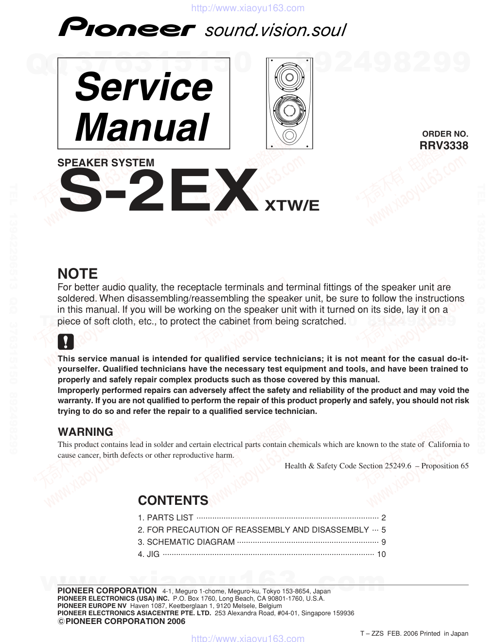
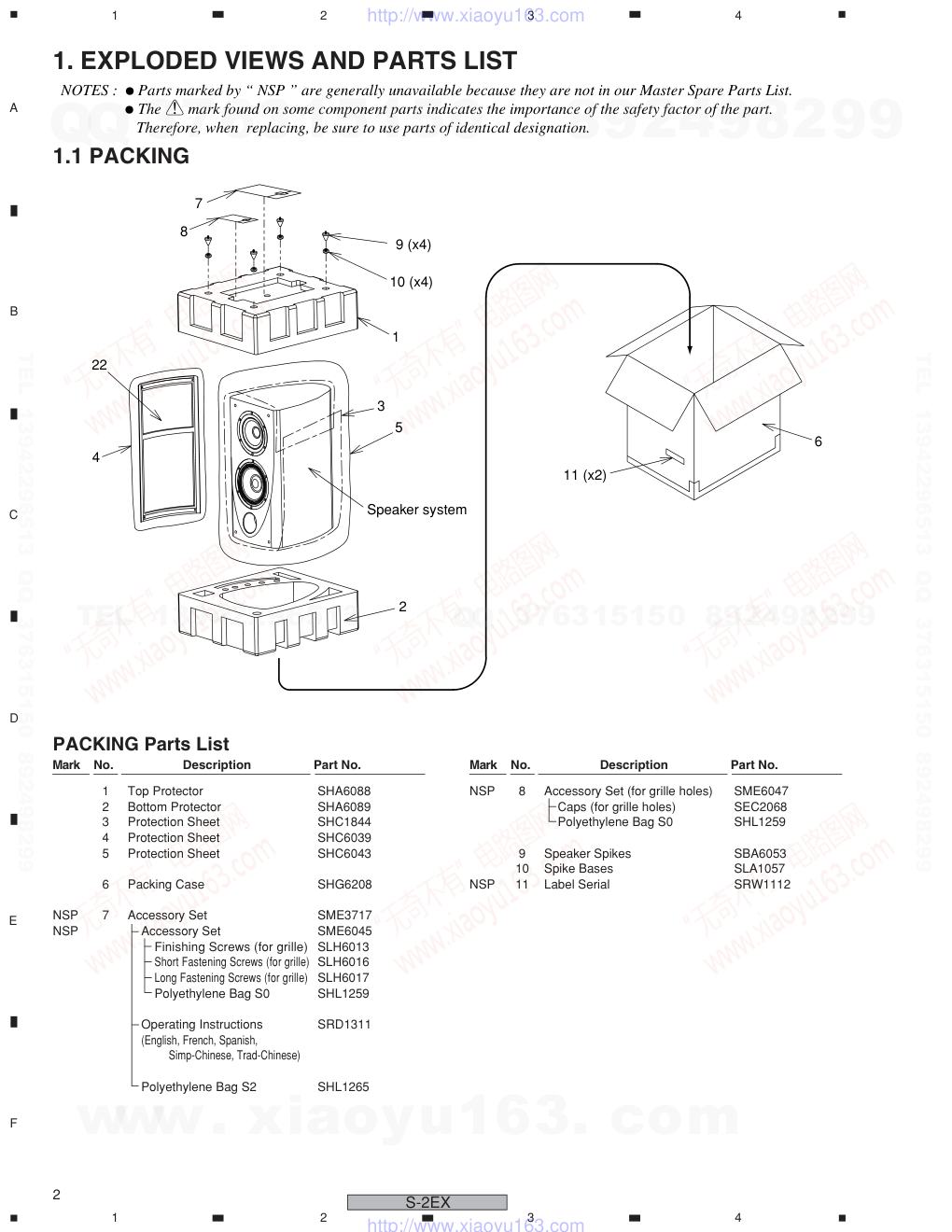
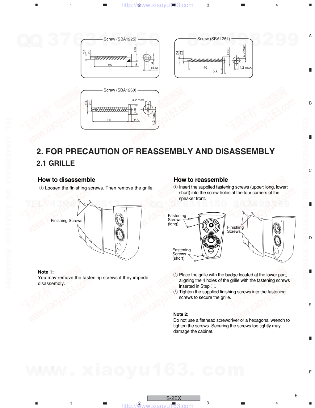
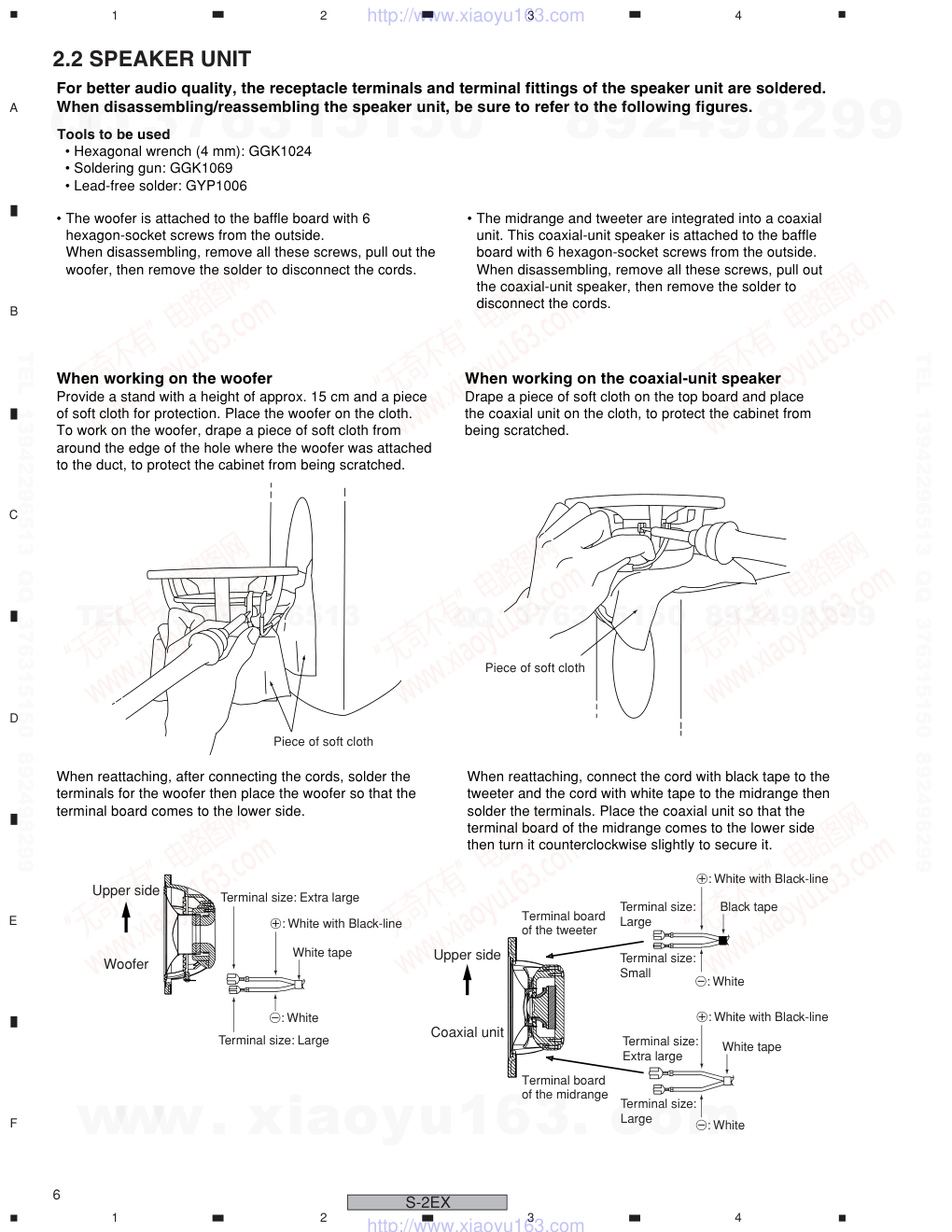
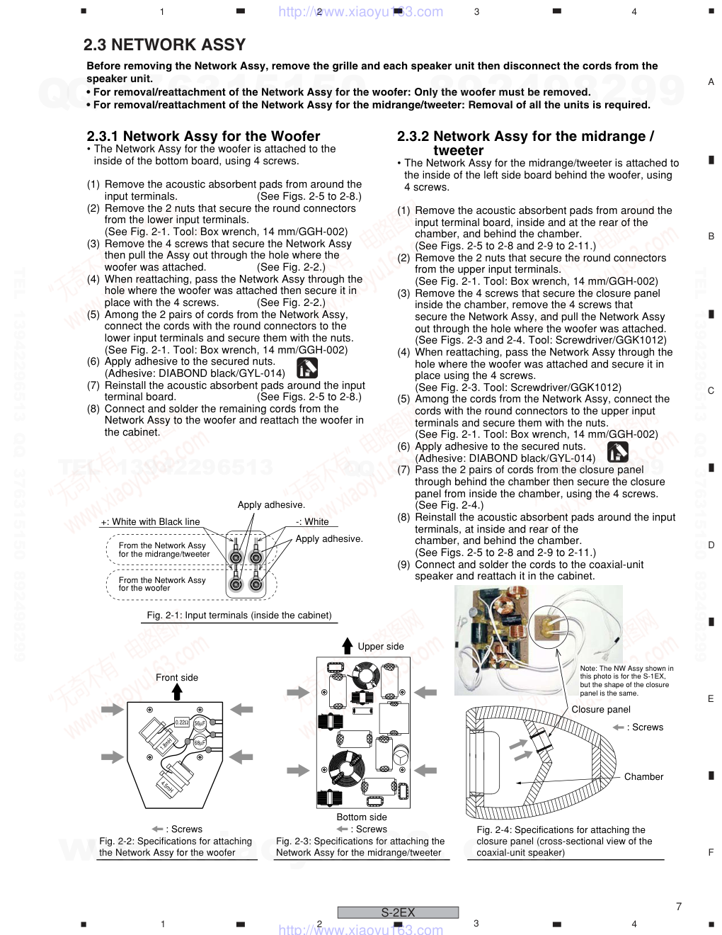
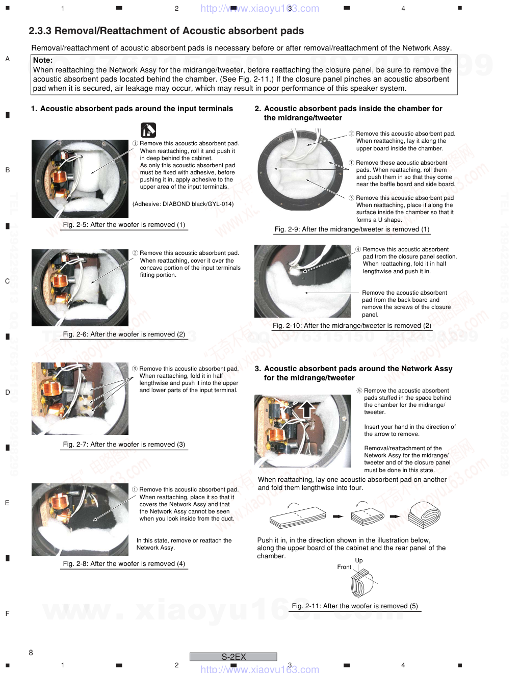
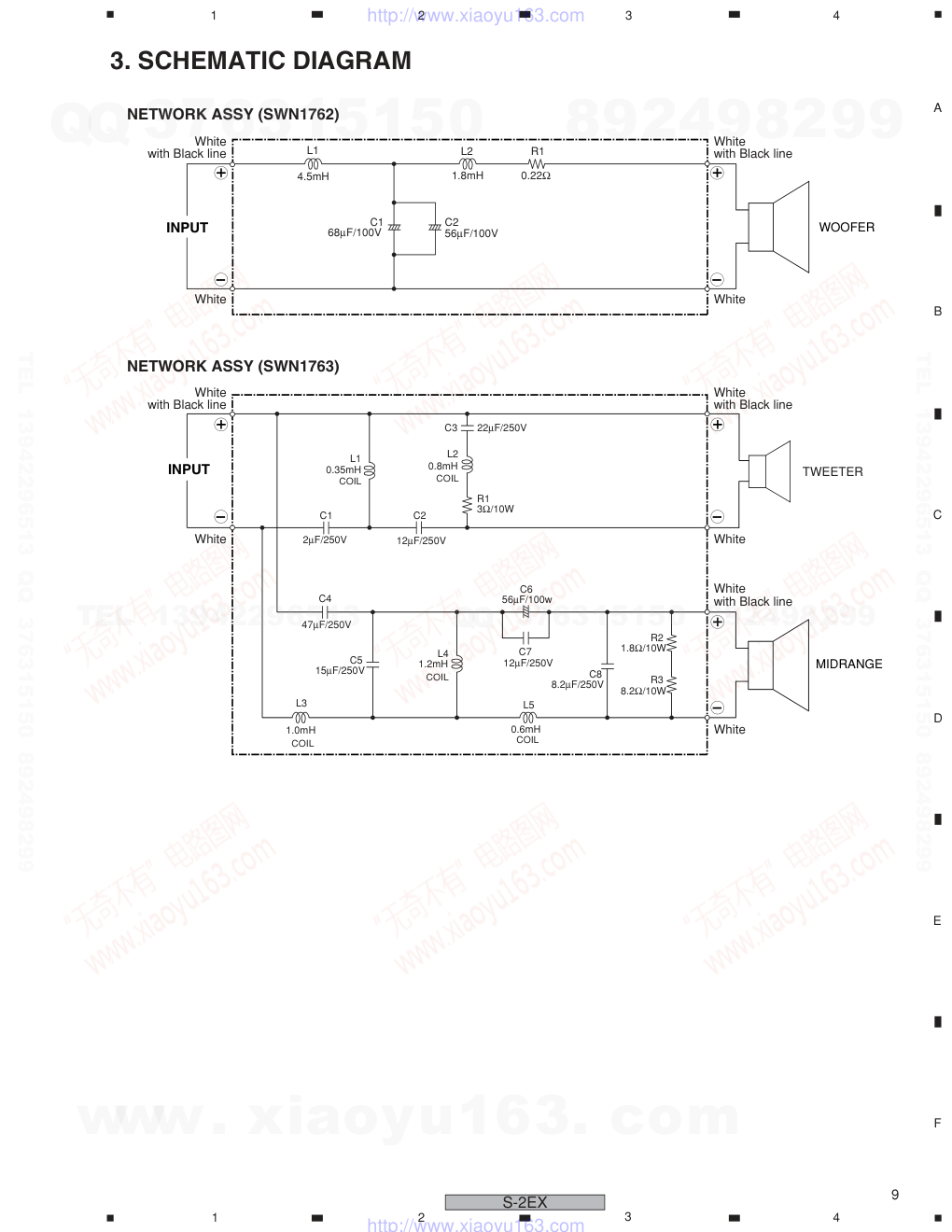
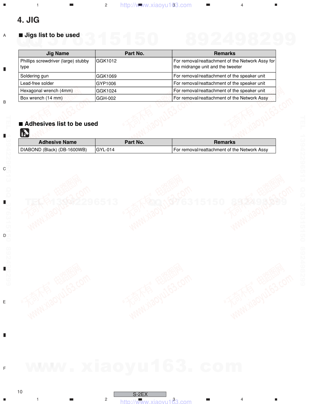
ORDER NO. PIONEER CORPORATION 4-1, Meguro 1-chome, Meguro-ku, Tokyo 153-8654, Japan PIONEER ELECTRONICS (USA) INC. P.O. Box 1760, Long Beach, CA 90801-1760, U.S.A. PIONEER EUROPE NV Haven 1087, Keetberglaan 1, 9120 Melsele, Belgium PIONEER ELECTRONICS ASIACENTRE PTE. LTD. 253 Alexandra Road, #04-01, Singapore 159936 PIONEER CORPORATION 2006 RRV3338 CONTENTS 1. PARTS LIST ................................................................................. 2 2. FOR PRECAUTION OF REASSEMBLY AND DISASSEMBLY ... 5 3. SCHEMATIC DIAGRAM ............................................................... 9 4. JIG .............................................................................................. 10 T – ZZS FEB. 2006 Printed in Japan NOTE For better audio quality, the receptacle terminals and terminal fittings of the speaker unit are soldered. When disassembling/reassembling the speaker unit, be sure to follow the instructions in this manual. If you will be working on the speaker unit with it turned on its side, lay it on a piece of soft cloth, etc., to protect the cabinet from being scratched. SPEAKER SYSTEM S-2EX XTW/E This service manual is intended for qualified service technicians; it is not meant for the casual do-it- yourselfer. Qualified technicians have the necessary test equipment and tools, and have been trained to properly and safely repair complex products such as those covered by this manual. Improperly performed repairs can adversely affect the safety and reliability of the product and may void the warranty. If you are not qualified to perform the repair of this product properly and safely, you should not risk trying to do so and refer the repair to a qualified service technician. WARNING This product contains lead in solder and certain electrical parts contain chemicals which are known to the state of California to cause cancer, birth defects or other reproductive harm. Health & Safety Code Section 25249.6 – Proposition 65 www. xiaoyu163. com QQ 376315150 9 9 2 8 9 4 2 9 8 TEL 13942296513 9 9 2 8 9 4 2 9 8 0 5 1 5 1 3 6 7 3 Q Q TEL 13942296513 QQ 376315150 892498299 TEL 13942296513 QQ 376315150 892498299 http://www.xiaoyu163.com 2 1 2 3 4 1 2 3 4 C D F A B E S-2EX 1 Top Protector SHA6088 2 Bottom Protector SHA6089 3 Protection Sheet SHC1844 4 Protection Sheet SHC6039 5 Protection Sheet SHC6043 6 Packing Case SHG6208 NSP 7 Accessory Set SME3717 NSP Accessory Set SME6045 Finishing Screws (for grille) SLH6013 Short Fastening Screws (for grille) SLH6016 Long Fastening Screws (for grille) SLH6017 Polyethylene Bag S0 SHL1259 Operating Instructions SRD1311 (English, French, Spanish, Simp-Chinese, Trad-Chinese) Polyethylene Bag S2 SHL1265 NSP 8 Accessory Set (for grille holes) SME6047 Caps (for grille holes) SEC2068 Polyethylene Bag S0 SHL1259 9 Speaker Spikes SBA6053 10 Spike Bases SLA1057 NSP 11 Label Serial SRW1112 1. EXPLODED VIEWS AND PARTS LIST 7 8 4 9 (x4) 10 (x4) 1 5 3 2 6 22 Speaker system 11 (x2) 1.1 PACKING PACKING Parts List Mark No. Description Part No. Mark No. Description Part No. NOTES : ÷ Parts marked by “ NSP ” are generally unavailable because they are not in our Master Spare Parts List. ÷ The > mark found on some component parts indicates the importance of the safety factor of the part. Therefore, when replacing, be sure to use parts of identical designation. www. xiaoyu163. com QQ 376315150 9 9 2 8 9 4 2 9 8 TEL 13942296513 9 9 2 8 9 4 2 9 8 0 5 1 5 1 3 6 7 3 Q Q TEL 13942296513 QQ 376315150 892498299 TEL 13942296513 QQ 376315150 892498299 http://www.xiaoyu163.com 3 1 2 3 4 1 2 3 4 C D F A B E S-2EX Lower side for the LPF input terminals Upper side for the HPF input terminals Connect the cords with white tape to the midrange unit. Connect the cords with black tape to the tweeter. 30 21 39 38 40 (x6 /unit) 34 33 41 (x8) 29 42 (x4) 35 (x4) A B A' : Refer to the adhesive points on page 7 (30) A-A' Sectional view NSP 21 Cabinet SMM2028 NSP Fung Nut M5 (for stand) SBN1065 NSP Fung Nut M4 (for grille) SBN1066 NSP Fung Nut M6 (for spike) SBN1068 29 Network Assy (low pass) SWN1762 30 Network Assy (high pass) SWN1763 NSP 33 Gasket (for MID/TW) SEC2031 NSP 34 Gasket (for WF) SEC2032 NSP 35 Gasket (cabinet-input terminals) SEC2065 38 Speaker (WF) B18IU60-52D 39 Speaker (MID/TW) A14GR55-52DX 40 Hexagon Socket Screw SBA1225 (for WF, MID/TW) 41 Screw (for NW assy) SBA1260 42 Screw (for closure panel) SBA1261 1.2 SPEAKER SYSTEM Mark No. Description Part No. NSP Acoustic Absorbent SMT1313 (behind chamber, WF) NSP Acoustic Absorbent (inside chamber) SMT1314 NSP Acoustic Absorbent (inside chamber) SMT1316 NSP Acoustic Absorbent (under chamber) SMT1319 NSP Acoustic Absorbent SMT1320 (chamber/holes, input terminals) NSP Acoustic Absorbent SMT1322 (input terminals) NSP Acoustic Absorbent SMT1323 (behind WF, black) NSP Acoustic Absorbent SMT1324 (duct board side, right side board) NSP Acoustic Absorbent SMT1325 (upper short side of duct board) Mark No. Description Part No. SPEAKER SYSTEM Parts List www. xiaoyu163. com QQ 376315150 9 9 2 8 9 4 2 9 8 TEL 13942296513 9 9 2 8 9 4 2 9 8 0 5 1 5 1 3 6 7 3 Q Q TEL 13942296513 QQ 376315150 892498299 TEL 13942296513 QQ 376315150 892498299 http://www.xiaoyu163.com 4 1 2 3 4 1 2 3 4 C D F A B E S-2EX 32 32 37 31 43 45 44 36 The direction of the cord holes must be vertical. The direction of the cord holes must be vertical. HPF input (+) LPF input (+) HPF input (-) LPF input (-) Arrow view B: Detail of the input terminal board 23 24 25 27 28 26 No.22 Grille Front View Back View 22 Grille SMG6097 23 Badge FRAM-048 24 Packing SEC6060 NSP 25 Grille Assy SMG6098 NSP 26 Fung Nut SBN6019 NSP 27 Grille Frame SMC6004 NSP 28 Punching Net SNH6015 NSP 31 Stiker SAN3871 32 Cord SDS1192 36 Input Terminal (Red) SKX6027 37 Input Terminal (Black) SKX6028 Mark No. Description Part No. NSP 43 Model Label SAN3791 NSP 44 Country Label SAN3782 NSP 45 Label Serial SRW1111 Mark No. Description Part No. SPEAKER SYSTEM Parts List www. xiaoyu163. com QQ 376315150 9 9 2 8 9 4 2 9 8 TEL 13942296513 9 9 2 8 9 4 2 9 8 0 5 1 5 1 3 6 7 3 Q Q TEL 13942296513 QQ 376315150 892498299 TEL 13942296513 QQ 376315150 892498299 http://www.xiaoyu163.com 5 1 2 3 4 1 2 3 4 C D F A B E S-2EX 2. FOR PRECAUTION OF REASSEMBLY AND DISASSEMBLY 2.1 GRILLE How to disassemble 1 Loosen the finishing screws. Then remove the grille. Note 1: You may remove the fastening screws if they impede disassembly. How to reassemble Finishing Screws Finishing Screws 2 Place the grille with the badge located at the lower part, aligning the 4 holes of the grille with the fastening screws inserted in Step 1. 3 Tighten the supplied finishing screws into the fastening screws to secure the grille. Note 2: Do not use a flathead screwdriver or a hexagonal wrench to tighten the screws. Securing the screws too tightly may damage the cabinet. 1 Insert the supplied fastening screws (upper: long, lower: short) into the screw holes at the four corners of the speaker front. Fastening Screws (long) Fastening Screws (short) ∅3 ∅4 35 5 ∅8.5 4 (4.6) Screw (SBA1225) ∅3 ∅4 ∅8.3 2.5 30 4.2 max. 4.2 max. Screw (SBA1260) 4.2 max. ∅8.3 ∅3 ∅4 40 2.5 4.2 max. Screw (SBA1261) www. xiaoyu163. com QQ 376315150 9 9 2 8 9 4 2 9 8 TEL 13942296513 9 9 2 8 9 4 2 9 8 0 5 1 5 1 3 6 7 3 Q Q TEL 13942296513 QQ 376315150 892498299 TEL 13942296513 QQ 376315150 892498299 http://www.xiaoyu163.com 6 1 2 3 4 1 2 3 4 C D F A B E S-2EX 2.2 SPEAKER UNIT White tape White tape Black tape Terminal size: Extra large Terminal size: Extra large Terminal size: Large Terminal size: Large Terminal size: Large Terminal size: Small �: White with Black-line �: White with Black-line �: White with Black-line �: White �: White �: White Woofer Upper side Upper side Coaxial unit Terminal board of the tweeter Terminal board of the midrange For better audio quality, the receptacle terminals and terminal fittings of the speaker unit are soldered. When disassembling/reassembling the speaker unit, be sure to refer to the following figures. Piece of soft cloth Piece of soft cloth Tools to be used • Hexagonal wrench (4 mm): GGK1024 • Soldering gun: GGK1069 • Lead-free solder: GYP1006 • The woofer is attached to the baffle board with 6 hexagon-socket screws from the outside. When disassembling, remove all these screws, pull out the woofer, then remove the solder to disconnect the cords. When working on the woofer Provide a stand with a height of approx. 15 cm and a piece of soft cloth for protection. Place the woofer on the cloth. To work on the woofer, drape a piece of soft cloth from around the edge of the hole where the woofer was attached to the duct, to protect the cabinet from being scratched. When working on the coaxial-unit speaker Drape a piece of soft cloth on the top board and place the coaxial unit on the cloth, to protect the cabinet from being scratched. • The midrange and tweeter are integrated into a coaxial unit. This coaxial-unit speaker is attached to the baffle board with 6 hexagon-socket screws from the outside. When disassembling, remove all these screws, pull out the coaxial-unit speaker, then remove the solder to disconnect the cords. When reattaching, after connecting the cords, solder the terminals for the woofer then place the woofer so that the terminal board comes to the lower side. When reattaching, connect the cord with black tape to the tweeter and the cord with white tape to the midrange then solder the terminals. Place the coaxial unit so that the terminal board of the midrange comes to the lower side then turn it counterclockwise slightly to secure it. www. xiaoyu163. com QQ 376315150 9 9 2 8 9 4 2 9 8 TEL 13942296513 9 9 2 8 9 4 2 9 8 0 5 1 5 1 3 6 7 3 Q Q TEL 13942296513 QQ 376315150 892498299 TEL 13942296513 QQ 376315150 892498299 http://www.xiaoyu163.com 7 1 2 3 4 1 2 3 4 C D F A B E S-2EX 2.3 NETWORK ASSY Before removing the Network Assy, remove the grille and each speaker unit then disconnect the cords from the speaker unit. • For removal/reattachment of the Network Assy for the woofer: Only the woofer must be removed. • For removal/reattachment of the Network Assy for the midrange/tweeter: Removal of all the units is required. 2.3.1 Network Assy for the Woofer • The Network Assy for the woofer is attached to the inside of the bottom board, using 4 screws. (1) Remove the acoustic absorbent pads from around the input terminals. (See Figs. 2-5 to 2-8.) (2) Remove the 2 nuts that secure the round connectors from the lower input terminals. (See Fig. 2-1. Tool: Box wrench, 14 mm/GGH-002) (3) Remove the 4 screws that secure the Network Assy then pull the Assy out through the hole where the woofer was attached. (See Fig. 2-2.) (4) When reattaching, pass the Network Assy through the hole where the woofer was attached then secure it in place with the 4 screws. (See Fig. 2-2.) (5) Among the 2 pairs of cords from the Network Assy, connect the cords with the round connectors to the lower input terminals and secure them with the nuts. (See Fig. 2-1. Tool: Box wrench, 14 mm/GGH-002) (6) Apply adhesive to the secured nuts. (Adhesive: DIABOND black/GYL-014) (7) Reinstall the acoustic absorbent pads around the input terminal board. (See Figs. 2-5 to 2-8.) (8) Connect and solder the remaining cords from the Network Assy to the woofer and reattach the woofer in the cabinet. 2.3.2 Network Assy for the midrange / tweeter • The Network Assy for the midrange/tweeter is attached to the inside of the left side board behind the woofer, using 4 screws. (1) Remove the acoustic absorbent pads from around the input terminal board, inside and at the rear of the chamber, and behind the chamber. (See Figs. 2-5 to 2-8 and 2-9 to 2-11.) (2) Remove the 2 nuts that secure the round connectors from the upper input terminals. (See Fig. 2-1. Tool: Box wrench, 14 mm/GGH-002) (3) Remove the 4 screws that secure the closure panel inside the chamber, remove the 4 screws that secure the Network Assy, and pull the Network Assy out through the hole where the woofer was attached. (See Figs. 2-3 and 2-4. Tool: Screwdriver/GGK1012) (4) When reattaching, pass the Network Assy through the hole where the woofer was attached and secure it in place using the 4 screws. (See Fig. 2-3. Tool: Screwdriver/GGK1012) (5) Among the cords from the Network Assy, connect the cords with the round connectors to the upper input terminals and secure them with the nuts. (See Fig. 2-1. Tool: Box wrench, 14 mm/GGH-002) (6) Apply adhesive to the secured nuts. (Adhesive: DIABOND black/GYL-014) (7) Pass the 2 pairs of cords from the closure panel through behind the chamber then secure the closure panel from inside the chamber, using the 4 screws. (See Fig. 2-4.) (8) Reinstall the acoustic absorbent pads around the input terminals, at inside and rear of the chamber, and behind the chamber. (See Figs. 2-5 to 2-8 and 2-9 to 2-11.) (9) Connect and solder the cords to the coaxial-unit speaker and reattach it in the cabinet. Fig. 2-1: Input terminals (inside the cabinet) Fig. 2-2: Specifications for attaching the Network Assy for the woofer Fig. 2-3: Specifications for attaching the Network Assy for the midrange/tweeter Fig. 2-4: Specifications for attaching the closure panel (cross-sectional view of the coaxial-unit speaker) +: White with Black line : Screws : Screws : Screws Chamber Closure panel From the Network Assy for the midrange/tweeter From the Network Assy for the woofer Apply adhesive. Apply adhesive. -: White Bottom side Note: The NW Assy shown in this photo is for the S-1EX, but the shape of the closure panel is the same. Front side 0.22Ω 56µF 68µF 4.5mH 1.8mH Upper side www. xiaoyu163. com QQ 376315150 9 9 2 8 9 4 2 9 8 TEL 13942296513 9 9 2 8 9 4 2 9 8 0 5 1 5 1 3 6 7 3 Q Q TEL 13942296513 QQ 376315150 892498299 TEL 13942296513 QQ 376315150 892498299 http://www.xiaoyu163.com 8 1 2 3 4 1 2 3 4 C D F A B E S-2EX 2.3.3 Removal/Reattachment of Acoustic absorbent pads Note: When reattaching the Network Assy for the midrange/tweeter, before reattaching the closure panel, be sure to remove the acoustic absorbent pads located behind the chamber. (See Fig. 2-11.) If the closure panel pinches an acoustic absorbent pad when it is secured, air leakage may occur, which may result in poor performance of this speaker system. Removal/reattachment of acoustic absorbent pads is necessary before or after removal/reattachment of the Network Assy. 1. Acoustic absorbent pads around the input terminals 2. Acoustic absorbent pads inside the chamber for the midrange/tweeter 3. Acoustic absorbent pads around the Network Assy for the midrange/tweeter Fig. 2-5: After the woofer is removed (1) Fig. 2-6: After the woofer is removed (2) Fig. 2-7: After the woofer is removed (3) Fig. 2-8: After the woofer is removed (4) Fig. 2-9: After the midrange/tweeter is removed (1) Fig. 2-10: After the midrange/tweeter is removed (2) 3 Remove this acoustic absorbent pad. When reattaching, fold it in half lengthwise and push it into the upper and lower parts of the input terminal. 1 Remove this acoustic absorbent pad. When reattaching, place it so that it covers the Network Assy and that the Network Assy cannot be seen when you look inside from the duct. 1 Remove this acoustic absorbent pad. When reattaching, roll it and push it in deep behind the cabinet. As only this acoustic absorbent pad must be fixed with adhesive, before pushing it in, apply adhesive to the upper area of the input terminals. 2 Remove this acoustic absorbent pad. When reattaching, lay it along the upper board inside the chamber. 1 Remove these acoustic absorbent pads. When reattaching, roll them and push them in so that they come near the baffle board and side board. 3 Remove this acoustic absorbent pad When reattaching, place it along the surface inside the chamber so that it forms a U shape. 4 Remove this acoustic absorbent pad from the closure panel section. When reattaching, fold it in half lengthwise and push it in. Remove the acoustic absorbent pad from the back board and remove the screws of the closure panel. 5 Remove the acoustic absorbent pads stuffed in the space behind the chamber for the midrange/ tweeter. Insert your hand in the direction of the arrow to remove. Removal/reattachment of the Network Assy for the midrange/ tweeter and of the closure panel must be done in this state. 2 Remove this acoustic absorbent pad. When reattaching, cover it over the concave portion of the input terminals fitting portion. (Adhesive: DIABOND black/GYL-014) In this state, remove or reattach the Network Assy. When reattaching, lay one acoustic absorbent pad on another and fold them lengthwise into four. Push it in, in the direction shown in the illustration below, along the upper board of the cabinet and the rear panel of the chamber. Fig. 2-11: After the woofer is removed (5) Up Front www. xiaoyu163. com QQ 376315150 9 9 2 8 9 4 2 9 8 TEL 13942296513 9 9 2 8 9 4 2 9 8 0 5 1 5 1 3 6 7 3 Q Q TEL 13942296513 QQ 376315150 892498299 TEL 13942296513 QQ 376315150 892498299 http://www.xiaoyu163.com 9 1 2 3 4 1 2 3 4 C D F A B E S-2EX NETWORK ASSY (SWN1762) NETWORK ASSY (SWN1763) L1 L2 R1 3Ω/10W 0.35mH 0.8mH C1 C4 C5 L3 L4 1.2mH 15µF/250V 56µF/100w 12µF/250V 8.2µF/250V C6 C7 C8 1.8Ω/10W R2 8.2Ω/10W R3 L5 0.6mH 1.0mH C2 C3 22µF/250V 12µF/250V 2µF/250V 47µF/250V INPUT INPUT White with Black line White with Black line L2 R1 L1 C1 C2 56µF/100V 68µF/100V 4.5mH 1.8mH 0.22Ω White White with Black line White White White with Black line White White with Black line White COIL COIL COIL COIL COIL WOOFER MIDRANGE TWEETER 3. SCHEMATIC DIAGRAM www. xiaoyu163. com QQ 376315150 9 9 2 8 9 4 2 9 8 TEL 13942296513 9 9 2 8 9 4 2 9 8 0 5 1 5 1 3 6 7 3 Q Q TEL 13942296513 QQ 376315150 892498299 TEL 13942296513 QQ 376315150 892498299 http://www.xiaoyu163.com 10 1 2 3 4 1 2 3 4 C D F A B E S-2EX 4. JIG Soldering gun Phillips screwdriver (large) stubby type GGK1069 GGK1012 For removal/reattachment of the Network Assy for the midrange unit and the tweeter For removal/reattachment of the speaker unit Jig Name Part No. Remarks Lead-free solder GYP1006 For removal/reattachment of the speaker unit 7 Jigs list to be used Hexagonal wrench (4mm) GGK1024 For removal/reattachment of the speaker unit Box wrench (14 mm) GGH-002 For removal/reattachment of the Network Assy DIABOND (Black) (DB-1600WB) GYL-014 For removal/reattachment of the Network Assy Adhesive Name Part No. Remarks 7 Adhesives list to be used www. xiaoyu163. com QQ 376315150 9 9 2 8 9 4 2 9 8 TEL 13942296513 9 9 2 8 9 4 2 9 8 0 5 1 5 1 3 6 7 3 Q Q TEL 13942296513 QQ 376315150 892498299 TEL 13942296513 QQ 376315150 892498299 http://www.xiaoyu163.com
版权声明
1. 本站所有素材,仅限学习交流,仅展示部分内容,如需查看完整内容,请下载原文件。
2. 会员在本站下载的所有素材,只拥有使用权,著作权归原作者所有。
3. 所有素材,未经合法授权,请勿用于商业用途,会员不得以任何形式发布、传播、复制、转售该素材,否则一律封号处理。
4. 如果素材损害你的权益请联系客服QQ:77594475 处理。