三星E2320液晶显示器维修手册和原理图
 "三星E2320液晶显示器维修手册和原理图-0")
 "三星E2320液晶显示器维修手册和原理图-1")
 "三星E2320液晶显示器维修手册和原理图-2")
 "三星E2320液晶显示器维修手册和原理图-3")
 "三星E2320液晶显示器维修手册和原理图-4")
 "三星E2320液晶显示器维修手册和原理图-5")
 "三星E2320液晶显示器维修手册和原理图-6")
 "三星E2320液晶显示器维修手册和原理图-7")
 "三星E2320液晶显示器维修手册和原理图-8")
 "三星E2320液晶显示器维修手册和原理图-9")
LCD-Monitor
Chassis : LCL23ZS
Model
: E2320
E2320X
SERVICE
Manual
TFT-LCD Monitor
Contens
E2320 / E2320X
Refer to the service manual in the GSPN (see the rear cover) for the more information.
1. Precautions
2. Product specifications
3. Disassembly and Reassemble
4. Troubleshooting
5. Exploded View & Part List
6. Wiring Diagram
Contents
1. Precautions
1-1. Safety Precautions ......................................................................................................... 1-1
1-2. Servicing Precautions ..................................................................................................... 1-2
1-3. Static Electricity Precautions .......................................................................................... 1-2
1-4. Installation Precautions .................................................................................................. 1-3
2. Product specifications
2-1. Feature & Specifications ................................................................................................. 2-1
2-2. Spec Comparison to the Old Models .............................................................................. 2-4
2-3. Accessories .................................................................................................................... 2-6
3. Disassembly and Assembly
3-1. Disassembly ................................................................................................................... 3-1
4. Troubleshooting
4-1. Troubleshooting .............................................................................................................. 4-1
4-2. When the Power Does Not Turn On ............................................................................... 4-2
4-3. When the screen is blank ............................................................................................... 4-4
4-4. Error Examples and Actions ........................................................................................... 4-8
4-5. Adjustment ...................................................................................................................... 4-9
5. Exploded View & Part List
5-1. Exploded View ................................................................................................................ 5-1
5-2. Parts List ......................................................................................................................... 5-3
6. Wiring Diagram
6-1. Wiring Diagram - Main Board ......................................................................................... 6-1
6-2. Wiring Diagram - IP Board .............................................................................................. 6-4
6-3. Connector Functions ...................................................................................................... 6-5
6-4. Cables ............................................................................................................................ 6-5
GSPN (Global Service Partner Network)
Area
Web Site
North America
http://service.samsungportal.com
Latin America
http://latin.samsungportal.com
CIS
http://cis.samsungportal.com
Europe
http://europe.samsungportal.com
China
http://china.samsungportal.com
Asia
http://asia.samsungportal.com
Mideast & Africa
http://mea.samsungportal.com
This Service Manual is a property of Samsung Electronics Co.,Ltd.
Any unauthorized use of Manual can be punished under applicable
International and/or domestic law.
© 2010 Samsung Electronics Co.,Ltd.
All rights reserved.
Printed in Korea
P/N: BN82-00993A-00
3-1
3. Disassembly and Assembly
3. Disassembly and Assembly
This section describes the disassembly and reassembly sequences for this monitor.
Warning:
As this monitor has parts that are sensitive to static electricity, be careful when handling them.
3-1. Disassembly
Caution:
1. Turn the monitor off before beginning the disassembly process.
2. When disassembling the monitor, do not use any metal tools except for the provided jig.
3. Disassemble the monitor carefully as directed in the following procedures.
Description
Photo
Screws
1. Remove the stand body.
2. ① Turn the monitor over and insert your hands
into the top of the monitor at the center and
separate the front cover in the direction of the
arrow as shown in the figure.
② Separate the sides of the front cover up to the
directed line as shown in the figure.
3-2
3. Disassembly and Assembly
Description
Photo
Screws
3. Turn the monitor over again .
3-3
3. Disassembly and Assembly
Description
Photo
Screws
4. Turn the monitor over again to remove the back
cover.
5. Remove the LVDS, LAMP wire and FUNCTION
cable then remove the SHIELD-COVER.
LAMP
WIRE
LVDS
FUNCTION
6. Remove the LCD panel.
7. Remove the four (4) screws shown in the figure.
3-4
3. Disassembly and Assembly
Description
Photo
Screws
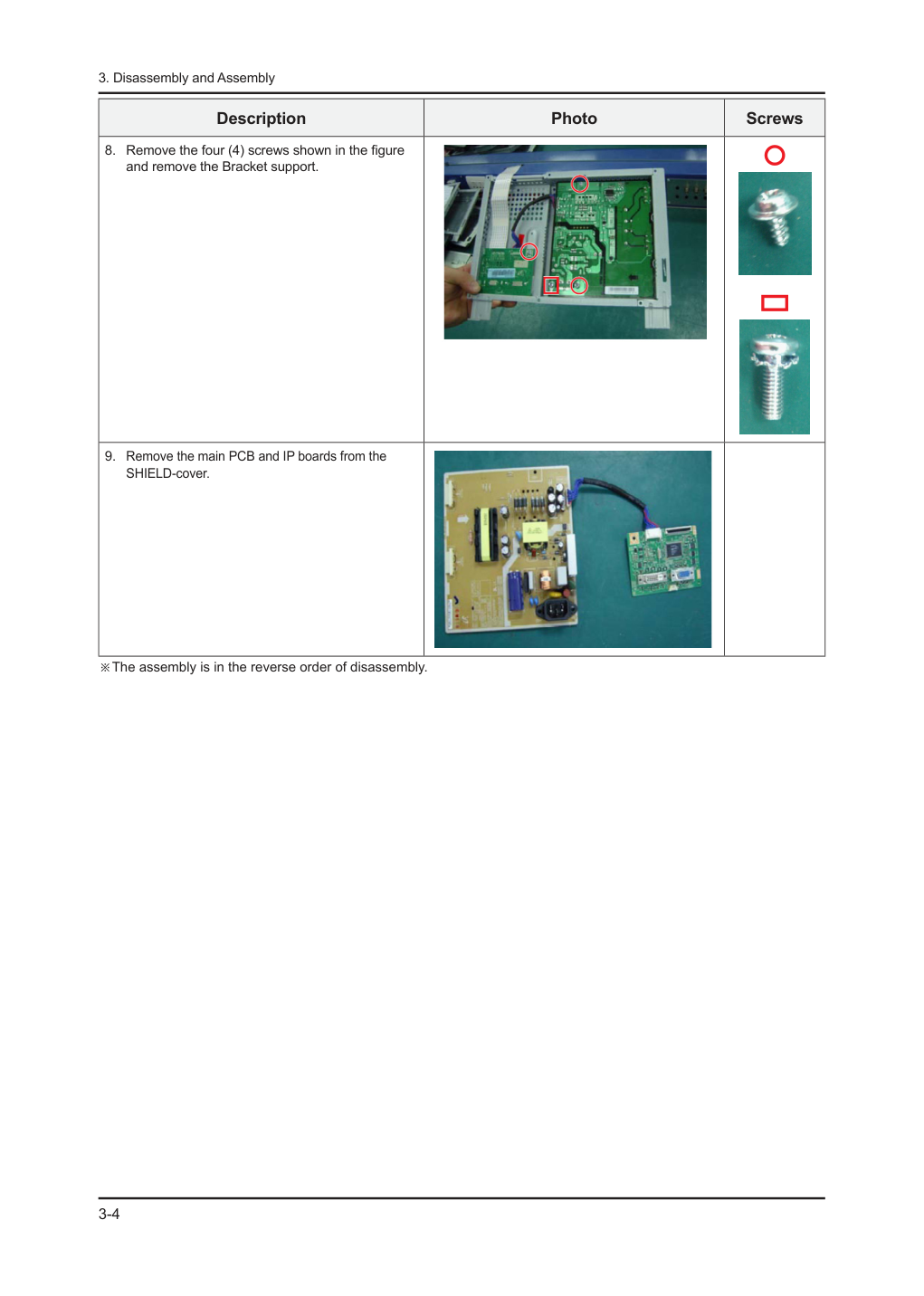
8. Remove the four (4) screws shown in the figure
and remove the Bracket support.
9. Remove the main PCB and IP boards from the
SHIELD-cover.
※The assembly is in the reverse order of disassembly.
5-1
5. Exploded View & Part List
5. Exploded View & Part List
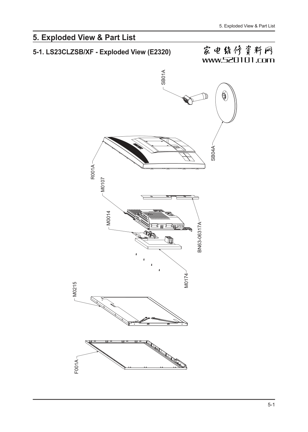
5-1. LS23CLZSB/XF - Exploded View (E2320)
F001A
M0215
M0014
M0107
R001A
SB01A
SB04A
BN63-06317A
M0174
5-2
5. Exploded View & Part List
5-1-1. LS23CLZSB/XF - Parts List
Location No.
Code No.
Description & Specification
Q’ty
SA/SNA
Remark
F001A
BN96-13088B
ASSY COVER P-FRONT;E2320,ABS,HB,BK23,SIM
1
SA
M0014
BN94-03397A
ASSY PCB MAIN-STZ;E2320,STZ
1
SA
M0107
BN63-06316B
SHIELD-COVER;PLUM 23,SECC,T0.8,DUAL
1
SNA
M0174
BN44-00323A
IP BOARD;PWI2304PC(A),PLUM23,23.6,24"w,0
1
SA
M0215
BN07-00609A
LCD-PANEL;LTM230HT01,SSRZTS,6Bit + Hi-FR
1
SA
R001A
BN96-13099A
ASSY COVER P-REAR;Cobalt E2320, E2320X,H
1
SA
SB01A
BN96-12853A
ASSY STAND P-BODY;COBALT,HIPS,BK23,ETCH
1
SA
SB04A
BN96-12977A
ASSY STAND P-BASE;COBALT ,19N,21.5~23,HI
1
SA
BN63-06317A
SHIELD-LAMP;PLUM 23'',SPTE,T0.3
1
SNA
5-3
5. Exploded View & Part List
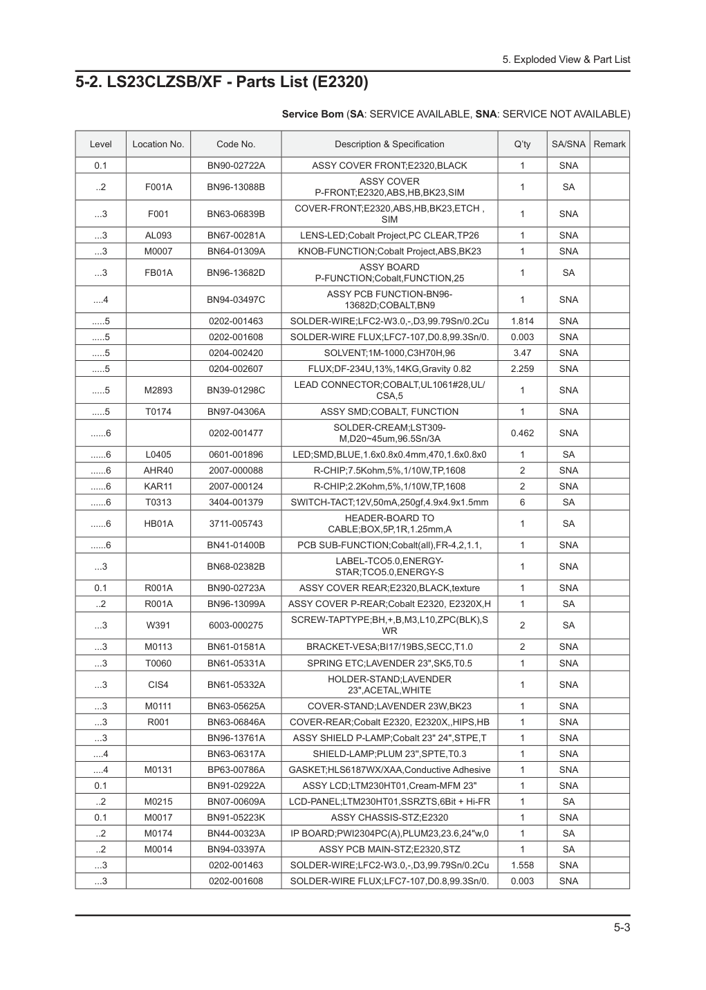
5-2. LS23CLZSB/XF - Parts List (E2320)
Service Bom (SA: SERVICE AVAILABLE, SNA: SERVICE NOT AVAILABLE)
Level
Location No.
Code No.
Description & Specification
Q’ty
SA/SNA
Remark
0.1
BN90-02722A
ASSY COVER FRONT;E2320,BLACK
1
SNA
..2
F001A
BN96-13088B
ASSY COVER
P-FRONT;E2320,ABS,HB,BK23,SIM
1
SA
...3
F001
BN63-06839B
COVER-FRONT;E2320,ABS,HB,BK23,ETCH ,
SIM
1
SNA
...3
AL093
BN67-00281A
LENS-LED;Cobalt Project,PC CLEAR,TP26
1
SNA
...3
M0007
BN64-01309A
KNOB-FUNCTION;Cobalt Project,ABS,BK23
1
SNA
...3
FB01A
BN96-13682D
ASSY BOARD
P-FUNCTION;Cobalt,FUNCTION,25
1
SA
....4
BN94-03497C
ASSY PCB FUNCTION-BN96-
13682D;COBALT,BN9
1
SNA
.....5
0202-001463
SOLDER-WIRE;LFC2-W3.0,-,D3,99.79Sn/0.2Cu
1.814
SNA
.....5
0202-001608
SOLDER-WIRE FLUX;LFC7-107,D0.8,99.3Sn/0.
0.003
SNA
.....5
0204-002420
SOLVENT;1M-1000,C3H70H,96
3.47
SNA
.....5
0204-002607
FLUX;DF-234U,13%,14KG,Gravity 0.82
2.259
SNA
.....5
M2893
BN39-01298C
LEAD CONNECTOR;COBALT,UL1061#28,UL/
CSA,5
1
SNA
.....5
T0174
BN97-04306A
ASSY SMD;COBALT, FUNCTION
1
SNA
......6
0202-001477
SOLDER-CREAM;LST309-
M,D20~45um,96.5Sn/3A
0.462
SNA
......6
L0405
0601-001896
LED;SMD,BLUE,1.6x0.8x0.4mm,470,1.6x0.8x0
1
SA
......6
AHR40
2007-000088
R-CHIP;7.5Kohm,5%,1/10W,TP,1608
2
SNA
......6
KAR11
2007-000124
R-CHIP;2.2Kohm,5%,1/10W,TP,1608
2
SNA
......6
T0313
3404-001379
SWITCH-TACT;12V,50mA,250gf,4.9x4.9x1.5mm
6
SA
......6
HB01A
3711-005743
HEADER-BOARD TO
CABLE;BOX,5P,1R,1.25mm,A
1
SA
......6
BN41-01400B
PCB SUB-FUNCTION;Cobalt(all),FR-4,2,1.1,
1
SNA
...3
BN68-02382B
LABEL-TCO5.0,ENERGY-
STAR;TCO5.0,ENERGY-S
1
SNA
0.1
R001A
BN90-02723A
ASSY COVER REAR;E2320,BLACK,texture
1
SNA
..2
R001A
BN96-13099A
ASSY COVER P-REAR;Cobalt E2320, E2320X,H
1
SA
...3
W391
6003-000275
SCREW-TAPTYPE;BH,+,B,M3,L10,ZPC(BLK),S
WR
2
SA
...3
M0113
BN61-01581A
BRACKET-VESA;BI17/19BS,SECC,T1.0
2
SNA
...3
T0060
BN61-05331A
SPRING ETC;LAVENDER 23",SK5,T0.5
1
SNA
...3
CIS4
BN61-05332A
HOLDER-STAND;LAVENDER
23",ACETAL,WHITE
1
SNA
...3
M0111
BN63-05625A
COVER-STAND;LAVENDER 23W,BK23
1
SNA
...3
R001
BN63-06846A
COVER-REAR;Cobalt E2320, E2320X,,HIPS,HB
1
SNA
...3
BN96-13761A
ASSY SHIELD P-LAMP;Cobalt 23" 24",STPE,T
1
SNA
....4
BN63-06317A
SHIELD-LAMP;PLUM 23'',SPTE,T0.3
1
SNA
....4
M0131
BP63-00786A
GASKET;HLS6187WX/XAA,Conductive Adhesive
1
SNA
0.1
BN91-02922A
ASSY LCD;LTM230HT01,Cream-MFM 23"
1
SNA
..2
M0215
BN07-00609A
LCD-PANEL;LTM230HT01,SSRZTS,6Bit + Hi-FR
1
SA
0.1
M0017
BN91-05223K
ASSY CHASSIS-STZ;E2320
1
SNA
..2
M0174
BN44-00323A
IP BOARD;PWI2304PC(A),PLUM23,23.6,24"w,0
1
SA
..2
M0014
BN94-03397A
ASSY PCB MAIN-STZ;E2320,STZ
1
SA
...3
0202-001463
SOLDER-WIRE;LFC2-W3.0,-,D3,99.79Sn/0.2Cu
1.558
SNA
...3
0202-001608
SOLDER-WIRE FLUX;LFC7-107,D0.8,99.3Sn/0.
0.003
SNA
5-4
5. Exploded View & Part List
Level
Location No.
Code No.
Description & Specification
Q’ty
SA/SNA
Remark
...3
0204-002420
SOLVENT;1M-1000,C3H70H,96
3.47
SNA
...3
0204-002607
FLUX;DF-234U,13%,14KG,Gravity 0.82
2.259
SNA
...3
3701-001510
CONNECTOR-DSUB;15P,3R,FEMAIL,STAMPED
PIN
1
SNA
...3
EC05
3701-001666
CONNECTOR-
DVI;24P,3ROW,FEMALE,STARAIGHT,
1
SA
...3
CN906
3711-005847
CONNECTOR-
HEADER;BOX,9P,1R,2MM,ANGLE,SN,
1
SNA
...3
BN97-00707A
ASSY HDCP;BN46-00018A,BR20/21BS_
CS,MSTAR
1
SNA
....4
BN46-00018A
KEY CODE-CERTIFICATE;(HDCP KEY)
PPM42M5S,
1
SNA
...3
BN97-04137A
ASSY SMD;E2320,STZ,BN94-03397A
1
SNA
....4
0202-001477
SOLDER-CREAM;LST309-
M,D20~45um,96.5Sn/3A
0.795
SNA
....4
DS01A
0401-001056
DIODE-SWITCHING;MMBD4148SE,100V,200m
A,SO
11
SA
....4
DR01A
0402-001614
DIODE-RECTIFIER;S1G,400V,1A,DO-214AC,TP
1
SA
....4
MZD1
0403-001411
DIODE-ZENER;5.49-5.73V,200mW,SOD-323,TP
10
SA
....4
0403-001712
DIODE-ZENER;QZX363C6V8,6.47/7.14V,200mW,
2
SNA
....4
Q101
0501-000445
TR-SMALL SIGNAL;KTC3875S-
Y,NPN,150mW,SOT
1
SA
....4
PQ02
0501-002080
TR-SMALL
SIGNAL;2SC2412K,NPN,200mW,SC-59
3
SA
....4
Q409
0505-001165
FET-SILICON;Si3443CDV,P,-20V,+-4.4A,65mo
1
SA
....4
ND51C2
1001-001155
IC-ANALOG
MULTIPLEX;NC7SB3157P6X,CMOS,SC
1
SA
....4
IC112
1103-000129
IC-EEPROM;24C02,2Kbit,256x8,SOP,8P,5x4mm
2
SA
....4
IC112
1103-001410
IC-EEPROM;S-24CS08AFJ-TB-1GE,8Kbit,1Kx8,
1
SA
....4
T0087
1203-006118
IC-POSI.FIXED REG.;S-1172B18-U5T1G,SOT-8
1
SA
....4
T0087
1203-006141
IC-POSI.FIXED REG.;S-1172B33-U5T1G,SOT-8
1
SA
....4
IC109
1205-003894
IC-LCD CONTROLLER;SE959LMH-
LF,PQFP,128P,
1
SA
....4
DR1
2007-000043
R-CHIP;1Kohm,1%,1/10W,TP,1608
5
SA
....4
KAR21
2007-000070
R-CHIP;0ohm,5%,1/10W,TP,1608
1
SNA
....4
CER02
2007-000071
R-CHIP;22ohm,5%,1/10W,TP,1608
12
SNA
....4
AR30
2007-000074
R-CHIP;100ohm,5%,1/10W,TP,1608
19
SA
....4
AVR51
2007-000083
R-CHIP;3Kohm,5%,1/10W,TP,1608
2
SNA
....4
CER04
2007-000084
R-CHIP;4.7Kohm,5%,1/10W,TP,1608
3
SA
....4
MROP1
2007-000090
R-CHIP;10Kohm,5%,1/10W,TP,1608
22
SA
....4
AR108
2007-000097
R-CHIP;47Kohm,5%,1/10W,TP,1608
7
SA
....4
ARR2
2007-000102
R-CHIP;100Kohm,5%,1/10W,TP,1608
2
SA
....4
MR112
2007-000309
R-CHIP;10ohm,5%,1/10W,TP,1608
2
SA
....4
HR13
2007-000821
R-CHIP;390ohm,1%,1/10W,TP,1608
2
SNA
....4
WR15B
2007-001044
R-CHIP;56ohm,5%,1/10W,TP,1608
2
SA
....4
ZR10
2007-001164
R-CHIP;75ohm,1%,1/10W,TP,1608
3
SNA
....4
R1
2007-002425
R-CHIP;1ohm,5%,1/10W,TP,1608
5
SNA
....4
2007-007720
R-CHIP;300Kohm,1%,1/10W,TP,1608
1
SA
....4
C258
2203-000236
C-CER,CHIP;0.1nF,5%,50V,C0G,1608
3
SA
....4
C134
2203-000257
C-CER,CHIP;10nF,10%,50V,X7R,TP,1608
1
SA
....4
ZC14
2203-000626
C-CER,CHIP;0.022nF,5%,50V,C0G,1608
3
SNA
....4
AAC14
2203-000888
C-CER,CHIP;4.7nF,10%,50V,X7R,TP,1608
6
SA
....4
DC108
2203-005005
C-CER,CHIP;100nF,10%,16V,X7R,1608
47
SC
....4
PC11
2203-006141
C-CER,CHIP;1000nF,10%,16V,X5R,1608
3
SNA
5-5
5. Exploded View & Part List
Level
Location No.
Code No.
Description & Specification
Q’ty
SA/SNA
Remark
....4
C125
2203-006361
C-CER,CHIP;10000nF,10%,10V,X5R,TP,2012
18
SC
....4
X202
2801-003667
CRYSTAL-SMD;14.31818MHz,30ppm,28-
AAN,16p
1
SA
....4
L2011
3301-001145
BEAD-SMD;60ohm,4516,TP,70ohm/45MHz,82o
hm
4
SNA
....4
T0568
3301-001407
BEAD-SMD;30ohm,1608,300mA,TP,,,0.4ohm
2
SNA
....4
AC510
3708-001150
CONNECTOR-FPC/FFC/PIC;30P,1mm,SMD-
A,SN,Y
1
SA
....4
HB01A
3711-005743
HEADER-BOARD TO
CABLE;BOX,5P,1R,1.25mm,A
1
SA
....4
KAR11
2007-000124
R-CHIP;2.2Kohm,5%,1/10W,TP,1608
1
SNA
....4
C3
2203-000384
C-CER,CHIP;0.015nF,5%,50V,C0G,1608
1
SNA
....4
BN97-03976J
ASSY MICOM;B2340,STZ,BN94-03250J
1
SNA
.....5
IC115
1107-001580
IC-FLASH MEMORY;MX25L4005,4Mbit,512Kx8,S
1
SNA
....4
BN41-01311C
PCB MAIN;PLUM B2330,CEM-3,2,MP1.0,1.6,91
1
SNA
..2
M0214
BN96-02854Y
ASSY CABLE P-FLAT;Mckinley,Flat cable,17
1
SA
..2
M0006
BN96-12459B
ASSY SHIELD P-COVER;PLUM
23,SECC,T0.8,DU
1
SNA
...3
BN61-05973A
STUD-PEM;PLUM23'',M4,D8,L20
2
SNA
...3
M0107
BN63-06316B
SHIELD-COVER;PLUM 23,SECC,T0.8,DUAL
1
SNA
...3
M0131
BN63-00049A
GASKET;RB17AS,Conductive Fabric,1.5MM,10
1
SNA
...3
M0114
BN61-02500A
HOLDER-WIRE;NYLON6.6,NATURAL
1
SNA
..2
T0081
6001-002408
SCREW-MACHINE;BH,+,WT,M4,L12,ZPC(WHT
),SW
2
SA
..2
M0081
6003-000264
SCREW-TAPTYPE;PWH,+,-
,B,M3,L6,ZPC(WHT),S
2
SA
0.1
BN91-05280A
ASSY SHIELD;E2320X
1
SNA
..2
CIS1
BN74-00021A
TAPE-FILAMENT;Filament tape,clear,#8915,
0.3
SNA
0.1
BN92-05486D
ASSY LABEL;Cobalt, BLACK
1
SNA
..2
CCM1
BN68-01570A
LABEL RATING;ALL,SS,PE,T0.05,90,45,Dark
1
SNA
0.1
BN92-05547X
ASSY P/MATERIAL;S23S1,LS23CLZSB/EN
1
SNA
..2
T0214
0203-001595
TAPE-OPP MASKING;OPP-2,0.075,75,800M,CLR
1.54
SNA
..2
6902-000061
BAG AIR;LDPE,T0.2,W500,L1000,TRP,370.000
1
SNA
..2
6902-000379
BAG AIR;LDPE,T0.2,W1000,L1800,TRP,1260.0
1
SNA
..2
T0524
6902-000520
BAG PE;HDPE/NITRON,T0.015/
T0.5(DOUBLE),W
1
SNA
..2
6902-000604
BAG WRAPPING;LDPE,T0.02,W500,L10000,TRP,
2.47
SNA
..2
6902-000609
BAG ROLL;LDPE,T0.05,W2400,L1000,TRP,30.0
0.02
SNA
..2
AA69-03810M
PAD-PLATE;CB,SW,1240,800
1
SNA
..2
T0527
BH68-40364A
LABEL-SUMMARY;G52,G72,ART,100G,WHT,BL
K,W
1
SNA
..2
BH69-00457C
PACKING INNER-
00,PAD;COMM,OTHER,T3.0,880
1
SNA
..2
T0527
BN68-00129A
LABEL SHIPPING-00;LABEL SHIPPING,ART-PAP
1
SNA
..2
BN69-00391Y
PAD-ANGLE;CB,T5,W2100,L50,YEL,403g
1
SNA
..2
BN69-03507F
PALLET-WOOD;F2380,WOOD-
OTH,W1265,D835,H1
1
SNA
..2
BN69-04627A
CUSHION-SET;COBALT23",SIMPLE,EPS,T0.018,
1
SNA
0.1
BN92-05761V
ASSY BOX;LS23CLZSB/XF
1
SNA
..2
T0077
BH68-00329D
LABEL BAR CODE-02;NO CE,NO WT`Y,MPRII,LA
1
SNA
..2
BN68-02258M
LABEL-STICKER
HIC;MODEL9,CHINA,MOJO,80G,
1
SNA
..2
BN69-04816A
BOX-02,SET;Cobalt23"(SIMPLE),PAPER,SW,A1
1
SNA
5-6
5. Exploded View & Part List
Level
Location No.
Code No.
Description & Specification
Q’ty
SA/SNA
Remark
..2
BH68-00659H
LABEL BOX-00;ALL MODEL,MOJO
90G,90,95,WH
1
SNA
0.1
ACCE1
BN92-05913M
ASSY ACCESSORY;LS22CLZSB/XF
1
SNA
..2
EC29
BN39-00244H
CBF SIGNAL-D-SUB TO D-SUB;D-sub cable,15
1
SA
..2
SB01A
BN96-12853A
ASSY STAND
P-BODY;COBALT,HIPS,BK23,ETCH
1
SA
...3
W392
6003-000282
SCREW-TAPTYPE;BH,+,-,B,M3,L8,ZPC(BLK),SW
2
SA
...3
T0524
6902-000023
BAG PE;LDPE,T0.08,W150,L120,TRP,1.650g
1
SNA
...3
BN61-06067A
STAND-BAR;COBALT 21.5,HIPS,BK23
1
SNA
....4
BN61-06068A
STAND-BAR IN;COBALT,HIPS,BK23,IN
1
SNA
...3
BN61-06334A
BRACKET-PLATE;COBALT,SECC,1.0,SIMPLE
1
SNA
...3
BN68-02822J
LABEL-STICKER;W/W,ART PAPER,T0.05,50,10,
1
SNA
..2
SB04A
BN96-12977A
ASSY STAND P-BASE;COBALT ,19N,21.5~23,HI
1
SA
...3
M0081
6003-001001
SCREW-TAPTYPE;FH,+,B,M3,L8,ZPC(BLK),SW
RC
4
SNA
...3
T0524
6902-000109
BAG PE;HDPE,T0.015,W350,L430,TRP,28,2,4.
1
SNA
...3
CIS4
BN61-01717A
HOLDER-STAND;BIZET,NI PLT,CH,+,M4,L11(5)
1
SNA
...3
BN61-05087A
BRACKET-STAND BOTTOM;ECOFIT 23",SECC
T0.
1
SNA
...3
BN63-06779A
COVER-STAND BASE;COBALT
19N,21.5~24,HIPS
1
SNA
...3
AR011
BN73-00077A
RUBBER FOOT;MATISSE,BUMPON,#13.5,T2.0
,60
6
SNA
...3
BN68-02691A
MANUAL FLYER-STAND;COBALT,Mojo 80g,148,2
1
SNA
...3
BN68-02822H
LABEL-STICKER;W/W,ART PAPER,T0.05,50,10,
1
SNA
..2
ACCE1
BN96-13553D
ASSY ACCESSORY;LS19CLNSB/XF
1
SA
...3
T0268
3903-000455
CBF-POWER CORD;DT,CN,IP3/Y(A),IEC320 C13
1
SA
...3
T0524
6902-000110
BAG PE;LDPE,T0.05,W250,L400,TRP,28,2,9.2
1
SNA
...3
T0527
AA68-00764A
LABEL-PASSING;SAMSUNG ALL,ART
PAPER,CLR,
1
SNA
...3
T0527
BN68-00513A
LABEL-E,PASS;ALL MODEL,YUPO(110G),50X15,
1
SNA
...3
BN68-01789A
MANUAL FLYER-WARRANTY CARD;Chinese,Art
1
1
SNA
...3
BN68-02528A
MANUAL FLYER-CHINA
MANUAL;Cobalt,SyncMas
1
SNA
...3
BN68-01118D
MANUAL-TCO 5.0 CARD;COMM,W/W,Mojo
80g,21
1
SNA
1-1
1. Precautions
1. Precautions
1-1. Safety Precautions
Follow these safety, servicing and ESD precautions to prevent damage and to protect against potential hazards such as
electrical shock.
1-1-1. Warnings
For continued safety, do not attempt to modify the circuit board.
1.
Disconnect the AC power and DC power jack before servicing.
2.
1-1-2. Servicing the LCD Monitor
When servicing the LCD Monitor, Disconnect the AC line cord from the AC outlet.
1.
It is essential that service technicians have an accurate voltage meter available at all times. Check the calibration of
2.
this meter periodically.
1-1-3. Fire and Shock Hazard
Before returning the monitor to the user, perform the following safety checks:
Inspect each lead dress to make certain that the leads are not pinched or that hardware is not lodged between the
1.
chassis and other metal parts in the monitor.
Inspect all protective devices such as nonmetallic control knobs, insulating materials, cabinet backs, adjustment and
2.
compartment covers or shields, isolation resistorcapacitor networks, mechanical insulators, etc.
Leakage Current Hot Check (Figure 1-1):
3.
WARNING : Do not use an isolation transformer during this test.
Use a leakage current tester or a metering system that complies with American National Standards Institute (ANSI
C101.1, Leakage Current for Appliances), and Underwriters Laboratories (UL Publication UL1410, 59.7).
With the unit completely reassembled, plug the AC line cord directly into a 120V AC outlet. With the unit’s AC switch
4.
first in the ON position and then OFF, measure the current between a known earth ground (metal water pipe, conduit,
etc.) and all exposed metal parts, including: metal cabinets, screwheads and control shafts.
The current measured should not exceed 0.5 milliamp.
Reverse the power-plug prongs in the AC outlet and repeat the test.
1-1-4. Product Safety Notices
Some electrical and mechanical parts have special safetyrelated characteristics which are often not evident from visual
inspection. The protection they give may not be obtained by replacing them with components rated for higher voltage,
wattage, etc. Parts that have special safety characteristics are identified by
on schematics and parts lists. A substitute
replacement that does not have the same safety characteristics as the recommended replacement part might create
shock, fire and/or other hazards. Product safety is under review continuously and new instructions are issued whenever
appropriate.
DEVICE
UNDER
TEST
(READING SHOULD)
NOT BE ABOVE 0.5mA
LEAKAGE
CURRENT
TESTER
TEST ALL
EXPOSED METAL
SURFACES
2-WIRE CORD
*ALSO TEST WITH
PLUG REVERSED
(USING AC ADAPTER
PLUG AS REQUIRED)
EARTH
GROUND
Figure 1-1. Leakage Current Test Circuit
1-2
1. Precautions
1-2. Servicing Precautions
WARNING:
An electrolytic capacitor installed with the wrong polarity might explode.
Caution:
Before servicing units covered by this service manual, read and follow the Safety Precautions section of
this manual.
Note:
If unforeseen circumstances create conflict between the following servicing precautions and any of the
safety precautions, always follow the safety precautions.
1-2-1 General Servicing Precautions
Always unplug the unit’s AC power cord from the AC power source and disconnect the DC Power Jack before
1.
attempting to:
(a) remove or reinstall any component or assembly, (b) disconnect PCB plugs or connectors, (c) connect a test
component in parallel with an electrolytic capacitor.
Some components are raised above the printed circuit board for safety. An insulation tube or tape is sometimes
2.
used. The internal wiring is sometimes clamped to prevent contact with thermally hot components. Reinstall all such
elements to their original position.
After servicing, always check that the screws, components and wiring have been correctly reinstalled. Make sure that
3.
the area around the serviced part has not been damaged.
Check the insulation between the blades of the AC plug and accessible conductive parts (examples: metal panels,
4.
input terminals and earphone jacks).
Insulation Checking Procedure: Disconnect the power cord from the AC source and turn the power switch ON.
5.
Connect an insulation resistance meter (500 V) to theblades of the AC plug.
The insulation resistance between each blade of the AC plug and accessible conductive parts (see above) should be
greater than 1 megohm.
Always connect a test instrument’s ground lead to the instrument chassis ground before connecting the positive lead;
6.
always remove the instrument’s ground lead last.
1-3. Static Electricity Precautions
Some semiconductor (solid state) devices can be easily damaged by static electricity. Such components are commonly
called Electrostatically Sensitive Devices (ESD). Examples of typical ESD are integrated circuits and some field-effect
transistors. The following techniques will reduce the incidence of component damage caused by static electricity.
Immediately before handling any semiconductor components or assemblies, drain the electrostatic charge from your
1.
body by touching a known earth ground. Alternatively, wear a discharging wrist-strap device. To avoid a shock hazard,
be sure to remove the wrist strap before applying power to the monitor.
After removing an ESD-equipped assembly, place it on a conductive surface such as aluminum foil to prevent
2.
accumulation of an electrostatic charge.
Do not use freon-propelled chemicals. These can generate electrical charges sufficient to damage ESDs.
3.
Use only a grounded-tip soldering iron to solder or desolder ESDs.
4.
Use only an anti-static solder removal device. Some solder removal devices not classified as “anti-static” can generate
5.
electrical charges sufficient to damage ESDs.
Do not remove a replacement ESD from its protective package until you are ready to install it. Most replacement ESDs
6.
are packaged with leads that are electrically shorted together by conductive foam, aluminum foil or other conductive
materials.
Immediately before removing the protective material from the leads of a replacement ESD, touch the protective
7.
material to the chassis or circuit assembly into which the device will be installed.
Caution: Be sure no power is applied to the chassis or circuit and observe all other safety precautions.
Minimize body motions when handling unpackaged replacement ESDs. Motions such as brushing clothes together,
8.
or lifting your foot from a carpeted floor can generate enough static electricity to damage an ESD.
1-3
1. Precautions
1-4. Installation Precautions
For safety reasons, more than two people are required for carrying the product.
1.
Keep the power cord away from any heat emitting devices, as a melted covering may cause fire or electric shock.
2.
Do not place the product in areas with poor ventilation such as a bookshelf or closet. The increased internal
3.
temperature may cause fire.
Bend the external antenna cable when connecting it to the product. This is a measure to protect it from being exposed
4.
to moisture. Otherwise, it may cause a fire or electric shock.
Make sure to turn the power off and unplug the power cord from the outlet before repositioning the product. Also check
5.
the antenna cable or the external connectors if they are fully unplugged. Damage to the cord may cause fire or electric
shock.
Keep the antenna far away from any high-voltage cables and install it firmly. Contact with the highvoltage cable or the
6.
antenna falling over may cause fire or electric shock.
When installing the product, leave enough space (10cm) between the product and the wall for ventilation purposes.
7.
A rise in temperature within the product may cause fire.
1-4
1. Precautions
Memo
2-1
2. Product specifications
2. Product specifications
2-1. Feature & Specifications
Model
E2320 / E2320X
Feature
Panel Specifications: 300 cd/m2, 5 ms, CR 1000:1, 170/160 (CR>10)
ሪ
DPMS : <0.3W
ሪ
Off-Timer function for reducing standby power usages
ሪ
Windows Vista/Win 7 authentication
ሪ
DVI with HDCP (wide model)
ሪ
Picture;a screen size desire
ሪ
Supported Magic Bright3/Maigc Eco/Magic Angle/Magic Return off timer/Image Size/Color Effect/Key Repeat Time
ሪ
Specifications
Item
Description
LCD Panel
TFT-LCD panel, RGB vertical stripe, normally white transmissive,
23” Wide viewable 0.2655(H)x0.2655(V)mm pixel pitch
Scanning Frequency
Horizontal : 30kHz ~ 81kHz (Automatic)
Vertical: 56Hz ~ 75Hz
Display Colors
16.7 Million colors
Maximum resolution
Horizontal: 1920 Pixels
Vertical: 1080 Pixels
Input Signal
Analog / DVI digital with HDCP
Input Sync Signal
Seperate H/V sync, Composite H/V, Sync-on-Green
Level: TTL level
Maximum Pixel Clock rate
164Mhz
Active Display
(Horizontal/Vertical)
509.76(H) x 286.741(V)
AC power voltage &
Frequency
AC 100V~130V, 60Hz & AC, 200V~240V 50Hz
Power Consumption
MAX 50W / Typical 45W
Dimensions Set
(W x D x H)
551 x 330.6 x 62 mm (Without Stand)
551 x 410.5 x 200 mm (With Stand)
Weight
(Set/Package)
Set : 4.35kg (Without Stand)
4.75kg (With Stand)
Environmental Considerations
Operating Temperature: 10˚C ~ 40˚C(50˚F ~ 104˚F)
Operating Humidity : 10% ~ 80%
Operating Temperature: -20˚C ~ 45˚C(-4˚F ~ 113˚F)
Operating Humidity: 5% ~ 95%
Note: Designs and specifications are subject to change without prior notice.
2-2
2. Product specifications
2-2. Spec Comparison to the Old Models
Model
Cobalt (E2320 / E2320X)
Mckinley 16:9 (2243SW)
Design
Resolution
1920x1080
1920x1080
Input
Analog / DVI digital with HDCP
Analog / DVI digital with HDCP
Response Time
5ms(W to B)
5ms(W to B)
Viewing Angle
170/160(CR>10)
170/160(CR>10)
Brightness
300 cd/m²
300 cd/m²
Contrast
70000:1(DCR)
15000:1(DCR)
MagicBright
5 Step
7 Step
Feature
MagicBright3
MagicEco
MagicAngle
MagicReturnOff timer
Image Size
Color Effect
Key Repeat Time
Windows7
DVI with HDCP
Customized key
Magic Color
Color Effect
Image Size
Magic Bright2
Magic Tune (Premium)
*Color Effect
- Grey scale: Images are displayed in a grey tone on the screen.
- Green: Images are displayed in a green tone on the screen.
- Aqua: Images are displayed in a blue tone on the screen.
- Sepia: Images are displayed in a brown tone on the screen.
Image Size : If the resolution is not wide resolution, this option allows the screen size to be selected as normal or wide.
*Magic Angle
- Lean Back Mode1: Select when viewing from a slightly lower angle.
- Lean Back Mode2: Select when viewing from the bottom.
- Standing Mode: Select when viewing from the top.
- Side Mode: Select when viewing from the left or right.
- Custom: When
版权声明
1. 本站所有素材,仅限学习交流,仅展示部分内容,如需查看完整内容,请下载原文件。
2. 会员在本站下载的所有素材,只拥有使用权,著作权归原作者所有。
3. 所有素材,未经合法授权,请勿用于商业用途,会员不得以任何形式发布、传播、复制、转售该素材,否则一律封号处理。
4. 如果素材损害你的权益请联系客服QQ:77594475 处理。