JVC胜利14ET1EK彩电电路原理图
 "JVC胜利14ET1EK彩电电路原理图-0")
 "JVC胜利14ET1EK彩电电路原理图-1")
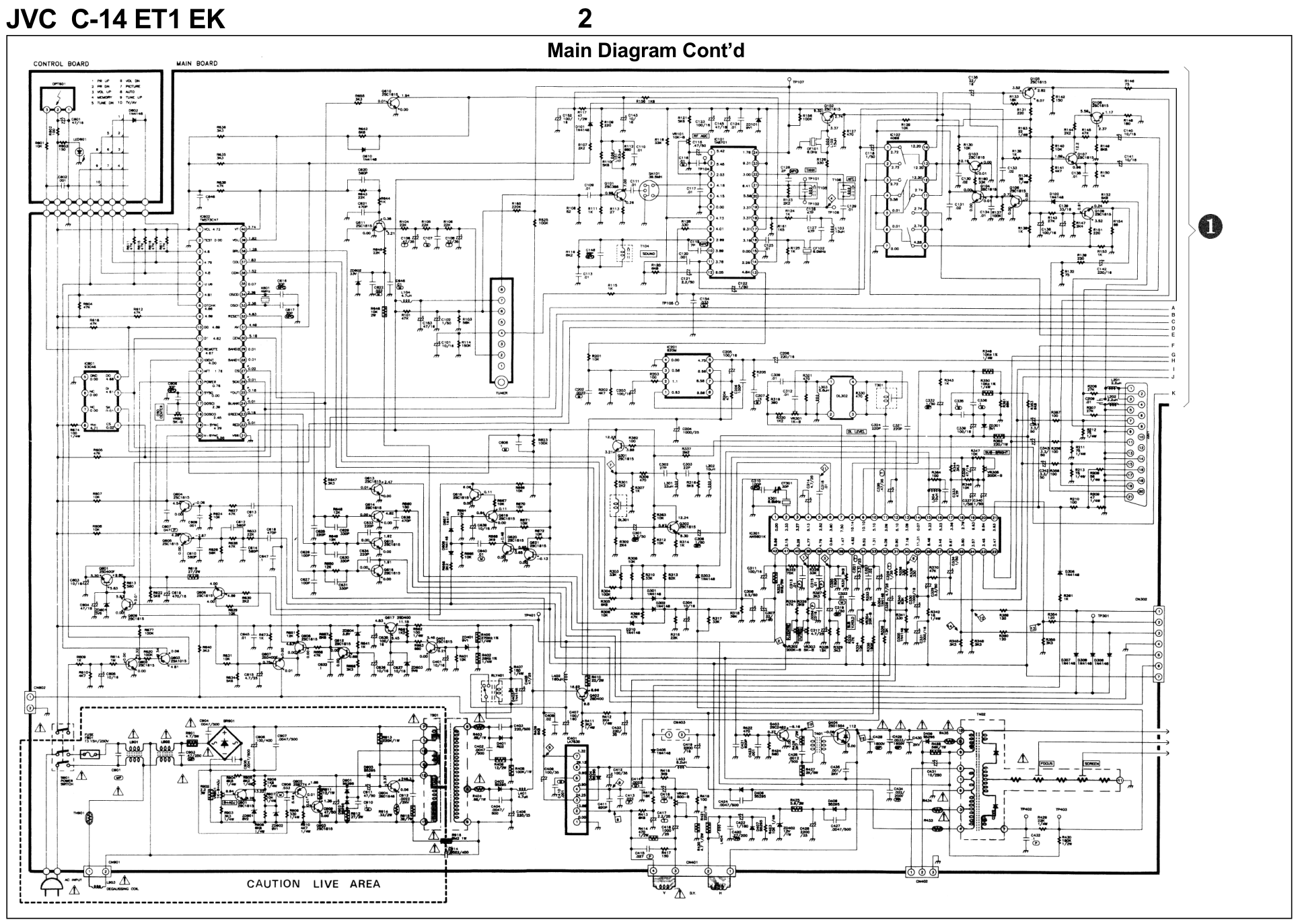
1 JVC C-14 ET1 EK Matrix Item See Model Book CRT Base .....................................................................................................C-14 E1 EK 5 Recommended Safety Parts Item Part No. Description Item Content Dimensions ............................................................... 360mm(W) x 334mm(H) x 378mm(D) Mass .......................................................................................................10.5kg (TV set only) TV System ...................................................................................................................... PAL I Teletext System .............................................................................................................FLOF Channel Coverage UHF band ...................................................................................................................... 21~ 69 Frequency Range UHF band ................................................................................................... 470MHz~ 862MHz Intermediate Frequency Video ......................................................................................................................... 39.5MHz Sound ........................................................................................................................ 33.5MHz Chroma ................................................................................................................... 35.07MHz Video/Sound Separation ...............................................................................................6MHz Antenna Input Impedance ......................................................................... 75Ω unbalanced Power Input .................................................................................................... 230V AC, 50Hz Power Consumption ....................................................................................................... 70W Picture Tube ......................................................................................... 14” (36cm) diagonal High Voltage ......................................................................... < 26kV (at zero beam current) Speaker ....................................................................................................... 5cm x 9cm (16Ω) Audio Output .......................................................................................................... 1W (max.) AV Connection ....................................................................................... 21 pin scart socket Specifications 12 046-100001-14A POWER SWITCH 27 102-314000-13 C.R.T. (ITC) (CAI.HONG) 37SX110Y22-DC05 29 108-400141-03 DEGAUSSING COIL ASSY L903 R403 013-688205-82 FP R 0.68Ω 1/2W 5% R404 013-688205-82 FP R 0.68Ω 1/2W 5% R433 013-688205-82 FP R 0.68Ω 1/2W 5% R434 013-688205-82 FP R 0.68Ω 1/2W 5% R435 013-688205-82 FP R 0.68Ω 1/2W 5% R901 013-479605-54 UNF R 4.7Ω 5W 5% R916 013-825305-92 HVR 8.2MΩ 1W 5% C428 026-332160-41 MPP CAP. 0.0033µF 1600V 5% C429 026-332160-41 MPP CAP. 0.0033µF 1600V 5% C430 026-222160-41 MP CAP. 0.0022µF 1600V 5% C901 026-224211-25 MF CAP. 0.22µF 250V 10% C902 026-474211-21C MP CAP. 0.47µF AC250V K C903 026-474211-21C MP CAP. 0.47µF AC250V K C914 123-222467-41 C CAP. 0.0022µF 400V M T402 101-214022-04 FLYBACK TRANSFORMER (FCK-14A028) T901 001-419220-94 SWITCHING TRANSFORMER L901 001-190013-95 CHOKE TRANSFORMER BR901 DS2BA RECTIFIER F901 082-223150-23 FUSE 3.15A L902 001-190004-95 LINE FILTER S901 046-100001-14A POWER SWITCH R501 013-129305-62 FPR 1.2Ω 1W 5% 061-540016-01 CRT SOCKET B+ ADJUSTMENT 1. Connect the digital volt meter to TP401. 2. Adjust semi-fixed resistor VR901 until meter reading DC 112 .25V ± 0.25V. HORIZONTAL CIRCUIT ADJUSTMENT 1. Receive colour bar or crosshatoh pattern. 2. IC301 (Pin 28, 29) short by 1K Ohm resistor. 3. Adjust VR303 to Obtain the picture running at center. 4.Remove the 1K Ohm resistor. COLOUR DEMODULATOR ADJUSTMENT, DELAY LINE ADJUSTMENT 1. Receive Philips Pattern. 2. Set Contrast control to minimum position. 3. Set Colour control to maximum position. 4. Connect Oscilloscope to TP301 (B-out). 5. Adjust CT301 to obtain the waveform as in Fig.1. 6. Adjust VR301 to obtain the waveform as in Fig 1. 7. Adjust T301 to obtain the waveform as in Fig 1. Fig. 1 VERTICAL CIRCUIT ADJUSTMENT 1. Receive the crosshatch pattern. 2. Connect the Frequency Counter between V- DEFLECTION YOKE connector and GND. 3. Connect the lead wire from TP106 to GND. 4. Adjust V-HOLD (VR304) to the reading 44Hz. (C-14 ET1 EK) 45Hz ± 0.5 Hz (C-14 E1 EK 5. Remove the lead wire from TP106 to GND. 6. Adjust V-SIZE (VR401) control to obtain a normal picture. WHITE BALANCE ADJUSTMENT 1. Receive a black and white picture signal. 2. Turn the red, green and blue CUT OFF (VR501, VR502, VR504) controls (in the CRT PW Board) to middle position and turn the DRIVE (VR503,VR505) controls (in the CRT PW Board) to middle position. 3. Turn the Screen control on the FBT to minimum position. 4. Set the SUB-BRIGHTNESS control (VR305) to middle position, then set the Contrast, Brightness and Colour control to minimum position. 5. CN403 (PIN 1 ,2) with join together. 6. Connect volt meter between R508 and ground, and adjust Brightness control to the reading of DC138V±2V. If DC138V can not be obtain, adjust the SUB-BRIGHTNESS control (VR305). 7. Slowly turn the Screen control clockwise to the point where a horizontal line just illumi- nates. 8. Adjust VR501 to get a red horizontal line on CRT. 9. Adjust VR502 to get a yellow horizontal line on CRT. 10.Adjust VR504 to get a white horizontal line on CRT. 11.Take the joiner Out of CN403. Service Adjustments Remote Handset Diagram 12.Adjust DRIVE (VR503, VR505) controls to obtain a uniform white picture. FOCUS ADJUSTMENT 1. Set Contrast control to maximum position and Brightness control to middle position. 2. Adjust Focus control (on the FBT) to obtain a sharpest and clearest picture on the CRT. RF AGC ADJUSTMENT 1. Receive a broadcast. 2. Turn the RF AGC VR (VR101) so that noise appears on the screen. 3. Turn the RF AGC VR (VR101) until the noise disappears. 4. Change the channel and check that the picture is normal. SUB-BRIGHTNESS ADJUSTMENT Check the white balance is adjusted. 1. Receive an entirely black signal. 2. Adjust the SUB-BRIGHTNESS VR (VR305) until the entirely picture lights. ON SCREEN POSITION ADJUSTMENT 1. Receive the crosshatch pattern. 2. Display the on-screen character. Adjust the ON-SCREEN (VR601) so that the on-screen position becomes center. TELETEXT PICTURE ADJUSTMENT 1. Receive a pattern with teletext signal. 2. Select a teletext page. 3. Connect DC voltage meter to TP303 (IC001 PIN 28) and GND. 4. Adjust Tool to obtain DC 2.5V ± 0.05V. Main Diagram 2 JVC C-14 ET1 EK Main Diagram Cont’d
版权声明
1. 本站所有素材,仅限学习交流,仅展示部分内容,如需查看完整内容,请下载原文件。
2. 会员在本站下载的所有素材,只拥有使用权,著作权归原作者所有。
3. 所有素材,未经合法授权,请勿用于商业用途,会员不得以任何形式发布、传播、复制、转售该素材,否则一律封号处理。
4. 如果素材损害你的权益请联系客服QQ:77594475 处理。