东芝2163DB彩电电路原理图
 "东芝2163DB彩电电路原理图-0")
 "东芝2163DB彩电电路原理图-1")
 "东芝2163DB彩电电路原理图-2")
 "东芝2163DB彩电电路原理图-3")
 "东芝2163DB彩电电路原理图-4")
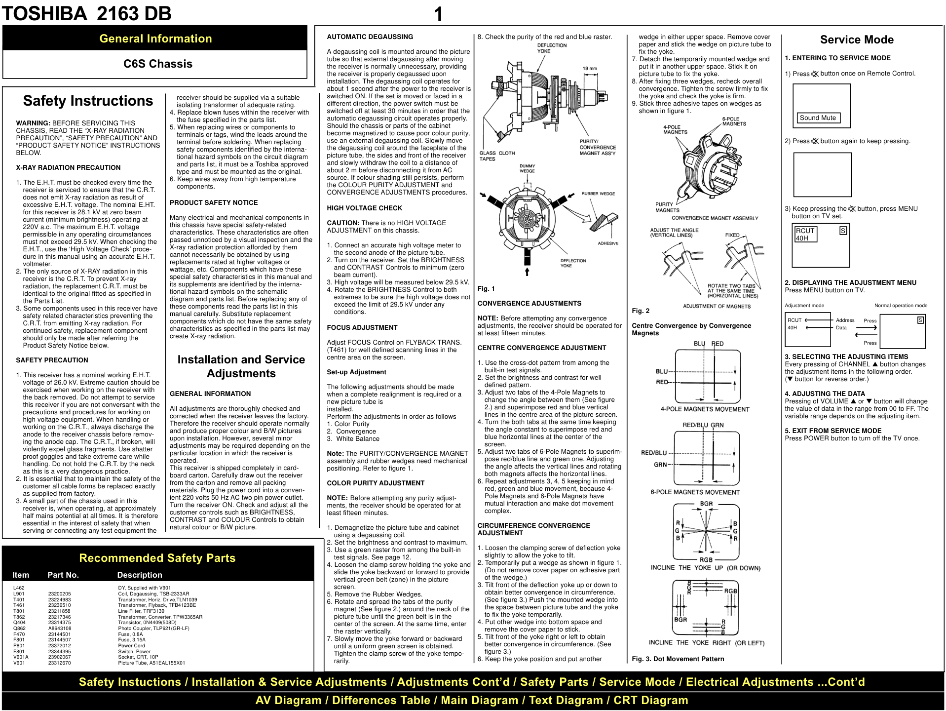
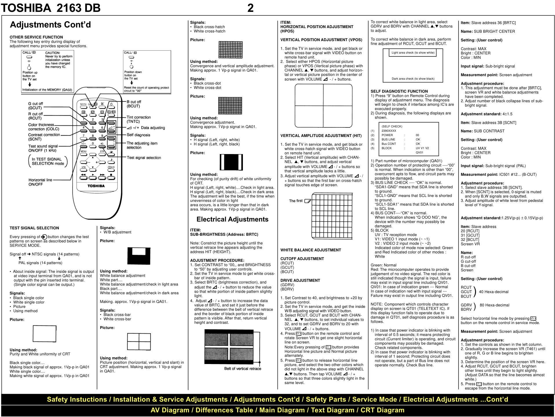
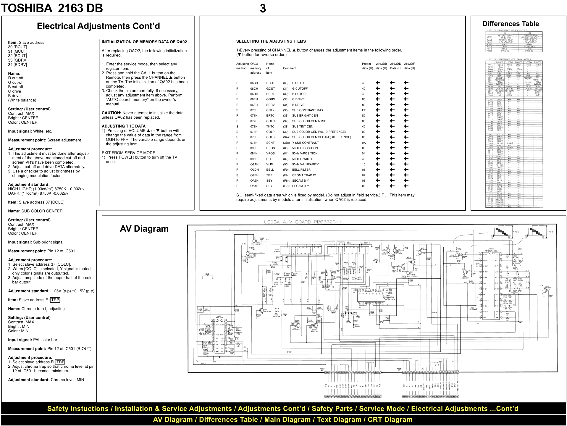
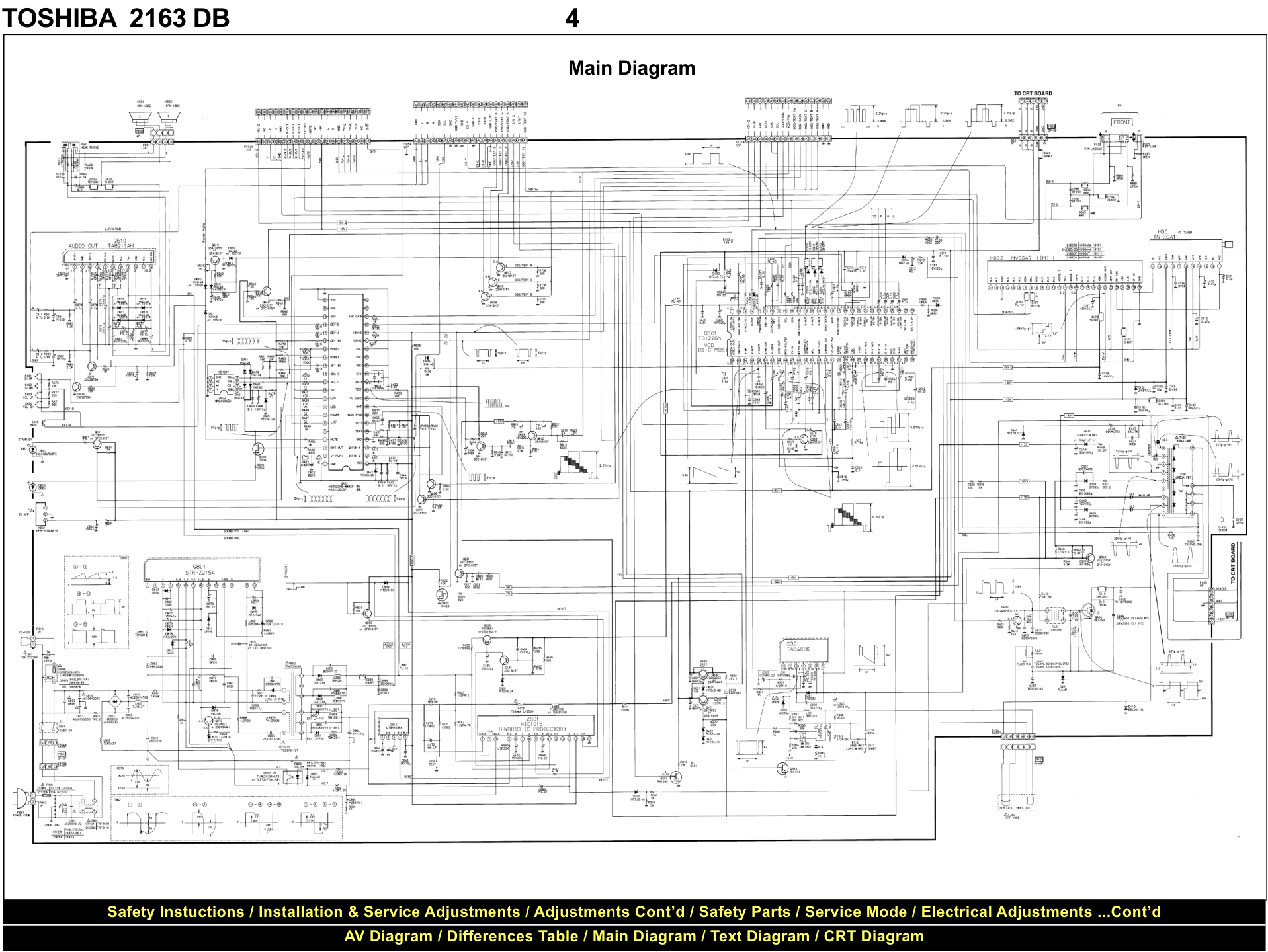
1 TOSHIBA 2163 DB Safety Instuctions / Installation & Service Adjustments / Adjustments Cont’d / Safety Parts / Service Mode / Electrical Adjustments ...Cont’d AV Diagram / Differences Table / Main Diagram / Text Diagram / CRT Diagram General Information C6S Chassis Recommended Safety Parts Item Part No. Description L462 DY, Supplied with V901 L901 23200205 Coil, Degaussing, TSB-2333AR T401 23224983 Transformer, Horiz. Drive,TLN1039 T461 23236510 Transformer, Flyback, TFB4123BE T801 23211858 Line Filter, TRF3139 T862 23217346 Transformer, Converter, TPW3365AR Q404 23314375 Transistor, 0N4409(508D) Q862 A8643108 Photo Coupler, TLP621(GR-LF) F470 23144501 Fuse, 0.8A F801 23144507 Fuse, 3.15A P801 23372012 Power Cord F801 23344395 Switch, Power V901A 23902067 Socket, CRT, 10P V901 23312670 Picture Tube, A51EAL155X01 Safety Instructions WARNING: BEFORE SERVICING THIS CHASSIS, READ THE “X-RAY RADIATION PRECAUTION”, “SAFETY PRECAUTION” AND “PRODUCT SAFETY NOTICE” INSTRUCTIONS BELOW. X-RAY RADIATION PRECAUTION 1. The E.H.T. must be checked every time the receiver is serviced to ensure that the C.R.T. does not emit X-ray radiation as result of excessive E.H.T. voltage. The nominal E.HT. for this receiver is 28.1 kV at zero beam current (minimum brightness) operating at 220V a.c. The maximum E.H.T. voltage permissible in any operating circumstances must not exceed 29.5 kV. When checking the E.H.T., use the ‘High Voltage Check’ proce- dure in this manual using an accurate E.H.T. voltmeter. 2. The only source of X-RAY radiation in this receiver is the C.R.T. To prevent X-ray radiation, the replacement C.R.T. must be identical to the original fitted as specified in the Parts List. 3. Some components used in this receiver have safety related characteristics preventing the C.R.T. from emitting X-ray radiation. For continued safety, replacement component should only be made after referring the Product Safety Notice below. SAFETY PRECAUTION 1. This receiver has a nominal working E.H.T. voltage of 26.0 kV. Extreme caution should be exercised when working on the receiver with the back removed. Do not attempt to service this receiver if you are not conversant with the precautions and procedures for working on high voltage equipment. When handling or working on the C.R.T., always discharge the anode to the receiver chassis before remov- ing the anode cap. The C.R.T., if broken, will violently expel glass fragments. Use shatter proof goggles and take extreme care while handling. Do not hold the C.R.T. by the neck as this is a very dangerous practice. 2. It is essential that to maintain the safety of the customer all cable forms be replaced exactly as supplied from factory. 3. A small part of the chassis used in this receiver is, when operating, at approximately half mains potential at all times. It is therefore essential in the interest of safety that when serving or connecting any test equipment the receiver should be supplied via a suitable isolating transformer of adequate rating. 4. Replace blown fuses within the receiver with the fuse specified in the parts list. 5. When replacing wires or components to terminals or tags, wind the leads around the terminal before soldering. When replacing safety components identified by the interna- tional hazard symbols on the circuit diagram and parts list, it must be a Toshiba approved type and must be mounted as the original. 6. Keep wires away from high temperature components. PRODUCT SAFETY NOTICE Many electrical and mechanical components in this chassis have special safety-related characteristics. These characteristics are often passed unnoticed by a visual inspection and the X-ray radiation protection afforded by them cannot necessarily be obtained by using replacements rated at higher voltages or wattage, etc. Components which have these special safety characteristics in this manual and its supplements are identified by the interna- tional hazard symbols on the schematic diagram and parts list. Before replacing any of these components read the parts list in this manual carefully. Substitute replacement components which do not have the same safety characteristics as specified in the parts list may create X-ray radiation. Installation and Service Adjustments GENERAL INFORMATION All adjustments are thoroughly checked and corrected when the receiver leaves the factory. Therefore the receiver should operate normally and produce proper colour and B/W pictures upon installation. However, several minor adjustments may be required depending on the particular location in which the receiver is operated. This receiver is shipped completely in card- board carton. Carefully draw out the receiver from the carton and remove all packing materials. Plug the power cord into a conven- ient 220 volts 50 Hz AC two pin power outlet. Turn the receiver ON. Check and adjust all the customer controls such as BRIGHTNESS, CONTRAST and COLOUR Controls to obtain natural colour or B/W picture. AUTOMATIC DEGAUSSING A degaussing coil is mounted around the picture tube so that external degaussing after moving the receiver is normally unnecessary, providing the receiver is properly degaussed upon installation. The degaussing coil operates for about 1 second after the power to the receiver is switched ON. If the set is moved or faced in a different direction, the power switch must be switched off at least 30 minutes in order that the automatic degaussing circuit operates properly. Should the chassis or parts of the cabinet become magnetized to cause poor colour purity, use an external degaussing coil. Slowly move the degaussing coil around the faceplate of the picture tube, the sides and front of the receiver and slowly withdraw the coil to a distance of about 2 m before disconnecting it from AC source. If colour shading still persists, perform the COLOUR PURITY ADJUSTMENT and CONVERGENCE ADJUSTMENTS procedures. HIGH VOLTAGE CHECK CAUTION: There is no HIGH VOLTAGE ADJUSTMENT on this chassis. 1. Connect an accurate high voltage meter to the second anode of the picture tube. 2. Turn on the receiver. Set the BRIGHTNESS and CONTRAST Controls to minimum (zero beam current). 3. High voltage will be measured below 29.5 kV. 4. Rotate the BRIGHTNESS Control to both extremes to be sure the high voltage does not exceed the limit of 29.5 kV under any conditions. FOCUS ADJUSTMENT Adjust FOCUS Control on FLYBACK TRANS. (T461) for well defined scanning lines in the centre area on the screen. Set-up Adjustment The following adjustments should be made when a complete realignment is required or a new picture tube is installed. Perform the adjustments in order as follows 1. Color Purity 2. Convergence 3. White Balance Note: The PURITY/CONVERGENCE MAGNET assembly and rubber wedges need mechanical positioning. Refer to figure 1. COLOR PURITY ADJUSTMENT NOTE: Before attempting any purity adjust- ments, the receiver should be operated for at least fifteen minutes. 1. Demagnetize the picture tube and cabinet using a degaussing coil. 2. Set the brightness and contrast to maximum. 3. Use a green raster from among the built-in test signals. See page 12. 4. Loosen the clamp screw holding the yoke and slide the yoke backward or forward to provide vertical green belt (zone) in the picture screen. 5. Remove the Rubber Wedges. 6. Rotate and spread the tabs of the purity magnet (See figure 2.) around the neck of the picture tube until the green belt is in the center of the screen. At the same time, enter the raster vertically. 7. Slowly move the yoke forward or backward until a uniform green screen is obtained. Tighten the clamp screw of the yoke tempo- rarily. 8. Check the purity of the red and blue raster. Fig. 1 CONVERGENCE ADJUSTMENTS NOTE: Before attempting any convergence adjustments, the receiver should be operated for at least fifteen minutes. CENTRE CONVERGENCE ADJUSTMENT 1. Use the cross-dot pattern from among the built-in test signals. 2. Set the brightness and contrast for well defined pattern. 3. Adjust two tabs of the 4-Pole Magnets to change the angle between them (See figure 2.) and superimpose red and blue vertical lines in the centre area of the picture screen. 4. Turn the both tabs at the same time keeping the angle constant to superimpose red and blue horizontal lines at the center of the screen. 5. Adjust two tabs of 6-Pole Magnets to superim- pose red/blue line and green one. Adjusting the angle affects the vertical lines and rotating both magnets affects the horizontal lines. 6. Repeat adjustments 3, 4, 5 keeping in mind red, green and blue movement, because 4- Pole Magnets and 6-Pole Magnets have mutual interaction and make dot movement complex. CIRCUMFERENCE CONVERGENCE ADJUSTMENT 1. Loosen the clamping screw of deflection yoke slightly to allow the yoke to tilt. 2. Temporarily put a wedge as shown in figure 1. (Do not remove cover paper on adhesive part of the wedge.) 3. Tilt front of the deflection yoke up or down to obtain better convergence in circumference. (See figure 3.) Push the mounted wedge into the space between picture tube and the yoke to fix the yoke temporarily. 4. Put other wedge into bottom space and remove the cover paper to stick. 5. Tilt front of the yoke right or left to obtain better convergence in circumference. (See figure 3.) 6. Keep the yoke position and put another wedge in either upper space. Remove cover paper and stick the wedge on picture tube to fix the yoke. 7. Detach the temporarily mounted wedge and put it in another upper space. Stick it on picture tube to fix the yoke. 8. After fixing three wedges, recheck overall convergence. Tighten the screw firmly to fix the yoke and check the yoke is firm. 9. Stick three adhesive tapes on wedges as shown in figure 1. Fig. 2 Centre Convergence by Convergence Magnets Fig. 3. Dot Movement Pattern Service Mode 1. ENTERING TO SERVICE MODE 1) Press button once on Remote Control. Sound Mute 2) Press button again to keep pressing. 3) Keep pressing the button, press MENU button on TV set. RCUT S 40H 2. DISPLAYING THE ADJUSTMENT MENU Press MENU button on TV. Adjustment mode Normal operation mode RCUT Address S 40H Data 3. SELECTING THE ADJUSTING ITEMS Every pressing of CHANNEL L button changes the adjustment items in the following order. (M button for reverse order.) 4. ADJUSTING THE DATA Pressing of VOLUME L or M button will change the value of data in the range from 00 to FF. The variable range depends on the adjusting item. 5. EXIT FROM SERVICE MODE Press POWER button to turn off the TV once. Press Press 2 TOSHIBA 2163 DB Safety Instuctions / Installation & Service Adjustments / Adjustments Cont’d / Safety Parts / Service Mode / Electrical Adjustments ...Cont’d AV Diagram / Differences Table / Main Diagram / Text Diagram / CRT Diagram OTHER SERVICE FUNCTION The following key entry during display of adjustment menu provides special functions. TEST SIGNAL SELECTION Every pressing of button changes the test patterns on screen as described below in SERVICE MODE. Signal off ➜ NTSC signals (14 patterns) PAL signals (14 patterns) • About inside signal: The inside signal is output at video input terminal from QA01, and is not output with the pin inserted into terminal. (Single color signal can be output.) Signals: • Black single color • White single color • Picture • Using method Picture: Using method: Purity and White uniformity of CRT Black single color.... Making black signal of approx. 1Vp-p in QA01 White single color.... Making white signal of approx. 1Vp-p in QA01 Signals: • W/B adjustment Picture: Using method: White balance adjustment White part.... White balance adjustment/check in light area Black part.... White balance adjustment/check in dark area Making. approx. 1Vp-p signal in QA01. Signals: • Black cross-bar • White cross-bar Picture: Using method: Picture position (horizontal, vertical and slant) in CRT adjustment. Making approx. 1 Vp-p signal in QA01. Signals: • Black cross-hatch • White cross-hatch Picture: Using method: Convergence and vertical amplitude adjustment. Making approx. 1 Vp-p signal in QA01. Signals: • Black cross-dot • White cross-dot Picture: Using method: Convergence adjustment. Making approx. 1Vp-p signal in QA01. Signals: • H signal (Left, right, white) • H signal (Left, right, black) Picture: Using method: For checking (of purity drift) of white uniformity of CRT. H signal (Left, right, white)....Check in light area. H signal (Left, right, black)....Check in dark area The adjustment will be the best, if the time when unevenness of color in light area occurs, is a little longer than that in dark area. Making approx. 1Vp-p signal in QA01. Electrical Adjustments ITEM: SUB-BRIGHTNESS (Address: BRTC) Note: Constrict the picture height until the vertical retrace line appears adjusting the address HIT (HEIGHT). ADJUSTMENT PROCEDURE: 1. Set CONTRAST to “00,, and BRIGHTNESS to “50” by adjusting user controls. 2. Set the TV in service mode to get white cross- bar of inside pattern. 3. Select BRTC (brightness correction), and adjust the - / + button to reduce the value so that white portion of inside pattern slightly light. 4. Adjust - / + button to increase the data value of BRTC, and set it just before the difference between the belt of vertical retrace and the border of black portion of inside pattern is visible. After that, return vertical height and contrast. ITEM: HORIZONTAL POSITION ADJUSTMENT (HPOS) VERTICAL POSITION ADJUSTMENT (VPOS) 1. Set the TV in service mode, and get black or white cross-bar signal with VIDEO button on remote hand unit. 2. Select either HPOS (Horizontal picture phase) or VPOS (Vertical picture phase) with CHANNEL L, M buttons, and adjust horizon- tal or vertical picture position in the center of screen with VOLUME - / + buttons. VERTICAL AMPLITUDE ADJUSTMENT (HIT) 1. Set the TV in service mode, and get black or white cross-hatch signal with VIDEO button on remote hand unit. 2. Select HIT (Vertical amplitude) with CHAN- NEL L, M buttons, and adjust vertical amplitude with VOLUME - / + buttons so that vertical amplitude lacks a little. 3. Adjust vertical amplitude with VOLUME - / + buttons so that the first bar on cross-hatch signal touches edge of screen. WHITE BALANCE ADJUSTMENT CUTOFF ADJUSTMENT (RCUT) (GCUT) (BCUT) DRIVE ADJUSTMENT (GDRV) (BDRV) 1. Set Contrast to 40, and brightness to +20 by picture control. 2. Set the TV in service mode, and get the inside W/B adjusting signal with VIDEO button. 3. Select RCUT, GCUT and BCUT with CHAN- NEL L, M buttons, to set individual values to 32, and to set GDRV and BDRV to 20 with VOLUME - / + buttons. 4. Press button on the remote control and rotate Screen VR to get one slight horizontal line on screen. Note:Every pressing of button provides Horizontal line picture and Normal picture alternately. 5. Press button to release horizontal line picture, and select the two other colors which did not light in the above step with CHANNEL L,M buttons. Then tap VOLUME - / + buttons so that three colors slightly light in the same level. To correct white balance in light area, select GDRV and BDRV with CHANNEL L,M buttons to adjust. To correct white balance in dark area, perform fine adjustment of RCUT, GCUT and BCUT. Light area check (to show white) Dark area check (to show black) SELF DIAGNOSTIC FUNCTION 1) Press “9” button on Remote Control during display of adjustment menu. The diagnosis will begin to check if interface among IC’s are executed properly. 2) During diagnosis, the following displays are shown. (SELF CHECK) (1) 2390XXXX (2) POWER : 00 (3) BUS LINE : OK (4) Bus CONT : OK (5) BLOCK : UV V1 V2 QV01 1) Part number of microcomputer (QA01) 2) Operation number of protecting circuit ----“00” is normal. When indication is other than “00”, overcurrent apts to flow, and circuit parts may possibly be damaged. 3) BUS LINE CHECK ---- “OK” is normal. “SDA1-GND” means that SDA line is shorted to ground. “SCL1-GND” means that SCL line is shorted to ground. “SCL1-SDA1” means that SDA line is shorted to SCL line. 4) BUS CONT----“OK” is normal. When indication shows “Q OOO NG”, the device with the number may possibly be damaged. 5) BLOCK UV : TV reception mode V1: VIDEO 1 input mode (~ ~1) V2 : VIDEO 2 input mode (~ ~2) Indicated color of mode now selected: Green and Red Indicated color of other modes : White Green: Normal Red: The microcomputer operates to provide judgement of no video signal. The red color is still indicated though the signal is input, failure may exist in input signal line including QV01. QV01: In case of indication green --- Normal In case of indication red with input signal --- Failure may exist in output line including QV01. NOTE: Component which controls character display on screen is QT01 (TELETEXT IC). If this display function fails to operate due to damage in QT01, self diagnosis procedure is as follows. 1) In case that power indicator is blinking with interval of 0.5 seconds; it means protecting circuit (Current limiter) is operating, and circuit components may possibly be damaged. Check related components. 2) In case that power indicator is blinking with interval of 1 second; Protecting circuit does not operate, but a part of Bus line does not operate normally. Check Bus line. Item: Slave address 36 [BRTC] Name: SUB BRIGHT CENTER Setting: (User control) Contrast: MAX Bright : CENTER Color : MIN Input signal: Sub-bright signal Measurement point: Screen adjustment Adjustment procedure: 1. This adjustment must be done after [BRTC], screen VR and white balance adjustments have been completed. 2. Adjust number of black collapse lines of sub- bright signal. Adjustment standard: 4±1.5 Item: Slave address 3B [SCNT] Name: SUB CONTRAST Setting: (User control) Contrast: MAX Bright : CENTER Color : MIN Input signal: Sub-bright signal (PAL) Measurement point: IC501 #12... (B-OUT) Adjustment procedure: 1. Select slave address 3B [SCNT]. 2. When [SCNT] is selected, 0-signal is muted and only B,W signals are outputted. 3. Adjust amplitude of white level from pedestal level of Y-signal. Adjustment standard:1.25V(p-p) ± 0.15V(p-p) Item: Slave address 20 [RCUT] 31 [GCUT] 32 [BCUT] Screen VR Name: R cut-off G cut-off B cut-off Screen Setting: (User control) RCUT GCUT 40 Hexa-decimal BCUT GDRV 80 Hexa-decimal BDRV Select horizontal line mode by pressing button on the remote control in service mode. Measurement point: Screen adjustment Adjustment procedure: 1. Set the controls as shown in the left column. 2. Gradually increase the screen VR (T461) until one of R, G or B line begins to brighten slightly. 3. Determine the position of the screen VR here. 4. Adjust RCUT, GCUT and BCUT, brighten other lines until they begin to light slightly. (Adjust DATA so that the line becomes almost white.) 5. Press button on the remote control to escape from the horizontal line mode. Adjustments Cont’d ➜ ➜ ➜ ) ) 3 TOSHIBA 2163 DB Safety Instuctions / Installation & Service Adjustments / Adjustments Cont’d / Safety Parts / Service Mode / Electrical Adjustments ...Cont’d AV Diagram / Differences Table / Main Diagram / Text Diagram / CRT Diagram Item: Slave address 30 [RCUT] 31 [GCUT] 32 [BCUT] 33 [GDRV] 34 [BDRV] Name: R cut-off G cut-off B cut-off G drive B drive (White balance) Setting: (User control) Contrast: MAX Bright : CENTER Color : CENTER Input signal: White, etc. Measurement point: Screen adjustment Adjustment procedure: 1. This adjustment must be done after adjust- ment of the above-mentioned cut-off and screen VR’s have been completed. 2. Adjust cut-off and drive DATA alternately. 3. Use a checker to adjust brightness by changing modulation factor. Adjustment standard: HIGH LIGHT; (1 03cd/m3) 8750K—0.002uv DARK; (17cd/m3) 8750K -0.002uv Item: Slave address 37 [COLC] Name: SUB COLOR CENTER Setting: (User control) Contrast: MAX Bright : CENTER Color : CENTER Input signal: Sub-bright signal Measurement point: Pin 12 of IC501 Adjustment procedure: 1. Select slave address 37 [COLC]. 2. When [COLC] is selected, Y signal is muted only color signals are outputted. 3. Adjust amplitude of the upper half of the-color bar output. Adjustment standard: 1.25V (p-p) ±0.15V (p-p) Item: Slave address F1 TRP Name: Chroma trap f0 adjusting Setting: (User control) Contrast: MAX Bright : MIN Color : MIN Input signal: PAL color bar Measurement point: Pin 12 of IC501 (B-OUT) Adjustment procedure: 1. Select slave address Fl TRP 2. Adjust chroma trap so that chroma level at pin 12 of IC501 becomes minimum. Adjustment standard: Chroma level: MIN SELECTING THE ADJUSTING ITEMS 1)Every pressing of CHANNEL L button changes the adjustment items in the following order. (M button for reverse order.) Adjusting QA02 Name Preset 2163DB 2163DD 2163DF method memory of Comment data (H) data (H) Data (H) data (H) address item F 06BH RCUT (30): R CUTOFF 40 F 06CH GCUT (31): G CUTOFF 40 F 06DH BCUT (32): B CUTOFF 40 F 06EH GDRV (33): G DRIVE 80 F 06FH BDRV (34): B DRIVE 80 S 070H CNTX (35): SUB CONTRAST MAX FF F 071H BRTC (36): SUB BRIGHT CEN 80 F 072H COLC (37): SUB COLOR CEN NTSC 80 S 073H TNTC (38): SUB TINT CEN 40 S 074H COLP (39): SUB COLOR CEN PAL (DIFFERENCE) 00 S 075H COLS (3A): SUB COLOR CEN SECAM (DIFFERENCE) 00 F 076H SCNT (3B): Y-SUB CONTRAST 0A F 093H HPOS (80): 50Hz H-POSITION 05 F 094H VPOS (81): 50Hz V-POSITION 04 F 095H HIT (82) : 50Hz H-WIDTH 40 F O9AH VLIN (90) : 50Hz V-LINEARITY 10 F O9DH BELL (F0) : BELL FILTER 01 S O9EH TRP (Fl): CROMA TRAP fO 02 F OA3H SBY (F6): SECAM B-Y 08 F OA4H SRY (F7): SECAM R-Y 08 S ... semi-fixed data area which is fixed by model. (Do not adjust in field service.) F ... This item may require adjustments by models after initialization, when QA02 is replaced. INITIALIZATION OF MEMORY DATA OF QA02 After replacing QAO2, the following initialization is required. 1. Enter the service mode, then select any register item. 2. Press and hold the CALL button on the Remote, then press the CHANNEL L button on the TV. The initialization of QA02 has been completed. 3. Check the picture carefully. If necessary, adjust any adjustment item above. Perform “AUTO search memory” on the owner’s manual. CAUTION: Never attempt to initialize the data unless QA02 has been replaced. ADJUSTING THE DATA 1) Pressing of VOLUME L or M button will change the value of data in the range from OGH to FFH. The variable range depends on the adjusting item. EXIT FROM SERVICE MODE 1) Press POWER button to turn off the TV once. Electrical Adjustments Cont’d AV Diagram Differences Table 4 TOSHIBA 2163 DB Safety Instuctions / Installation & Service Adjustments / Adjustments Cont’d / Safety Parts / Service Mode / Electrical Adjustments ...Cont’d AV Diagram / Differences Table / Main Diagram / Text Diagram / CRT Diagram Main Diagram 5 TOSHIBA 2163 DB Safety Instuctions / Installation & Service Adjustments / Adjustments Cont’d / Safety Parts / Service Mode / Electrical Adjustments ...Cont’d AV Diagram / Differences Table / Main Diagram / Text Diagram / CRT Diagram Text Diagram CRT Diagram
版权声明
1. 本站所有素材,仅限学习交流,仅展示部分内容,如需查看完整内容,请下载原文件。
2. 会员在本站下载的所有素材,只拥有使用权,著作权归原作者所有。
3. 所有素材,未经合法授权,请勿用于商业用途,会员不得以任何形式发布、传播、复制、转售该素材,否则一律封号处理。
4. 如果素材损害你的权益请联系客服QQ:77594475 处理。