马兰士MARANTZ DV3100N1B音响电路图
 "马兰士MARANTZ DV3100N1B音响电路图-0")
 "马兰士MARANTZ DV3100N1B音响电路图-1")
 "马兰士MARANTZ DV3100N1B音响电路图-2")
 "马兰士MARANTZ DV3100N1B音响电路图-3")
 "马兰士MARANTZ DV3100N1B音响电路图-4")
 "马兰士MARANTZ DV3100N1B音响电路图-5")
 "马兰士MARANTZ DV3100N1B音响电路图-6")
 "马兰士MARANTZ DV3100N1B音响电路图-7")
 "马兰士MARANTZ DV3100N1B音响电路图-8")
 "马兰士MARANTZ DV3100N1B音响电路图-9")
DVD Player
TABLE OF CONTENTS
SECTION
PAGE
1. TECHNICAL SPECIFICATIONS ................................................................................................................ 1
2. PRODUCT SAFETY SERVICING GUIDELINE FOR VIDEO PRODUCTS ................................................ 2
/SERVICING PRECAUTIONS .................................................................................................................... 3
3. INFORMATIONS ........................................................................................................................................ 4
4. SERVICING HINT....................................................................................................................................... 5
5. REGIONAL CODES ................................................................................................................................... 6
6. LOCATION OF CUSTOMER CONTROLS ................................................................................................. 7
7. DISASSEMBLY ....................................................................................................................................... 2-2
8. EXPLODED VIEWS/PARTS LIST ........................................................................................................... 2-4
9. ELECTRICAL TROUBLESHOOTING GUIDE ......................................................................................... 3-2
10. BLOCK DIAGRAMS .............................................................................................................................. 3-12
11. CIRCUIT DIAGRAMS ............................................................................................................................ 3-18
12. PRINTED CIRCUIT DIAGRAMS/ELECTRICAL PARTS LIST .............................................................. 3-38
13. DECK MECHANISM ................................................................................................................................ 4-1
Service
Manual
DV3100 /N1B
Please use this service manual with referring to the user guide (D.F.U) without fail.
R
DV3100
304W855020 ACT
3120 785 22450
First Issue:2000.10
DVD PLAYER DV3100
STANDBY
STANDBY/ON
POWER
OPEN/CLOSE
STOP
PAUSE
PLAY
DV3100
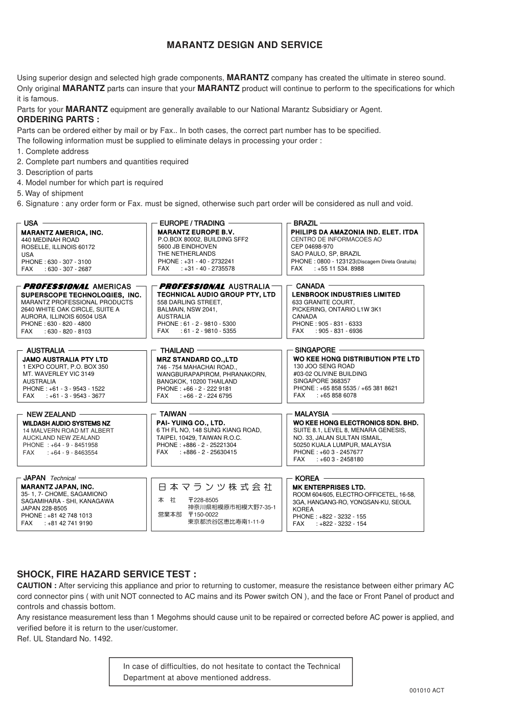
MARANTZ DESIGN AND SERVICE
Using superior design and selected high grade components, MARANTZ company has created the ultimate in stereo sound.
Only original MARANTZ parts can insure that your MARANTZ product will continue to perform to the specifications for which
it is famous.
Parts for your MARANTZ equipment are generally available to our National Marantz Subsidiary or Agent.
ORDERING PARTS :
Parts can be ordered either by mail or by Fax.. In both cases, the correct part number has to be specified.
The following information must be supplied to eliminate delays in processing your order :
1. Complete address
2. Complete part numbers and quantities required
3. Description of parts
4. Model number for which part is required
5. Way of shipment
6. Signature : any order form or Fax. must be signed, otherwise such part order will be considered as null and void.
SHOCK, FIRE HAZARD SERVICE TEST :
CAUTION : After servicing this appliance and prior to returning to customer, measure the resistance between either primary AC
cord connector pins ( with unit NOT connected to AC mains and its Power switch ON ), and the face or Front Panel of product and
controls and chassis bottom.
Any resistance measurement less than 1 Megohms should cause unit to be repaired or corrected before AC power is applied, and
verified before it is return to the user/customer.
Ref. UL Standard No. 1492.
In case of difficulties, do not hesitate to contact the Technical
Department at above mentioned address.
001010 ACT
USA
MARANTZ AMERICA, INC
MARANTZ AMERICA, INC.
440 MEDINAH ROAD
ROSELLE, ILLINOIS 60172
USA
PHONE : 630 - 307 - 3100
FAX : 630 - 307 - 2687
BRAZIL
PHILIPS DA AMAZONIA IND. ELET. ITDA
CENTRO DE INFORMACOES AO
CEP 04698-970
SAO PAULO, SP, BRAZIL
PHONE : 0800 - 123123(Discagem Direta Gratuita)
FAX : +55 11 534. 8988
JAPAN Technical
MARANTZ JAPAN, INC.
35- 1, 7- CHOME, SAGAMIONO
SAGAMIHARA - SHI, KANAGAWA
JAPAN 228-8505
PHONE : +81 42 748 1013
FAX : +81 42 741 9190
EUROPE / TRADING
MARANTZ EUROPE B.V.
P.O.BOX 80002, BUILDING SFF2
5600 JB EINDHOVEN
THE NETHERLANDS
PHONE : +31 - 40 - 2732241
FAX : +31 - 40 - 2735578
TECHNICAL AUDIO GROUP PTY, LTD
558 DARLING STREET,
BALMAIN, NSW 2041,
AUSTRALIA
PHONE : 61 - 2 - 9810 - 5300
FAX : 61 - 2 - 9810 - 5355
CANADA
LENBROOK INDUSTRIES LIMITED
633 GRANITE COURT,
PICKERING, ONTARIO L1W 3K1
CANADA
PHONE : 905 - 831 - 6333
FAX : 905 - 831 - 6936
AUSTRALIA
JAMO AUSTRALIA PTY LTD
1 EXPO COURT, P.O. BOX 350
MT. WAVERLEY VIC 3149
AUSTRALIA
PHONE : +61 - 3 - 9543 - 1522
FAX : +61 - 3 - 9543 - 3677
NEW ZEALAND
WILDASH AUDIO SYSTEMS NZ
14 MALVERN ROAD MT ALBERT
AUCKLAND NEW ZEALAND
PHONE : +64 - 9 - 8451958
FAX
: +64 - 9 - 8463554
THAILAND
MRZ STANDARD CO.,LTD
746 - 754 MAHACHAI ROAD.,
WANGBURAPAPIROM, PHRANAKORN,
BANGKOK, 10200 THAILAND
PHONE : +66 - 2 - 222 9181
FAX : +66 - 2 - 224 6795
TAIWAN
PAI- YUING CO., LTD.
6 TH FL NO, 148 SUNG KIANG ROAD,
TAIPEI, 10429, TAIWAN R.O.C.
PHONE : +886 - 2 - 25221304
FAX : +886 - 2 - 25630415
MALAYSIA
WO KEE HONG ELECTRONICS SDN. BHD.
SUITE 8.1, LEVEL 8, MENARA GENESIS,
NO. 33, JALAN SULTAN ISMAIL,
50250 KUALA LUMPUR, MALAYSIA
PHONE : +60 3 - 2457677
FAX : +60 3 - 2458180
AMERICAS
SUPERSCOPE TECHNOLOGIES, INC.
MARANTZ PROFESSIONAL PRODUCTS
2640 WHITE OAK CIRCLE, SUITE A
AURORA, ILLINOIS 60504 USA
PHONE : 630 - 820 - 4800
FAX : 630 - 820 - 8103
AUSTRALIA
KOREA
MK ENTERPRISES LTD.
ROOM 604/605, ELECTRO-OFFICETEL, 16-58,
3GA, HANGANG-RO, YONGSAN-KU, SEOUL
KOREA
PHONE : +822 - 3232 - 155
FAX : +822 - 3232 - 154
SINGAPORE
WO KEE HONG DISTRIBUTION PTE LTD
130 JOO SENG ROAD
#03-02 OLIVINE BUILDING
SINGAPORE 368357
PHONE : +65 858 5535 / +65 381 8621
FAX : +65 858 6078
1
TECHNICAL SPECIFICATIONS
DVD VIDEO PLAYER
Power supply
AC 120V, 60Hz(U1B)
/AC100V, 50/60Hz(F1N)
/AC220~240V, 50Hz(N1B)
/110~240V, 50Hz(K1G, A1B)
Power consumption
16W
Mass
3.2kg(7.1lbs)
External dimensions
430 x 88 x 215 (W x H x D)
Signal system
NTSC 525/60, PAL 625/50
Laser
Semiconductor laser, wavelength 650nm
Frequency range (audio)
4Hz to 20 kHz
Signal-to-noise ratio (audio)
More than 100 dB (EIAJ)
Dynamic range (audio)
More than 95 dB (EIAJ)
Harmonic distortion(audio)
0.008%
Wow and flutter
Below measurable level (less than +0.001%(W.PEAK)) (EIAJ)
Operating conditions
Temperature : 5˚C(41˚F) to 35˚C(95˚F),
Operation status : Horizontal
OUTPUTS
Video output
1.0V(p-p), 75Ω, negative sync., RCA jack x 1 / SCART
S-video outputs
(Y)1.0V(p-p), 75Ω, negative sync.,Mini DIN 4-pin x 1
(C)0.286V(p-p), 75Ω
Audio output(digital audio)
0.5V(p-p), 75Ω, RCA jack x 1
Audio output(analog audio)
2.0Vrms (1kHz, 0dB), 330Ω, RCA jack (L, R) x 1 / SCART
*Designs and specifications are subject to change without notice.
2
CAUTION : DO NOT ATTEMPT TO MODIFY THIS PRODUCT IN ANY WAY,
NEVER PERFORM CUSTOMIZED INSTALLATIONS WITHOUT MANUFAC-
TURER’S APPROVAL. UNAUTHORIZED MODIFICATIONS WILL NOT ONLY
VOID THE WARRANTY, BUT MAY LEAD TO YOUR BEING LIABLE FOR
ANY RESULTING PROPERTY DAMAGE OR USER INJURY.
SERVICE WORK SHOULD BE PERFORMED ONLY AFTER YOU ARE
THOROUGHLY FAMILIAR WITH ALL OF THE FOLLOWING SAFETY
CHECKS AND SERVICING GUIDELINES. TO DO OTHERWISE,
INCREASES THE RISK OF POTENTIAL HAZARDS AND INJURY TO THE
USER.
WHILE SERVICING, USE AN ISOLATION TRANSFORMER FOR PROTEC-
TION FROM A.C. LINE SHOCK.
SAFETY CHECKS
AFTER THE ORIGINAL SERVICE PROBLEM HAS BEEN CORRECTED. A
CHECK SHOULD BE MADE OF THE FOLLOWING.
SUBJECT : FIRE & SHOCK HAZARD
1. BE SURE THAT ALL COMPONENTS ARE POSITIONED IN SUCH A WAY
AS TO AVOID POSSIBILITY OF ADJACENT COMPONENT SHORTS.
THIS IS ESPECIALLY IMPORTANT ON THOSE MODULES WHICH ARE
TRANSPORTED TO AND FROM THE REPAIR SHOP.
2. NEVER RELEASE A REPAIR UNLESS ALL PROTECTIVE DEVICES
SUCH AS INSULATORS, BARRIERS, COVERS, SHIELDS, STRAIN
RELIEFS, POWER SUPPLY CORDS, AND OTHER HARDWARE HAVE
BEEN REINSTALLED PER ORIGINAL DESIGN. BE SURE THAT THE
SAFETY PURPOSE OF THE POLARIZED LINE PLUG HAS NOT BEEN
DEFEATED.
3. SOLDERING MUST BE INSPECTED TO DISCOVER POSSIBLE COLD
SOLDER JOINTS, SOLDER SPLASHES OR SHARP SOLDER POINTS.
BE CERTAIN TO REMOVE ALL LOOSE FOREIGN PARTICLES.
4. CHECK FOR PHYSICAL EVIDENCE OF DAMAGE OR DETERIORATION
TO PARTS AND COMPONENTS, FOR FRAYED LEADS, DAMAGED
INSULATION (INCLUDING A.C. CORD), AND REPLACE IF NECESSARY.
FOLLOW ORIGINAL LAYOUT, LEAD LENGTH AND DRESS.
5. NO LEAD OR COMPONENT SHOULD TOUCH A RECEIVING TUBE OR
A RESISTOR RATED AT 1 WATT OR MORE. LEAD TENSION AROUND
PROTRUDING METAL SURFACES MUST BE AVOIDED.
6. ALL CRITICAL COMPONENTS SUCH AS FUSES, FLAMEPROOF
RESISTORS, CAPACITORS, ETC. MUST BE REPLACED WITH EXACT
FACTORY TYPES, DO NOT USE REPLACEMENT COMPONENTS
OTHER THAN THOSE SPECIFIED OR MAKE UNRECOMMENDED CIR-
CUIT MODIFICATIONS.
7. AFTER RE-ASSEMBLY OF THE SET ALWAYS PERFORM AN A.C.
LEAKAGE TEST ON ALL EXPOSED METALLIC PARTS OF THE CABI-
NET, (THE CHANNEL SELECTOR KNOB, ANTENNA TERMINALS. HAN-
DLE AND SCREWS) TO BE SURE THE SET IS SAFE TO OPERATE
WITHOUT DANGER OF ELECTRICAL SHOCK. DO NOT USE A LINE
ISOLATION TRANSFORMER DURING THIS TEST USE AN A.C. VOLT-
METER, HAVING 5000 OHMS PER VOLT OR MORE SENSITIVITY, IN
THE FOLLOWING MANNER; CONNECT A 1500 OHM 10 WATT RESIS-
TOR, PARALLELED BY A .15 MFD. 150.V A.C TYPE CAPACITOR
BETWEEN A KNOWN GOOD EARTH GROUND (WATER PIPE, CON-
DUIT, ETC.) AND THE EXPOSED METALLIC PARTS, ONE AT A TIME.
MEASURE THE A.C. VOLTAGE ACROSS THE COMBINATION OF 1500
OHM RESISTOR AND .15 MFD CAPACITOR. REVERSE THE A.C. PLUG
AND REPEAT A.C. VOLTAGE MEASUREMENTS FOR EACH EXPOSED
METALLIC PART. VOLTAGE MEASURED MUST NOT EXCEED 75
VOLTS R.M.S. THIS CORRESPONDS TO 0.5 MILLIAMP A.C ANY
VALUE EXCEEDING THIS LIMIT CONSTITUTES A POTENTIAL SHOCK
HAZARD AND MUST BE CORRECTED IMMEDIATELY.
SUBJECT: GRAPHIC SYMBOLS
THE LIGHTNING FLASH WITH ARROWHEAD SYMBOL. WITHIN
AN EQUILATERAL TRIANGLE, IS INTENDED TO ALERT THE
SERVICE PERSONNEL TO THE PRESENCE OF UNINSULATED
“DANGEROUS VOLTAGE” THAT MAY BE OF SUFFICIENT MAG-
NITUDE TO CONSTITUTE A RISK OF ELECTRIC SHOCK.
THE EXCLAMATION POINT WITHIN AN EQUILATERAL TRIAN-
GLE IS INTENDED TO ALERT THE SERVICE PERSONNEL TO
THE PRESENCE OF IMPORTANT SAFETY INFORMATION IN
SERVICE LITERATURE.
SUBJECT : X-RADIATION
1. BE SURE PROCEDURES AND INSTRUCTIONS TO ALL SERVICE PER-
SONNEL COVER THE SUBJECT OF X-RADIATION. THE ONLY POTEN-
TIAL SOURCE OF X-RAYS IN CURRENT T.V. RECEIVERS IS THE PIC-
TURE TUBE. HOWEVER, THIS TUBE DOES NOT EMIT X-RAYS WHEN
THE HIGH VOLTAGE IS AT THE FACTORY SPECIFIED LEVEL. THE
PROPER VALUE IS GIVEN IN THE APPLICABLE SCHEMATIC. OPERA-
TION AT HIGHER VOLTAGES MAY CAUSE A FAILURE OF THE PIC-
TURE TUBE OR HIGH VOLTAGE SUPPLY AND, UNDER CERTAIN CIR-
CUMSTANCES, MAY PRODUCE RADIATION IN EXCESS OF DESIR-
ABLE LEVELS.
2. ONLY FACTORY SPECIFIED C.R.T. ANODE CONNECTORS MUST BE
USED. DEGAUSSING SHIELDS ALSO SERVE AS AN X-RAY SHIELD IN
COLOR SETS, ALWAYS RE-INSTALL THEM.
3. IT IS ESSENTIAL THAT SERVICE PERSONNEL HAVE AVAILABLE AN
ACCURATE AND RELIABLE HIGH VOLTAGE METER. THE CALIBRA-
TION OF THE METER SHOULD BE CHECKED PERIODICALLY
AGAINST A REFERENCE STANDARD, SUCH AS THE ONE AVAILABLE
AT YOUR DISTRIBUTOR.
4. WHEN THE HIGH VOLTAGE CIRCUITRY IS OPERATING PROPERLY
THERE IS NO POSSIBILITY OF AN X-RADIATION PROBLEM. EVERY
TIME A COLOR CHASSIS IS SERVICED. THE BRIGHTNESS SHOULD
BE RUN UP AND DOWN WHILE MONITORING THE HIGH VOLTAGE
WITH A METER TO BE CERTAIN THAT THE HIGH VOLTAGE DOES
NOT EXCEED THE SPECIFIED VALUE AND THAT IT IS REGULATING
CORRECTLY. WE SUGGEST THAT YOU AND YOUR SERVICE ORGA-
NIZATION REVIEW TEST PROCEDURES SO THAT VOLTAGE REGU-
LATION IS ALWAYS CHECKED AS A STANDARD SERVICING PROCE-
DURE AND THAT THE HIGH VOLTAGE READING BE RECORDED ON
EACH CUSTOMER’S INVOICE.
5. WHEN TROUBLESHOOTING AND MAKING TEST MEASUREMENTS IN
A PRODUCT WITH A PROBLEM OF EXCESSIVE HIGH VOLTAGE,
AVOID BEING UNNECESSARILY CLOSE TO THE PICTURE TUBE AND
THE HIGH VOLTAGE SUPPLY. DO NOT OPERATE THE PRODUCT
LONGER THAN IT IS NECESSARY TO LOCATE THE CAUSE OF EXCES-
SIVE VOLTAGE.
6. REFER TO HV. B+ AND SHUTDOWN ADJUSTMENT PROCEDURES
DESCRIBED IN THE APPROPRIATE SCHEMATIC AND DIAGRAMS
(WHERE USED).
SUBJECT: IMPLOSION
1. ALL DIRECT VIEWED PICTURE TUBES ARE EQUIPPED WITH AN INTE-
GRAL IMPLOSION PROTECTION SYSTEM, BUT CARE SHOULD BE
TAKEN TO AVOID DAMAGE DURING INSTALLATION, AVOID
SCRATCHING THE TUBE. IF SCRATCHED REPLACE IT.
2. USE ONLY RECOMMENDED FACTORY REPLACEMENT TUBES.
SUBJECT : TIPS ON PROPER INSTALLATION
1. NEVER INSTALL ANY PRODUCT IN A CLOSED-IN RECESS, CUBBY-
HOLE OR CLOSELY FITTING SHELF SPACE, OVER OR CLOSE TO
HEAT DUCT, OR IN THE PATH OF HEATED AIR FLOW.
2. AVOID CONDITIONS OF HIGH HUMIDITY SUCH AS: OUTDOOR PATIO
INSTALLATIONS WHERE DEW IS A FACTOR, NEAR STEAM RADIA-
TORS WHERE STEAM LEAKAGE IS A FACTOR, ETC.
3. AVOID PLACEMENT WHERE DRAPERIES MAY OBSTRUCT REAR
VENTING. THE CUSTOMER SHOULD ALSO AVOID THE USE OF DEC-
ORATIVE SCARVES OR OTHER COVERINGS WHICH MIGHT
OBSTRUCT VENTILATION.
4. WALL AND SHELF MOUNTED INSTALLATIONS USING A COMMER-
CIAL MOUNTING KIT, MUST FOLLOW THE FACTORY APPROVED
MOUNTING INSTRUCTIONS. A PRODUCT MOUNTED TO A SHELF OR
PLATFORM MUST RETAIN ITS ORIGINAL FEET (OR THE EQUIVALENT
THICKNESS IN SPACERS) TO PROVIDE ADEQUATE AIR FLOW
ACROSS THE BOTTOM. BOLTS OR SCREWS USED FOR FASTENERS
MUST NOT TOUCH ANY PARTS OR WIRING. PERFORM LEAKAGE
TEST ON CUSTOMIZED INSTALLATIONS.
5. CAUTION CUSTOMERS AGAINST THE MOUNTING OF A PRODUCT ON
SLOPING SHELF OR A TILTED POSITION, UNLESS THE PRODUCT IS
PROPERLY SECURED.
6. A PRODUCT ON A ROLL-ABOUT CART SHOULD BE STABLE ON ITS
MOUNTING TO THE CART. CAUTION THE CUSTOMER ON THE HAZ-
ARDS OF TRYING TO ROLL A CART WITH SMALL CASTERS ACROSS
THRESHOLDS OR DEEP PILE CARPETS.
7. CAUTION CUSTOMERS AGAINST THE USE OF A CART OR STAND
WHICH HAS NOT BEEN LISTED BY UNDERWRITERS LABORATORIES,
INC. FOR USE WITH THEIR SPECIFIC MODEL OF TELEVISION
RECEIVER OR GENERICALLY APPROVED FOR USE WITH T.V.’S OF
THE SAME OR LARGER SCREEN SIZE.
8. CAUTION CUSTOMERS AGAINST THE USE OF EXTENSION CORDS.
EXPLAIN THAT A FOREST OF EXTENSIONS SPROUTING FROM A SIN-
GLE OUTLET CAN LEAD TO DISASTROUS CONSEQUENCES TO
HOME AND FAMILY.
PRODUCT SAFETY SERVICING GUIDELINES FOR VIDEO PRODUCTS
A.C. VOLTMETER
GOOD EARTH GROUND
SUCH AS THE WATER
PIPE. CONDUIT. ETC
PLACE THIS PROBE
ON EACH EXPOSED
METAL PART
3
SERVICING PRECAUTIONS
CAUTION : Before servicing the DVD covered by this service
data and its supplements and ADDENDUMS, read and follow
the SAFETY PRECAUTIONS. NOTE : if unforeseen circum-
stances create conflict between the following servicing pre-
cautions and any of the safety precautions in this publica-
tions, always follow the safety precautions.
Remember Safety First:
General Servicing Precautions
1. Always unplug the DVD AC power cord from the AC
power source before:
(1) Removing or reinstalling any component, circuit board,
module, or any other assembly.
(2) Disconnection or reconnecting any internal electrical
plug or other electrical connection.
(3) Connecting a test substitute in parallel with an elec-
trolytic capacitor.
Caution : A wrong part substitution or incorrect
polarity installation of electrolytic capacitors may result
in an explosion hazard.
2. Do not spray chemicals on or near this DVD or any of
its assemblies.
3. Unless specified otherwise in this service data, clean
electrical contacts by applying an appropriate contact
cleaning solution to the contacts with a pipe cleaner,
cotton-tipped swab, or comparable soft applicator.
Unless specified otherwise in this service data, lubrication
of contacts is not required.
4. Do not defeat any plug/socket B+ voltage interlocks with
which instruments covered by this service manual might
be equipped.
5. Do not apply AC power to this DVD and/or any of its
electrical assemblies unless all solid-state device heat
sinks are correctly installed.
6. Always connect test instrument ground lead to the
appropriate ground before connection the test instrument
positive lead. Always remove the test instrument ground
lead last.
Insulation Checking Procedure
Disconnect the attachment plug from the AC outlet and turn
the power on. Connect an insulation resistance meter(500V)
to the blades of the attachment plug. The insulation resist-
ance between each blade of the attachment plug and acces-
sible conductive parts (Note 1) should be more than 1M-ohm.
Note 1 : Accessible Conductive Parts including Metal panels,
Input terminals, Earphone jacks, etc.
Electrostatically Sensitive (ES) Devices
Some semiconductor (solid state) devices can be damaged
easily by static electricity. Such components commonly are
called Electrostatically Sensitive (ES) Devices. Examples of
typical ES devices are integrated circuits and some field
effect transistors and semiconductor chip components.
The following techniques should be used to help reduce the
incidence of component damage caused by static electricity.
1. Immediately before handling any semiconductor compo-
nent or semiconductor-equipped assembly, drain off any
electrostatic charge on your body by touching a known
earth ground. Alternatively, obtain and wear a commer-
cially available discharging wrist strap device, which
should be removed for potential shock reasons prior to
applying power to the unit under test.
2. After removing an electrical assembly equipped with ES
devices, place the assembly on a conductive surface such
as aluminum foil, to prevent electrostatic charge buildup or
exposure of the assembly.
3. Use only a GROUNDED-tip soldering iron to solder or
unsolder ES devices.
4. Use only an anti-static solder removal device. Some
solder removal devices not classified a “anti-static” can
generate electrical charges sufficient to damage ES
devices.
5. Do not use freon-propelled chemicals. These can
generate electrical charge sufficient to damage ES
devices.
6. Do not remove a replacement ES device from its protec-
tive package until immediately before you are ready to
install it. (Most replacement ES devices are packaged with
leads electrically shorted together by conductive foam,
aluminum foil, or comparable conductive material).
7. Immediately before removing the protective material from
the leads of a replacement ES device, touch the protective
material to the chassis or circuit assembly into which the
device will be installed.
Caution : Be sure no power is applied to the chassis or
circuit, and observe all other safety precautions.
8. Minimize bodily motions when handling unpackaged
replacement ES devices. (Normally harmless motion such
as the brushing together of your clothes fabric or the lifting
of your foot from a carpeted floor can generate static elec-
tricity sufficient to damage an ES device.)
4
3. INFORMATIONS
REGION CODE
THE DISCS THAT THE DV3100 CAN HANDLE
The following discs can be played back with a DV3100.
Note: The regional code of the discs must meet to the regional
code of the product.
DVD INFORMATION
Below is a glossary of the new terms related to DVD.
Title:
A disc may have more than one story/movie on it, so each
story/movie is called a “title”.
For example, if there are 2 movies on the disc, they are
separated into Title 1 and Title 2.
Chapter:
A title may also be separated into chapters.
For example, a movie (title) may be separated into 3 scenes
(chapters).
Subtitles:
DVDs are recorded with up to 32 different subtitle languages.
If a disc has more than one subtitle language, you can select
the subtitle language that you want to read.
Soundtrack language:
DVDs are recorded with up to 8 different soundtrack languages.
If a disc has more than one language, you can select the
soundtrack language that you want to listen to.
Multi-angles:
On some DVDs, scenes have been filmed from different angles
(up to a maximum of 9). On these discs, you can select the
angle that you want to watch. Please refer to the DVD’s manual
to see which scenes have multi-angles.
Parental guide:
Some discs have restriction levels that allow you to cut scenes
or prevent playback of discs that have contents that you do
not want children to watch.
disc
mark
playback capability
size
side
DVD
Audio/Video
12 cm
single/double
8 cm
CD
Audio
12 cm
single
8 cm
VERSION
REGION CODE COUNTRY
/N1B
2
EUROPE
/F1N
2
JAPAN
/A1B
4
AUSTRALIA
/U1B
1
USA/CANADA
Title 1
Title 2
Chapter
3
Chapter
1
Chapter
2
Chapter
3
Chapter
1
Chapter
2
5
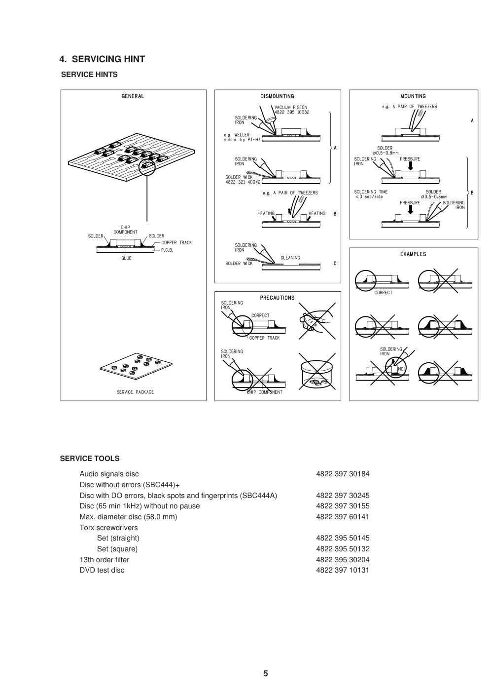
SERVICE TOOLS
Audio signals disc
4822 397 30184
Disc without errors (SBC444)+
Disc with DO errors, black spots and fingerprints (SBC444A)
4822 397 30245
Disc (65 min 1kHz) without no pause
4822 397 30155
Max. diameter disc (58.0 mm)
4822 397 60141
Torx screwdrivers
Set (straight)
4822 395 50145
Set (square)
4822 395 50132
13th order filter
4822 395 30204
DVD test disc
4822 397 10131
SERVICE HINTS
4. SERVICING HINT
6
REGIONAL CODES
1
2
2
2
5
5
4
4
3
6
Map of DVD Regions
What are "regional codes"?
Motion picture studios want to control the home release of movies in different countries because theater releases arenít
simultaneous (a movie may come out on DVD in the US when itís just hitting screens in Europe). Therefore they have
required that the DVD standard include codes which can be used to lock out the playback of certain discs in certain geo-
graphical regions. Players sold in each region will have that regionís code built into the player. The player will refuse to play
these "region coded" discs which are not allowed in the region. However, regional codes are entirely optional. Discs without
codes will play on any player in any country. Some studios have already announced that only their new releases will have
regional codes. There are six regions:
1. United States and Canada
2. Europe and Japan
3. Far East (except Japan & China)
4. South America and Oceania
5. Africa and the Middle East
6. China (except Hong Kong)
7
LOCATION OF CUSTOMER CONTROLS
DVD PLAYER DV3100
STANDBY
STANDBY/ON
POWER
OPEN/CLOSE
STOP
PAUSE
PLAY
TITLE
CD
PROG. NKS
RANDOM ALL A
B
CHP/TRK
DVD
MODEL NO.DV3100
COAXIAL
OUT
DIGITAL
OUT
S-VIDEO
OUT
AUDIO
OUT
VIDEO
L
R
PAL
NTSC
AUTO
A/V EUROCONNECTOR
TV
F RO N T PA N E L
DISPLAY WINDOW
R E A R PA N E L
POWER INDICATOR
POWER BUTTON
DISPLAY WINDOW
REMOTE SENSOR
OPEN/CLOSE BUTTON
SKIP/SCAN BUTTONS
DISC TRAY
PLAY BUTTON
PAUSE BUTTON
STOP BUTTON
ANGLE ICON INDICATOR
TITLE NUMBER INDICATOR
S-VIDEO OUT JACK
AV-EURO CONNECTOR
VIDEO OUT JACK
PAL/NTSC
CHAPTER/TRACK NUMBER INDICATOR
TOTAL PLAYING TIME/ELAPSED
TIME INDICATORS
AUDIO OUT1(L/R) JACKS
POWER CORD
Connect to an AC 220~240V, 50Hz
outlet only.
COAXIAL DIGITAL AUDIO OUT JACK
OPERATING STATUS INDICATOR
PROGRAM INDICATOR
DVD INDICATOR
REPEAT PLAYBACK
MODE INDICATORS
CD INDICATOR
RANDOM INDICATOR
8
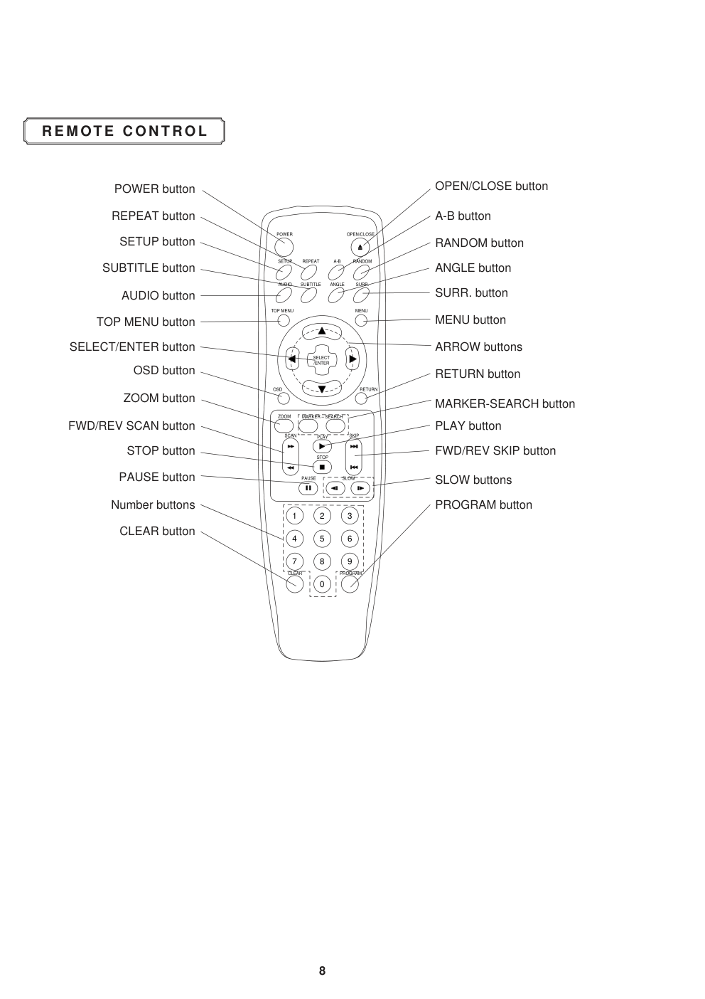
R E M OT E C O N T RO L
POWER button
STOP button
AUDIO button
FWD/REV SCAN button
REPEAT button
TOP MENU button
MENU button
ARROW buttons
RETURN button
PLAY button
FWD/REV SKIP button
SLOW buttons
MARKER-SEARCH button
OPEN/CLOSE button
RANDOM button
A-B button
ANGLE button
SURR. button
OSD button
ZOOM button
SELECT/ENTER button
SUBTITLE button
SETUP button
2
3
1
5
6
4
8
0
9
7
PROGRAM
SKIP
SCAN
PLAY
ZOOM
OSD
TOP MENU
MENU
ANGLE
SELECT
/ENTER
SURR.
SUBTITLE
AUDIO
A-B
RANDOM
REPEAT
POWER
OPEN/CLOSE
SETUP
RETURN
STOP
PAUSE
MARKER – SEARCH
SLOW
CLEAR
PAUSE button
Number buttons
CLEAR button
PROGRAM button
2-1
SECTION 2
CABINET & MAIN CHASSIS
CONTENTS
1. DISASSEMBLY.........................................................................................................................2-2
CABINET DISASSEMBLY ............................................................................................................2-2
CIRCUIT BOARD DISASSEMBLY................................................................................................2-3
2. EXPLODED VIEWS.................................................................................................................2-4
1. Cabinet and Main Frame Section ...........................................................................................2-4
2. Packing Accessory Section ....................................................................................................2-5
2-2
DISASSEMBLY
CAUTION BEFORE STARTING SERVICING
Electronic parts are susceptible to static electricity and may easily damaged, so do not forget to take a
proper grounding treatment as required.
Many screws are used inside the unit. To prevent missing, dropping, etc. of the screws, always use a
magnetized screw driver in servicing. Several kinds of screws are used and some of them need special
cautions. That is, take care of the tapping screws securing molded patrs and fine pitch screws used to secure
metal parts. If they are used improperly, the screw holes will be easily damaged and the parts can not be fixed.
Top Case
(A)
(A)
(A)
(A)
(A)
(A)
(A)
Tray Door
Disc Tray
Front Panel
Stopper
Stopper
(B)
(B)
CABINET DISASSEMBLY
1. Top Case
1. Release 7 screws (A). (See Fig. 2-1)
2. Lift the top case with holding the back of it,
and remove it in the direction of the arrow
Fig. 2-1
Fig. 2-2
Fig. 2-3
3. Front Panel
1. Eject the disc tray. (See Fig. 2-2)
2. Remove the tray door. (See Fig. 2-2)
3. Release 2 screws (B).
4. Pull the front panel toward you while pressing
7 stoppers to disengage, and remove the front
panel. (See Fig. 2-3)
(A)
Press open/close button to open the tray. If the
tray doesn't work, insert and push a small screw-
driver in the emergency eject hole (A) at the right
side. Then the tray comes out. After the first
centimeter it is possible to pull the tray out by
hand. Release the door cover of the tray.
REMARK: Before disassemble the front panel.
2.Tray Door
1.Eject the disc tray.
2.Lift up the tray door in the direction of the
arrow.
2-3
Main Circuit Board
(C)
(C)
(C)
(C)
(C)
(C)
(C)
(C)
(C)
(C)
(C)
(C)
Power Code
Interface
Circuit
Board
(D)
(D)
Key
Circuit Board
(E)
(E)
(E)(E)
Fig. 2-4
Fig. 2-5
1. Disassembling of Main Circuit Board
and Interface Board
1. Remove the top case.(See Fig. 2-1)
2. Remove 12 screw (C).
3. Remove the deck from Main Circuit Board.
4. Remove Main Circuit Board from Interface
Board.
5. Remove 2 screw (D).
6. Remove Interface Board from the chassis.
CIRCUIT BOARD DISASSEMBLY
Note: Before removing the main circuit board, be sure to shortcircuit the laserdiode output land.
After replacing the main circuit board, open the land after inserting the flexible connector.
(Refer to Mechanism Disassembly)
2. Digitron and Key Circuit Board
1. Remove the front panel.(See Fig. 2-3)
2. Release 4 screws (E), and remove the digitron
circuit board.
2-4
EXPLODED VIEWS
1. Cabinet and Main Frame Section
280
465
467
465
465
463
A46
463
463
279
275
332
PBP00
PBT00
283
260
467
300
467
A48
A43
250
462
462
463
463
452
452
285
Jack
Scart
A
5
4
3
2
1
B
C
D
2-5
2.Packing Accessory Section
BATTERY
808
PACKING SHEET
804
PACKING
803
811
812
OWNER'S MANUAL
VIDEO
AUDIO
801
REMOTE CONTROLLER
900
BOX CARTON
802
PACKING
803
POS.
VERS.
PART NO.
DESCRIPTON
PART NO.
NO.
COLOR
(ANAM)
(MJI)
250
nsp
TOP COVER (BLACK)
nsp
260
/N1B
nsp
CHASSIS ASSY MAIN (/N1B)
nsp
275
nsp
HOLDER MAIN PCB
nsp
279
nsp
HOLDER CONNECTOR
nsp
280
/N1B
9965 000 06951 PANEL ASSY FRONT (/N1B)
304W248510
283
/N1B
9965 000 06952 DOOR ASSY (BLACK)
304W063500
300
/N1B
9965 000 06953 MAINS CORD (/N1B)
*YC000510R
332
nsp
PLATE MAIN GND
nsp
429
nsp
SCREW B-TITE
nsp
430
nsp
SCREW +D2.0 6MM
nsp
SWRCH16A/NIY 4.5MM
430
nsp
SCREW +D2.0 6MM
nsp
SWRCH16A/NIY 4.5MM
431
nsp
SCREW +D2.0 6MM
SWRCH16A/ZNBK 4MM 1
nsp
432
nsp
SCREW MACHINE
nsp
432
nsp
SCREW MACHINE
nsp
452
nsp
SCREW SPECIAL
nsp
462
nsp
SCREW DECORATION
nsp
463
nsp
SCREW SPECIAL
nsp
465
nsp
SCREW SPECIAL (3X10 BK)
nsp
467
nsp
SCREW SPECIAL (3X8 BK)
nsp
POS.
VERS.
PART NO.
DESCRIPTON
PART NO.
NO.
COLOR
(ANAM)
(MJI)
801
/N1B
9965 000 06954 USER GUIDE (/N1B)
304W851310
802
nsp
BOX
nsp
803
nsp
PACKING
nsp
804
nsp
SHEE
nsp
808
nsp
BATTERY AAA(R03)
nsp
811
nsp
PHONO CORD (YL)
nsp
812
nsp
PHONO CORD (RD/WH)
nsp
900
9965 000 06955 REMOTE CONTROLLER
ZK304W0010
3-1
SECTION 3
ELECTRICAL
CONTENTS
ELECTRICAL TROUBLESHOOTING GUIDE......................................................................3-2
1. Power(SMPS) Circuit...............................................................................................................3-2
2. µ-com Circuit...........................................................................................................................3-3
3. MPEG Circuit ...........................................................................................................................3-6
4. Front Circuit(Digitron & Key) .................................................................................................3-7
5. RF/Servo Circuit ......................................................................................................................3-8
BLOCK DIAGRAMS ..................................................................................................................3-12
1. Overall Block Diagram..........................................................................................................3-12
2. Power (SMPS) Block Diagram..............................................................................................3-13
3. RF/CD DSP/DVD DSP/DVD servo Block Diagram..............................................................3-14
4. Audio Block Diagram ............................................................................................................3-15
5. MPEG Block Diagram ..........................................................................................................3-16
6. µ-COM Block Diagram..........................................................................................................3-17
CIRCUIT DIAGRAMS ...............................................................................................................3-18
1. Power (SMPS) Circuit Diagram ............................................................................................3-18
2. DVD DSP Circuit Diagram.....................................................................................................3-20
3. Drive & RF Circuit Diagram...................................................................................................3-22
4. MPEG Circuit Diagram ..........................................................................................................3-24
• WAVEFORMS...........................................................................................................................3-26
5. Audio DM & 5.1CH Circuit Diagram .....................................................................................3-28
6. µ-COM/Expander...................................................................................................................3-30
7. DIGITRON & Key Circuit Diagram ........................................................................................3-32
8. Jack Circuit Diagram.............................................................................................................3-34
PRINTED CIRCUIT DIAGRAMS ...........................................................................................3-36
1. MAIN P.C.BOARD...................................................................................................................3-36
2. POWER,A/V,FRONT P.C.BOARD...........................................................................................3-38
3. KEY P.C.BOARD ....................................................................................................................3-40
4. POWER LED P.C.BOARD ......................................................................................................3-41
3-2
ELECTRICAL TROUBLESHOOTING GUIDE
No 5V_D
or 5V_A .
No 5.2VA.
Is 5.2VA section working?
Is oscillation present at the
Base of Q108?
Replace Q108.
Check L103, C116, 117.
Replace R111.
Replace BD101.
(Bridge rectifier)
Check Fuse(F101).
Is R111 1Ω?
Check D105.
Replace Q101, 102.
Is 5.2V applied to IC102
Pin 1?
Is there a DC voltage at the
(+) terminal of BD101?
Check R127, 128.
(SHUTDOWN CKT)
1. Power(SMPS) Circuit
No VF+
Is 5.2VA section working?
Replace D109.
Is oscillation present at the
anode of D109?
NO
NO
NO
NO
YES
YES
YES
YES
YES
YES
YES
YES
A.
B.
NO
NO
NO
3-3
Replace IC506.
Refer to Front Part
Check short
Reconnect it.
2. µ-COM Circuit
A. No Power
Does Logo appear
on the screen?
Is oscillation of
X501 normal?
Are IC503 Pins 14, 288
and 29 normal?
Do all five Bars appear?
Does Bar appear at FLD?
Is P5901
connected normally?
Is P5901 Pin 24 normal?
The
waveform on A[00:21]
and D[00:15] of IC501
normal?
Are IC506 Pins 7, 8 normal?
Replace Main B/D.
Check the oscillation
Check short.
OK
Replace IC501
or IC503.
Check power.
(Refer to power)
If power is
normal
OK
POWER ON
1
1
YES
YES
YES
YES
YES
YES
YES
YES
A
NO
NO
NO
NO
NO
NO
NO
NO
NO
NO
A
3-4
B. Audio abnormal
D. Open/Close abnormal
Check the
connection of P5901.
Check IC501 Pins 13, 14.
Check Audio jack.
YES (If OK)
YES
NO
NO
YES
YES (If OK)
YES
YES (If OK)
YES (If OK)
YES (If OK)
Check PLL FC of MPEG part.
Refer to Audio part.
Refer to MPEG part.
Replace B/D.
Check Front.
Reconnect it.
Refer to SERVO part.
Check the connection of MD.
AUDIO ABNORMAL
OPEN/CLOSE ABNORMAL
C. Video abnormal
Check Video jack.
YES (If OK)
YES (If OK)
YES (If OK)
YES (If OK)
Refer to Video part.
Refer to Encoder part.
Refer to MPEG part.
Replace B/D.
VIDEO ABNORMAL
3-5
E. Picture abnormal
Check the disc.
If OK
YES (If OK)
YES (If OK)
Refer to Servo part
Check PLL IC of MPEG part
Check DSP
Check MPEG
YES (If OK)
Replace B/D
PICTURE ABNORMAL
F. Disc Error
Check Disc
YES (If OK)
YES (If OK)
Refer to Servo part
Replace B/D
DISC ERROR
3-6
Power is on
Does LG Logo appear
on the screen?
Does the
moving picture of the DVD Disc
play on the screen
normally?
Is MPEG data signal normal?
Is error signal normal?
Is MPEG data signal normal?
Is Clock normal?
Does the audio
sound output from MPEG
decoder?
Does the
moving picture of the video
CD play on the screen
normally?
Does the audio sound
output normally?
END
Check power & clock.
Check CD/DVD DSP output
signal.
Check MPEG Decoder input
signal.
Check CD/DVD DSP output
signal.
Check MPEG Decoder input
signal.
Check CD/DVD DSP output
signal.
Check MPEG Decoder input
signal.
Check clock signal
Check clock signal
YES
YES
YES
YES
YES
YES
YES
YES
YES
YES
NO
NO
NO
OK
OK
OK
OK
NO
NO
NO
NO
NO
3. MPEG Circuit
_ OPTION
_ If included VCD function.
3-7
NO
NO
NO
START
Does remote control
work normally?
Do all the
buttons work
normally?
Check waveform of
IC901 Pin 13.
Check waveform
of IC901 Pin 2.
Is Digitron on normally?
LED ON?
Check waveform
of IC901 Pin 6.
Is oscillation of
X901 normal?
Is waveform of IC901
Pin 76 normal?
Check waveform
of IC901 Pin 13.
Does pulse
waveform of RC901 Pin 1
appear?
Is IC901
Pin 24 connected to
RC901 Pin 1 ?
Is RC901 Pin 2 5V?
Power on.
Check and replace
R903,R912, R904, R905,
R941, R906, R907.
Solder defective parts again.
Solder defective parts
Replace Q901.
Solder Key part.
Check Power.
Replace IC902.
Replace IC901.
Replace LED901.
Replace RC901.
Re-solder.
Recheck
Replace IC901.
Complete repairing Front B/D.
NO
NO
NO
NO
NO
NO
NO
NO
NO
YES
YES
YES
YES
YES
YES
YES
YES
YES
YES
YES
YES
YES
YES
YES
YES
CD
4. Front Circuit (Digitron & key)
3-8
Does signal pulse
input to IC201 Pins 58, 59 when
the power is on?
Does signal goes
"High" to IC201 Pin194 when the
power is on?
Does
TTL pulse output to
IC201 Pins 140, 142?
Does
33.8688MHz clock input
to IC201 Pin 63?
Is IC201
Pins 83, 84, 88, 89 voltage
about 2.2V?
Replace IC201
(IC206 soldering or IC defect).
Check power circuit.
Check "2.µ-COM Part".
Replace X301 or IC304
(30MHz clock defect)
CHECK POINT(General)
5. RF/Servo Circuit
A.
END
NO
NO
NO
NO
NO
YES
YES
YES
YES
YES
3-9
Does tray open or close?
Does the pick-up
slide inner or outer
track?
Fig.1. SLED Driver waveform
Fig.2. Focus Driver waveform
Does
the voltage change
at PMD04 Pins 1, 2 more than
2V on the basis of
3.8V?
Pressing
the open/close key
repeatedly, check the voltage of IC2M1
Pins 13, 14 change
0V to 5V
Does
PMD03 Pin 7 change
high to low?
Does
the pick-up lens move up
and down?
Check Focus Driver output.
(IC201 Pin 83, IC2M1 Pins 37, 38)
Check SLED Driver output.
IC201 Pin 88 IC2M1 Pins 28, 29.
IC201 Pin 88 no output : IC201 is defective
IC2M1 Pin 18 no output : IC2M1 is defective
IC201 Pin 83 no output : IC201 is defective
IC2M1 Pins 1, 2 no output : IC2M1 is defective
DECK assembly is defective.
Slide the pick-up to
inner track.
.Power on
Check loading Part.
Push Pick-up to inner track to
the end by hand.
DECK assembly is defective.
(Limit sw)
check µ-COM Part.
Replace IC2M1.
No disc
B.
END
NO
NO
NO
NO
NO
NO
YES
YES
YES
YES
YES
YES
3-10
FOCUS ON?
Check
the focus error moving the
lens up and down.
(IC2A1 Pin 42)
Does the
TTL level change at IC201
Pin 78 and 132 moving
the lens?
Does the disc turn?
IC201 Pin169 is "High"?
Is OK the track jump.
Does the signal
pulse appear at IC2A1 Pins
39, 29?
Does the screen appear?
OPEN/CLOSE
Replace µ-COM or IC201.
Replace IC201.
Check IC2A1 Pin 11,12,13,14
in DVD Mode
Fig.3. FOCUS ERROR waveform
IC201 no output : Pick-up is defective.
Check IC201 and IC2M1 when PMD03 Pin 6 is abnormal
Check IC2M1 Pin 21, PMD03
Pin 6 turn when the IC2M1
Pin 21 is less than 2.2V.
Check A
Video Part is defective.
Check "5.MPEG Circuit."
Check "7.OSD/Video Circuit."
Replace µ-COM part.
IC2A1 is defective.
DISC IN
C.
END
NO
NO
NO
NO
NO
NO
NO
NO
YES
YES
YES
YES
YES
YES
YES
YES
3-11
Is the eye-pattern vivid?
Does the
sawtooth waveform emit
at IC2A1 Pin 41?
Does the 1.6V emit?
Check RF Eye-Pattern.
RF : 1.5-1.6V(IC2A1 Pin 57)
Fig.5. RF
waveform
Check IC2A1 Pins 5, 6, 7, 8.
No signal: Pick-up is defective
Replace IC201.
Check IC201 Pin84.
No signal at IC201 : IC201 is defective
• Check IC201 Pin 162.
• Check the clock at the IC201 Pins 28, 30.
• Both are normal : IC201 is defective
Replace IC2A1.
CHECK A
D.
END
NO
NO
NO
NO
YES
YES
YES
YES
3-12
BLOCK DIAGRAMS
1. Overall Block Diagram
DISC
SPINDLE
MOTOR
LOADING
MOTOR
Focus, tracking sled
VF+
VF-
-24V
8V
5.2VA
5V_A
5V_D
3.3V_M
3.3V
2.5V
8V
A.GND,D.NGD,M.GND
loading drive
spindle
loading
CD,DVD:A,B,C,D,E,F
MIRR,TZC
DVD_LDQM,DVD_SD,CSI
DVD_MA[0:11]
DVD_MD[0:15]
DVD_SD_CAS,
DVD_SD_RAS
DVD_SD_CLK
DVD_MWE
DVD_DATA[0:7]
DVD_SD_CSO,
DVD_UDQM
ICADDR[0:8]
ICDATA[00:15]
SDCLKI, ZISENB
REQZI
3.38688MHz
DA_DATA,
DA_LRCK,
DA_BCK
D[00:07]
S_CLK,S_DATA,
DPLL_L
IIC_DATA,
IIC_CLK
A[00:02]
DA_XCK
CVBS,
Y,C
Y(G),
PB(B)
PR(R)
CVBS,Y,C
Y(G)PB(B),PR(R)
27MHz
FE,TE,RFRP,SBADD,DVD/CD RF
TEBAL,FEBAL,
DPOCTL,EQF,EQB
MON,SPINDLE_DRV
FDO,TDO,
FMO
AC100-
240V,
50~
60Hz
FL DISPLAY
REMOCON
RECEIVER
KEY Input
SPINDLE_FG
POWER CONTROL
SENS,FOK,MIRR
MSDATO,DEFECT,DSP_SENSE,
SQSO,SQCK,SCOR,AO[0:5]
XLAT,S_CLK,S_DATA,DO[0:7]
PICK
UP
IC2A1
33P3721
RF Signal
Processor
IC205
DRAM
256K x 16bit
IC201
DVDSP-3301
CD/DVD DSP
DVD SERVO
IC501
SH7034
MAIN
u-COM
IC301
ZiVA-3
MPEG A/V
Decoder
IC305
SAA7126/8
VIDEO
Encoder
IC302
GM72V1621
1M x 16bit
SDRAM
IC303
GM72V1621
1M x 16bit
SDRAM
IC304
PLL1700
CLOCK
GENERATROR
IC2M1
KA3032
Motor Driver
POWER
BOARD
IC901
LC866112
OPEN S/W
CD DECK MECHANISM
CLOSE S/W
LIMIT S/W
M
M
DAC_LO,
S_CLK,
S_DATA
DA_DATA,
DA_LRCK,
DA_BCK
27MHz
X-TAL
L/R
VDATA[0:7]
Hsync
Vsync
IC306/307
BA7660
6dB AMP
AMP
VIDEO
'OUT
L/R
CVBS
Y
C
Y(G) PB(B) PR(R)
IC401/451
PCM1723E
AUDIO
DAC
3-13
2. Power(SMPS) Block Diagram
RECTIFIER(FLD)
RECTIFIER
LINE FILTER
SWITCHING TR
RECTIFIER(14V)
LPF
REG(8V)
REG(3.3V)
REG(3.3V)
PWR ON/OFF
F+
F-
-24VA
12VA
8V
5.2VA
5V_D
5V_A
3.3V
3.3V_M
2.5V
LPF
RECTIFIER(9V)
RECTIFIER(5.2V)
TRANS
LPF
FEED B.
3-14
IC2A1
33P3721
RF Signal
Processdr
IC206
DVDSP-3301
CD/DVD DSP
DVD SERVO
DRAM
256K x 16bit
IC2M1
KA3032
SpindleMotor,LoadingMotor,
Actuator Driver
PICK
UP
DVD:A,B,C,D,
FE,TE,PI,SBADD
SENS,FOK,SLD_FG,
MSDATO,DEFECT,DSP_SENSE
SQSO,SQCK,SCOR
XLAT,S_CLK,S_DATA
DSP_CS,/WR,/RD
DO[0:7]
AO[0:5]
DVD_DATA[0:7]
MCK
UCOM
I/F
MPEG
I/F
UCOM
I/F
M/D
DVD/CD RF
MIRR,TZC
ICADDR[0:8]
ICDATA[00:15]
MON,MDP
FDO,TDO,FMO
Spindle
focus,tracking,loading,sled
SPINDLE_FG
Load open/close(loading control)
CD:A,B,C,D/E,F
4
4
5
3
3
3
8
6
8
8
2
4
9
16
3. RF/CD DSP/DVD DSP/DVD SERVO Block Diagram
3-15
4. Audio Block Diagram
IC402
LPF &Buffer
NJM4580M
OP AMP
IC401
PCM1716
Audio DAC
U-COM
I/F
DAC_RST
S_DATA
S_CLK
DAC_L0
DA_LRCK
DA_BCK
DA_XCK
DA_DATA0
MPEG
I/F
A/V
JACK
I/F
L
R
L
R
3-16
5. MPEG Block Diagram
DSP
I/F
IC301
ZiVA-3
MPEG A/V
Decoder
IC303
GM72V1621
1M x 16bit
SDRAM
IC302
GM72V1621
1M x 16bit
SDRAM
IC304
PLL1700
CLOCK
GENERATROR
IC305
SAA7126/8
NTSC/PAL
Encoder
IC306
BA7660FS
6dB AMP
IC307
BA7660FS
6dB AMP
27MHz
X-TAL
U-COM
I/F
DVD_DATA[0:7]
DAI_DATA
DA_DATA[0:3]
DA_BCK,DA_XCK,DA_LRCK
SPDIF
HSYNC,VSYNC
CVBS
Y
C
Y
PB
PR
CVBS
AUDIO
I/F
A/V
JACK
I/F
U-COM
I/F
U-COM
I/F
SERVO
I/F
Y
C
Y
PB
PR
VDATA[0:7]
DA_XCK
MPEG_CLK
IIC_DATA,IIC_CLK
IIC_DATA,IIC_CLK
DAC_RST
8
SDCLK1,ZISENB
REQZ1
2
2
A[00:02]
D[00:07]
MPEG_ERROR
MPEG_RST
DVD_SD_CS0,DVD_UDQM
DVD_MD[0:15]
DVD_MA[0:11]
DVD_SD_CAS
DVD_SD_RAS
DVD_SD_CLK
DVD_MWE
DVD_LDQM
DVD_SD_CS1
S_CLK,S_DATA
版权声明
1. 本站所有素材,仅限学习交流,仅展示部分内容,如需查看完整内容,请下载原文件。
2. 会员在本站下载的所有素材,只拥有使用权,著作权归原作者所有。
3. 所有素材,未经合法授权,请勿用于商业用途,会员不得以任何形式发布、传播、复制、转售该素材,否则一律封号处理。
4. 如果素材损害你的权益请联系客服QQ:77594475 处理。