现代H-LCD1702液晶显示器维修手册
 "现代H-LCD1702液晶显示器维修手册-0")
 "现代H-LCD1702液晶显示器维修手册-1")
 "现代H-LCD1702液晶显示器维修手册-2")
 "现代H-LCD1702液晶显示器维修手册-3")
 "现代H-LCD1702液晶显示器维修手册-4")
 "现代H-LCD1702液晶显示器维修手册-5")
 "现代H-LCD1702液晶显示器维修手册-6")
 "现代H-LCD1702液晶显示器维修手册-7")
 "现代H-LCD1702液晶显示器维修手册-8")
 "现代H-LCD1702液晶显示器维修手册-9")
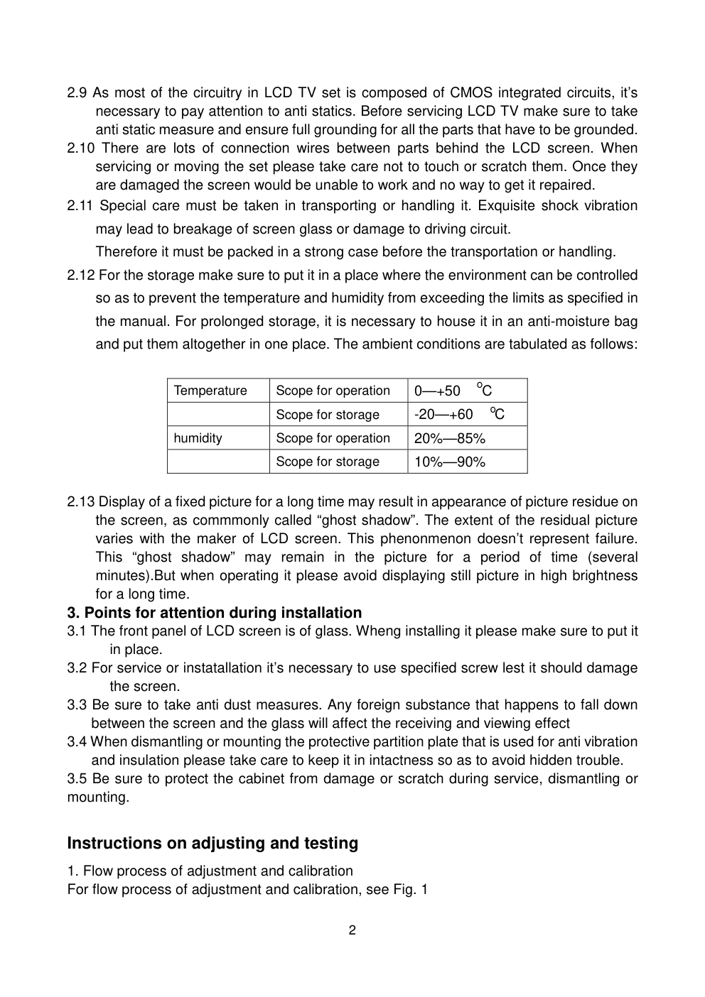
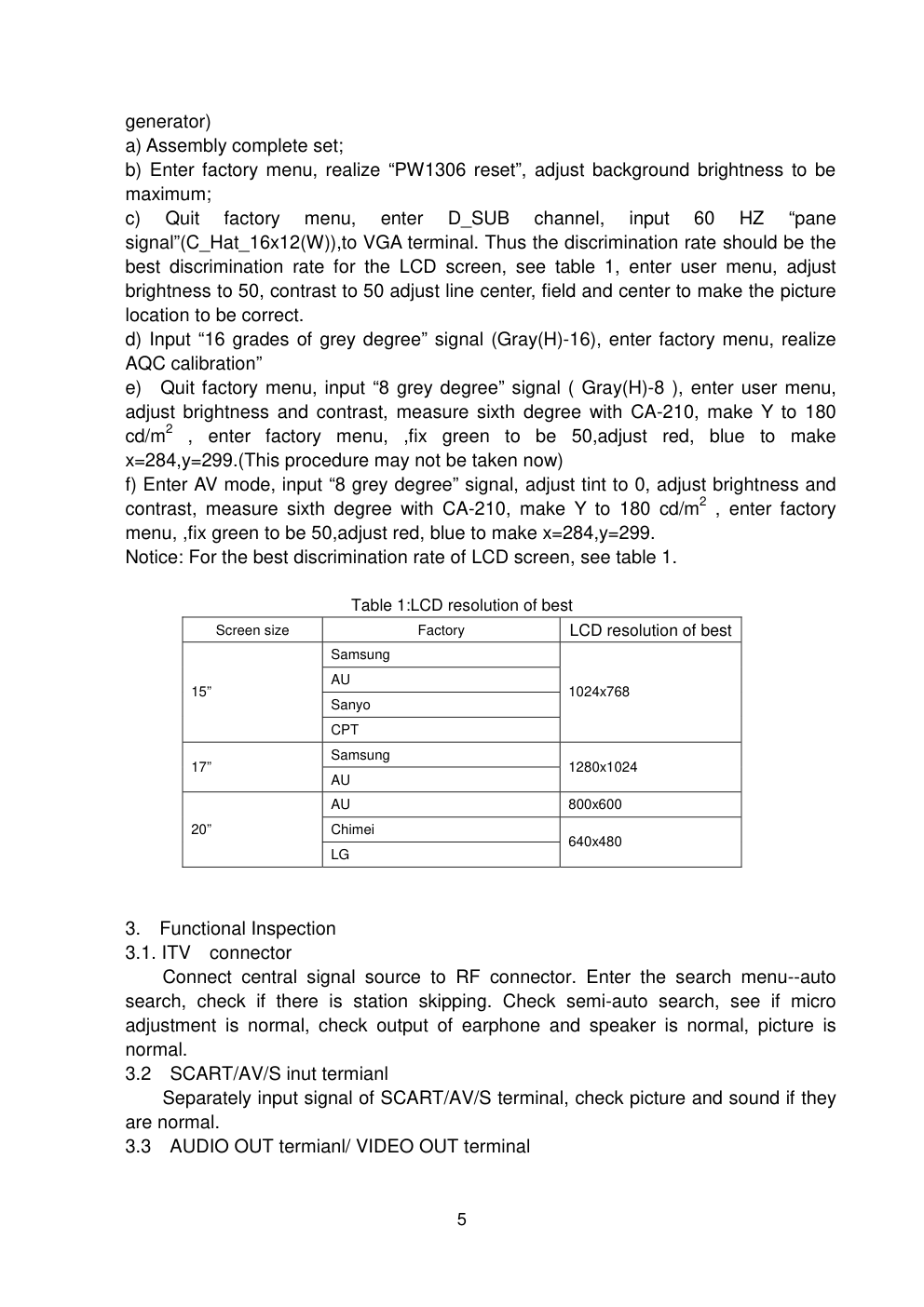
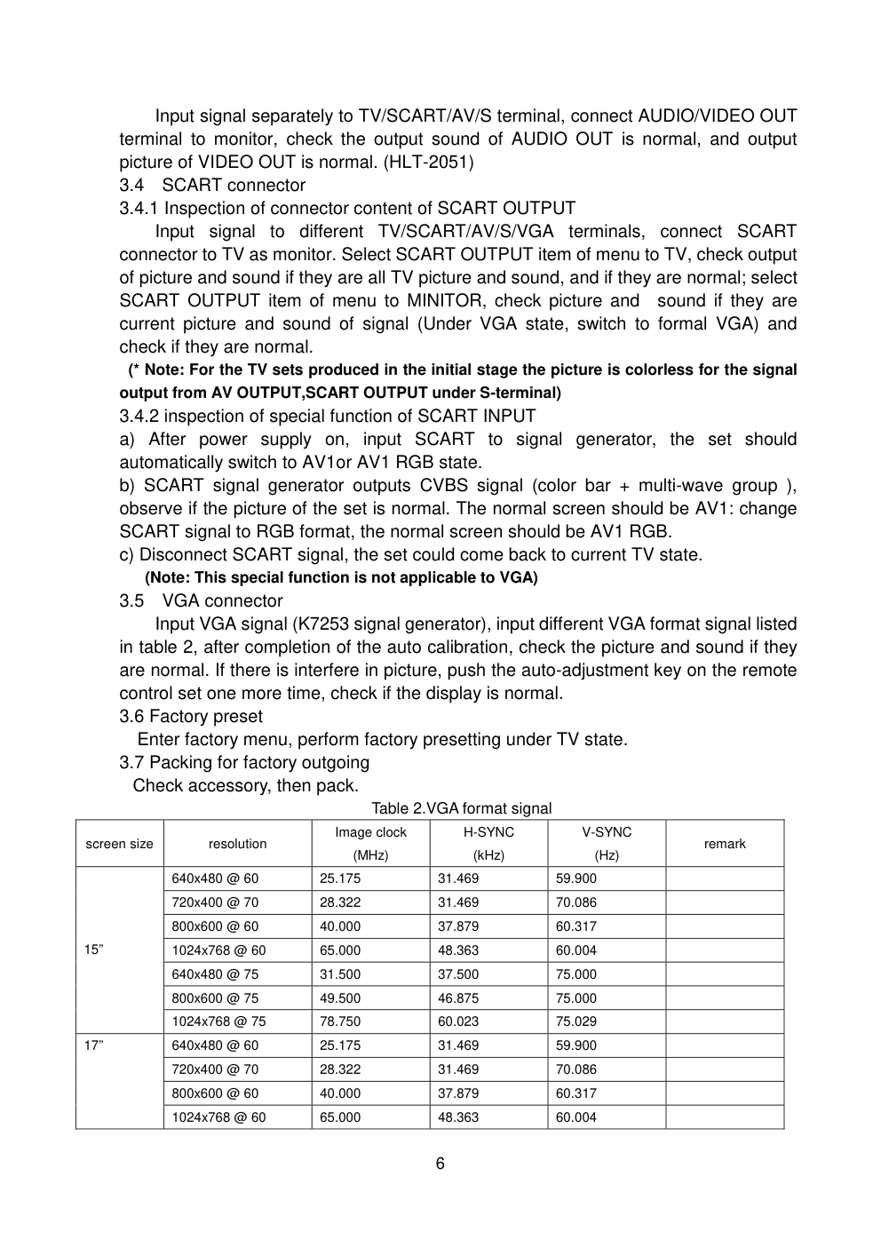
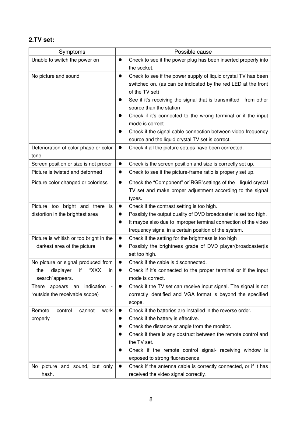
Service manual LCD Model: H-LCD1702 VER 1.1 Prepared Frolov V. 14022005 1 Safety instructions 1 Instructions 1.1 Be sure to switch off the power supply before replacing or welding any components or inserting/plugging in connection wire 1.2 Anti static measures to be taken (throughout the entire production process!): 1.2.1 Do not touch here and there by hand at will; 1.2.2 Be sure to use anti static electric iron; 1.2.3 It’s a must for the welder to wear anti static gloves. 1.3 Please refer to the detailed list before replacing components that have special safety requirements. Do not change the specs and type at will. 2 Points for attention in servicing of LCD 2.1 Screens are different from one model to another and therefore not interchangeable. Be sure to use the screen of the original model for replacement. 2.2 The operation voltage of LCD screen is 700-825V. Be sure to take proper measures in protecting yourself and the machine when testing the system in the course of normal operation or right after the power is switched off. Please do not touch the circuit or the metal part of the module that is in operation mode. Relevant operation is possible only one minute after the power is switched off. 2.3 Do not use any adapter that is not identical with the TV set. Otherwise it will cause fire or damage to the set. 2.4 Never operate the set or do any installation work in bad environment such as wet bathroom, laundry, kitchen,or nearby fire source, heating equipment and devices or exposure to sunlight etc. Otherwise bad effect will result. 2.5 If any foreign substance such as water, liquid, metal slices or other matters happens to fall into the module, be sure to cut the power off immediately and do not move anything on the module lest it should cause fire or electric shock due to contact with the high voltage or short circuit. 2.6 Should there be smoke, abnormal smell or sound from the module, please shut the power off at once. Likewise, if the screen is not working after the power is on or in the course of operation, the power must be cut off immediately and no more operation is allowed under the same condition. 2.7 Do not pull out or plug in the connection wire when the module is in operation or just after the power is off because in this case relatively high voltage still remains in the capacitor of the driving circuit.Please wait at least one minute before the pulling out or plugging in the connection wire. 2.8 When operating or installing LCD please don’t subject the LCD components to bending, twisting or extrusion, collision lest mishap should result. Attention: This service manual is only for service personnel to take reference with. Before servicing please read the following points carefully. 2 2.9 As most of the circuitry in LCD TV set is composed of CMOS integrated circuits, it’s necessary to pay attention to anti statics. Before servicing LCD TV make sure to take anti static measure and ensure full grounding for all the parts that have to be grounded. 2.10 There are lots of connection wires between parts behind the LCD screen. When servicing or moving the set please take care not to touch or scratch them. Once they are damaged the screen would be unable to work and no way to get it repaired. 2.11 Special care must be taken in transporting or handling it. Exquisite shock vibration may lead to breakage of screen glass or damage to driving circuit. Therefore it must be packed in a strong case before the transportation or handling. 2.12 For the storage make sure to put it in a place where the environment can be controlled so as to prevent the temperature and humidity from exceeding the limits as specified in the manual. For prolonged storage, it is necessary to house it in an anti-moisture bag and put them altogether in one place. The ambient conditions are tabulated as follows: Temperature Scope for operation 0—+50 C Scope for storage -20—+60 C humidity Scope for operation 20%—85% Scope for storage 10%—90% 2.13 Display of a fixed picture for a long time may result in appearance of picture residue on the screen, as commmonly called “ghost shadow”. The extent of the residual picture varies with the maker of LCD screen. This phenonmenon doesn’t represent failure. This “ghost shadow” may remain in the picture for a period of time (several minutes).But when operating it please avoid displaying still picture in high brightness for a long time. 3. Points for attention during installation 3.1 The front panel of LCD screen is of glass. Wheng installing it please make sure to put it in place. 3.2 For service or instatallation it’s necessary to use specified screw lest it should damage the screen. 3.3 Be sure to take anti dust measures. Any foreign substance that happens to fall down between the screen and the glass will affect the receiving and viewing effect 3.4 When dismantling or mounting the protective partition plate that is used for anti vibration and insulation please take care to keep it in intactness so as to avoid hidden trouble. 3.5 Be sure to protect the cabinet from damage or scratch during service, dismantling or mounting. Instructions on adjusting and testing 1. Flow process of adjustment and calibration For flow process of adjustment and calibration, see Fig. 1 3 Fig. 1 Figure 1. Flow process of adjustment and calibration Input VGA signal and check if display is normal in the state of PC and various functions (analog quantity control, line/field center etc.) Check accessories and then packing Check if N4, N20, N303, N302 has been FLASH written. Produce main board, TV board on line Check main board Check TV board Combined test for general assembly Connect to central signal source, check if various TV functions (station skipping, modulate quantity control etc), check if the output of earphone and speaker are normal Input SCART/AV/S signal, check different functions of SCART/AV/S terminals Adjust TV board Input TV/AV/ S terminal/SCART/VGA signals, select separately SCART OUTPUT state to be TV or MONITOR, check if the function of SCART OUTPUT is normal 4 2.Adjustment and calibration deacription 2.1 Method to enter factory menu Push MUTE-MENU-OK-SLEEP key in turn at the interval of 1 second 2.2 Adjustment and calibration equipment Digital multi-meter, signal generator (with SCART/RGB signal output), oscillograph, PC set ( preset the program of flash written), K7253(VGA signal generator), CA210 (LCD white balancer) DVD displayer, TV with SCART connector 1 set, IF signal generator 2.3 Written program Writing the memory unit N4, N20, N303, N302 2.4 Main board adjustment and calibration a) Main board X501 Connect infra-red receiving board (as per connect diagram), insert the output plug of power supply adapter( FSP060-1AD103 for 17,20’) into X1, when the indication lamp of infra-red receiving board should be in red b) Connect PC set. Run FLASH N20 upgrade program, push POWER key on the remote control set, when the indication lamp of infra-red receiving board should be in red c) About 4 minutes later, indication lamp of infra-red receiving board turns to yellow/blue (HLT-1751/HLT-2051), measure L102 PIN2 5.0 V,L107 PIN2 3.3 V, N10 PIN2 1.8 V, and N12 PIN2 1.8 V. d) Write DDC program 2.4 TV board adjustment 2.5.1 IF adjustment a) Input DV 5V into TP2, input 12V to TP6, Input 5V to TP4 and input 0V to TP5, monitor voltage of TP3, input 38.9 MHz signal to TP1, and use a non-inductance screw driver to adjust IFT L207 so that TP3 voltage is 1.65V b) Input DC 5V into TP2, input 12V to TP6, Input 0V to TP4 and input 5V to TP5, monitor voltage of TP3, input 33.9 MHz signal to TP1, adjust potential meter RP202 to set TP3 voltage to 1.65V. c) Connect IF line of tuner, control line L and L’: three disconnected points in total. 2.5.2 Connection of the complete set Connect main board, TV board, infra-red receiving board (as per connect diagram), push POWER key on the remoter control set, when the indication lamp of infra-red receiving board is in yellow/blue (HLT-1751/HLT-2051),measure PIN2 of N301to be 3.3 V on TV board, one end of SMT conductance L632 to be 5V, another end of SMT conductance L632 to be 12V. 2.5.3 AGC Adjustment Receive D-8 signal of 60 db, measure the voltage of positive pole of D201 with DC potential meter. Adjust potential meter RP201 to make reading of potential meter just decrease below 4.0V.Input 100db from antenna, the picture should not appear non-synchronized and distorted, input weak signal of 35 dB--40 dB, color should not disappear, picture synchronizes, normal sound. 2.6 White balance adjustment ( Use LCD special white balancer CA210,K7253 signal 5 generator) a) Assembly complete set; b) Enter factory menu, realize “PW1306 reset”, adjust background brightness to be maximum; c) Quit factory menu, enter D_SUB channel, input 60 HZ “pane signal”(C_Hat_16x12(W)),to VGA terminal. Thus the discrimination rate should be the best discrimination rate for the LCD screen, see table 1, enter user menu, adjust brightness to 50, contrast to 50 adjust line center, field and center to make the picture location to be correct. d) Input “16 grades of grey degree” signal (Gray(H)-16), enter factory menu, realize AQC calibration” e) Quit factory menu, input “8 grey degree” signal ( Gray(H)-8 ), enter user menu, adjust brightness and contrast, measure sixth degree with CA-210, make Y to 180 cd/m2 , enter factory menu, ,fix green to be 50,adjust red, blue to make x=284,y=299.(This procedure may not be taken now) f) Enter AV mode, input “8 grey degree” signal, adjust tint to 0, adjust brightness and contrast, measure sixth degree with CA-210, make Y to 180 cd/m2 , enter factory menu, ,fix green to be 50,adjust red, blue to make x=284,y=299. Notice: For the best discrimination rate of LCD screen, see table 1. Table 1:LCD resolution of best Screen size Factory LCD resolution of best Samsung AU Sanyo 15” CPT 1024x768 Samsung 17” AU 1280x1024 AU 800x600 Chimei 20” LG 640x480 3. Functional Inspection 3.1. ITV connector Connect central signal source to RF connector. Enter the search menu--auto search, check if there is station skipping. Check semi-auto search, see if micro adjustment is normal, check output of earphone and speaker is normal, picture is normal. 3.2 SCART/AV/S inut termianl Separately input signal of SCART/AV/S terminal, check picture and sound if they are normal. 3.3 AUDIO OUT termianl/ VIDEO OUT terminal 6 Input signal separately to TV/SCART/AV/S terminal, connect AUDIO/VIDEO OUT terminal to monitor, check the output sound of AUDIO OUT is normal, and output picture of VIDEO OUT is normal. (HLT-2051) 3.4 SCART connector 3.4.1 Inspection of connector content of SCART OUTPUT Input signal to different TV/SCART/AV/S/VGA terminals, connect SCART connector to TV as monitor. Select SCART OUTPUT item of menu to TV, check output of picture and sound if they are all TV picture and sound, and if they are normal; select SCART OUTPUT item of menu to MINITOR, check picture and sound if they are current picture and sound of signal (Under VGA state, switch to formal VGA) and check if they are normal. (* Note: For the TV sets produced in the initial stage the picture is colorless for the signal output from AV OUTPUT,SCART OUTPUT under S-terminal) 3.4.2 inspection of special function of SCART INPUT a) After power supply on, input SCART to signal generator, the set should automatically switch to AV1or AV1 RGB state. b) SCART signal generator outputs CVBS signal (color bar + multi-wave group ), observe if the picture of the set is normal. The normal screen should be AV1: change SCART signal to RGB format, the normal screen should be AV1 RGB. c) Disconnect SCART signal, the set could come back to current TV state. (Note: This special function is not applicable to VGA) 3.5 VGA connector Input VGA signal (K7253 signal generator), input different VGA format signal listed in table 2, after completion of the auto calibration, check the picture and sound if they are normal. If there is interfere in picture, push the auto-adjustment key on the remote control set one more time, check if the display is normal. 3.6 Factory preset Enter factory menu, perform factory presetting under TV state. 3.7 Packing for factory outgoing Check accessory, then pack. Table 2.VGA format signal screen size resolution Image clock (MHz) H-SYNC (kHz) V-SYNC (Hz) remark 640x480 @ 60 25.175 31.469 59.900 720x400 @ 70 28.322 31.469 70.086 800x600 @ 60 40.000 37.879 60.317 1024x768 @ 60 65.000 48.363 60.004 640x480 @ 75 31.500 37.500 75.000 800x600 @ 75 49.500 46.875 75.000 15” 1024x768 @ 75 78.750 60.023 75.029 640x480 @ 60 25.175 31.469 59.900 720x400 @ 70 28.322 31.469 70.086 800x600 @ 60 40.000 37.879 60.317 17” 1024x768 @ 60 65.000 48.363 60.004 7 640x480 @ 75 31.500 37.500 75.000 800x600 @ 75 49.500 46.875 75.000 1024x768 @ 75 78.750 60.023 75.029 1280x1024@60 108 63.981 60.2 1280x1024@75 135 79.976 75.025 640x480 @ 60 25.175 31.469 59.900 720x400 @ 70 28.322 31.469 70.086 800x600 @ 60 40.000 37.879 60.317 640x480 @ 75 31.500 37.500 75.000 CMOscreen nonsupport 20” 800x600 @ 75 49.500 46.875 75.000 CMOscreen nonsupport Trouble shooting Before servicing please check to find the possible causes of the troubles according to the table below. 1.Antenna: Picture is out of focus or jumping � Bad status in signal receiving � Maybe broadcast signal itself is not good � Check if the outdoor antenna is disconnected. � Check if the antenna is correctly oriented. Fringe in picture � Check if the antenna is correctly oriented. � Maybe there is electric wave reflected from hilltop or building. Picture is interfered by stripe shaped bright spots � Possibly due to interference from automobile, train, high voltage transmission line, neon lamp etc. � Maybe there is interference between antenna and power supply line. Please try to separate them in a longer distance. There appear streaks or light color on the screen � Check if interfered by other equipment and if interfered possibly by the equipment like transmitting antenna, non professional radio station and cellular phone. 8 2.TV set: No picture and sound, but only hash. � Check if the antenna cable is correctly connected, or if it has received the video signal correctly. Symptoms Possible cause Unable to switch the power on � Check to see if the power plug has been inserted properly into the socket. No picture and sound � Check to see if the power supply of liquid crystal TV has been switched on. (as can be indicated by the red LED at the front of the TV set) � See if it’s receiving the signal that is transmitted from other source than the station � Check if it’s connected to the wrong terminal or if the input mode is correct. � Check if the signal cable connection between video frequency source and the liquid crystal TV set is correct. Deterioration of color phase or color tone � Check if all the picture setups have been corrected. Screen position or size is not proper � Check is the screen position and size is correctly set up. Picture is twisted and deformed � Check to see if the picture-frame ratio is properly set up. Picture color changed or colorless � Check the “Component” or”RGB”settings of the liquid crystal TV set and make proper adjustment according to the signal types. Picture too bright and there is distortion in the brightest area � Check if the contrast setting is too high. � Possibly the output quality of DVD broadcaster is set too high. � It maybe also due to improper terminal connection of the video frequency signal in a certain position of the system. Picture is whitish or too bright in the darkest area of the picture � Check if the setting for the brightness is too high � Possibly the brightness grade of DVD player(broadcaster)is set too high. No picture or signal produced from the displayer if “XXX in search”appears. � Check if the cable is disconnected. � Check if it’s connected to the proper terminal or if the input mode is correct. There appears an indication - “outside the receivable scope) � Check if the TV set can receive input signal. The signal is not correctly identified and VGA format is beyond the specified scope. Remote control cannot work properly � Check if the batteries are installed in the reverse order. � Check if the battery is effective. � Check the distance or angle from the monitor. � Check if there is any obstruct between the remote control and the TV set. � Check if the remote control signal- receiving window is exposed to strong fluorescence. 9 Blur picture � Check if the antenna cable is correctly connected. � Of if it has received the right video signal. No sound � Check if the “mute” audio frequency setting is selected. � Check if the sound volume is set to minimum. � Make sure the earphone is not connected. � Check if the cable connection is loose. When playing VHS picture search tape, there are lines at the top or bottom of the picture. � When being played or in pause VHS picture search tape sometimes can’t provide stable picture, which may lead to incorrect display of the liquid crystal TVIn this case please press “auto” key on the remote control so as to enable the liquid crystal TV set to recheck the signal and then to display correct picture signal Method of software upgrading Steps of software upgrading are as follows: 1 Select a serial connection wire and a VGA connection wire and then connect them by means of a patch panel; 2 Use a serial wire to connect the PC to the patch panel and set TV set to off state; 3 Open the software upgrade file holder and double click FlashUpgraderNT(use under window 2000/XP/NT) FlashUpgrader(use under window 98), The following interfaces will show up after running the program: 10 Based on the computer features, set up the serial port(COM Port). Select corresponding serial port (if it’s unable to FLASH WRITE, change to another port). Baud is selected to be 115200. Then select Reset Target After Download. Click FLASH pushbutton, it’s ready to run. For other settings, please refer to the Fig. Above (already defaulted by the system, normally no need to change). 4 Switch on TV set the FLASH write program begins to run; 5 After FLASH write is over, push button “cancel” will become flash. Then shut the main power supply and it’s OK just switch it on again. Note: Do not shut the power off or turn the TV set on during the FLASH write. Otherwise it may lead to no way for flash to rewrite. Simple introduction and work principle of HLT-1751/HLT-2051 HLT-2051 multi-media LCD TV broadcast receiver adopts CMO 20.1 inch LCD display screen as display unit. It has PAL/SECAM B/G,I,D K L L, color system receiving functions and at the same time with AV input, S-VHS input, PC VGA connector and earphone output and other signal connectors. The power supply is outer connection of 12V power supply adaptor HLT-1751/HLT-2051 multi-media LCD TV broadcast receiver consists of RF, video signal board assy”, digit picture processing assy’. RF signal produces picture IF signal and sound IF signal by tuner N201, through Video and Sound saw filter Z201, Z202, and the signals are sent to Video/Sound(VIF/SIF) multi systems signal processor of N202 TDA4470 pin6,pin7,and pin1,pin2, for picture and sound demodulation. The demodulated composite signal, after trapping, is selected by the switch N202, and then output to N303 and ICVCT3833 for decoding. The composite video signal is sent through foot 19 of ICN303VCT3833. After processing there, it is output as analog RGB signal from Pin42, PIN43, PIN44 to digit 11 picture processing assy’. The sound SIF signal is sent to foot 67 of ICN402 MSP3410G for sound processing. The output signal from Pin28,Pin27 of N401MSP3410G is output to sound amplification N404TDA7268(20”TPATP1517). After amplification, it is sent to speaker. Input signals to main board include RGB signals from RF, video signal assy’, VGA signal from personal computer. The 2:1 switches ICN5 BA7657F of five routs select R,G,B signals and then send them to main processor IC PW1306. PW1306 is a main processing IC built-in type X86 CPU, with outer memory 8M Flash(N20)and controls the whole system. The input signal from V-port and G-port is subject to internal arithmetic process and then output in R,G,B of 24 bit TTL to sockets JP3,JP4. Through connection line the signal is sent to CMO LCD screen port for the realization of the picture re-display. Converter DS90C383A/DS90CF383A LVDS converts CMOS/TTL data of 28 digit(DRE<7:0>, DGE<7:0>, DBE<7:0>and LCD timing and control data, FPLINE, FPFEAME, DRDY)to four groups of LVDS INFORMATION FLOW (Low voltage differential signal), then send them to the plane displayer for display. IC BLOCK 1 2 3 4 5 6 7 8 9 10 11 12 24 23 22 21 20 19 18 17 16 15 14 13 1 2 1 2 1 2 1 2 1 2 DET Logic Syncsepa Ground Ground Ground Ground VCC CTL (H: IN1, L: IN2) Red 1 input Green 1 input Blue 1 input Red 2 input Green 2 input Blue 2 input VD 1 input VD 2 input VD output Blue output Composite sync output Composite video input (Sync on Green) Green output Red output HD output HD 2 input HD 1 input HD Sync signal detector BA7657F / BA7657S PW130 Figure 1-1 ImageProcessor Block Diagram A/D R G B Clamp Color Space Converter CLK RGB HS,VS Data MUX Auto Image Optimization DRGB (23:0) DGRGB(23:0) DVS, DHS, DEN, DCLK NMI Interrupt Controller RxD TxD UART Watchdog and Timers Processor ROM/ RAM Interface JTAG Debugger 16-Bit Microprocessor PortA(7:0) GPIO PWM IR Decoder A (19:1) D (15:0) CS (1:0) 2-Wire Serial Microprocessor Bus Memory Out Bus Memory Buffer Processor Memory Interface Memory In Bus OSD VYUV(7:0) VCLK VPEN PW130 ImageProcessor Internal Block Diagram ADC VIDEO PORTD (7:0) Sync Processing HS HSYNC, VSYNC SOG Stripper SOGIN FILT PLL CLK RAIN GAIN BAIN A/D Clamp A/D Clamp VS PowerOn Reset RESET Reset XI XO PLL and Oscillator MCLK DCLK UCLK Scaler Color Matrix OSD and Gain Color Lookup Tables Display Timing Generator Color Space Expander TDA4470 Block Diagram ÏÏ Ï ÏÏ ÏÏ ÏÏ ÏÏ AGC (VIF) Tuner AGC ÏÏ ÏÏ ÏÏ Ï ÏÏ ÏÏ ÏÏ AGC (SIF) Ï Ï Ï Ï Ï Ï Ï 11 10 Tuner Ï Ï Ï Ï Ï Ï Ï Ï 27 28 3 1 2 Ï Ï 5 SIF 2 SIF 1 VCO + phase shift AFC Standard Supply ÏÏ ÏÏ ÏÏ L’ switch VCO 21 20 18 Loop filter 14 Ï Offset comp. (optional) 26 FPLL 0° 90° VIF amp 6 7 8 15 VIF CAGC CBL Take over point SIF input switch CAGC 22 12 4,9,16 13 Standard switch 23 VS Ï Ï 17 CRef Intercarrier (FM / NICAM) 24 FM det. AM det. SIF amp 25 AF (AM) AFC Video 95 10851 Ï Video det. Control ÏÏ ÏÏ 19 AFC switch Ï Ï ÏÏ Figure 1. Block diagram V R L R Audio L S-video HIGH VOLTAGE HIGH VOLTAGE MSP3420G 22 Serial No. of Parts Identification criteria for the bright spot and dark spot of the LCD screen Q’ty allowed Distance between two spots Category criteria 15" 20" 22" 30" 40" 15" 20" 22" 30" 40" One single spot ≤5 ≤2 ≤5 ≤2 ≤3 2 neighboring spots ≤2 ≤1 ≤2 ≤1 ≤1 Bright spot Total No. ≤5 ≤2 ≤5 ≤2 ≤3 ≥15mm One single spot ≤6 ≤7 ≤5 ≤4 ≤10 Two neighboring spots ≤2 ≤2 ≤2 ≤1 ≤5 Dark spots Total No. ≤6 ≤7 ≤5 ≤4 ≤10 ≥15mm ≥10mm ≥5mm Total defected point ≤8 ≤7 ≤5 ≤4 / Notes: 1. Definition of defected point (bright spot, dark spot): It is identified as a defected point if its area exceeds 1/2 of a single picture element (R,G,B). 2. Definition of bright spot: It is identified as a bright spot if it is bright in the state of dark field and its bright size remains unchanged 3. Definition of dark spot: It is identified as a dark spot if it is dark in the state of white field and its dark size remains unchanged 4. Definition of two neighboring points: Defects of a group of picture elements(RB,RG,GB). 15" 17" 20" Sell area Europe Europe Europe America LCD panel Samsung 335-15012-00 AU 335-17050-00 Chimei 335-2000F-00 Back light board 667-L15H3-14 667-L17H3-14 667-L20H3-14A High frequency board 667-L15H3S-55 667-L15H3-55 667-L20H3S-55 Main board 667-L15H3-01S 667-L20H3-01S adapter 302-L1510-02 302-AD16A-02 302-AD16A-02 antetype 203-L15H30-02 Sell area Europe Europe Europe America LCD panel AU335-15112-00 AU335-2000F-00 Back light board 667-L15H3-14A 667-L20H3-14A High frequency board 667-L15H3S-55 667-L20H3S-55 Main board 667-L15H3-01BS 667-L20H3-01S adapter 302-L1510-02 302-ADA6A-02 antetype 203-L15H30-03 203-L20H30-02 No sound Check N8 pin 14, 15, 22, 23, 38, 39, 46,47 (these pins should have 12V power supply) Check whether N8 pin 4, 27, 28 are normal. Pin 4 should be 2.43V, pin 27 should be 1.46V and pin 28 should be triangle wave. Check L302, X604 pin 5 and pin 6. Check N6 pin 5 and pin 8 signal. Check N8's welding condition. Check N5 pin 27 and pin 28 signal. Check N5 pin 67 signal. Check whether U1 pin 11 have output waveform. Check N8 pin3, pin 5's input signal. Replace N8. Yes No Yes No No No Yes No No 23 Troubleshooting guide No raster Does the logo appear on the screen when turning on the set ? Check whether the adapter supply 12V power to Digital Board. Check whether X101 is properly inserted. Check U125965V. Check whether FUSE is melted. Replace adapter. Check whether U18 pin 63 is high level. Check whether there is R.G.B output at X601 on TV board. Replace TV board. Replace Digital board. Yes Yes Good No Good No No No No TV board troubleshooting No picture but have raster. Measure the waveform of R.G.B Hors, Vers at X7. Check whether N1 has 5V power supply. Check whether X9 pin 1, pin 2 have 5V power input. Replace N2 Replace V105-V17. Replace N1 Measure N1 pin 33, pin 35 waveform. Measure N1 pin 42, pin 44 waveform. Check V105-V107's output waveform. No Yes Yes Yes No No No No No 24 HLT-1751 HLT-2051-01 HLT-2051-02
版权声明
1. 本站所有素材,仅限学习交流,仅展示部分内容,如需查看完整内容,请下载原文件。
2. 会员在本站下载的所有素材,只拥有使用权,著作权归原作者所有。
3. 所有素材,未经合法授权,请勿用于商业用途,会员不得以任何形式发布、传播、复制、转售该素材,否则一律封号处理。
4. 如果素材损害你的权益请联系客服QQ:77594475 处理。