三星LH46DEAPLBCXF液晶显示器维修手册和原理图
 "三星LH46DEAPLBCXF液晶显示器维修手册和原理图-0")
 "三星LH46DEAPLBCXF液晶显示器维修手册和原理图-1")
 "三星LH46DEAPLBCXF液晶显示器维修手册和原理图-2")
 "三星LH46DEAPLBCXF液晶显示器维修手册和原理图-3")
 "三星LH46DEAPLBCXF液晶显示器维修手册和原理图-4")
 "三星LH46DEAPLBCXF液晶显示器维修手册和原理图-5")
 "三星LH46DEAPLBCXF液晶显示器维修手册和原理图-6")
 "三星LH46DEAPLBCXF液晶显示器维修手册和原理图-7")
 "三星LH46DEAPLBCXF液晶显示器维修手册和原理图-8")
 "三星LH46DEAPLBCXF液晶显示器维修手册和原理图-9")
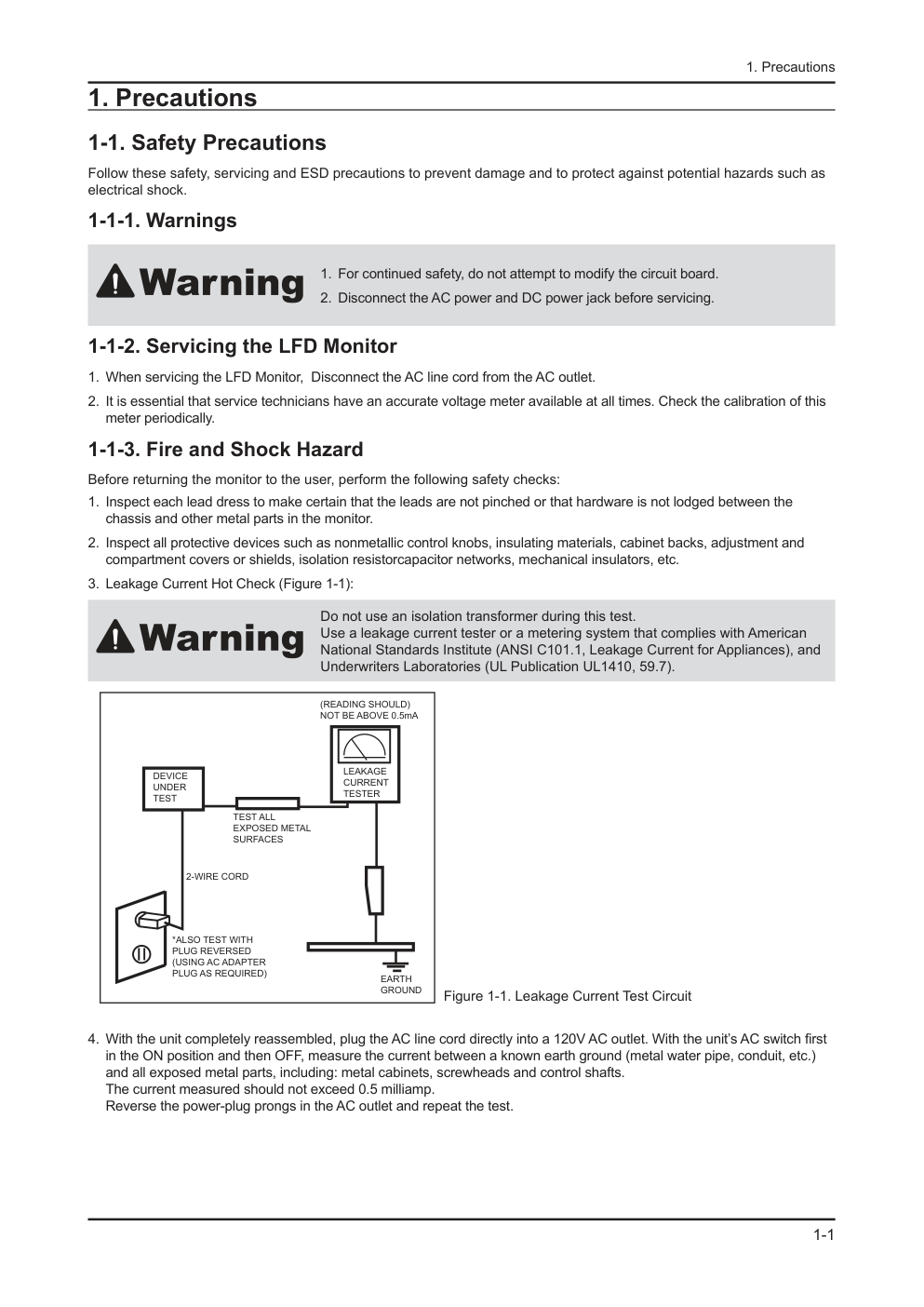
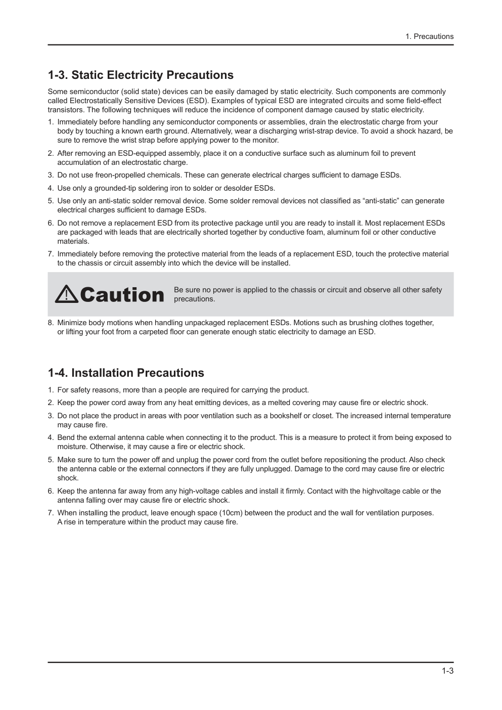
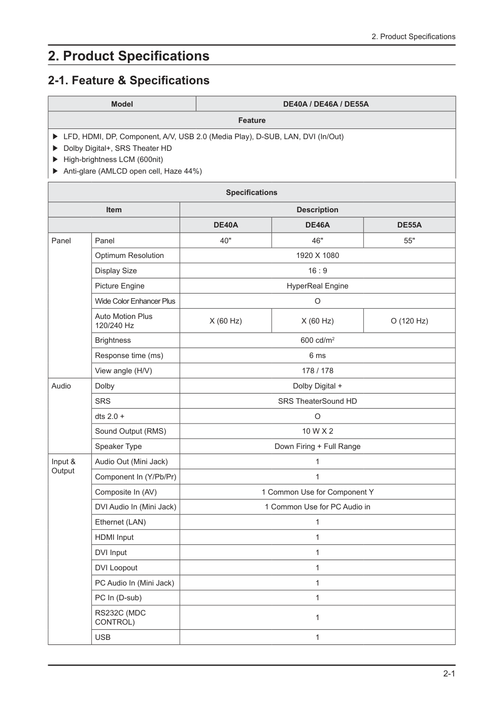
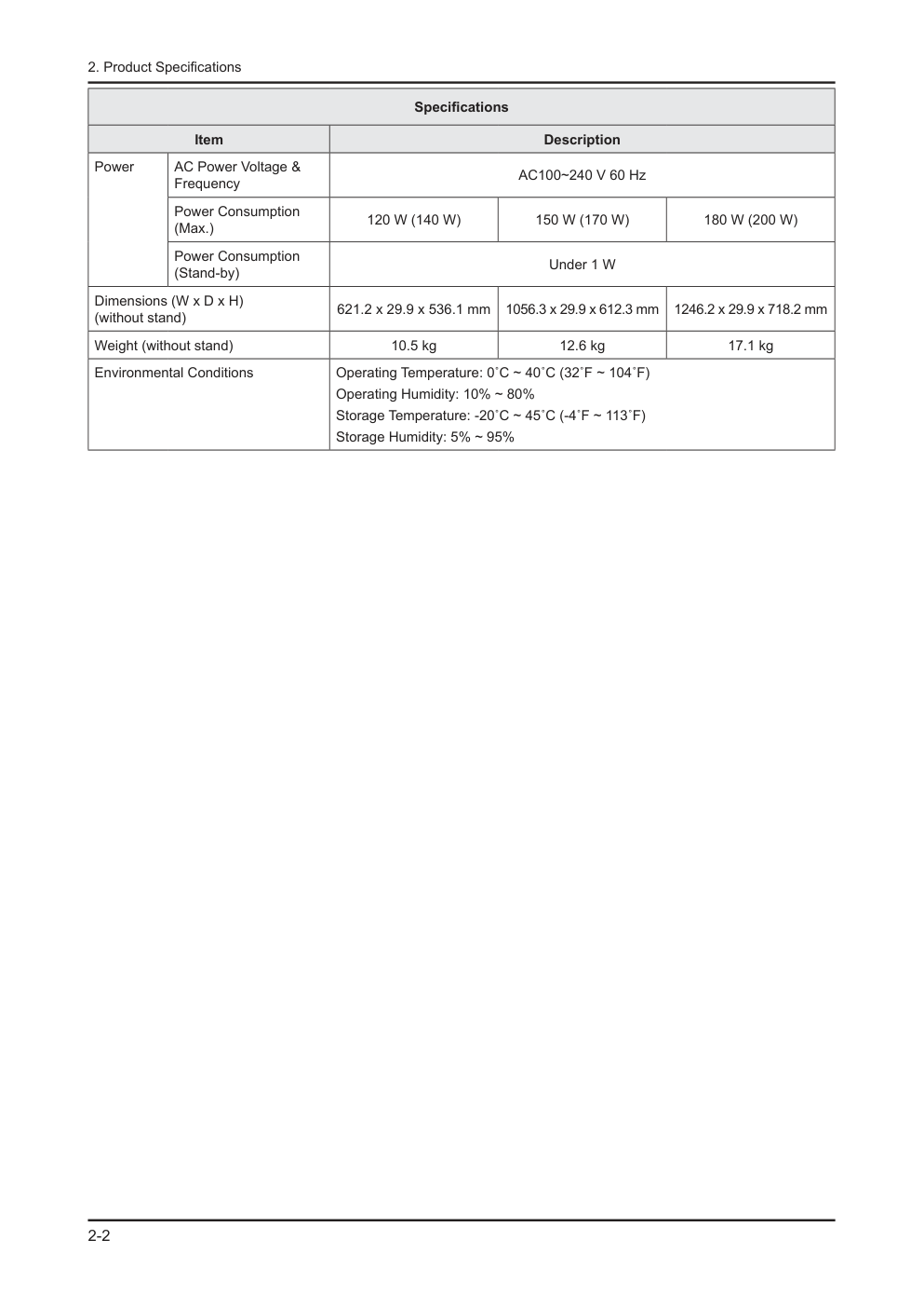
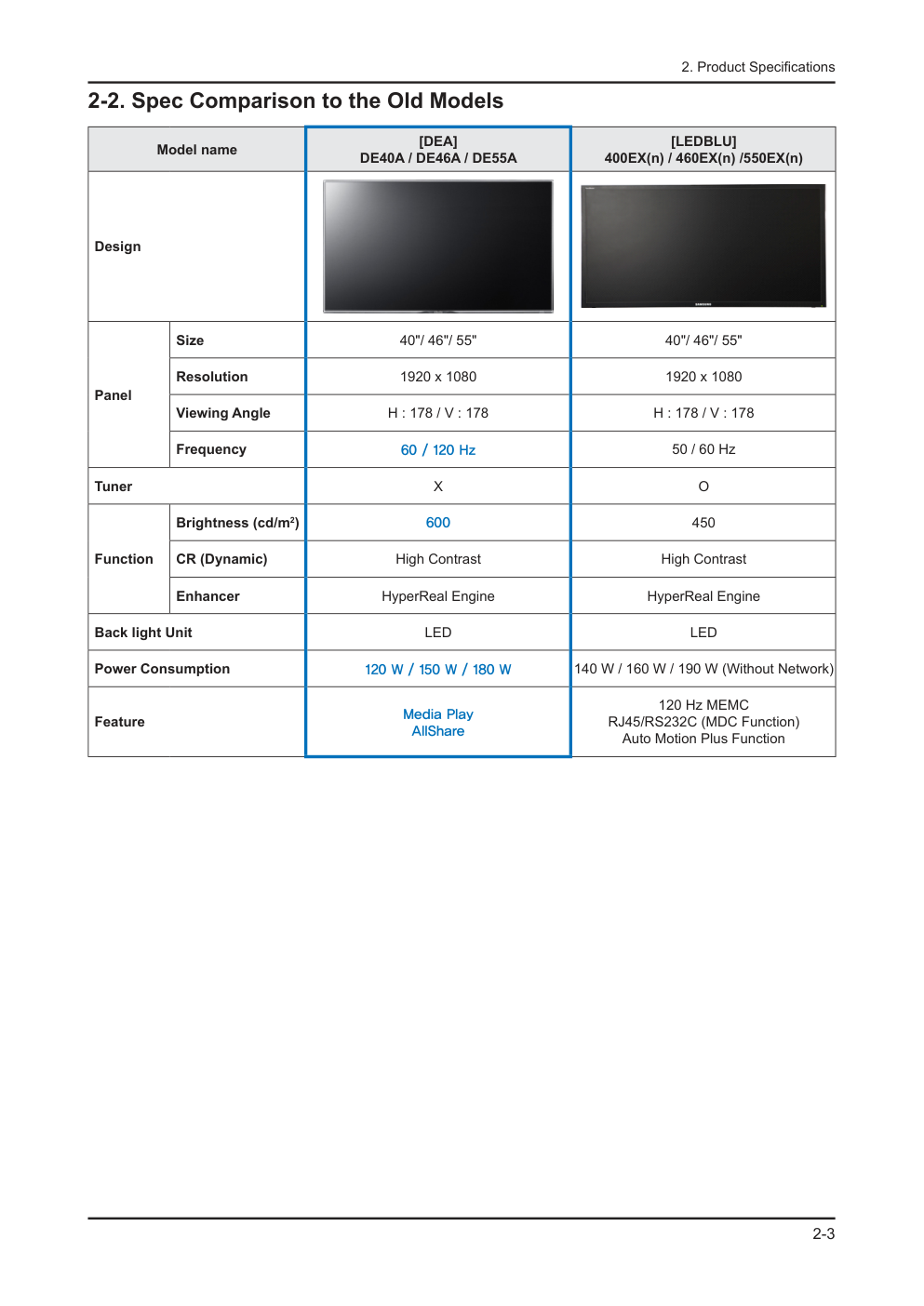
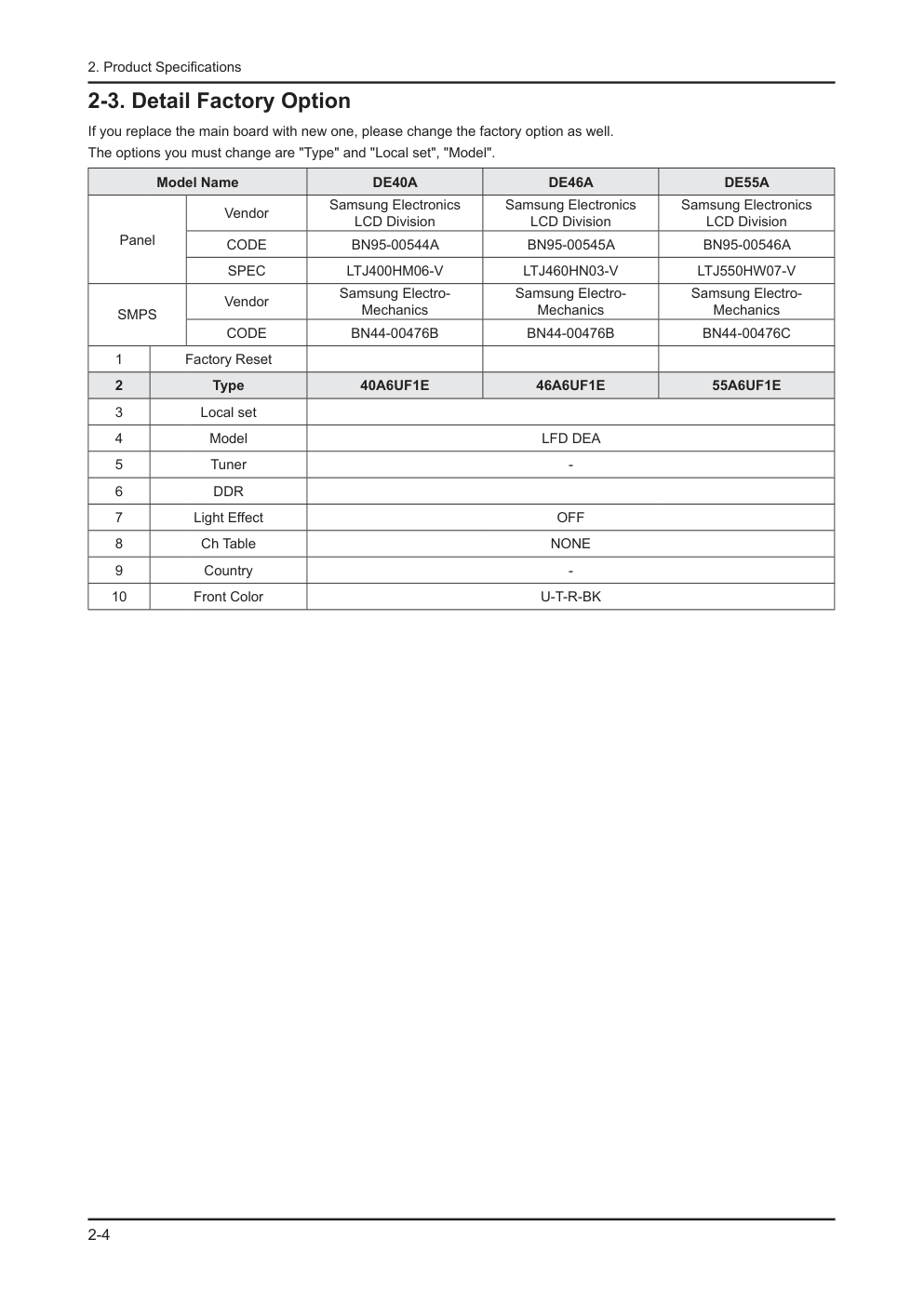
维 修 薄膜 LFD 显示器 目录 DE40A / DE46A / DE55A 1. 注意事项 2. 产品规格 3. 拆卸和重新组装 4. 故障排除 5. 接线图 LFD-显示器 底板 :WDY1 型号 :ME40A ME46A ME55A 型号代码 :LH40DEP***/** LH46DEP***/** LH55DEP***/** 手 册 目录表 1.注意事项 ........................................................................................................................................ 1-1 1-1 安全注意事项........................................................................................................................... 1-1 1-2 维修注意事项........................................................................................................................... 1-2 1-3 静电敏感器件注意事项............................................................................................................. 1-3 1-4 安装注意事项........................................................................................................................... 1-3 2.产品规格 ........................................................................................................................................ 2-1 2-1 特点与规格 .............................................................................................................................. 2-1 2-2 与老型号的规格比较 ................................................................................................................ 2-3 2-3 工厂选项详情.......................................................................................................................... 2-4 2-4 新功能说明 .............................................................................................................................. 2-5 2-5 附件 ....................................................................................................................................... 2-15 3.拆卸和组装..................................................................................................................................... 3-1 3-1 拆卸 ......................................................................................................................................... 3-1 4.故障排除 ........................................................................................................................................ 4-1 4-1 故障排除 ............................................................................................................................. 4-1 4-2 工厂模式调节......................................................................................................................... 4-18 4-3 工厂数据................................................................................................................................ 4-19 4-4 白平衡.................................................................................................................................... 4-36 4-5 软件升级................................................................................................................................ 4-38 4-6 RS-232C ............................................................................................................................... 4-41 4-7 维修项目代码......................................................................................................................... 4-42 5.接线图............................................................................................................................................ 5-1 5-1 接线图...................................................................................................................................... 5-1 5-2 连接器..................................................................................................................................... 5-2 5-3 连接器功能 .............................................................................................................................. 5-6 5-4 接线连接 ................................................................................................................................. 5-6 A-1 分解图和零件清单[DE40A] ..........................................................................................................A-1 A-1-1. 分解图...............................................................................................................................................A-1 A-1-2. 零件清单...........................................................................................................................................A-1 A-2 电气零件清单[DE40A] .................................................................................................................A-2 B-1 分解图和零件清单[DE46A] ...........................................................................................................B-1 B-1-1. 分解图...............................................................................................................................................B-1 B-1-2. 零件清单...........................................................................................................................................B-1 B-2 电气零件清单[DE46A] .................................................................................................................B-2 C-1 分解图和零件清单[DE55A] ...........................................................................................................C-1 C-1-1. 分解图 ..............................................................................................................................................C-1 C-1-2. 零件清单 ..........................................................................................................................................C-1 C-2 电气零件清单[DE55A] .................................................................................................................C-2 本维修手册归三星电子有限公司所有。 未经授权使用该手册可能受到适用的国际和/或国内法律 的惩罚。 © 2011 三星电子有限公司。 版权所有 中国印刷 1-1 1. Precautions 1. Precautions 1-1. Safety Precautions Follow these safety, servicing and ESD precautions to prevent damage and to protect against potential hazards such as electrical shock. 1-1-1. Warnings For continued safety, do not attempt to modify the circuit board. 1. Disconnect the AC power and DC power jack before servicing. 2. 1-1-2. Servicing the LFD Monitor When servicing the LFD Monitor, Disconnect the AC line cord from the AC outlet. 1. It is essential that service technicians have an accurate voltage meter available at all times. Check the calibration of this 2. meter periodically. 1-1-3. Fire and Shock Hazard Before returning the monitor to the user, perform the following safety checks: Inspect each lead dress to make certain that the leads are not pinched or that hardware is not lodged between the 1. chassis and other metal parts in the monitor. Inspect all protective devices such as nonmetallic control knobs, insulating materials, cabinet backs, adjustment and 2. compartment covers or shields, isolation resistorcapacitor networks, mechanical insulators, etc. Leakage Current Hot Check (Figure 1-1): 3. Do not use an isolation transformer during this test. Use a leakage current tester or a metering system that complies with American National Standards Institute (ANSI C101.1, Leakage Current for Appliances), and Underwriters Laboratories (UL Publication UL1410, 59.7). DEVICE UNDER TEST (READING SHOULD) NOT BE ABOVE 0.5mA LEAKAGE CURRENT TESTER TEST ALL EXPOSED METAL SURFACES 2-WIRE CORD *ALSO TEST WITH PLUG REVERSED (USING AC ADAPTER PLUG AS REQUIRED) EARTH GROUND Figure 1-1. Leakage Current Test Circuit With the unit completely reassembled, plug the AC line cord directly into a 120V AC outlet. With the unit’s AC switch first 4. in the ON position and then OFF, measure the current between a known earth ground (metal water pipe, conduit, etc.) and all exposed metal parts, including: metal cabinets, screwheads and control shafts. The current measured should not exceed 0.5 milliamp. Reverse the power-plug prongs in the AC outlet and repeat the test. 1-2 1. Precautions 1-1-4. Product Safety Notices Some electrical and mechanical parts have special safetyrelated characteristics which are often not evident from visual inspection. The protection they give may not be obtained by replacing them with components rated for higher voltage, wattage, etc. Parts that have special safety characteristics are identified by on schematics and parts lists. A substitute replacement that does not have the same safety characteristics as the recommended replacement part might create shock, fire and/or other hazards. Product safety is under review continuously and new instructions are issued whenever appropriate. 1-2. Servicing Precautions An electrolytic capacitor installed with the wrong polarity might explode. Before servicing units covered by this service manual, read and follow the Safety Precautions section of this manual. Note: If unforeseen circumstances create conflict between the following servicing precautions and any of the safety precautions, always follow the safety precautions. 1-2-1. General Servicing Precautions Always unplug the unit’s AC power cord from the AC power source and disconnect the DC Power Jack before attempting 1. to: (a) remove or reinstall any component or assembly, (b) disconnect PCB plugs or connectors, (c) connect a test component in parallel with an electrolytic capacitor. Some components are raised above the printed circuit board for safety. An insulation tube or tape is sometimes used. 2. The internal wiring is sometimes clamped to prevent contact with thermally hot components. Reinstall all such elements to their original position. After servicing, always check that the screws, components and wiring have been correctly reinstalled. Make sure that the 3. area around the serviced part has not been damaged. Check the insulation between the blades of the AC plug and accessible conductive parts (examples: metal panels, input 4. terminals and earphone jacks). Insulation Checking Procedure: Disconnect the power cord from the AC source and turn the power switch ON. 5. Connect an insulation resistance meter (500 V) to theblades of the AC plug. The insulation resistance between each blade of the AC plug and accessible conductive parts (see above) should be greater than 1 megohm. Always connect a test instrument’s ground lead to the instrument chassis ground before connecting the positive lead; 6. always remove the instrument’s ground lead last. 1-3 1. Precautions 1-3. Static Electricity Precautions Some semiconductor (solid state) devices can be easily damaged by static electricity. Such components are commonly called Electrostatically Sensitive Devices (ESD). Examples of typical ESD are integrated circuits and some field-effect transistors. The following techniques will reduce the incidence of component damage caused by static electricity. Immediately before handling any semiconductor components or assemblies, drain the electrostatic charge from your 1. body by touching a known earth ground. Alternatively, wear a discharging wrist-strap device. To avoid a shock hazard, be sure to remove the wrist strap before applying power to the monitor. After removing an ESD-equipped assembly, place it on a conductive surface such as aluminum foil to prevent 2. accumulation of an electrostatic charge. Do not use freon-propelled chemicals. These can generate electrical charges sufficient to damage ESDs. 3. Use only a grounded-tip soldering iron to solder or desolder ESDs. 4. Use only an anti-static solder removal device. Some solder removal devices not classified as “anti-static” can generate 5. electrical charges sufficient to damage ESDs. Do not remove a replacement ESD from its protective package until you are ready to install it. Most replacement ESDs 6. are packaged with leads that are electrically shorted together by conductive foam, aluminum foil or other conductive materials. Immediately before removing the protective material from the leads of a replacement ESD, touch the protective material 7. to the chassis or circuit assembly into which the device will be installed. Be sure no power is applied to the chassis or circuit and observe all other safety precautions. Minimize body motions when handling unpackaged replacement ESDs. Motions such as brushing clothes together, 8. or lifting your foot from a carpeted floor can generate enough static electricity to damage an ESD. 1-4. Installation Precautions For safety reasons, more than a people are required for carrying the product. 1. Keep the power cord away from any heat emitting devices, as a melted covering may cause fire or electric shock. 2. Do not place the product in areas with poor ventilation such as a bookshelf or closet. The increased internal temperature 3. may cause fire. Bend the external antenna cable when connecting it to the product. This is a measure to protect it from being exposed to 4. moisture. Otherwise, it may cause a fire or electric shock. Make sure to turn the power off and unplug the power cord from the outlet before repositioning the product. Also check 5. the antenna cable or the external connectors if they are fully unplugged. Damage to the cord may cause fire or electric shock. Keep the antenna far away from any high-voltage cables and install it firmly. Contact with the highvoltage cable or the 6. antenna falling over may cause fire or electric shock. When installing the product, leave enough space (10cm) between the product and the wall for ventilation purposes. 7. A rise in temperature within the product may cause fire. 2-1 2. Product Specifications 2. Product Specifications 2-1. Feature & Specifications Model DE40A / DE46A / DE55A Feature LFD, HDMI, DP, Component, A/V, USB 2.0 (Media Play), D-SUB, LAN, DVI (In/Out) ሪ Dolby Digital+, SRS Theater HD ሪ High-brightness LCM (600nit) ሪ Anti-glare (AMLCD open cell, Haze 44%) ሪ Specifications Item Description DE40A DE46A DE55A Panel Panel 40" 46" 55" Optimum Resolution 1920 X 1080 Display Size 16 : 9 Picture Engine HyperReal Engine Wide Color Enhancer Plus O Auto Motion Plus 120/240 Hz X (60 Hz) X (60 Hz) O (120 Hz) Brightness 600 cd/m2 Response time (ms) 6 ms View angle (H/V) 178 / 178 Audio Dolby Dolby Digital + SRS SRS TheaterSound HD dts 2.0 + O Sound Output (RMS) 10 W X 2 Speaker Type Down Firing + Full Range Input & Output Audio Out (Mini Jack) 1 Component In (Y/Pb/Pr) 1 Composite In (AV) 1 Common Use for Component Y DVI Audio In (Mini Jack) 1 Common Use for PC Audio in Ethernet (LAN) 1 HDMI Input 1 DVI Input 1 DVI Loopout 1 PC Audio In (Mini Jack) 1 PC In (D-sub) 1 RS232C (MDC CONTROL) 1 USB 1 2-2 2. Product Specifications Specifications Item Description Power AC Power Voltage & Frequency AC100~240 V 60 Hz Power Consumption (Max.) 120 W (140 W) 150 W (170 W) 180 W (200 W) Power Consumption (Stand-by) Under 1 W Dimensions (W x D x H) (without stand) 621.2 x 29.9 x 536.1 mm 1056.3 x 29.9 x 612.3 mm 1246.2 x 29.9 x 718.2 mm Weight (without stand) 10.5 kg 12.6 kg 17.1 kg Environmental Conditions Operating Temperature: 0˚C ~ 40˚C (32˚F ~ 104˚F) Operating Humidity: 10% ~ 80% Storage Temperature: -20˚C ~ 45˚C (-4˚F ~ 113˚F) Storage Humidity: 5% ~ 95% 2-3 2. Product Specifications 2-2. Spec Comparison to the Old Models Model name [DEA] DE40A / DE46A / DE55A [LEDBLU] 400EX(n) / 460EX(n) /550EX(n) Design Panel Size 40"/ 46"/ 55" 40"/ 46"/ 55" Resolution 1920 x 1080 1920 x 1080 Viewing Angle H : 178 / V : 178 H : 178 / V : 178 Frequency 60 / 120 Hz 50 / 60 Hz Tuner X O Function Brightness (cd/m2) 600 450 CR (Dynamic) High Contrast High Contrast Enhancer HyperReal Engine HyperReal Engine Back light Unit LED LED Power Consumption 120 W / 150 W / 180 W 140 W / 160 W / 190 W (Without Network) Feature Media Play AllShare 120 Hz MEMC RJ45/RS232C (MDC Function) Auto Motion Plus Function 2-4 2. Product Specifications 2-3. Detail Factory Option If you replace the main board with new one, please change the factory option as well. The options you must change are "Type" and "Local set", "Model". Model Name DE40A DE46A DE55A Panel Vendor Samsung Electronics LCD Division Samsung Electronics LCD Division Samsung Electronics LCD Division CODE BN95-00544A BN95-00545A BN95-00546A SPEC LTJ400HM06-V LTJ460HN03-V LTJ550HW07-V SMPS Vendor Samsung Electro- Mechanics Samsung Electro- Mechanics Samsung Electro- Mechanics CODE BN44-00476B BN44-00476B BN44-00476C 1 Factory Reset 2 Type 40A6UF1E 46A6UF1E 55A6UF1E 3 Local set 4 Model LFD DEA 5 Tuner - 6 DDR 7 Light Effect OFF 8 Ch Table NONE 9 Country - 10 Front Color U-T-R-BK 2-5 2. Product Specifications 2-4. New Functions 2-4-1. Eco Solution Menu → System → Eco Solution → ENTER The display may differ depending on the product model. 1. Energy Saving Off / Low / Medium / High / Picture Off ሪ You can reduce the product's power consumption by adjusting the screen brightness. When Picture Off is selected, the audio will remain on even if the screen turns off. To turn the screen back on, press any button other than the volume button. 2. Eco Sensor Off / On ሪ The brightness can automatically be adjusted according to the ambient light intensity. Adjusting the Backlight / Cell Light settings when the eco sensor is turned on will turn off the eco sensor. N Min Backlight: Adjust the minimum backlight when the eco sensor is turned on. - The Min Backlight option can be used to adjust the backlight intensity when the screen is darkest. Ensure the Min N Backlight value is smaller than the Backlight value. The display brightness may change according to the ambient light intensity. (The display becomes slightly darker N or brighter.) 3. No Signal Power Off Off / 15 min / 30 min / 60 min ሪ This option turns off the power automatically if no input source is detected for a specified period of time. This function does not activate if the PC is in power-saving mode. N 4. Auto Power Off Off / On ሪ This option automatically powers off the product to prevent overheating if the product remains idle for 4 hours. 2-6 2. Product Specifications 2-4-2. Media Menu → Media → ENTER The display may differ depending on the product model. MagicInfo Lite MagicInfo Lite Player Guide MagicInfo Lite Player allows you to play content (image, video, document files) at a desired time. You can play content saved in internal memory or USB memory. You can also play content via MagicInfo Lite Server after connecting to a network. For further details about how to use MagicInfo Lite Server, refer to the MagicInfo Lite Server user manual. N Image files in .jpg format can only be played. PowerPoint files for MS Office 2007 or lower are only supported. N (Note that PowerPoint files for MS Office 2007 or lower may not be compatible.) Quick Menus You can change the Picture Mode or Sound Mode setting or safely remove a USB device while content is playing by pressing TOOLS on the remote control. Picture Mode: Customize the screen settings for the content currently playing. (Dynamic, Standard, Natural, Movie) - Sound Mode: Customize the audio settings for the content currently playing. (Standard, Movie, Music, Clear Voice, - Amplify) Safely Remove USB - Viewing Information Software Version: Display the software version of a device. 1. Device Name: Display the name of a device recognized by the server. 2. Device ID: Display the original identification number of a device. 3. Mode: Display the current operating mode (Network Schedule, Local Schedule, Internal AutoPlay or USB AutoPlay) of 4. MagicInfo Lite Player. Server: Display the status of the connection to the server (Connected, Disconnected or Non-Approval). 5. USB: Display the status of the connection to a USB device. 6. Schedule download: Display the progress of a network schedule being downloaded from the server. 7. 2-7 2. Product Specifications Videos Connecting to a USB Device Power on the product. 1. Connect a USB device that contains photo, music or video files to a USB port on the product. 2. A window will appear. Select the connected USB device in the window. 3. Playing a Video l 1. / r / u / d to select a file from the list of files. Press ENTER or 2. � (Play). The selected file will be displayed along with the playing time at the top. - If the video time information is not available, the playing time and progress bar will not appear. - To navigate scenes during video playback, press - l or r. The [ - �] (REW) and [μ] (FF) buttons are available for use during playback. To close the video playback, press RETURN. - Supported Subtitle Formats Item File extension Format MPEG-4 time-based text .ttxt XML SAMI .smi HTML SubRip .srt String-based SubViewer .sub String-based Micro DVD .sub or .txt String-based Supported Video Formats File extension Container Video codec Resolution Frame rate (fps) Bit rate (Mbps) Audio codec *.avi *.mkv AVI MKV Divx 3.11/4.x/5.1/6.0 1920 x 1080 6 ~ 30 8 MP3/AC3/LPCM/ ADPCM/DTS Core XviD 1920 x 1080 6 ~ 30 8 H.264 BP/MP/HP 1920 x 1080 6 ~ 30 25 MPEG4 SP/ASP 1920 x 1080 6 ~ 30 8 Motion JPEG 640 x 480 6 ~ 30 8 *.asf ASF Divx 3.11/4.x/5.1/6.0 1920 x 1080 6 ~ 30 8 MP3/AC3/LPCM/ ADPCM/WMA XviD 1920 x 1080 6 ~ 30 8 H.264 BP/MP/HP 1920 x 1080 6 ~ 30 25 MPEG4 SP/ASP 1920 x 1080 6 ~ 30 8 Motion JPEG 640 x 480 6 ~ 30 8 *.wmv ASF Windows Media Video v9 1920 x 1080 6 ~ 30 25 WMA *.mp4 MP4 H.264 BP/MP/HP 1920 x 1080 6 ~ 30 25 MP3/ADPCM /AAC MPEG4 SP/ASP 1920 x 1080 6 ~ 30 8 XVID 1920 x 1080 6 ~ 30 8 *.3gp 3GPP H.264 BP/MP/HP 1920 x 1080 6 ~ 30 25 ADPCM/AAC/HE- AAC MPEG4 SP/ASP 1920 x 1080 6 ~ 30 8 *.vro VRO VOB MPEG2 1920 x 1080 24/25/30 30 AC3/MPEG/LPCM MPEG1 1920 x 1080 24/25/30 30 *.mpg *.mpeg PS MPEG1 1920 x 1080 24/25/30 30 AC3/MPEG/LPCM/ AAC MPEG2 1920 x 1080 24/25/30 30 H.264 1920 x 1080 6 ~ 30 25 *.ts *.tp *.trp TS MPEG2 1920 x 1080 24/25/30 30 AC3/AAC/MP3/ DD+/HE-AAC H.264 1920 x 1080 6 ~ 30 25 VC1 1920 x 1080 6 ~ 30 25 2-8 2. Product Specifications The codec does not work with faulty content files even if the files are codec compatible. N Audio or video of content will not be available if the standard bit rate or frame rate is higher than the frame rate per N second specified in the table above. The search (skip) function will not be available if there is any error in the index table. N If playing a video file over a network connection, the file may not play smoothly. N Displaying a menu will take longer than usual if the bit rate of a video file exceeds 10 Mbps. N Some USB devices and digital cameras may not be compatible with the player. N Video Decoder Audio Decoder H.264 level 4.1 or lower is supported. • H.264 FMO/ASO/RS, VC1 SP/MP/AP L4, and AVCHD • are not supported. XVID, MPEG4 SP, ASP: • 1280 x 720 or smaller: Max. 60 frames - 1280 x 720 or greater: Max. 30 frames - GMC 2 or higher is not supported. • WMA 7, 8, 9 STD or lower is supported. • WMA 9 PRO does not support lossless audio or multi- • channel audio higher than 2 channels. A WMA sampling rate of 22050 Hz mono is not • supported. RealAudio 10 lossless is not supported. • Photos Connecting to a USB Device Power on the product. 1. Connect a USB device that contains photo, music or video files to a USB port on the product. 2. A window will appear. Select the connected USB device in the window. 3. Viewing Photos (or a Slideshow) l 1. / r / u / d to select a file from the list of files. Press ENTER. 2. To start a slideshow immediately, press the - � (Play) button in the screen of the list of files. All the files included in the list of files will be used for the slideshow. - If the background music is enabled, a music file can be played during a slideshow. N The background-music setting cannot be changed until the background-music file is completely loaded. N Music Connecting to a USB Device 1. Power on the product. 2. Connect a USB device that contains photo, music or video files to the USB port on the product. 3. A window will appear. Select the connected USB device in the window. Playing Music 1. Press l / r / u / d to select a music file from the list of files. 2. Press ENTER or � (Play). To navigate music files when playing music, press [ - �] (REW) or [μ] (FF). Only files with MP3 or PCM extensions will be displayed. Files with extensions other than MP3 or PCM will not be N displayed even if they are saved on the same USB device. If you find the audio strange when playing an MP3 file, adjust the equalizer in the audio menu. (An over- N modulated MP3 file can cause an audio problem.) 2-9 2. Product Specifications Videos / Photos / Music - Additional Functions Sorting a File List Menu Function Videos Photos Music Folder view Display all the folders. To view file names and thumbnail images, select a folder. c c c Title Sort and display file names in the order of symbols, numbers, text, or special characters. c c c Latest Date Sort and display files by time modified, latest to earliest. c c Earliest Date Sort and display files by time modified, earliest to latest. c c Monthly Sort and display photo files by month. c Artist Sort music files by artist name. c Album Sort music files by album name. c Genre Sort music files by genre. c Options Available During Video / Photo / Music Playback You can use the following functions when playing a video or viewing a slideshow by pressing TOOLS. Menu Function Videos Photos Music List Return to the list of files. c c c Play / Pause Play a file or pause the file playback. Alternatively, use the play or pause button on the remote control. c c Previous / Next Move to the previous or next photo file. c Random Play music in regular or random order. c Play Continuously Start playing a recording from the last playback point. c Scene Search Navigate scenes that are divided into five chapters. c Title Search Search and play another video using the title. c Time Search Navigate a video at one-minute intervals by pressing the l or r button. c Subtitle Display subtitles. You can select a language if the subtitle file contains more than one language. c Repeat Mode Play a video or music file repeatedly. c c Size Customize the display size. c Picture Mode Change the display mode. c c Sound Mode Change the audio mode. c c c Audio Language Play a video in the language you want. This option is enabled only when playing a streaming file that supports the multi-audio format. c Subtitle Setting Display the subtitle settings menu and configure the subtitle settings. c Start / Stop Slide Show Start or stop a slideshow. c Slide Show Speed Specify the slideshow speed during a slideshow. Alternatively, use the � (REW) or μ (FF) button. c Slide Show Effect Insert various slideshow effects. c Background Music On / Off Start or stop playing background music. c Background Music Setting Enable and specify the background music when viewing photo files or a slideshow. c Zoom Enlarge an image to display it in full-screen mode. c Rotate Rotate an image. c To view information on a device, select the device name and press INFO. N To view information on a file, select the file and press INFO. N 2-10 2. Product Specifications Source Source allows you to select a variety of input sources and change source-device names. You can display the screen of a source device connected to the product by selecting the corresponding input source from the list of input sources. After connecting a source device, press SOURCE on the remote control and select the connected source device. N The screen may not display correctly if an incorrect source is selected for the source device you want to convert to. N Edit Name You can specify the name of a connected source device. Sometimes the screen will not display properly unless the name of a source device is specified in Edit Name. - To obtain optimal picture quality, specify the name of the source device in Edit Name. The list of input sources can include the following source devices. Source devices in the list can vary depending N on the input source selected. - VCR / DVD / Cable Set-top Box / HD STB / Satellite STB / PVR Set-top Box / Source Receiver / Game / Camcorder / PC / DVI PC / DVI Devices / Blu-ray / HD DVD / DMA Available settings in the Picture menu depend on the current source and settings made in Edit Name. - If the HDMI IN port on the product is connected to a PC using an HDMI cable, go to Edit Name and change the input - source to PC. If the HDMI IN port on the product is connected to a PC using an HDMI/DVI cable, go to Edit Name and change the - input source to DVI PC. If the HDMI IN port on the product is connected to an Source device using an HDMI/DVI cable, go to Edit Name and - change the input source to DVI Devices. Information You can view the details of a connected source device by selecting it from the list of source devices and pressing TOOLS. Device search If the source device connected is not enabled in the Source screen, press TOOLS. The source device will be searched for. AllShare AllShare allows you to connect a compatible Samsung mobile device (cell phone, etc.) to the product over a network. Incoming phone calls or text messages and schedules on your cell phone can be viewed on the product screen. Also, media content (video, photo or music files) saved on your cell phone or PC can be played on the product. The product can also be used to navigate web pages on your cell phone. For further details, visit "www.samsung.com/sec" or contact the Samsung customer service center. Additional N software may need to be installed on your mobile device. For details, refer to the user's manual for the mobile device. If a Samsung product connects to a non-Samsung DLNA server, a compatibility issue may occur during video N playback. By connecting a Samsung product to a network through AllShare, you can use Samsung's original functions as N follows: Playback of various video formats (DivX,XVID, MP4, 3GPP, AVI, ASF, MKV, etc.) • Video thumbnail feature • Bookmark function (to resume video playback) • Auto-chaptering (scene navigation) • Digital content management • Compatibility with various subtitle formats (SRT, SMI, SUB, TXT, TTXT) • Search with file names • And many others • To use the original DLNA functions of Samsung fully, it is recommended that you use the AllShare software provided N with the product. 2-11 2. Product Specifications 2-4-3. Network Menu → Network → ENTER The display may differ depending on the product model. Network Settings Connecting to a Wired Network You can connect the product to the Internet through a wired connection with a LAN cable using one of the following three methods. To use an external modem, connect the cables as shown below. - RJ45 The Modem Port on the Wall External Modem (ADSL / VDSL) elb a C N A L elb a C m e d o M LAN To use an external modem and an IP router, connect the cables as shown below. - The Modem Port on the Wall External Modem (ADSL / VDSL) IP Sharer (having DHCP server) LAN Modem Cable LAN Cable LAN Cable RJ45 2-12 2. Product Specifications To connect directly to a LAN port on a wall, connect the cable as shown below. - The LAN Port on the Wall LAN LAN Cable RJ45 To use a dynamic network, an ADSL modem or router that supports Dynamic Host Configuration Protocol (DHCP) - must be used. A modem or router that supports DHCP automatically assigns the IP address, subnet mask, gateway and DNS that are needed to connect the product to the Internet. You are not required to enter them manually. Most of the home-use networks are dynamic. Some networks require static IP addresses. To use a network that needs a static IP address, you must manually specify the IP address, subnet mask, gateway and DNS using the Cable Setup menu on the product. For your IP address, subnet mask, gate and DNS, contact your Internet service provider. You can view them on your PC if the PC is Windows based. If using a network that requires a static IP address, you can use an ADSL modem that supports DHCP. You can N use a static IP address through the ADSL modem that supports DHCP. Wired Network Setup By connecting the product to a network, you can upgrade software and use various Internet services (Smart Hub, AllShare, etc.). Automatic network setup ሪ You can connect the product to a network using a LAN cable. Make sure that the LAN cable is connected. Manual network setup ሪ A static IP is used in some environments such as offices. In such a case, you need to ask the network administrator for the IP address, subnet mask, gateway and DNS server address and manually enter them. Wireless Network Connection You can access the Internet by connecting the product to a wireless Internet router using a Samsung wireless LAN adapter (WIS09ABGN, WIS09ABGN2 or WIS10ABGN). The LAN Port on the Wall Wireless IP sharer (router having DHCP server) LAN Cable Product Rear Panel Samsung Wireles LAN Adapter A Samsung wireless LAN adapter can be purchased separately from the Samsung customer service center (1588- 3366) or at your nearest Samsung retailer. A Samsung wireless LAN adapter supports an 802.11a/b/ g/n wireless communication protocol. Samsung recommends that you use IEEE 802.11n. If playing a video file over a network connection, the file may not play smoothly. To access the Internet through a wireless connection, you must connect the product to a wireless IP router (or N modem) using a Samsung wireless LAN adapter (WIS09ABGN, WIS09ABGN2 or WIS10ABGN). If the wireless IP router supports DHCP, you can connect the product to the Internet using an automatic or static IP address. It is recommended that you connect the Samsung wireless LAN adapter to the USB 2 (HDD) port. If the adapter is N connected to the USB 1 port, the Internet connection may not work properly depending on the network condition. In regards to the channel of the wireless IP router, do not select a channel that is being used by another device. If a N channel used by a nearby device is selected, communication failure or interference may occur. If using a security system other than the AP encoding formats specified below, the product will not connect to a N network. If 802.11n mode is selected for pure high-throughput (Greenfield) and the AP encoding format is set to WEP, TKIP • or TKIP AES (WPS2Mixed), the product cannot connect to a network using Wi-Fi. 2-13 2. Product Specifications If your wireless router supports Wi-Fi Protected Setup (WPS), you can connect to a network through Push Button N Configuration (PBC) or a Personal Identification Number (PIN). WPS automatically configures the SSID and WPA keys in both the PBC and PIN modes. If your wireless IP router is not certified, it cannot connect to the product through the "Samsung wireless LAN adapter." N Ensure the product is powered off when you connect the Samsung wireless LAN adapter to the product. N How to connect: You can configure the wireless network settings using one of the following five methods. N Auto setup (using the auto network search function) • Manual setup • WPS (PBC) • One Foot Connection • If the product is connected to a wireless network using a USB cable other than the cable provided or through a USB N hub, the Samsung wireless LAN adapter may not be recognized. Wireless Network Setup Automatic network setup ሪ If a security key (PIN or password) is assigned to the wireless router, the security key must be entered. If using wireless Internet service, ask the service provider for the security key. Manual network setup ሪ A static IP is used in some environments such as offices. In such a case, you need to ask the network administrator for the IP address, subnet mask, gateway and DNS server address and manually enter them. Network Setup WPC (PBC) ሪ A connection can be established only when the wireless router has a WPS (PBC) button. One Foot Connection ሪ One Foot Connection allows you to easily connect to the Internet by placing the Samsung wireless router within a distance of 25 cm from the product. Ad Hoc ሪ A connection can be established only when the device to be connected supports Ad Hoc. Network Status View the current status of the connection to the network and Internet. AllShare Settings Media (Off / On): Enable or disable the Media function. By enabling the Media function, you can control media - content using another device (cell phone, etc.) that supports DLAN DMC. Media You can view a list of connected devices (cell phone, etc.) that are set on the product as devices that have access to the Media function. The Media function can be used on a mobile device that supports DLNA DMC. N Allowed / Denied: Allow or block a device. • Delete: Delete a device from a list of devices. • This option deletes only a mobile device name from the list of devices. The device will display again on the list when N the device is turned on or connected to the product. 2-14 2. Product Specifications MagicInfo Lite Settings 1. Server Configuring the MagicInfo Lite server IP - Enter the server IP address and port number. (Use 7001 as the port number. If unable to connect to the server • using port number 7001, check with your server administrator to find the correct port number and then change the port number.) FTP Mode - Configure the FTP operating mode. (Active or Passive) • Default Storage - Specify the default memory to save schedules or content sent from the server to. • When the default storage space is set to USB, a schedule will not run if a USB device is not connected. • Send a notification message to the server when internal memory is used up. • 2. Storage Internal Memory: Display the space currently being used, or delete all content. - USB: Display the space currently being used. - 3. Slideshow Image Viewer Time: Specify the length of time each image is displayed for a local schedule or slideshow. - PPT Viewer Time: Specify the length of time each document page is displayed for a local schedule or slideshow. - Image Effect: Configure the image transition effects. - Fade1, Fade2, Blind, Spiral, Checker, Linear, Linear, Wipe, Random, None • 4. Schedule Name Select a schedule title format when creating a local schedule: - YYYYMMDD, YYYYDDMM or DDMMYYYY • 5. Safely Remove USB You can safely remove USB memory. - 6. Information Device Name: Display the name of a device recognized by the server. - Serial Number: Display the original identification number of a device. - Software Version: Display the software version of a device. - 2-15 2. Product Specifications 2-5. Accessories Product Description Code. No Remark Quick setup guide BN68-03728B Samsung Electronics Service Center Warranty card (Not available in all locations) BH68-00633B User manual BN46-00098B MagicInfo Lite Edition Software CD BN46-00097B Cleaning cloth BN63-01798B Power cord 3903-000525 POWER OFF SOURCE GUIDE INFO EXIT RETURN TOOLS MENU TTX/MIX MagicInfo AA59-00539A MTS/DUAL 1 2 3 4 5 6 7 8 9 - 0 PRE-CH .QZ ABC DEF GHI JKL MNO PRS TUV WXY SYMBOL ENTER DEL -/-- MUTE VOL CH/P MagicInfo AUTO LOCK MDC I-II PC DP DVI HDMI A B C D Lite CH LIST Remote Control AA59-00539A + + - - Batteries (Not available in all locations) 4301-000103 D-SUB cable BN39-00244H RS232C Adapter BN39-01545A 2-16 2. Product Specifications Product Description Code. No Remark AV/Component Adapter BN39-01154W Samsung Electronics Service Center Holder-Wire stand BN61-05491A Holder-Ring (4EA) BN96-18153A 3 拆卸和重新组装 3-1 3.拆卸和重新组装 维修手册的这一章叙述本显示器的拆卸和重新组装步骤。 警告:本显示器包含静电敏感器件,处理这些部件时应小心。 3-1.拆卸 小心:1.为了便于重新安装,在水平面上放置显示器并进行拆卸。 2.在显示器下铺一块软布,以防屏幕划伤。 3. 在拆卸机体前要先将信号线缆和电源线卸下。 说明 图片 1.拆卸后盖上的 8 个螺钉。 螺钉 2.将后盖提起并卸下。 3 拆卸和重新组装 3-2 说明 图片 3.拆卸中盖上的 10 个螺钉。 螺钉 4.提起中盖并将其卸下。 5.拆卸扬声器(左/右)。 3 拆卸和重新组装 3-3 说明 图片 6.拆卸主板上的螺钉。 螺钉 注意:在拆卸板前,断开所有接线连 接器。 7.拆卸 IP 板上的螺钉。 螺钉 3 拆卸和重新组装 3-4 说明 图片 8.拆卸 T-CON 机架上的螺钉。 螺钉 9. 40”/46”/55”屏板。 ※ 重新组装步骤与拆卸步骤相反。 4. 故障排除 4-1 转换板 主板 SMPS 板 扬声器(右侧) T-Con 板 扬声器(左侧) 4.故障排除 4-1.故障排除 4-1-1.预前检查 1. 首先检查各电缆连接情况。 检查是否烧坏或损坏的接线。 检查接线是否断开,或连接处太松。 检查是否依据连接图连接接线。 2. 检查主板的电源输入。 3. 如何辨别故障是否由主板或 T-Con 板引起的。 -无图像:如果发生的故障是没有图像,但是 BLU 处于开启状态,LED 指示灯不断闪烁,更换 T-con 板。 -图像失真:检查内部图形。 � 对于所有模式 内部图案 Napoli Pre Napoli post 图片 故障 很好 很好 很好 不正常 主板或信号源 不正常 很好 很好 不正常 主板 不正常 不正常 很好 不正常 主板或 FRC 设置 不正常 不正常 不正常 不正常 主板或 LVDS 接线或 T-con 或屏板。 � 仅适用于 HDMI 模式(附加检查) HDMI 图片 故障 很好 不正常 检查 HDMI IC 上的 HDMI 来源或 HDMI 插孔后没有问题。 不正常 不正常 检查 HDMI IC 上的 GenoaS 图形或 LVDS 接线或 T-con 前没有问题。 � 如何检查内部图案? 1. 工厂模式(静音→1 → 8 → 2 → 开机当显示器处于“待机”模式) 2. 移动到SVC菜单。 3. 移动到测试图。 4. 检查内部图案。 (本型号仅支持FBE、READ PRE、READ POST) 4.故障排除 4-2 � 简单的故障流程图 电视是否打开? 显示屏上是否有在 屏显示调节菜单? 是否可以看到数字 信道广播。 屏幕是否有显示? 否 否 检查电源线 检查连接到主板上的 LVCD 接线。必要时,可 更换主板。 更换主板 请联系技术支持部门。 是 是 是 是 否 否 4. 故障排除 4-3 主板 4.故障排除 4-4 4-1-2.如何检查故障症状 � 未通电 • 参看下一页可检查维修手册中所提到的如 CN201 或 IC201 部件所在的位置。 征兆 -当连接电源线时,前显示屏上的 LED 指示灯未工作。 -当连接电源线时,SMPS 继电器未工作。 -本机似乎损坏。 主要检查点 如果接线连接不当或主板或 SMPS 有故障,当连接电源线时,IP 继电器或前部屏板 LED 不工作。在这种情况下,检查下列各项: -检查本机内部接线连接状态。 -检查各零件的保险丝。 -检查 SMPS 的输出电压。 -更换主板。 诊断 小心 在 IP 板上工作之前,必须断电。 否 当未接入 28p 接线时,检查背景灯是否 开启? 是 CN201 的管脚 4 上是否出现正常的待机 DC A5V 电压? 是 检查“主板电源的输入”是否正常? - PIN7:B18VS - PIN11:B13V - PIN1:B5V 是 IC1210 的管脚 3 上是否出现正常的 DC A3.3V 电压? 否 是 否 更换 28p 接线。 更换主板电源组件。 在 IC202 的管脚 8 上是否出现正常的 DC B3.3V,IC201 管脚 3 上出现正常的 B9V? 是 C1009,C1035 上是否出现正常的 Genoa-P core 3.3V,1.1V? 否 更换 IC202,IC207 或主板组件。 否 否 是 检查为 C228 的屏板提供电源,是否出现 在 C228 上? 否 检查其它功能(无图像部分) 更换 LCD 屏板。 检查电源线的连接情况。 当电源开通时,检查继电器的声音是否 开启? 是 否 更换 IC202,IC201 或主板组件 更换 IC1210 或主板组件 4. 故障排除 4-5 定位(主板) 详情 4.故障排除 4-6 � 无图像(模拟 PC 信号) • 参看下一页可检查维修手册中所提到的如 CN401 或 IC801 部件所在的位置。 征兆 -声音正常,但屏幕上未显示画面。 主要检查点 -检查PC来源 -检查Arsenal,并检查Valencia。 -当LVDS接线连接到主板及屏板被断开的情况下可能会发生。 诊断 小心 在 IP 板上工作之前,必须断电。 否 输入正常的模拟 PC 信号,检查连 接接线。 否 更换PC接线。 更换主板组件。 检查 PC 来源,并检查 DSUB 接线的 连接情况? 是 否 更换 IC801 或更换主板组件。 检查 1,2,3,13,14(R、G、B、H、V) 是否有信号出现? 是 检查 IC801 上是否有数字输出? � � 否 请与技术支持部联系。 是 检查LVDS接线? 更换液晶显示屏? 4. 故障排除 4-7 定位(主板) 详情 4.故障排除 4-8 � 波形 �PC输入 (竖直同步,水平同步,R/G/B) �LVDS输出 4. 故障排除 4-9 � 没有图像(HDMI-数字信号) 参看下一页可检查维修手册中所提到的如 CN1502 或 IC1202 部件所在的位置。 小心 在 IP 板上工作之前,必须断电。 征兆 -声音正常,但屏幕上未显示画面。 主要检查点 -检查HDMI来源 -检查HDMI切换,检查Valencia -当LVDS接线连接到主板及屏板被断开的情况下可能会发生。 诊断 否 输入正确的 HDMI 信号。 电源指示灯关闭。 灯(背景灯)打开,是否有图像? 是 否 首先,检查外部设备的设置情况。然后 检查 HDMI 接线。如果故障仍然存在, 更换主板。 检查 HDMI 来源,并检查 HDMI 接 线的连接情况? 是 否 更换 IC1202 或更换主板组件。 IC601 管脚 11~18(HDMI)上是否有信 号出现? 是 检查 CN1502 管脚 14~42 的输出 上是否有数字数据? 否 是 检查 LVDS 接线? 检查 T-con 板? 更换液晶显示屏? � � � 否 在“待机模式”中检查机体。 请与技术支持部联系。 4.故障排除 4-10 定位(主板) 详情 4. 故障排除 4-11 � 波形 �PC输入 (竖直同步,水平同步,R/G/B) �LVDS输出 4.故障排除 4-12 � 没有图像(分量) 参看下一页可检查维修手册中所提到的如 CN1502 或 IC1202 部件所在的位置。 征兆 -声音正常,但屏幕上未显示画面。 主要检查点 -检查分量来源。 -检查Valencia。 -当LVDS接线连接到主板及屏板被断开的情况下可能会发生。 小心 在PD板上工作之前,必须断电。 诊断 小心 在 IP 板上工作之前,必须断电。 否 在“待机模式”中检查机体。 电源指示灯关闭。 灯(背景灯)打开,是否有图像? 是 否 输入正确的分量源信号。 检查 HDMI 来源,并检查分量接线 (Y,Pb,Pr)的连接情况? 是 否 更换 CN404 或主板组件。 R438、R439、R437(Y, Pb, Pr) 是否有信号出现? 是 CN1502 管脚 14~42 是否有数字数据出现? � � 否 更换 IC1202 或主板组件。 是 检查 LVDS 接线? 检查 T-con 板? 更换液晶显示屏? 否 请与技术支持部联系。 4. 故障排除 4-13 定位(主板) 详情 4.故障排除 4-14 � 波形 �分量_Y (Gray scale) / Pb / Pr (彩色条) �LVDS输出 4. 故障排除 4-15 否 检查CN404、CN402 更换主板组件。 检查声音来源,并检查声音接线的连接情 况(Comp/PC/DVI 到 HDMI)? 是 否 检查IC302、IC1202。 更换主板组件。 检查主板上否有信号出现? COMP, AV R:C414 / L:C412 PC、DVI R:C408 / L:C409 是 否 检查IC302、IC1202。 更换主板组件。 在音频 IC 上检查 12C DATA 是否正常? IC302 管脚#1:MCLK IC302 管脚#5:Data 是 1. 检查扬声器的声音数据是否正常? (tp R+/-、tp L+/-) 2. 检查显示器的声音数据是否正常? (tp monitor_R、tp monitor_L) � � 否 请与技术支持部联系。。 是 更换扬声器? 否 输入正常的声音来源。 � 没有声音(扬声器) 参看下一页可检查维修手册中所提到的如CN404或IC302部件所在的位置。 征兆 -视频正常,但没有声音。 主要检查点 -当扬声器连接断开或损坏时 -当主板的声音处理部分失去功能时 -扬声器损坏。 诊断 小心 在 IP 板上工作之前,必须断电。 4.故障排除 4-16 定位(主板) 详情 4. 故障排除 4-17 � 波形 � MCLK / LRCLK / PCM_I2C_DATA �扬声器/显示器输入,SPDIF输出 4 故障排除 4-18 4-2.工厂模式调节 4-2-1 进入工厂模式 如欲进入“维修模式”,可按下列顺序按下遥控键: -如果没有工厂遥控器 关机 静音 开机 -如果你有工厂遥控器 信息 工厂 一些项目没有工厂遥控器将不能使用。 4 故障排除 4-19 4-3.工厂数据 4-20 4. Troubleshooting Control Factory Menu Name Data Range Remark 24Px4 Support OFF Power Indicator Support ON BD Wise Support ON Data Service Support ... PVR Support ... 3D Support 2D Gemstar Support OFF WSS Support … ColorSpace Support RGB Type OTA Support OFF OTA Duration Test OFF Alternate Del OFF OTN OTN Server Type operating OTN Test Server OFF OTN Support ON OTN Reset - OTN Duration OFF OTN Fail Test OFF Cable Modulation QAM PC Auto Ident Enable IIC BUS STOP OFF Visual Test Diable Emergency Log Copy View Log Select Log Type IR KEY Log View Delete Log Spread Spectrum HD SSC ON/Off OFF LVDS SSC ON/OFF ON LVDS SSC Value 10 DDR SSC ON/Off ON DDR SSC Value 4 Napoli DDR SSC ON/OFF ON Napoli DDR SSC MFR 0 Napoli DDC SSC MRR 26 DDR Margin PN 4-21 4. Troubleshooting Control Factory Menu Name Data Range Remark A CTRL_OFFSET_0_3 0 A CTRL_OFFSET_D 0 B CTRL_OFFSET_0_3 0 B CTRL_OFFSET_D 0 H.264 Margin 8 MPEGMargin 1000 SST Y0 TH 222 Y1 TH 208 Y2 TH 178 Y3 TH 165 Y4 TH 76 Y5 TH 62 Y6 TH 32 Y7 TH 19 Cb0 TH 127 Cb1 TH 24 Cb2 TH 149 Cb3 TH 48 Cb4 TH 205 Cb5 TH 104 Cb6 TH 229 Cb7 TH 128 Cr0 TH 127 Cr1 TH 138 Cr2 TH 24 Cr3 TH 33 Cr4 TH 224 Cr5 TH 233 Cr6 TH 117 Cr7 TH 128 S.DEV0 100 S.DEV1 50 Checksum 0x0000 EEPROM RESET EER RESET NVR All Clear Off KEY SENSITIVITY 39 4-22 4. Troubleshooting Control Factory Menu Name Data Range Remark PDP Option LOGIC CONNECT PIXEL SHIFT TEST PANEL VERSION PANEL INCH PANEL TYPE PANEL TEMPERATURE LOGIC SW VERSION LOGIC SW CHECKSUM SAPC TIMER APC SPEED Real 100 Hz Support PLG_SHOP SOUND High Devi OFF Carrier Mute OFF Volume Curve Type1 Pilot Level High Thld 0x70h Pilot Level Low Thld 0x20h Chattering Cnt 5 FM Prescale 0x09h AM Prescale 0x1Ah NICAM Prescale 0x14h Amp Volume 0xCBh Amp Scale 0x35h AMP Speaker EQ ON AMP EQ CheckSum 0xDB2120 AMP PEQ Test Ready AMP PEQ Dump SPDIF PCM Level -9 DNSe-IP Test Ready DNSe-IP CheckSum 0x0000 Config Option Num of AV 1 Num of SVIDEO 0 Num of COMP 1 Num of HDMI 1 Num of PC 1 Num of SCART 0 4-23 4. Troubleshooting Control Factory Menu Name Data Range Remark Num of DVI 1 Num of OPTICAL Link 0 Num of MEDIA 1 Num of PANEL KEY ... Num of USB Port 1 MFT Offset 62.5 Select LCD/PDP LCD Num of DECODER 1 HDMI/DVI SEL 1 Indicator Led ON Wall Mount OFF HV Flip ON Num Of Display 2 DVI/HDMI SOUND Auto HDMI HOT PLUG Disable HOTPLUG SWITCHING Boot CLK TERMDURATION 300ms HOT PLUG OFF HOLD TIME 1200ms HDMI FLT CNT SIG 0 HDMI FLT CNT LOS 600ms UNSTABLE BAN CNT 1250ms HDMI Err Cnt 1 HDMI Callback ON HDMI CTS Thld 0 HDMI CTS Cnt1 0 TMDS_EQ2_Boost 1 TMDS_EQ2_Gain 0 TMDS_PLL_Loop 3 TMDS_CPREG_BLEED 1 HDMI EQ AUTO HDMI EDID CTRL Type Combine DVI SET TIME 300ms Type Of PANEL KEY Vertical LD CTRL SELECT NONE PVR Record NUM 1 Backend Device NONE ENCORDER NXC1000 BPARD CONTROL ON 4-24 4. Troubleshooting Control Factory Menu Name Data Range Remark All Share Support ON SCC SCC Mode Dynamic SCC ON/OFF Off SCC Input Data Hx 272 Hy 278 Lx 272 Ly 278 sSCC Const sSCC Hx 545 sSCC Hy 571 sSCC Lx 544 sSCC Ly 572 pSCC Const pSCC Hx 545 pSCC Hy 571 pSCC Lx 544 pSCC Ly 572 SCC Source Data PBA SWAP PBA SVC Factory Menu Name Data Range Remark Test Pattern LOGIC Pattern Sel 0 LOGIC Level Sel 255 LDAsic Pattern Sel 0 GenaoP Pattern Sel 0 GenoaS Pattern Sel 0 Napoli Pre Test Pattern 0 Napoli Post Test Pattern 0 Napoli FDISPLAY ON/OFF OFF Napoli PC Mode ON/OFF OFF HDMI WB Pattern OFF HDMI Pattern Sel 0 GenoaS FRC Post Test Pattern 0 GenoaS FRC FDISPLAY ON/OFF OFF GenoaS FRC PC Mode ON/OFF OFF 4-25 4. Troubleshooting SVC Factory Menu Name Data Range Remark Panel Auto Setting PANEL DISPLAY TIME 3Hr T-CON USB Download T-CON CheckSum CPLD USB Download REMOCON PAIRING TC905x7 FFT Size_0 0 Guard Interval_0 0 Freq. Offset_0 0 SNR_0 0 IF AGC_0 0 TMCC Lock_0 0 TS Packet_0 0 Master Lock_0 0 A_Modulation_0 0 A_Code Rate_0 0 A_Timer InterLeave_0 0 A_Segments Num_0 0 A_BER_0 0 B_Modulation_0 0 B_Code Rate_0 0 B_Timer InterLeave_0 0 B_Segments Num_0 0 B_BER_0 0 C_Modulation_0 0 C_Code Rate_0 0 C_Timer InterLeave_0 0 C_Segments Num_0 0 C_BER_0 0 MICOM UPGRADE Temp Last Temp Read DDC Version 0x40519 DDC_CHK_SEL 0 DDC_Check_Total 0x0 IR_ON_OFF 0xaa BT ADDRESS ON 4-26 4. Troubleshooting SVC Factory Menu Name Data Range Remark BT UPGRADE SVC Reset Expert Factory Menu Name Data Range Remark N/D ADJ Source ADC/WB Factory Menu Name Data Range Remark ADC AV Calibration Comp Calibraion PC Calibration HDMI Calibration ADC Target 1st_AV_Low 64 1st_AV_High 880 1st_AV_Delta 2 1st_COMP_Y_Low 64 1st_COMP_Cb_Low 512 1st_COMP_Cr_Low 512 1st_COMP_Y_High 940 1st_COMP_Cb_High 512 1st_COMP_Cr_High 512 1st_COMP_Delta 2 1st_PC_Low 0 1st_PC_High 1020 2nd_AV_Low 4 2nd_AV_High 940 2nd_PC_Low 4 2nd_PC_High 1020 2nd_Delta 2 ADC Result 1st_Y_GH 444 1st_Y_GL 140 1st_Cb_BH 140 1st_Cb_BL 140 1st_Cr_RH 439 4-27 4. Troubleshooting ADC/WB Factory Menu Name Data Range Remark 1st_Cr_RL 140 2nd_R_L 199 2nd_G_L 199 2nd_B_L 199 2nd_R_H 32 2nd_G_H 32 2nd_B_H 32 White Balance Sub Brightness 128 R-Offset 128 G-Offset 128 B-Offset 128 Sub Contrast 128 R-Gain 128 G-Gain 128 B-Gain 128 Movie R-Offset Movie B-Offset Movie R-Gain Movie B-Gain Advanced Factory Menu Name Data Range Remark Picture_2D FBE3 BM_slope BM_start BM_start_max Lfunc_gain Hfunc_gain ACR-Offset Skin-UV FBE Sub color M-Skin-UV M-Sub Color N_Skin_UV N_Sub_Gamma Color Gamut LFUNC_TH1 4-28 4. Troubleshooting Advanced Factory Menu Name Data Range Remark LFUNC_TH2 LFUNC_TH3 LFUNC_OUT2 LFUNC_OUT3 LFUNC_OUT4 LFUNC_OUT5 UFUNC_TH1 UFUNC_TH2 UFUNC_TH3 UFUNC_OUT2 UFUNC_OUT3 UFUNC_OUT4 UFUNC_OUT5 PPHC_Red PPHC_Green PPHC_Blue PPHC_Cyan PPHC_Magenta PPHC_Yellow WB Movie W/B MOVIE ON/OFF MODE Color Tone MSub Brightness MSub Contrast N_Rgain N_Bgain N_Roffset N_Boffset W1_Rgain W1_Bgain W1_Roffset W1_Boffset W2_Rgain W2_Bgain W2_Roffset W2_Boffset Movie Contrast 4-29 4. Troubleshooting Advanced Factory Menu Name Data Range Remark Movie Bright Movie Color Movie Sharpness Movie Tint Movie Backlight Movie Gamma M_Sub_Gamma HDMI Black Level SubSetting Gamma 0.95 PWM Max PWM Mid PWM Min Contrast Dimming 7.5 IRE NTSC 7.5 IRE OFFSET 48Hz Enable Peak Dimming Dynamic CE ColorMapping Auto_Red_R Auto_Red_G Auto_Red_B Auto_Green_R Auto_Green_G Auto_Green_B Auto_Blue_R Auto_Blue_G Auto_Blue_B Auto_Yellow_R Auto_Yellow_G Auto_Yellow_B Auto_Cyan_R Auto_Cyan_G Auto_Cyan_B Auto_Magenta_R Auto_Magenta_G Auto_Magenta_B 4-30 4. Troubleshooting Advanced Factory Menu Name Data Range Remark CH_VDEC AGC_mode Gain_VCR Y_Gain_Man Y_Shape_sel Y_Shape_SCM C_Shape_sel C_Shape_SCM If_iir If_filt_sel ST_Beg_NTSC VS_Slice_Level HS_Slice_Level FB_Delay_adj RGB_Delay_adj slice_mod_fine scm_fdet_lvl bl_range AR_ADC PHASE SOG_BW SSC_PC RGB_DLY YC_Delay PAL_BG PAL_DK PAL_I PAL_M PAL_N SECAM_BG SECAM_DK SECAM_L NTSC_358 NTSC_443 AV_PAL AV_PAL_M AV_PAL_N AV_SECAM 4-31 4. Troubleshooting Advanced Factory Menu Name Data Range Remark AV_NT358 AV_NT443 AV_PAL60 CH_DP BD_MAX_PERCENT_X BD_MAX_PERCENT_Y BD_DETAIL_AMT_MAX BD_TOUCH_SUPP BD_TOUCH_SUP_INV DR_SIGMA_FIL_GAIN DR_GAIN_IN_ETE SD2HD_Metric Sharpness Pre_GainH1 Pre_GainH2 Pre_GainH3 Pre_GainV1 Pre_GainV2 Pre_GainV3 Post_GainH1 Post_GainH2 Post_GainH3 Post_GainV1 Post_GainV2 Post_GainV3 Post_GainPE1 Post_GainPE2 Post_GainPV1 Post_GainPV2 CTI_Gain Pre_LTIH LTI_H LTI_V PRE_CORING_H PRE_CORING_V POST_CORING Pre_TOT Post_TOT 4-32 4. Troubleshooting Advanced Factory Menu Name Data Range Remark SH Sub Color Sharpness_LNA S1_Pre_GainH1 S1_Pre_GainH2 S1_Pre_GainH3 S1_Pre_GainV1 S1_Pre_GainV2 S1_Pre_GainV3 S1_Post_GainH1 S1_Post_GainH2 S1_Post_GainH3 S1_Post_GainV1 S1_Post_GainV2 S1_Post_GainV3 S1_Post_GainPE1 S1_Post_GainPE2 S1_Post_GainPV1 S1_Post_GainPV2 S2_Pre_GainH1 S2_Pre_GainH2 S2_Pre_GainH3 S2_Pre_GainV1 S2_Pre_GainV2 S2_Pre_GainV3 S2_Post_GainH1 S2_Post_GainH2 S2_Post_GainH3 S2_Post_GainV1 S2_Post_GainV2 S2_Post_GainV3 S2_Post_GainPE1 S2_Post_GainPE2 S2_Post_GainPV1 S2_Post_GainPV2 S3_Pre_GainH1 S3_Pre_GainH2 S3_Pre_GainH3 S3_Pre_GainV1 4-33 4. Troubleshooting Advanced Factory Menu Name Data Range Remark S3_Pre_GainV2 S3_Pre_GainV3 S3_Post_GainH1 S3_Post_GainH2 S3_Post_GainH3 S3_Post_GainV1 S3_Post_GainV2 S3_Post_GainV3 S3_Post_GainPE1 S3_Post_GainPE2 S3_Post_GainPV1 S3_Post_GainPV2 LNA_Plus Synctip_Noise dB0 dB1 dB2 dB3 dB4 dB5 dB6 dB7 dB8 dB9 LNA+_Yfilter FRCS FRCS LVDS Format FRCS LVDS BitWidth FRCS LVDS Sequence FRCS Hangup Detection FRCS FMD Demo LDAsic R_LD4_L3DD_RATIO R_LD4_LD_ON R_DELAY R_ALL_READ R_LVDS_TX_FMT R_LVDS_SW 4-34 4. Troubleshooting Advanced Factory Menu Name Data Range Remark Reading POST_FDISPLAY RAMP_SPEED POST_RAMP_SPEED LVDS_RX_FMT LVDS_TX_FMT LVDS_RX_BIT LVDS_TX_BIT POST_OUT1_ORDER POST_OUT2_ORDER POST_OUT3_ORDER POST_OUT4_ORDER CROSS_PATTERN EnableFB HMVSRMargin_2X_H HMVSRMargin_2X_M HMVSRMargin_2X_L VMVSRMargin_2X HSADPercentT1_2X HSADPercentT2_2X HMVSRMargin_FILM_H HMVSRMargin_FILM_M HMVSRMargin_FILM_L VMVSRMargin_FILM HSADPercentT1_FILM HSADPercentT2_FILM LEDDriver VSYNC_DELAY_3D_50 VSYNC_DELAY_3D_60 FRC FRCQ Option SSC_OnOff SSC_Width SSC_Freq FMD_Demo CSB Vertical CSB Horizontal X_VStabStatVid 4-35 4. Troubleshooting Advanced Factory Menu Name Data Range Remark X_VStabStatF X_VStabCorF X_VStabSensF X_HaloSizStatVid X_HaloSizStatF X_HaloSizCorF X_HaloSizSensF Film_Low_SD Film_Medium_SD Film_High_SD Film_Low_HD Film_Medium_HD Film_High_HD Video_Judder_Low Video_Judder_Med Video_Judder_High Hangup Detection Q LVDS Sequence Q LVDS Format Q LVDS bit width PC_Mode_OnOff FRCQ Fallback SensD_Film_Low SensD_Film_Medium SensD_Film_High Rel_Start_Film Rel_Slope_Film H_Len_Start_Film H_Len_Slope_Film V_Len_Start_Film V_Len_Slope_Film SensD_Video Rel_Start_Video Rel_Slope_Video H_Len_Start_Video H_Len_Slope_Video V_Len_Start_Video V_Len_Slope_Video Picture Update 4 故障排除 4-36 4-4.白平衡 4-4-1 校准 ADC/WB 4-4-2 维修调节 在调节白平衡之前,必须使用方格图进行校准 � 颜色校准 调节规格 1. 来源:HDMI 2. 设置模式:1280*720@60Hz 3. 图案:图案#24(方格图) 方格图 4. 使用设备:CA210 和主 MSPG925 发生器 -只有与主设备的结果比较结果后,才可使用其他设备。 输入模式 校准 图案 CVBS 输入 (型号_#1) 在 NTSC黑白图 #24中进行 方格 分量输入 (型号_#6) 在 720p 黑白图 #24中进行 方格 PC模拟输入 (型号_#21) 在 VESA XGA (1024x768) 黑白图 #24中进行 方格 HDMI 输入 在 720p 黑白图 #24 中进行 方格 � 颜色校准方法(AV) 1. 向 AV IN1 端口发送 NTSC 方格 (第 3 号)图信号。 2. 按下信号源键,可切换到“AV1”模式。 3. 进入维修模式。 4. 选择“ADC/WB”菜单和“ADB”菜单。 5. 选择“AV Calibration”菜单。 6. 在“AV Calibration Off”状态下,按下“ � ”键进行校准。 7. 校准完成时,返回上一级菜单。 8. 可以看到“AV Calibration”状态从失败变为成功。 AV 校准 Comp 校准 PC 校准 HDMI 校准 ADC 4 故障排除 4-37 � 颜色校准方法(分量) 1. 向分量 IN1 端口发送 720p 方格 (第 6 号)图信号。 2. 按下信号源键,可切换到“Component1”模式。 3. 进入维修模式。 4. 选择“ADC/WB”菜单和“ADB”菜单。 5. 选择“Comp Calibration”菜单。 6. 在“Comp Calibration Off”状态下,按下“� ”键进行校准。 7. 校准完成时,返回上一级菜单。 8. 可以看到“Comp Calibration”状态从失败变为成功。 � 颜色校准方法(PC) 1. 向 PC IN1 端口发送 VESA XGA (第 21 号)图信号。 2. 按下信号源键,可切换到“PC”模式。 3. 进入维修模式。 4. 选择“ADC/WB”菜单和“ADB”菜单。 5. 选择“PC Calibration”菜单。 6. 在“PC Calibration Off”状态下,按下“� ”键进行校准。 7. 校准完成时,返回上一级菜单。 8. 可以看到“PC Calibration”状态从失败变为成功。 � 颜色校准方法(HDMI) 1. 向 HDM1/DVI IN 端口发送 720p 方格 (第 6 号)图信号。 2. 按下信号源键,可切换到“HDMI1”模式。 3. 进入维修模式。 4. 选择“ADC/WB”菜单和“ADB”菜单。 5. 选择“HDMI Calibration”菜单。 6. 在“HDMI Calibration Off”状态下,按下“ � ”键进行校准。 7. 校准完成时,返回上一级菜单。 8. 可以看到“HDMI Calibration”状态从失败变为成功。 4-4-3 白平衡-调节 ADC/WB 白平衡 (弱光) 次亮度 红色偏移 绿色偏移 蓝色偏移 (强光) 次对比度 红色增益 绿色增益 蓝色增益 (白平衡调节状况,请参照下页) 4 故障排除 4-38 4-5.软件升级 菜单→支持→软件升级→确认 软件升级可以通过网络连接或通过三星网站“www.samsung.com”下载新固件到USB存储设备被执行。 � 通过USB 插入包含固件升级的USB驱动器(可通过三星网站 “www.samsung.com”下载),在升级过程中要小心不能 断开电源或移除USB驱动。固件升级完成后,电视将会 被关闭并自动开启。在软件升级完成后,你需要对视频 和音频选项进行设置,然后返回到默认设置。我们建议 您将设置写下,这样在升级后可以轻易将其复位。 所显示的菜单可能有所不同,这取决于你所使用的型号。 主软件升级 1. 保存软件“T-GAPLAKUC”到USB驱动中。 2. 连接USB驱动到产品。 3. 按下遥控器上的菜单键。 4. 选择支持→软件升级,并按下确认。 5. 选择USB驱动连接。 4 故障排除 4-39 6. 选择确认进行软件升级。 7. 等待直到进程栏达到100%。 8. 升级后检查新软件版本。 4 故障排除 4-40 � Sub Micom下载 你可以在工厂模式中无DDC程序的情况下升级Sub Micom,升级大约需要5分钟时间。 Sub Micom升级 1. 进入工厂模式。 2. 进入SVC→MICOM升级,并按下确认。 3. 按下遥控器上的“�”按钮开始升级Sub Micom。 4. 升级大约需要5分钟时间。 5. 查看新的Micom版本。 4 故障排除 4-41 4-6.RS-232C 1. RS232C控制 -端口:COM#(串行) -字节率:115200 -数据字节:8字节 -奇偶:无 -暂停字节:1 -流动控制:无 2.RS232C的说明 管脚编号 名称 全称 1 CD 载波检测 2 RxD 已接收的数据 3 TxD 已传输的数据 4 DTR 数据终端就绪 5 GND 信号接地 6 DSR 数据设置就绪 7 RTS 要求发送 8 CTS 清除发送 9 RI 环形指示器 4 故障排除 4-42 4-7.维修项目代码 项目 定位 代码 视图 护顶板到板 CN201 3711-007739 FPC/FFC/PIC 连接器 CN1502 3711-005925 耳机插孔 CN13100 CN1401 CN1504 CN402 CN403 3722-003158 耳机插孔 CN1503 CN404 3722-003207 护顶板到接线 CN301 3711-007319 护顶板到接线 CN1202_2D 3711-007582 4 故障排除 4-43 项目 定位 代码 视图 模块插孔 CN1701 3722-003199 DSUB连接器 CN401 3701-001724 HDMI连接器 CN502 3701-001736 显示屏连接器 CN504 3701-001670 DVI连接器 CN406 CN407 3701-001737 USB插孔 CN1501 3722-003044 IP板 - 40" : BN44-00476B 46" : BN44-00476B 55" : BN44-00476C P-FFC接线组件 - 40" : BN96-17116F 46" : BN96-17116G 55" : BN96-17116K 牵引连接器 - 40" : BN39-01478A 46" : BN39-01478B 55" : BN39-01479C 4 故障排除 4-44 项目 定位 代码 视图 P板组件-IR组件 - 40" : BN96-19880B 46" : BN96-19880A 55" : BN96-19880C 触摸功能板 - BN96-18232N 5-1 5. Wiring Diagram 5. Wiring Diagram 5-1. Wiring Diagram Main Board T-CON SMPS SPEAKER SPEAKER CN201 CN1502 CN1202 _ 2D CN301 IR F u n c t i o n 5-2 5. Wiring Diagram 5-2. Connectors 5-2-1. Main Board 1 19 10 11 12 13 14 2 3 4 5 6 7 8 15 16 17 18 9 5-3 5. Wiring Diagram 1 CN1504(IR IN) 1 GND 4 IR_OUT 2 IR_OUT 5 IR_OUT 3 IR_OUT 6 IR_OUT 2 CN1503(AMBIENT SENSOR/IR OUT) 1 GND 6 KEY_AD 2 IR_IN 7 MSDA_A5V 3 A3.3V_PW 8 LED_STB 4 IR_DET 9 LED_RED 5 MSCL_A5V 3 CN403(to PC Sound OUT) 1 GND 4 IDENT_HP 2 MON_SR_OUT 5 GND 3 MON_SL_OUT 6 MON_SR_OUT 4 CN402(to PC Sound) 1 GND 4 NC 2 PC_SR_IN 5 NC 3 PC_SL_IN 6 NC 5 CN1501(USB) 1 USB1_VCC_5V_PW 3 USB1_DP 2 USB1_DM 4 GND 6 CN404(to Component1) 1 GND 5 COMP_PR 2 COMP_Y_AV1 6 GND 3 COMP_PB 7 IDENT_COMP 4 IDENT_AV1 7 CN504(to DP) 1 LANE3- 11 GND 2 GND 12 LANE0+ 3 LANE3+ 13 NC 4 LANE2- 14 NC 5 GND 15 AUX+ 6 LANE2+ 16 DP_DET 7 LANE1- 17 AUX- 8 GND 18 DP_HPD 9 LANE1+ 19 GND 10 LANE0- 20 DP_3.3V 8 CN502(to HDMI) 1 HDMI1_RX2+ 10 HDMI1_RXCLK+ 2 GND 11 GND 3 HDMI1_RX2- 12 HDMI1_RXCLK- 4 HDMI1_RX1+ 13 HDMI_CEC 5 GND 14 GND 6 HDMI1_RX1- 15 HDMI1_DDC_SCL 7 HDMI1_RX0+ 16 HDMI1_DDC_SDA 8 GND 17 GND 9 HDMI1_RX0- 18 HDMI1_5V 9 CN407(to DVI OUT) 1 LOOPOUT_TX2- 13 NC 2 LOOPOUT_TX2+ 14 B5V_5V 3 GND 15 GND 4 NC 16 NC 5 NC 17 LOOPOUT_TX0- 6 NC 18 LOOPOUT_TX0+ 7 NC 19 GND 8 NC 20 NC 9 LOOPOUT_TX1- 21 NC 10 LOOPOUT_TX1+ 22 GND 11 GND 23 LOOPOUT_TXC+ 12 NC 24 LOOPOUT_TXC- 10 CN406(to DVI) 1 DVI_RX2- 13 NC 2 DVI_RX2+ 14 DVI_5V 3 GND 15 CHK_DVI 4 NC 16 DVI_RX_HDP 5 NC 17 DVI_RX0- 6 DVI_RX_SCL 18 DVI_RX0+ 7 DVI_RX_SDA 19 GND 8 NC 20 NC 9 DVI_RX1- 21 NC 10 DVI_RX1+ 22 GND 11 GND 23 DVI_RXCLK+_IN 12 NC 24 DVI_RXCLK-_IN 5-4 5. Wiring Diagram 11 CN401(to PC) 1 PC_RED 9 PC_5V 2 PC_GREEN 10 IDENT_PC 3 PC_BLUE 11 NC 4 NC 12 SDA_DOWN 5 GND 13 PC_H_SYNC_IN 6 GND 14 PC_V_SYNC_IN 7 GND 15 SCL_DOWN 8 GND 12 CN130100 (RS232C IN) 1 GND 4 R1IN 2 T1OUT 5 R1IN 3 R1IN 6 T1OUT 13 CN1401 (RS232C OUT) 1 GND 4 T2OUT 2 R2IN 5 T2OUT 3 T2OUT 6 R2IN 14 CN1701(RJ45) 1 TX+ 5 A3.3V_PW 2 A3.3V_PW 6 RX- 3 TX- 7 NC 4 RX+ 8 GND 15 CN301(to Speaker) 1 R+ 3 L+ 2 R- 4 L- 16 CN1202_2D(to Function/IR) 1 FUNC_IR 5 MSDA_A5V 2 GND 6 WAKE 3 A3.3_PW 7 A3.3V 4 MSCL_A5V 8 NC 17 CN1502_FHD (to Panel) 1 NC 27 GEN_EVEN_TX0- 2 GND 28 GND 3 SDA_NAPOLI 29 GEN_ODD_TX4+ 4 NAPOLI_PWM1 30 GEN_ODD_TX4- 5 SCL_NAPOLI 31 GEN_ODD_TX3+ 6 NC 32 GEN_ODD_TX3- 7 NAPOLI_PWM2 33 GND 8 SDA_PANEL 34 GEN_ODD_TXCLK+ 9 PANEL_I2C_SW 35 GEN_ODD_TXCLK- 10 NAPOLI_ EMITTERSYNC 36 GND 11 NAPOLI_VSYNC 37 GEN_ODD_TX2+ 12 SCL_PANLE 38 GEN_ODD_TX2- 13 GND 39 GEN_ODD_TX1+ 14 GEN_EVEN_TX4+ 40 GEN_ODD_TX1- 15 GEN_EVEN_TX4- 41 GEN_ODD_TX0+ 16 GEN_EVEN_TX3+ 42 GEN_ODD_TX0- 17 GEN_EVEN_TX3- 43 GND 18 GND 44 GND 19 GEN_EVEN_TXCLK+ 45 GND 20 GEN_EVEN_TXCLK- 46 NC 21 GND 47 PANEL_VCC 22 GEN_EVEN_TX2+ 48 PANEL_VCC 23 GEN_EVEN_TX2- 49 PANEL_VCC 24 GEN_EVEN_TX1+ 50 PANEL_VCC 25 GEN_EVEN_TX1- 51 PANEL_VCC 26 GEN_EVEN_TX0+ 18 CN201(to Power board) 1 B5V_PW 15 DGND 2 SW_POWER_OUT 16 PWM_DIM2_CPLD_ OUT 3 B5V_PW 17 OVD_ON_OFF 4 A5V_PW 18 PWM_DIM3_CPLD_ OUT 5 DGND 19 OVD_LEVEL 6 DGND 20 PWM_DIM4_CPLD_ OUT 7 B18VS_PW 21 SSTT_LEFT 8 DGND 22 SDATA_LEFT 9 B18VS_PW 23 VSYNC_IN_LEFT 10 SW_INVERTER 24 SEN0_LEFT 11 B13V_PW 25 SCLK_LEFT 12 B13V_PW 26 DGND 13 B13V_PW 27 SDA_LDRX 14 PWM_DIM1_CPLD_ OUT 28 SCL_LDRX 5-5 5. Wiring Diagram Short 19 CN1402(ARM926 JTA) 1 B3.3V_PW 5 ARM_TCK 2 ARM_NTRST 6 ARM_TDO 3 ARM_TDI 7 ARM_RTCK 4 ARM_TMS 8 GND BN44-00474A (DE40A/DE46A) CNL802(LED Output Connector) 1 Top 1+ 2 3 Top 1- 4 5 Top 2+ 6 7 Top 2- 8 9 10 CNM803(DC Output Connector) 1 N.C 11 Vamp 2 N.C 12 BLU_ON 3 N.C 13 Vamp 4 N.C 14 GND 5 GND 15 GND 6 N.C 16 GND 7 B13V 17 B5V 8 PWM_DIM 18 A5V 9 B13V 19 B5V 10 B13V 20 PS_ON BN44-00476A (DE55A) CNL801A(LED Output Connector) 1 L2+ 12 L4+ 2 L6+ 13 L8- 3 L2- 14 L4- 4 L6- 15 L7+ 5 L1+ 16 L3+ 6 L5+ 17 L7- 7 L1- 18 L3- 8 L5- 19 N.C 9 N.C 20 N.C 10 N.C 21 IF1 11 L8+ 22 IF2 CNL802B(LED Output Connector) 1 R7+ 10 N.C 2 R3+ 11 R1+ 3 R7- 12 R5+ 4 R3- 13 R1- 5 R8+ 14 R5- 6 R4+ 15 R2+ 7 R8- 16 R6+ 8 R4- 17 R2- 9 N.C 18 R6- CNM803(DC Output Connector) 1 OD_LEVEL 11 Vamp 2 PWM_DIMMING_ CH4 12 BLU_ON/OFF 3 OD_ON/OFF 13 Vamp 4 PWM_DIMMING_ CH3 14 GND 5 GND 15 GND 6 PWM_DIMMING_ CH2 16 GND 7 B13V 17 B5V 8 PWM_DIMMING_ CH1 18 A5V 9 B13V 19 B5V 10 B13V 20 POWER_ON/OFF 5-6 5. Wiring Diagram 5-3. Functions of Connectors Connector name Functions CN201 ↔ SMPS Supply power from SMPS to Main Board. CN1502 ↔ PANEL The LVDS signal transfered from Main Board to Panel. 5-4. Cable Connection Use LVDS 30-pin FFC cable Code 40” : BN39-01424A 46” : BN39-01478B 55” : BN39-01479C 40” : BN96-17116F 46” : BN96-17116G 55” : BN96-17116K Image
版权声明
1. 本站所有素材,仅限学习交流,仅展示部分内容,如需查看完整内容,请下载原文件。
2. 会员在本站下载的所有素材,只拥有使用权,著作权归原作者所有。
3. 所有素材,未经合法授权,请勿用于商业用途,会员不得以任何形式发布、传播、复制、转售该素材,否则一律封号处理。
4. 如果素材损害你的权益请联系客服QQ:77594475 处理。