三星E2420NL液晶显示器维修手册和原理图
 "三星E2420NL液晶显示器维修手册和原理图-0")
 "三星E2420NL液晶显示器维修手册和原理图-1")
 "三星E2420NL液晶显示器维修手册和原理图-2")
 "三星E2420NL液晶显示器维修手册和原理图-3")
 "三星E2420NL液晶显示器维修手册和原理图-4")
 "三星E2420NL液晶显示器维修手册和原理图-5")
 "三星E2420NL液晶显示器维修手册和原理图-6")
 "三星E2420NL液晶显示器维修手册和原理图-7")
 "三星E2420NL液晶显示器维修手册和原理图-8")
 "三星E2420NL液晶显示器维修手册和原理图-9")
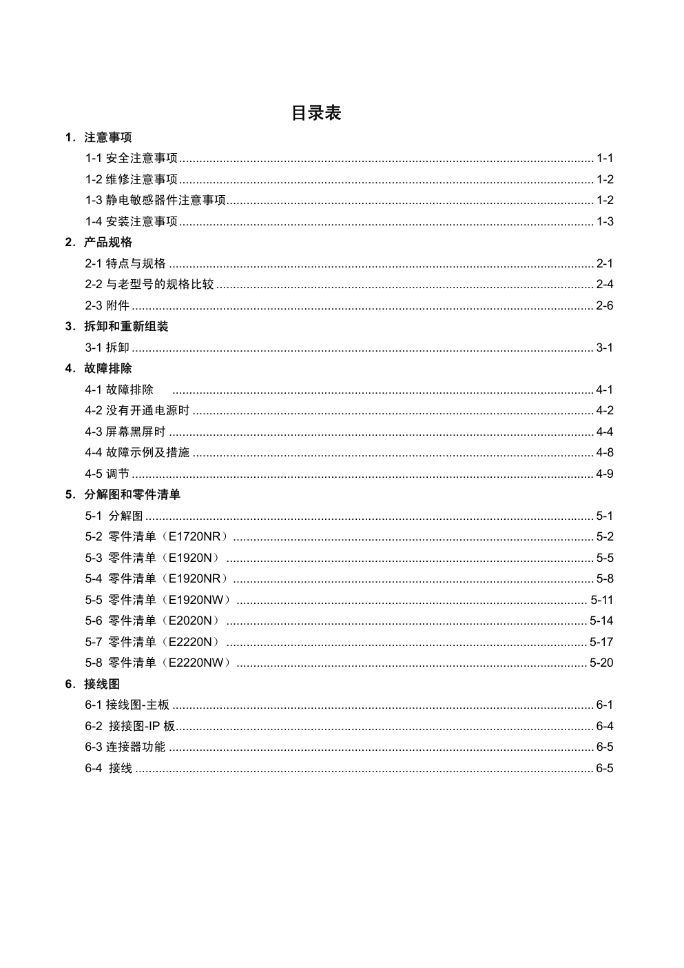
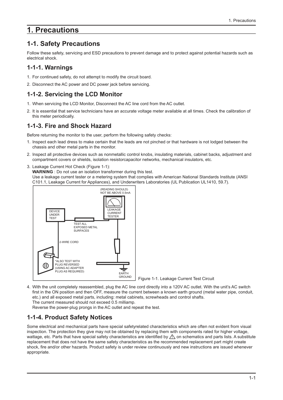
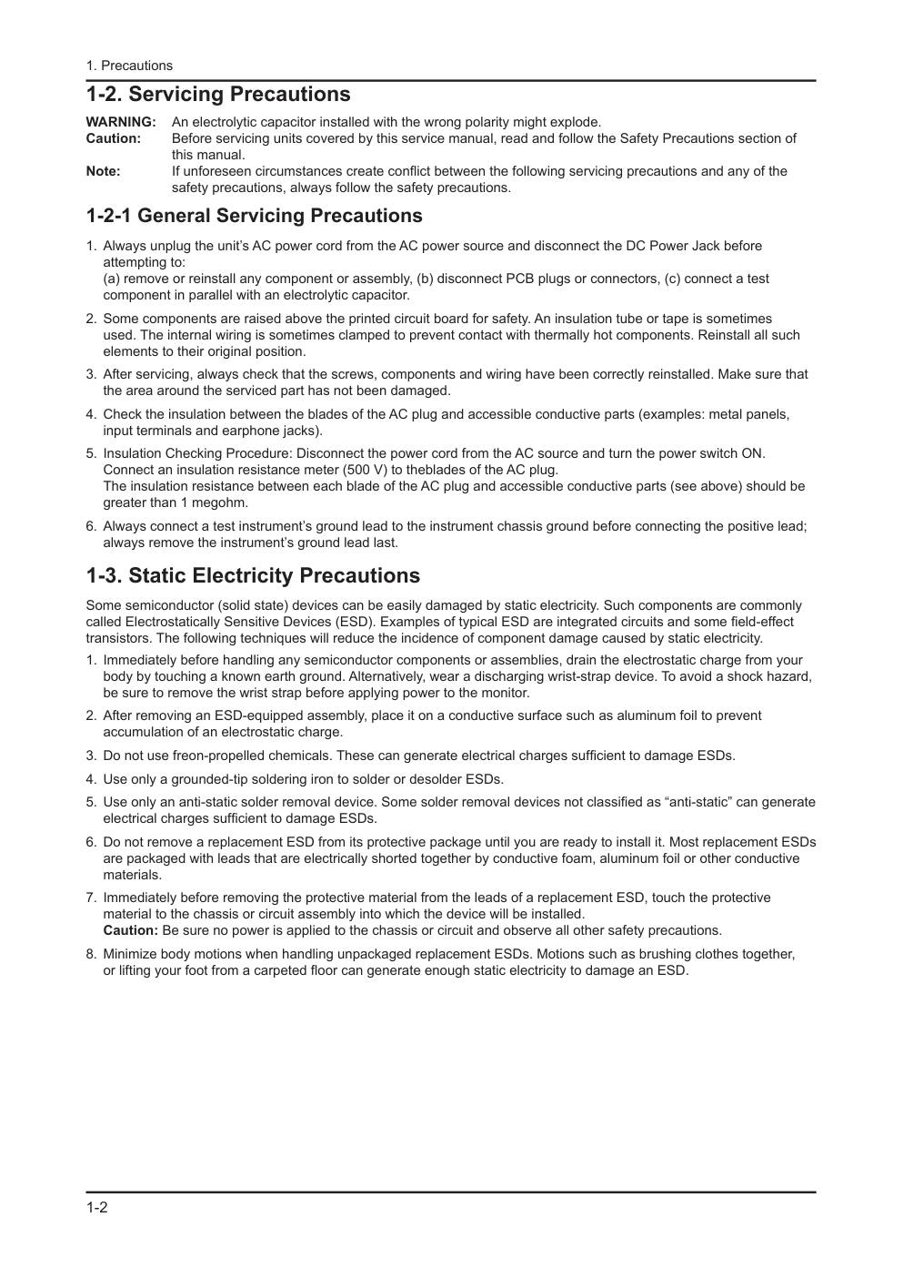
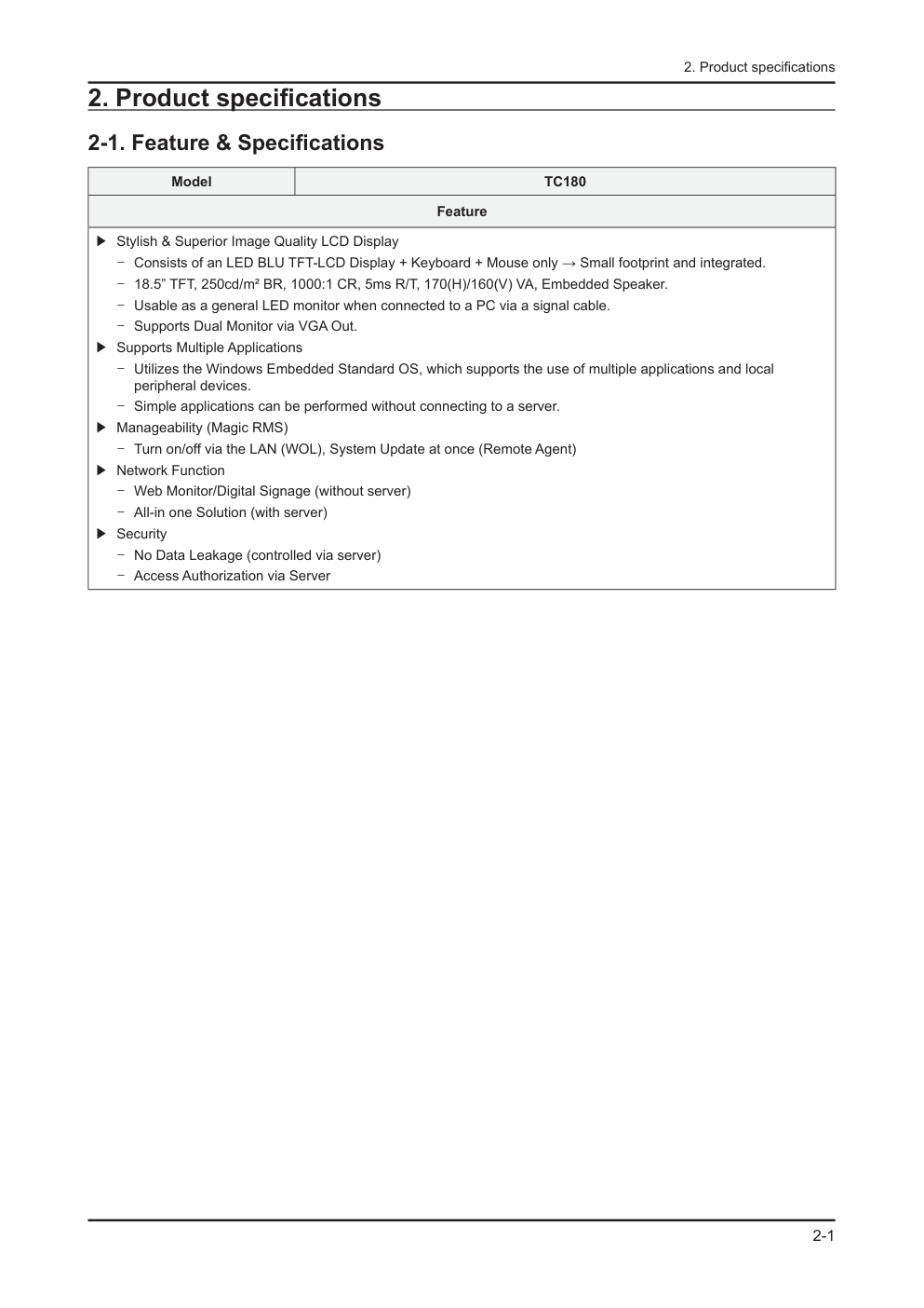
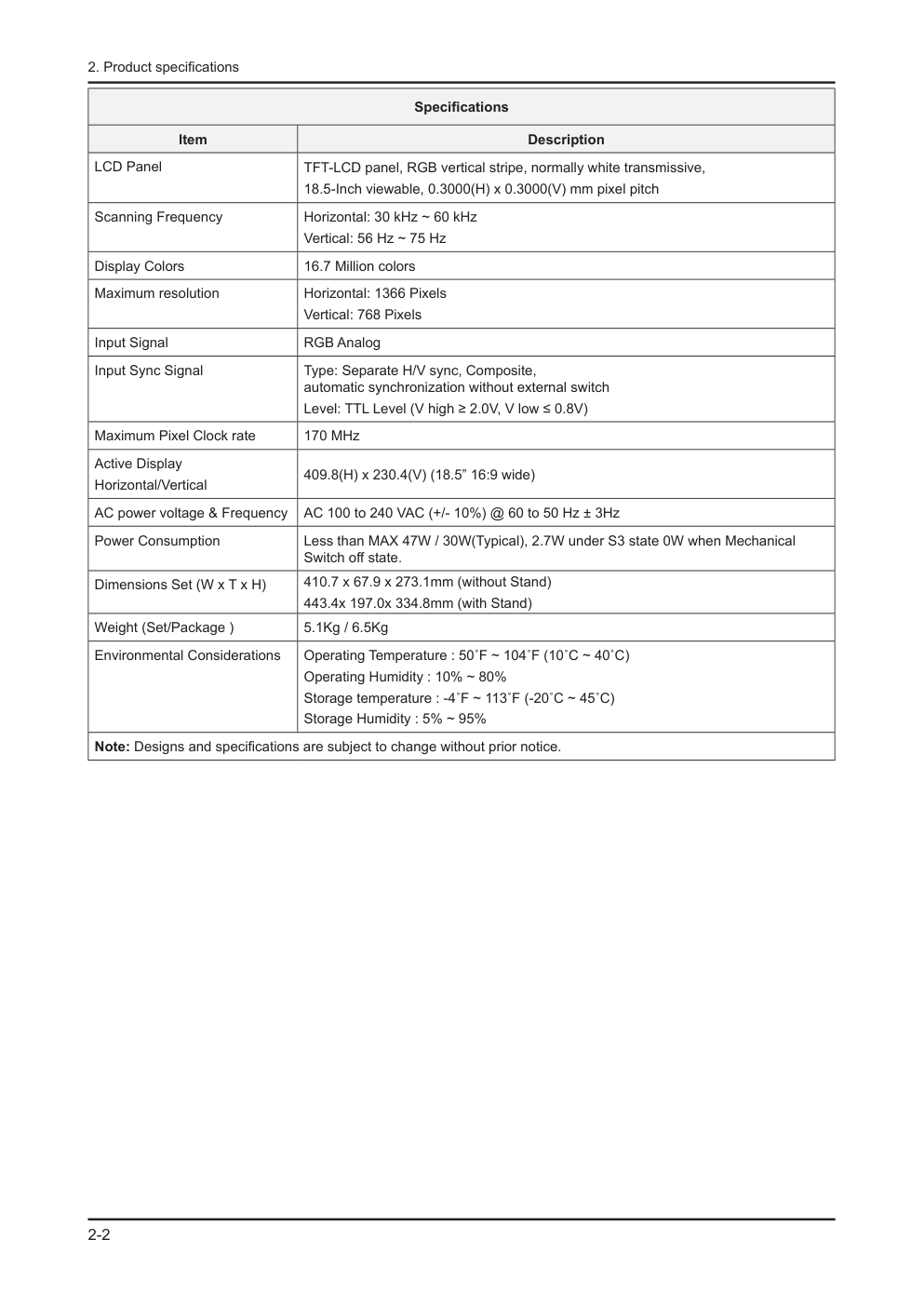
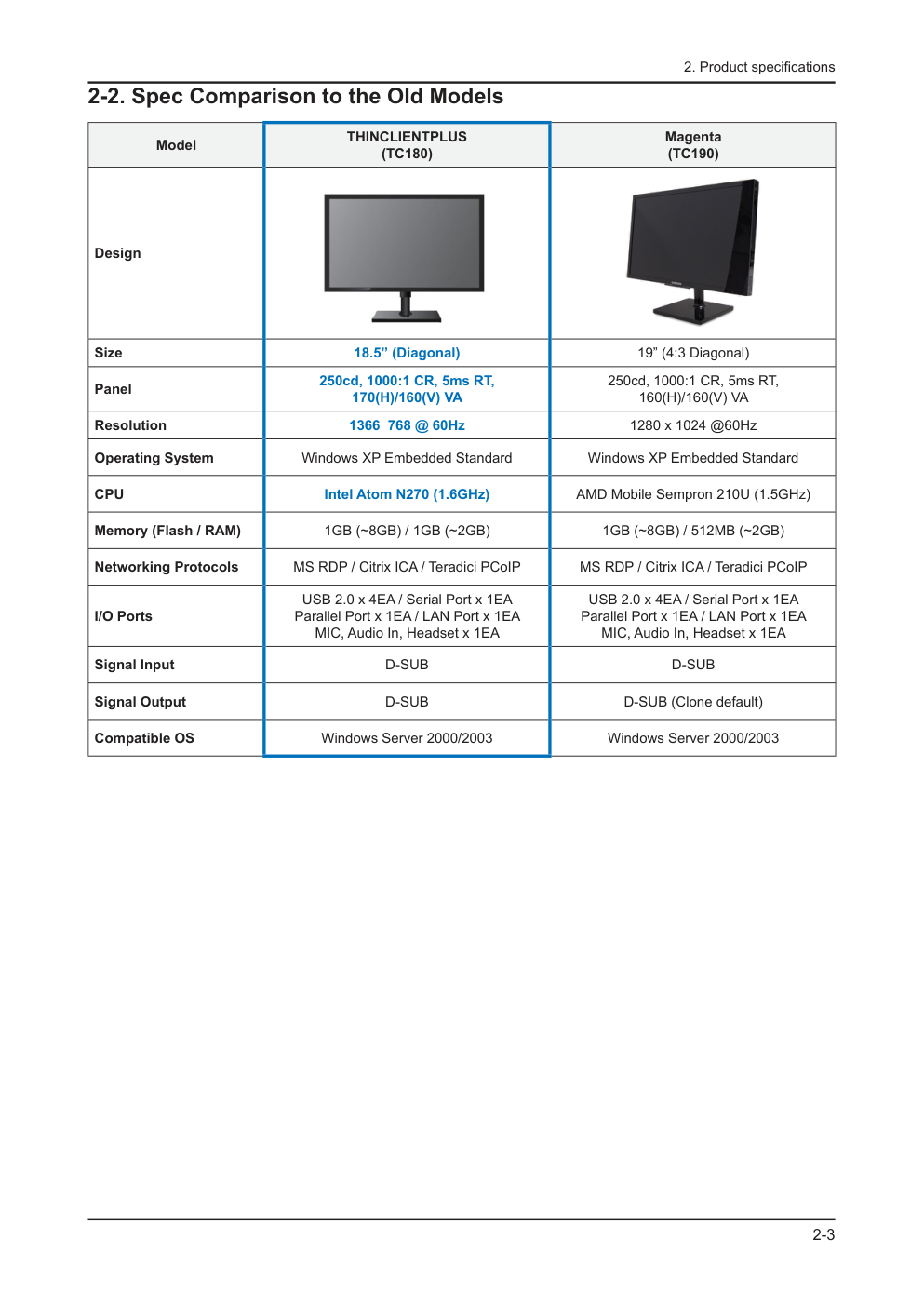
维 修 薄膜液晶显示器 目录 E1720NR/ E1720NRX/ E1920N/ E1920NX/ E1920NR/ E1920NRX/ E1920NW/ E1920NWX/ E2020N/ E2020NX/ E2220N/ E2220NX/ E2220NW / E2420NL 1. 注意事项 2. 产品规格 3. 拆卸和重新组装 4. 故障排除 5. 分解图和零件清单 6. 接线图 参阅 GSPN 维修手册(翻阅封底)获取更多信息。 液晶显示器 底板:LCL17AS / LCL19YS / LCL19AS / LCL19NS / LCL20YS / LCL22YS / LCL22NS / LCL24AS 型号:E1720NR / E1720NRX / E1920N / E1920NX / E1920NR / E1920NRX / E1920NW / E1920NWX / E2020N / E2020NX / E2220N / E2220NX / E2220NW / E2420NL 手 册 目录表 1.注意事项 1-1 安全注意事项........................................................................................................................... 1-1 1-2 维修注意事项........................................................................................................................... 1-2 1-3 静电敏感器件注意事项............................................................................................................. 1-2 1-4 安装注意事项........................................................................................................................... 1-3 2.产品规格 2-1 特点与规格 .............................................................................................................................. 2-1 2-2 与老型号的规格比较 ................................................................................................................ 2-4 2-3 附件 ......................................................................................................................................... 2-6 3.拆卸和重新组装 3-1 拆卸 ......................................................................................................................................... 3-1 4.故障排除 4-1 故障排除 ............................................................................................................................. 4-1 4-2 没有开通电源时 ....................................................................................................................... 4-2 4-3 屏幕黑屏时 .............................................................................................................................. 4-4 4-4 故障示例及措施 ....................................................................................................................... 4-8 4-5 调节 ......................................................................................................................................... 4-9 5.分解图和零件清单 5-1 分解图 ..................................................................................................................................... 5-1 5-2 零件清单(E1720NR)........................................................................................................... 5-2 5-3 零件清单(E1920N) ............................................................................................................. 5-5 5-4 零件清单(E1920NR)........................................................................................................... 5-8 5-5 零件清单(E1920NW)........................................................................................................ 5-11 5-6 零件清单(E2020N) ........................................................................................................... 5-14 5-7 零件清单(E2220N) ........................................................................................................... 5-17 5-8 零件清单(E2220NW)........................................................................................................ 5-20 6.接线图 6-1 接线图-主板 ............................................................................................................................. 6-1 6-2 接接图-IP 板............................................................................................................................ 6-4 6-3 连接器功能 .............................................................................................................................. 6-5 6-4 接线 ........................................................................................................................................ 6-5 GSPN (全球维修合作网络) 国家 网站 北美 service.samsungportal.com 拉丁美洲 latin.samsungportal.com CIS cis.samsungportal.com 欧洲 europe.samsungportal.com 中国 china.samsungportal.com 亚洲 asia.samsungportal.com 中东&非洲 mea.samsungportal.com 本维修手册归三星电子有限公司所有。 未经授权使用该手册可能受到适用的国际和/或国内法 律的惩罚。 © 2010 三星电子有限公司。 版权所有 中国印刷 P/N: BN82-00984A-01 1-1 1. Precautions 1. Precautions 1-1. Safety Precautions Follow these safety, servicing and ESD precautions to prevent damage and to protect against potential hazards such as electrical shock. 1-1-1. Warnings For continued safety, do not attempt to modify the circuit board. 1. Disconnect the AC power and DC power jack before servicing. 2. 1-1-2. Servicing the LCD Monitor When servicing the LCD Monitor, Disconnect the AC line cord from the AC outlet. 1. It is essential that service technicians have an accurate voltage meter available at all times. Check the calibration of 2. this meter periodically. 1-1-3. Fire and Shock Hazard Before returning the monitor to the user, perform the following safety checks: Inspect each lead dress to make certain that the leads are not pinched or that hardware is not lodged between the 1. chassis and other metal parts in the monitor. Inspect all protective devices such as nonmetallic control knobs, insulating materials, cabinet backs, adjustment and 2. compartment covers or shields, isolation resistorcapacitor networks, mechanical insulators, etc. Leakage Current Hot Check (Figure 1-1): 3. WARNING : Do not use an isolation transformer during this test. Use a leakage current tester or a metering system that complies with American National Standards Institute (ANSI C101.1, Leakage Current for Appliances), and Underwriters Laboratories (UL Publication UL1410, 59.7). With the unit completely reassembled, plug the AC line cord directly into a 120V AC outlet. With the unit’s AC switch 4. first in the ON position and then OFF, measure the current between a known earth ground (metal water pipe, conduit, etc.) and all exposed metal parts, including: metal cabinets, screwheads and control shafts. The current measured should not exceed 0.5 milliamp. Reverse the power-plug prongs in the AC outlet and repeat the test. 1-1-4. Product Safety Notices Some electrical and mechanical parts have special safetyrelated characteristics which are often not evident from visual inspection. The protection they give may not be obtained by replacing them with components rated for higher voltage, wattage, etc. Parts that have special safety characteristics are identified by on schematics and parts lists. A substitute replacement that does not have the same safety characteristics as the recommended replacement part might create shock, fire and/or other hazards. Product safety is under review continuously and new instructions are issued whenever appropriate. DEVICE UNDER TEST (READING SHOULD) NOT BE ABOVE 0.5mA LEAKAGE CURRENT TESTER TEST ALL EXPOSED METAL SURFACES 2-WIRE CORD *ALSO TEST WITH PLUG REVERSED (USING AC ADAPTER PLUG AS REQUIRED) EARTH GROUND Figure 1-1. Leakage Current Test Circuit 1-2 1. Precautions 1-2. Servicing Precautions WARNING: An electrolytic capacitor installed with the wrong polarity might explode. Caution: Before servicing units covered by this service manual, read and follow the Safety Precautions section of this manual. Note: If unforeseen circumstances create conflict between the following servicing precautions and any of the safety precautions, always follow the safety precautions. 1-2-1 General Servicing Precautions Always unplug the unit’s AC power cord from the AC power source and disconnect the DC Power Jack before 1. attempting to: (a) remove or reinstall any component or assembly, (b) disconnect PCB plugs or connectors, (c) connect a test component in parallel with an electrolytic capacitor. Some components are raised above the printed circuit board for safety. An insulation tube or tape is sometimes 2. used. The internal wiring is sometimes clamped to prevent contact with thermally hot components. Reinstall all such elements to their original position. After servicing, always check that the screws, components and wiring have been correctly reinstalled. Make sure that 3. the area around the serviced part has not been damaged. Check the insulation between the blades of the AC plug and accessible conductive parts (examples: metal panels, 4. input terminals and earphone jacks). Insulation Checking Procedure: Disconnect the power cord from the AC source and turn the power switch ON. 5. Connect an insulation resistance meter (500 V) to theblades of the AC plug. The insulation resistance between each blade of the AC plug and accessible conductive parts (see above) should be greater than 1 megohm. Always connect a test instrument’s ground lead to the instrument chassis ground before connecting the positive lead; 6. always remove the instrument’s ground lead last. 1-3. Static Electricity Precautions Some semiconductor (solid state) devices can be easily damaged by static electricity. Such components are commonly called Electrostatically Sensitive Devices (ESD). Examples of typical ESD are integrated circuits and some field-effect transistors. The following techniques will reduce the incidence of component damage caused by static electricity. Immediately before handling any semiconductor components or assemblies, drain the electrostatic charge from your 1. body by touching a known earth ground. Alternatively, wear a discharging wrist-strap device. To avoid a shock hazard, be sure to remove the wrist strap before applying power to the monitor. After removing an ESD-equipped assembly, place it on a conductive surface such as aluminum foil to prevent 2. accumulation of an electrostatic charge. Do not use freon-propelled chemicals. These can generate electrical charges sufficient to damage ESDs. 3. Use only a grounded-tip soldering iron to solder or desolder ESDs. 4. Use only an anti-static solder removal device. Some solder removal devices not classified as “anti-static” can generate 5. electrical charges sufficient to damage ESDs. Do not remove a replacement ESD from its protective package until you are ready to install it. Most replacement ESDs 6. are packaged with leads that are electrically shorted together by conductive foam, aluminum foil or other conductive materials. Immediately before removing the protective material from the leads of a replacement ESD, touch the protective 7. material to the chassis or circuit assembly into which the device will be installed. Caution: Be sure no power is applied to the chassis or circuit and observe all other safety precautions. Minimize body motions when handling unpackaged replacement ESDs. Motions such as brushing clothes together, 8. or lifting your foot from a carpeted floor can generate enough static electricity to damage an ESD. 1-3 1. Precautions 1-4. Installation Precautions For safety reasons, more than two people are required for carrying the product. 1. Keep the power cord away from any heat emitting devices, as a melted covering may cause fire or electric shock. 2. Do not place the product in areas with poor ventilation such as a bookshelf or closet. The increased internal 3. temperature may cause fire. Bend the external antenna cable when connecting it to the product. This is a measure to protect it from being exposed 4. to moisture. Otherwise, it may cause a fire or electric shock. Make sure to turn the power off and unplug the power cord from the outlet before repositioning the product. Also check 5. the antenna cable or the external connectors if they are fully unplugged. Damage to the cord may cause fire or electric shock. Keep the antenna far away from any high-voltage cables and install it firmly. Contact with the highvoltage cable or the 6. antenna falling over may cause fire or electric shock. When installing the product, leave enough space (10cm) between the product and the wall for ventilation purposes. 7. A rise in temperature within the product may cause fire. 1-4 1. Precautions Memo 2-1 2. Product specifications 2. Product specifications 2-1. Feature & Specifications Model TC180 Feature Stylish & Superior Image Quality LCD Display ሪ Consists of an LED BLU TFT-LCD Display + Keyboard + Mouse only → Small footprint and integrated. - 18.5” TFT, 250cd/m² BR, 1000:1 CR, 5ms R/T, 170(H)/160(V) VA, Embedded Speaker. - Usable as a general LED monitor when connected to a PC via a signal cable. - Supports Dual Monitor via VGA Out. - Supports Multiple Applications ሪ Utilizes the Windows Embedded Standard OS, which supports the use of multiple applications and local - peripheral devices. Simple applications can be performed without connecting to a server. - Manageability (Magic RMS) ሪ Turn on/off via the LAN (WOL), System Update at once (Remote Agent) - Network Function ሪ Web Monitor/Digital Signage (without server) - All-in one Solution (with server) - Security ሪ No Data Leakage (controlled via server) - Access Authorization via Server - 2-2 2. Product specifications Specifications Item Description LCD Panel TFT-LCD panel, RGB vertical stripe, normally white transmissive, 18.5-Inch viewable, 0.3000(H) x 0.3000(V) mm pixel pitch Scanning Frequency Horizontal: 30 kHz ~ 60 kHz Vertical: 56 Hz ~ 75 Hz Display Colors 16.7 Million colors Maximum resolution Horizontal: 1366 Pixels Vertical: 768 Pixels Input Signal RGB Analog Input Sync Signal Type: Separate H/V sync, Composite, automatic synchronization without external switch Level: TTL Level (V high ≥ 2.0V, V low ≤ 0.8V) Maximum Pixel Clock rate 170 MHz Active Display Horizontal/Vertical 409.8(H) x 230.4(V) (18.5” 16:9 wide) AC power voltage & Frequency AC 100 to 240 VAC (+/- 10%) @ 60 to 50 Hz ± 3Hz Power Consumption Less than MAX 47W / 30W(Typical), 2.7W under S3 state 0W when Mechanical Switch off state. Dimensions Set (W x T x H) 410.7 x 67.9 x 273.1mm (without Stand) 443.4x 197.0x 334.8mm (with Stand) Weight (Set/Package ) 5.1Kg / 6.5Kg Environmental Considerations Operating Temperature : 50˚F ~ 104˚F (10˚C ~ 40˚C) Operating Humidity : 10% ~ 80% Storage temperature : -4˚F ~ 113˚F (-20˚C ~ 45˚C) Storage Humidity : 5% ~ 95% Note: Designs and specifications are subject to change without prior notice. 2-3 2. Product specifications 2-2. Spec Comparison to the Old Models Model THINCLIENTPLUS (TC180) Magenta (TC190) Design Size 18.5” (Diagonal) 19” (4:3 Diagonal) Panel 250cd, 1000:1 CR, 5ms RT, 170(H)/160(V) VA 250cd, 1000:1 CR, 5ms RT, 160(H)/160(V) VA Resolution 1366 768 @ 60Hz 1280 x 1024 @60Hz Operating System Windows XP Embedded Standard Windows XP Embedded Standard CPU Intel Atom N270 (1.6GHz) AMD Mobile Sempron 210U (1.5GHz) Memory (Flash / RAM) 1GB (~8GB) / 1GB (~2GB) 1GB (~8GB) / 512MB (~2GB) Networking Protocols MS RDP / Citrix ICA / Teradici PCoIP MS RDP / Citrix ICA / Teradici PCoIP I/O Ports USB 2.0 x 4EA / Serial Port x 1EA Parallel Port x 1EA / LAN Port x 1EA MIC, Audio In, Headset x 1EA USB 2.0 x 4EA / Serial Port x 1EA Parallel Port x 1EA / LAN Port x 1EA MIC, Audio In, Headset x 1EA Signal Input D-SUB D-SUB Signal Output D-SUB D-SUB (Clone default) Compatible OS Windows Server 2000/2003 Windows Server 2000/2003 2-4 2. Product specifications 2-3. Accessories Product Description Ccde. No Remark Quick Setup Guide BN68-03222A Samsung Electronics Service center Warranty Card (Not available in all locations) BN68-01925H User’s Guide, Monitor Driver BN59-01125A Power Cord 3903-000452 2-4. Accessories (Sold separately) Product Description Ccde. No Remark D-SUB Cable BN39-00244B Samsung Electronics Service center Keyboard (USB) Mouse (USB) 3 拆卸和重新组装 3-1 3.拆卸和组装 维修手册的这一章叙述本显示器的拆卸和重新组装步骤。 警告:本显示器包含静电敏感器件。处理这些部件时应小心。 3-1. 拆卸 小心:1.在进行拆卸前,请关闭显示器。 2.在拆卸显示器时,请勿使用除提供的开启工具以外的其它金属工具。 3.请按下述步骤小心拆卸本显示器。 说明 图片说明 螺钉 1.拆卸基座。 2.1翻转显示器并将手插入到显示器顶部中 央位置,按照如图箭头所示方向拆卸前盖。 2如图所示,分离前盖侧部到指示线位置。 3 拆卸和重新组装 3-2 说明 图片说明 螺钉 3.再次翻转显示器。 3 拆卸和重新组装 3-3 说明 图片说明 螺钉 4.再次翻转显示器并拆卸后盖。 5.拆卸 LVDS、灯接线和功能线后拆卸护 板盖。 6.拆卸液晶显示屏板。 7.拆卸如图所示处的两(2)处螺钉。 3 拆卸和重新组装 3-4 说明 图片说明 螺钉 8.拆卸如图所示处的四(4)个螺钉及支 撑架。 9.从护板盖位置处卸下主印刷电路板和 IP 板。 IP 板 主板 ※ 重新组装步骤与拆卸步骤相反。 4 故障排除 4-1 4 故障排除 4-1. 故障排除 1. 在进行故障排除之前,按如下方式设置制式模式: E1720NR/E1920NR E1920N E1920NW 分辨率:1280×1024 水平频率:60kHz 竖直频率:64Hz 分辨率:1360×768 水平频率:60kHz 竖直频率:47.7Hz 分辨率:1440×900 水平频率:60kHz 竖直频率:55.9Hz E2020N E2220N E2220NW E2420NL 分辨率:1600×900 水平频率:60kHz 竖直频率:60Hz 分辨率:1920×1080 水平频率:60kHz 竖直频率:67.5Hz 分辨率:1680×1050 水平频率:60kHz 竖直频率:64.7Hz 分辨率:1920×1080 水平频率:60kHz 竖直频率:67.5Hz 2. 如果没有图像出现,确保正确连接了电源线。 3. 检查以下电路: � 没有光栅出现:功能印刷电路板组件、主印刷电路板组件、I/P 印刷电路板组件 � 5V 形成,但没有画面:主印刷电路板组件 � 5V 没有形成:I/P 印刷电路板组件 4. 按下菜单键并按住“ (确认/来源)”键五(5)秒,显示器会自动进入工厂预设。 4 故障排除 4-2 4-2 电源未开通时 征兆 -连接电源后打开电源按钮时,显示器前部的 LED 指示灯不运行。 主要检查点 -连接电源线后打开电源按钮,显示器前部的 LED 灯不运行。 -检查 IP 板保险丝和 IP 板输出功率。 -检查 IP 板和显示器内部主板的连接情况。 -检查主板电源部分,同时检查其它输出终端是否有任何输出异常。 诊断 注意 在 IP 板工作之前确保电源断开。 否 否 是 是 IC601 管脚 4 电压为 DC5V 时管脚 5 所测电压是否为 DC3.3V? IC602 管脚 4 电压为 DC5V 时管脚 5 所测电压是否为 DC1.8V? 检查并更换 IP 板 检查 IC601 上的相关电路 检查 IC602 上的相关电路 否 是 CN600 连接器在管脚 3、4、5 电压 为 0V 时管脚 6、7 所测电压是否为 DC5V? 更换 IP 板 检查功能组件的连接状况 是 4-3 1 2 3 4-2-1 电源未开通时的电路图 4 故障排除 4 故障排除 4-4 4-3. 当显示器黑屏时 征兆 -尽管 LED 电源打开,但连接 VGA 接线时,屏幕仍为黑屏。 主要检查点 -即使 LED 电源打开,连接 VGA 接线时,屏幕仍为黑屏 -检查 D-SUB 接线的连接情况。 -检查 LVDS 接线是否正确连接到面板上。 -检查面板灯连接器是否正确连接到了 IP 板上。 诊断 注意 在 IP 板工作之前确保电源断开。 否 否 否 否 是 是 是 ○2 在 R204、R207、和 R211 上是 否出现了 RGB 输入? 检查 IC400 的管脚 14、15 上是否出现了○3 水平同步和○4 竖直同步的波形? CN400 的管脚 8 到管脚 30 是否出现 了输出信号? 在 CN400 的管脚 1、2、3 上的电压 是否为 DC5V? 检查 R204、R207、和 R211 的 输入终端 检查 IC400 和相关电路 检查 CN400 和相关电路 检查 +5V_板信号和 BL_EN 信号 否 是 ○1 检查 X400 震荡是否正常? 如果需要检查并更换与 X400 相 关的电路。 是 检查并更换屏板 是 检查信号接线及其连接 4 故障排除 4-5 4-3-1. 当显示黑屏时 2 3 1 4 4-6 E1720NR / E1720NRX / E1920NR / E1920NRX / E1920NW / E1920NWX / E2020N / E2020NX / E2220N / E2220NX / E2220NW / E2420NL E1920N / E1920NX 4 故障排除 4 故障排除 4-7 4-3-2. 显示器上无显示时的波形图 1 3 4 4 故障排除 4-8 4-4 故障示例及校正措施 故障图片 征兆和校正措施 备注 征兆:打开显示器时,无论是否有信号,连 续显示全白图案。 原因:由于 LVDS 接线发生故障或错误连接, 在仅供应灯电源并且未向面板输入视频信号 时会发生此故障。 校正措施:更换或重新正确连接 LVDS 接线, 以能够将视频信号输入到面板中。 *全白图案是TN面板的一个特点, 可在未输入视频信号时显示。 4 故障排除 4-9 4-5. 调节 4-5-1.维修调节条件 1.维修调节前的注意事项 1)检查维修调节的设备是否操作正常。 2)为了安全在足够大的空间处拆卸显示器。 3)在拆卸前准备一块软垫。 2.进入维修模式 进入: 菜单 亮度 0 对比度 0 按下确认键 5 秒 退出: 关闭电源 开启电源 3.更换板后的基本维修项目 1)检查 PC 颜色调节状态。 2)DDC 输入(模拟和数字输入) 3)检查此型号是否有合适的 MCU 代码输入。 4)进入维修模式后硬关机并进行预设。 4. DDC EDIT 数据输入 1)在 AD 板代码更新时使用。 2)通过三星电子质量控制部门下载适于该机型的 WinDDC 程序、DDC 输入程序和 DDC 文件。 安装以下装置并输入数据,如图所示。 显示器需要调节 MTI-2055 DDC 管理器 并行连接器 (25 针电缆) 连接显示器 (信号电缆) 4 故障排除 4-10 4-5-2.维修功能规格 检查代码版本 1.进入 SVC 模式后检查 MCU 代码版本和检验和。 2.进入 SVC 模式 -设置亮度和对比度到 0。 -按下确定键和来源键五(5)秒。 -出现在屏显示调节 SVC 功能。 -如要退出在屏显示调节功能,你必须先要关闭电源 3.安全模式 -当输入信号高于产品所限的频率后,安全模式会给用户提供些时间(1 分钟)来改变视频卡的设置到被应 许的模式设置下。 板面信息 选择自动选项 选择像素切换选项 国家 定标器销售 Micom 版本 Micom 检验和 � 维修模式(移动) 1.按下-按钮,选择菜单。 4 故障排除 4-11 2.按下-号按钮,更改设置到开或关。 ■更换面板时 更换面板后,选择面板项目并按下菜单按钮五(5)秒。 板面 Ch.No 将会增加 1,且时间信息会更改到 0。 这个数字增加 1 4 故障排除 4-12 � 输入 DDC 数据 使用 DDC 管理器 MTI-2050 版本或更新 1.点击打开[F5]图标。 2.选择一个端口。 3.打开 DDC 文件。 4.选择一个日期并点击确认[保存]按钮。 5.点击下一步[确定]按钮。 6.输入系列编号并按下确认键。 ※输入模拟数据后,再输入数字数据,重复此过程 2 到 5 次。 4 故障排除 4-13 � 输入 MCU 数据 1) 打开“Easywriter”后检查如下选项。 -选项:设置 ISP 工具 - LPT端口偏移:378 - ISP Jig类型选择:三星 - 自动检测 - 确认变更 4 故障排除 4-14 2)点击载入文件按钮。 3)选择 MCU 代码文件,并点击打开[O]按钮。 4 故障排除 4-15 4)点击自动按钮。 5)当进程和检验完成时,将显示器硬关机并再次开启。 4 故障排除 4-16 备忘录 6-1 E1720NR / E1720NRX / E1920NR / E1920NRX / E1920NW / E1920NWX / E2020N / E2020NX / E2220N / E2220NX / E2220NW 6.接线图 6. 接线图 6-1.接线图-主板 6-2 E1920N / E1920NX 6.接线图 6.接线图 6-3 编号 模块 功能说明 备注 1 定标器 IC200 ADC、TMDS、缩放比例和控制器被整合至单一芯 片上。 SE919LM-NT 2 闪存 IC401 为定标器存储固件,信息可以被升级。 3 EEPROM IC402 存储OSD,定时等等。 NVRAM 24C08 4 EEPROM IC202 存储EDID数据。 24C02 5 校准仪 IC601、IC602 集成电路用于稳定直流电源。 S-1172B33-U5T1G S-1172B18-U5T1G 6.接线图 6-4 6-2.接线图-IP板 LVDS连接器 (连接至屏板) IP板 功能连接器 (连接至IP板) RGB连接器 (连接至计算机) 6.接线图 6-5 6-3.连接器功能 连接器 功能 CN802↔CN600 从电源板至主板提供 5V 电压并从电源板至转换器传输 PWM 输出电压。 *当发生故障时:可能发生无电量和黑屏故障。 CN1 ~ CN4 In 由转换器至屏板灯所产生的传输电流为(6mA ~ 7mA) *当发生故障时:可能发生黑屏。 CN200 VGA 信号输入终端 *当发生故障时:可能发生 RGB 输出故障。 CN400 从主板至屏板传输 LVDS 信号。 *当发生故障时:可能发生黑屏及无电量故障。 6-4.接线 使用 LVDS 30P FFC 接线 代码 BN96-02854X(E1720NR/ E1720NRX) 照片 代码 BN96-02854W (E1920N/ E1920NX/E1920NW/ E1920NWX/E2020N/ E2020NX) 照片 代码 BN96-02854Y(E1920NR/ E1920NRX/E2220N/ E2220NX) 照片 代码 BN96-12447G(E2220NW) 照片 6.接线图 6-6 备忘录
版权声明
1. 本站所有素材,仅限学习交流,仅展示部分内容,如需查看完整内容,请下载原文件。
2. 会员在本站下载的所有素材,只拥有使用权,著作权归原作者所有。
3. 所有素材,未经合法授权,请勿用于商业用途,会员不得以任何形式发布、传播、复制、转售该素材,否则一律封号处理。
4. 如果素材损害你的权益请联系客服QQ:77594475 处理。